EP1749329B1 - Safety element for battery and battery with the same - Google Patents
Safety element for battery and battery with the same Download PDFInfo
- Publication number
- EP1749329B1 EP1749329B1 EP05740769.4A EP05740769A EP1749329B1 EP 1749329 B1 EP1749329 B1 EP 1749329B1 EP 05740769 A EP05740769 A EP 05740769A EP 1749329 B1 EP1749329 B1 EP 1749329B1
- Authority
- EP
- European Patent Office
- Prior art keywords
- battery
- mit
- safety element
- temperature
- resistance
- Prior art date
- Legal status (The legal status is an assumption and is not a legal conclusion. Google has not performed a legal analysis and makes no representation as to the accuracy of the status listed.)
- Expired - Lifetime
Links
Images


Classifications
-
- H—ELECTRICITY
- H01—ELECTRIC ELEMENTS
- H01M—PROCESSES OR MEANS, e.g. BATTERIES, FOR THE DIRECT CONVERSION OF CHEMICAL ENERGY INTO ELECTRICAL ENERGY
- H01M50/00—Constructional details or processes of manufacture of the non-active parts of electrochemical cells other than fuel cells, e.g. hybrid cells
- H01M50/20—Mountings; Secondary casings or frames; Racks, modules or packs; Suspension devices; Shock absorbers; Transport or carrying devices; Holders
-
- H—ELECTRICITY
- H01—ELECTRIC ELEMENTS
- H01C—RESISTORS
- H01C7/00—Non-adjustable resistors formed as one or more layers or coatings; Non-adjustable resistors made from powdered conducting material or powdered semi-conducting material with or without insulating material
- H01C7/04—Non-adjustable resistors formed as one or more layers or coatings; Non-adjustable resistors made from powdered conducting material or powdered semi-conducting material with or without insulating material having negative temperature coefficient
- H01C7/042—Non-adjustable resistors formed as one or more layers or coatings; Non-adjustable resistors made from powdered conducting material or powdered semi-conducting material with or without insulating material having negative temperature coefficient mainly consisting of inorganic non-metallic substances
- H01C7/043—Oxides or oxidic compounds
- H01C7/045—Perovskites, e.g. titanates
-
- H—ELECTRICITY
- H01—ELECTRIC ELEMENTS
- H01C—RESISTORS
- H01C7/00—Non-adjustable resistors formed as one or more layers or coatings; Non-adjustable resistors made from powdered conducting material or powdered semi-conducting material with or without insulating material
- H01C7/04—Non-adjustable resistors formed as one or more layers or coatings; Non-adjustable resistors made from powdered conducting material or powdered semi-conducting material with or without insulating material having negative temperature coefficient
- H01C7/042—Non-adjustable resistors formed as one or more layers or coatings; Non-adjustable resistors made from powdered conducting material or powdered semi-conducting material with or without insulating material having negative temperature coefficient mainly consisting of inorganic non-metallic substances
- H01C7/043—Oxides or oxidic compounds
- H01C7/047—Vanadium oxides or oxidic compounds, e.g. VOx
-
- H—ELECTRICITY
- H01—ELECTRIC ELEMENTS
- H01M—PROCESSES OR MEANS, e.g. BATTERIES, FOR THE DIRECT CONVERSION OF CHEMICAL ENERGY INTO ELECTRICAL ENERGY
- H01M10/00—Secondary cells; Manufacture thereof
- H01M10/05—Accumulators with non-aqueous electrolyte
- H01M10/052—Li-accumulators
- H01M10/0525—Rocking-chair batteries, i.e. batteries with lithium insertion or intercalation in both electrodes; Lithium-ion batteries
-
- H—ELECTRICITY
- H01—ELECTRIC ELEMENTS
- H01M—PROCESSES OR MEANS, e.g. BATTERIES, FOR THE DIRECT CONVERSION OF CHEMICAL ENERGY INTO ELECTRICAL ENERGY
- H01M10/00—Secondary cells; Manufacture thereof
- H01M10/42—Methods or arrangements for servicing or maintenance of secondary cells or secondary half-cells
- H01M10/425—Structural combination with electronic components, e.g. electronic circuits integrated to the outside of the casing
-
- H—ELECTRICITY
- H01—ELECTRIC ELEMENTS
- H01M—PROCESSES OR MEANS, e.g. BATTERIES, FOR THE DIRECT CONVERSION OF CHEMICAL ENERGY INTO ELECTRICAL ENERGY
- H01M10/00—Secondary cells; Manufacture thereof
- H01M10/42—Methods or arrangements for servicing or maintenance of secondary cells or secondary half-cells
- H01M10/425—Structural combination with electronic components, e.g. electronic circuits integrated to the outside of the casing
- H01M10/4257—Smart batteries, e.g. electronic circuits inside the housing of the cells or batteries
-
- H—ELECTRICITY
- H01—ELECTRIC ELEMENTS
- H01M—PROCESSES OR MEANS, e.g. BATTERIES, FOR THE DIRECT CONVERSION OF CHEMICAL ENERGY INTO ELECTRICAL ENERGY
- H01M10/00—Secondary cells; Manufacture thereof
- H01M10/42—Methods or arrangements for servicing or maintenance of secondary cells or secondary half-cells
- H01M10/44—Methods for charging or discharging
- H01M10/443—Methods for charging or discharging in response to temperature
-
- H—ELECTRICITY
- H01—ELECTRIC ELEMENTS
- H01M—PROCESSES OR MEANS, e.g. BATTERIES, FOR THE DIRECT CONVERSION OF CHEMICAL ENERGY INTO ELECTRICAL ENERGY
- H01M10/00—Secondary cells; Manufacture thereof
- H01M10/60—Heating or cooling; Temperature control
- H01M10/63—Control systems
- H01M10/637—Control systems characterised by the use of reversible temperature-sensitive devices, e.g. NTC, PTC or bimetal devices; characterised by control of the internal current flowing through the cells, e.g. by switching
-
- H—ELECTRICITY
- H01—ELECTRIC ELEMENTS
- H01M—PROCESSES OR MEANS, e.g. BATTERIES, FOR THE DIRECT CONVERSION OF CHEMICAL ENERGY INTO ELECTRICAL ENERGY
- H01M50/00—Constructional details or processes of manufacture of the non-active parts of electrochemical cells other than fuel cells, e.g. hybrid cells
- H01M50/50—Current conducting connections for cells or batteries
- H01M50/572—Means for preventing undesired use or discharge
-
- H—ELECTRICITY
- H02—GENERATION; CONVERSION OR DISTRIBUTION OF ELECTRIC POWER
- H02H—EMERGENCY PROTECTIVE CIRCUIT ARRANGEMENTS
- H02H7/00—Emergency protective circuit arrangements specially adapted for specific types of electric machines or apparatus or for sectionalised protection of cable or line systems, and effecting automatic switching in the event of an undesired change from normal working conditions
- H02H7/18—Emergency protective circuit arrangements specially adapted for specific types of electric machines or apparatus or for sectionalised protection of cable or line systems, and effecting automatic switching in the event of an undesired change from normal working conditions for batteries; for accumulators
-
- H—ELECTRICITY
- H02—GENERATION; CONVERSION OR DISTRIBUTION OF ELECTRIC POWER
- H02H—EMERGENCY PROTECTIVE CIRCUIT ARRANGEMENTS
- H02H9/00—Emergency protective circuit arrangements for limiting excess current or voltage without disconnection
- H02H9/04—Emergency protective circuit arrangements for limiting excess current or voltage without disconnection responsive to excess voltage
- H02H9/041—Emergency protective circuit arrangements for limiting excess current or voltage without disconnection responsive to excess voltage using a short-circuiting device
-
- H—ELECTRICITY
- H01—ELECTRIC ELEMENTS
- H01M—PROCESSES OR MEANS, e.g. BATTERIES, FOR THE DIRECT CONVERSION OF CHEMICAL ENERGY INTO ELECTRICAL ENERGY
- H01M2200/00—Safety devices for primary or secondary batteries
- H01M2200/10—Temperature sensitive devices
-
- Y—GENERAL TAGGING OF NEW TECHNOLOGICAL DEVELOPMENTS; GENERAL TAGGING OF CROSS-SECTIONAL TECHNOLOGIES SPANNING OVER SEVERAL SECTIONS OF THE IPC; TECHNICAL SUBJECTS COVERED BY FORMER USPC CROSS-REFERENCE ART COLLECTIONS [XRACs] AND DIGESTS
- Y02—TECHNOLOGIES OR APPLICATIONS FOR MITIGATION OR ADAPTATION AGAINST CLIMATE CHANGE
- Y02E—REDUCTION OF GREENHOUSE GAS [GHG] EMISSIONS, RELATED TO ENERGY GENERATION, TRANSMISSION OR DISTRIBUTION
- Y02E60/00—Enabling technologies; Technologies with a potential or indirect contribution to GHG emissions mitigation
- Y02E60/10—Energy storage using batteries
Definitions
- the present invention relates to a safety element for a battery, which is provided with material having a Metal-Insulator Transition (MIT) characteristic where resistance abruptly drops at or above a certain temperature, and to a battery with such a safety element.
- MIT Metal-Insulator Transition
- positive electrode active material is sensitive to a voltage
- reactivity between the positive electrode and the electrolyte is enhanced as the battery is charged and so the voltage becomes higher, which not only causes dissolution of a positive electrode surface and oxidation of the electrolyte, but also increases the risk of firing or explosion.
- a safety element is externally or internally connected to the battery, the safety element being provided with material having large change in resistance such that an electric current abruptly flows through it at or above a certain temperature while no large current leakage occurs at a normal use temperature of the battery.
- a safety element which is provided with material having a Metal-Insulator Transition (MIT) characteristic where resistance abruptly drops at or above a certain temperature, and a battery positive and negative electrodes of which are connected to each other through such a safety element.
- MIT Metal-Insulator Transition
- a battery is characterized by comprising a safety element connected between its positive and negative electrodes, the safety element comprising material having a Metal-Insulator Transition (MIT) characteristic where resistance abruptly drops at or above a certain temperature, as a way to sense the rise of a battery temperature and lower a charged state of the battery when the battery is exposed to an elevated temperature or the battery temperature rises due to external impact by pressure, nails or nippers, the rise of an ambient temperature or overcharging.
- MIT Metal-Insulator Transition
- the MIT characteristic is a material-specific characteristic which is presented by only materials including vanadium-based oxides such as VO, VO or V 2 O 3 and Ti 2 O 3 material or such materials to which an element such as Ba, La, etc. is added, where resistance of the materials abruptly changes according to a temperature (See FIG. 2 ).
- the change in resistance is caused by phase transition of a crystalline structure between a metal and an insulator.
- 'MIT safety element' material having an MIT characteristic
- NTC Negative Temperature Coefficient
- material having an NTC characteristic is a semiconductor element having a negative temperature coefficient characteristic where resistance decrease with the rise of a temperature.
- a semiconductor is characterized in that its resistivity decreases with the increase of a temperature.
- 'MTT material' material having the MIT characteristic where phase transition occurs between a metal and an insulator is quite different from the NTC material.
- the NTC material must have a resistance value of at least 10k ⁇ to 5k ⁇ so that it can operate without a problem such as current leakage at a normal temperature. In this case, the NTC material cannot flow enough electric current to safely protect a battery when a temperature rises. Accordingly, NTC material having low resistance at a normal temperature must be used in order to have a sufficient flow of electric current.
- NTC material having low resistance for example having a resistance value of 1k ⁇
- the battery in an overdischarged state exhibits a phenomenon in which performance of the battery abruptly deteriorates due to dissolution of Cu, etc., on a negative electrode.
- a safety element consisting of NTC material having a low initial resistance value may collapse when an excess electric current flows at an elevated temperature, so that the safety element loses its capability as an NTC element and resistance increases.
- Such an element is transformed into an element not coinciding with the purpose of the present invention. Furthermore, since resistance of the NTC material does not decrease at a specific temperature, but decrease with the rise of a temperature, the NTC material has another disadvantage in that a leakage current becomes larger at a battery's usable temperature of 50 °C to 60 °C even in a case of NTC material having a very low leakage current at a normal temperature. As an example, 10k ⁇ -NTC material having constant B of 4000 shows about a leakage current of 2mAat a temperature of 60 °C.
- MIT material experiences resistance change only in a specific temperature range and exhibits insulating characteristic having no influence on the battery at a battery's usable temperature of -20 °C to 60 °C.
- This phenomenon is attributed to structural change of crystalline and mostly occurs in vanadium-based materials such as VO, VO 2 or V 2 O 3 .
- vanadium-based materials such as VO, VO 2 or V 2 O 3 .
- a sufficient electric current can flow through them only when a temperature rises to or above a critical point and thus enable a battery to rapidly become a discharged state, while no large current leakage occurs at a battery's usable temperature.
- a critical temperature of the MIT material for resistance change preferably lies in a range of 50 °C to 150 °C.
- a battery is discharged at its normal use temperature between 20 °C and 60 °C to reduce residual capacity of the battery.
- this decrease of resistance has no influence on battery safety because the battery has been already swelled, fired or exploded due to external impact or environmental changes.
- an MIT safety element is constructed by connecting a metal lead wire having high electrical conductivity to any two places of MIT material having a certain form, respectively without bringing into contact with each other and the so-constructed MIT safety element is connected to positive and negative electrode terminals of a battery through the two lead wires.
- the MIT material portion of the MIT safety element may be sealed with packing material such as epoxy or glass.
- an MIT safety element is constructed in the form of a chip and the so-constructed MIT safety element may be connected directly to positive and negative electrode terminals of a battery.
- an MIT safety element is constructed in the form of a chip both ends of which is coated with metal films and the so-constructed MIT safety element may be connected directly to positive and negative electrode terminals of a battery.
- the safety element of the present invention may be provided inside or outside of a cell, or in a protective circuit (See FIG. 1 ).
- both positive and negative electrode terminals of a battery are connected to each other using MIT material inside or outside of the battery, an electric current does not flow through the MIT material between the positive and negative electrodes at a normal use temperature of the battery because the MIT material has very large resistance at that temperature. That is, the MIT material has no influence on the battery.
- resistance of the MIT material abruptly drops and an electric current flows through the MIT material between the positive and negative electrodes, which causes the battery to be discharged and thus turns it into a safe state.
- the MIT safety element when used in a battery, explosion or firing does not occur even if the battery is exposed to an elevated temperature. If a temperature is lowered again, resistance of the MIT material becomes larger again and an electric current does not flow any more, so that the battery can be used normally.
- FIG. 1 illustrates two concrete states in which the MIT safety element is connected to a secondary battery in different manners in accordance with preferred embodiments of the present invention.
- the MIT safety element of the present invention is connected to a polymer battery.
- a polymer battery has a laminate-type structure and includes one or more positive electrode plates and one or more negative electrode plates alternately laminated with the positive electrode plates.
- a positive electrode lead connecting the one or more positive electrode plates to each other and to the exterior of a cell, and a negative electrode lead connecting the one or more negative electrode plates to each other and to the exterior of the cell are connected to a power source located outside of a cell packing material.
- the MIT safety element of the present invention in which the MIT material is connected in parallel to a middle portion of a metal connector is connected between the positive and negative electrode leads inside or outside of the cell packing material.
- a lithium secondary battery In a case of a lithium secondary battery, it fires or explodes when heated to or above 160 °C in a charged state.
- the MIT material resistance of which changes in a temperature range of 50 °C to 150 °C, is connected in parallel to positive and negative electrode terminals of the lithium secondary battery, an electric current flows toward the MIT material through which the electric current has not flowed hitherto to change the charged lithium secondary battery into a discharged state because resistance of the MIT material abruptly drops in the above-mentioned temperature range. That is, the lithium secondary battery will not fire or explode even if it is heated to or above 160 °C .
- a cell was constructed such that its positive electrode consists of positive electrode active material (LiCoO 2 ), a conducting agent and a binder (composition ratio of 95:2.5:2.5), and its negative electrode consists of negative electrode active material (carbon), a conducting agent and a binder (composition ratio of 94:2:4).
- An insulating membrane was interposed between the positive and negative electrodes, EC:EMC containing 1 M LiPF 6 was used as an electrolyte, and a pouch was used as external packing material. In this way, a polymer battery was formed.
- An MIT safety element vanadium-based oxide having resistance of 25k ⁇ at a normal temperature was connected in parallel between the positive and negative electrode terminals of the so-formed polymer battery.
- a battery with an MIT safety element according to the present invention is turned into a stable discharged state when it is exposed to an elevated temperature or a battery temperature rises due to external impact, etc., so that it can ensure its safety.
Landscapes
- Engineering & Computer Science (AREA)
- Microelectronics & Electronic Packaging (AREA)
- Chemical & Material Sciences (AREA)
- General Chemical & Material Sciences (AREA)
- Chemical Kinetics & Catalysis (AREA)
- Electrochemistry (AREA)
- Manufacturing & Machinery (AREA)
- Electromagnetism (AREA)
- Physics & Mathematics (AREA)
- Materials Engineering (AREA)
- Automation & Control Theory (AREA)
- Connection Of Batteries Or Terminals (AREA)
- Secondary Cells (AREA)
- Primary Cells (AREA)
- Battery Mounting, Suspending (AREA)
Description
- The present invention relates to a safety element for a battery, which is provided with material having a Metal-Insulator Transition (MIT) characteristic where resistance abruptly drops at or above a certain temperature, and to a battery with such a safety element.
- In recent, active interest has been taken in energy storage technologies. Of them, an effort to research and develop a battery becomes more and more materialized as its application field is expanded into a mobile phone, a camcorder and a notebook as well as even into an electric vehicle energy source. In terms of this, an electrochemical device is the most noteworthy field, and among others, development of a secondary battery capable of being charged and discharged is now in the spotlight. From among secondary batteries in current use, a lithium ion secondary battery, which has been developed in the early 1990's, has an advantage over conventional batteries using aqueous electrolyte such as Ni-MH, Ni-Cd and H2SO4-Pb batteries in that its operating voltage is high and its energy density is extraordinarily large.
- However, when a battery temperature rises in a charged state due to environmental changes such as external impact by pressure, nails or nippers, the rise of an ambient temperature, overcharging or the like, the lithium ion secondary battery is subjected to swelling caused by a reaction of electrode active material and an electrolyte and is even in danger of firing or explosion.
- In particular, since positive electrode active material is sensitive to a voltage, reactivity between the positive electrode and the electrolyte is enhanced as the battery is charged and so the voltage becomes higher, which not only causes dissolution of a positive electrode surface and oxidation of the electrolyte, but also increases the risk of firing or explosion.
- The more energy density is increased owing to high-capacity of a battery, in particular, a non-aqueous electrolytic secondary battery such as a lithium secondary battery, the more and more such a safety problem becomes important.
- It is an object of the present invention to enhance battery safety by lowering a charged state of the battery before the battery is damaged due to an elevated temperature. To achieve the objective, a safety element is externally or internally connected to the battery, the safety element being provided with material having large change in resistance such that an electric current abruptly flows through it at or above a certain temperature while no large current leakage occurs at a normal use temperature of the battery.
- According to the present invention, there are provided a safety element which is provided with material having a Metal-Insulator Transition (MIT) characteristic where resistance abruptly drops at or above a certain temperature, and a battery positive and negative electrodes of which are connected to each other through such a safety element.
- The accompanying drawings, which are included to provide a further understanding of the invention and are incorporated in and constitute a part of this application, illustrate embodiment(s) of the invention and together with the description serve to explain the principle of the invention. In the drawings:
-
FIG. 1 is schematic view of a secondary battery to which an MIT safety element is connected according to the present invention, wherein a battery on a left side represents an embodiment of the MIT safety element connected to the interior of a cell and a battery on a right side represents an embodiment of the MIT safety element connected to the exterior of the cell. -
FIG. 2 is a graph showing resistance change characteristics with the rise or fall of an MIT material temperature. -
FIG. 3 is a graph showing resistance change curves for ordinary NTC elements, wherein R10K3000 signifies an NTC element having constant B of 3000 and R10K4000 signifies an NTC element having constant B of 4000. -
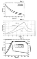
FIG. 4 is a graph showing changes in thickness of polymer batteries according to Example 1, Comparative Examples 1 and 2, measured after the polymer batteries are exposed to an elevated temperature. -
FIG. 5 is a graph showing a hotbox test result for a polymer battery with the MIT safety element according to Example 1. -
FIG. 6 is a graph showing a hotbox test result for a polymer battery without the MIT safety element according to Comparative Example 1. - Hereinafter, the present invention will be explained in more detail.
- According to the present invention, a battery is characterized by comprising a safety element connected between its positive and negative electrodes, the safety element comprising material having a Metal-Insulator Transition (MIT) characteristic where resistance abruptly drops at or above a certain temperature, as a way to sense the rise of a battery temperature and lower a charged state of the battery when the battery is exposed to an elevated temperature or the battery temperature rises due to external impact by pressure, nails or nippers, the rise of an ambient temperature or overcharging.
- The MIT characteristic is a material-specific characteristic which is presented by only materials including vanadium-based oxides such as VO, VO or V2O3 and Ti2O3 material or such materials to which an element such as Ba, La, etc. is added, where resistance of the materials abruptly changes according to a temperature (See
FIG. 2 ). The change in resistance is caused by phase transition of a crystalline structure between a metal and an insulator. - A difference between a safety element provided with material having an MIT characteristic (hereinafter briefly referred to as 'MIT safety element') and a Negative Temperature Coefficient (NTC) safety element, and the superiority of the MIT safety element over the NTC safety element are as follows:
- In contrast with general metals, material having an NTC characteristic (hereinafter briefly referred to as 'NTC material') is a semiconductor element having a negative temperature coefficient characteristic where resistance decrease with the rise of a temperature. A semiconductor is characterized in that its resistivity decreases with the increase of a temperature.
- Therefore, material having the MIT characteristic (hereinafter briefly referred to as 'MTT material') where phase transition occurs between a metal and an insulator is quite different from the NTC material.
- Also, dissimilarly to the MIT safety element of the present invention, it is difficult to apply the NTC safety element to a lithium ion secondary battery. Resistance change curves for ordinary NTC elements are shown in
FIG. 3 . - The NTC material has constant B of about 3000 to 4000 between a normal temperature and 150 °C , wherein resistance change is Ri = Ro exp{B(1/Ti - 1/To)} (Ri : resistance value at temperature Ti, Ro: resistance value at temperature To). The NTC material must have a resistance value of at least 10kΩ to 5kΩ so that it can operate without a problem such as current leakage at a normal temperature. In this case, the NTC material cannot flow enough electric current to safely protect a battery when a temperature rises. Accordingly, NTC material having low resistance at a normal temperature must be used in order to have a sufficient flow of electric current.
- However, when using NTC material having low resistance, for example having a resistance value of 1kΩ, at a normal temperature, an electric current of about 4mAflows at a voltage of 4.2 V (conventional secondary battery charging voltage) and a leakage current flows at a usual use temperature of the battery, leading to an overdischarged state. The battery in an overdischarged state exhibits a phenomenon in which performance of the battery abruptly deteriorates due to dissolution of Cu, etc., on a negative electrode. Moreover, a safety element consisting of NTC material having a low initial resistance value may collapse when an excess electric current flows at an elevated temperature, so that the safety element loses its capability as an NTC element and resistance increases. Such an element is transformed into an element not coinciding with the purpose of the present invention. Furthermore, since resistance of the NTC material does not decrease at a specific temperature, but decrease with the rise of a temperature, the NTC material has another disadvantage in that a leakage current becomes larger at a battery's usable temperature of 50 °C to 60 °C even in a case of NTC material having a very low leakage current at a normal temperature. As an example, 10kΩ-NTC material having constant B of 4000 shows about a leakage current of 2mAat a temperature of 60 °C.
- Contrary to the NTC material, MIT material experiences resistance change only in a specific temperature range and exhibits insulating characteristic having no influence on the battery at a battery's usable temperature of -20 °C to 60 °C. This phenomenon is attributed to structural change of crystalline and mostly occurs in vanadium-based materials such as VO, VO2 or V2O3. Also, since such materials have the width of resistance change in order of 102 or more, a sufficient electric current can flow through them only when a temperature rises to or above a critical point and thus enable a battery to rapidly become a discharged state, while no large current leakage occurs at a battery's usable temperature.
- A critical temperature of the MIT material for resistance change preferably lies in a range of 50 °C to 150 °C. On one hand, if resistance decreases at a temperature lower than 50 °C , a battery is discharged at its normal use temperature between 20 °C and 60 °C to reduce residual capacity of the battery. On the other hand, if resistance decreases at a temperature higher than 150 °C , this decrease of resistance has no influence on battery safety because the battery has been already swelled, fired or exploded due to external impact or environmental changes.
- Hereinafter, a description will be given for the structure of an MIT safety element and its connection to a battery.
- According to a first preferred embodiment of the present invention, an MIT safety element is constructed by connecting a metal lead wire having high electrical conductivity to any two places of MIT material having a certain form, respectively without bringing into contact with each other and the so-constructed MIT safety element is connected to positive and negative electrode terminals of a battery through the two lead wires. In order to strengthen durability of the MIT safety element, the MIT material portion of the MIT safety element may be sealed with packing material such as epoxy or glass.
- According to a second preferred embodiment of the present invention, an MIT safety element is constructed in the form of a chip and the so-constructed MIT safety element may be connected directly to positive and negative electrode terminals of a battery.
- According to a third preferred embodiment of the present invention, an MIT safety element is constructed in the form of a chip both ends of which is coated with metal films and the so-constructed MIT safety element may be connected directly to positive and negative electrode terminals of a battery.
- Insofar as positive and negative electrodes of a battery can be physically connected to each other, there is no limitation on the form and the position of the MIT safety element. For example, the safety element of the present invention may be provided inside or outside of a cell, or in a protective circuit (See
FIG. 1 ). - Hereinafter, operating mechanism of a battery with an MIT safety element of the present invention will be described in detail.
- If both positive and negative electrode terminals of a battery are connected to each other using MIT material inside or outside of the battery, an electric current does not flow through the MIT material between the positive and negative electrodes at a normal use temperature of the battery because the MIT material has very large resistance at that temperature. That is, the MIT material has no influence on the battery. However, if the battery is exposed to an elevated temperature or the battery temperature rises due to external impact and thus the battery is at or above a certain temperature, resistance of the MIT material abruptly drops and an electric current flows through the MIT material between the positive and negative electrodes, which causes the battery to be discharged and thus turns it into a safe state.
- Thus, when the MIT safety element is used in a battery, explosion or firing does not occur even if the battery is exposed to an elevated temperature. If a temperature is lowered again, resistance of the MIT material becomes larger again and an electric current does not flow any more, so that the battery can be used normally.
-
FIG. 1 illustrates two concrete states in which the MIT safety element is connected to a secondary battery in different manners in accordance with preferred embodiments of the present invention. - In these embodiments shown in
FIG. 1 , the MIT safety element of the present invention is connected to a polymer battery. - In general, a polymer battery has a laminate-type structure and includes one or more positive electrode plates and one or more negative electrode plates alternately laminated with the positive electrode plates. In this laminate-type battery, a positive electrode lead connecting the one or more positive electrode plates to each other and to the exterior of a cell, and a negative electrode lead connecting the one or more negative electrode plates to each other and to the exterior of the cell are connected to a power source located outside of a cell packing material.
- The MIT safety element of the present invention in which the MIT material is connected in parallel to a middle portion of a metal connector is connected between the positive and negative electrode leads inside or outside of the cell packing material.
- In a case of a lithium secondary battery, it fires or explodes when heated to or above 160 °C in a charged state. However, if the MIT material, resistance of which changes in a temperature range of 50 °C to 150 °C, is connected in parallel to positive and negative electrode terminals of the lithium secondary battery, an electric current flows toward the MIT material through which the electric current has not flowed hitherto to change the charged lithium secondary battery into a discharged state because resistance of the MIT material abruptly drops in the above-mentioned temperature range. That is, the lithium secondary battery will not fire or explode even if it is heated to or above 160 °C .
- Hereinafter, the present invention will be described in more detail with reference to the following Examples, which should not be construed as limiting the scope of the present invention.
- A cell was constructed such that its positive electrode consists of positive electrode active material (LiCoO2), a conducting agent and a binder (composition ratio of 95:2.5:2.5), and its negative electrode consists of negative electrode active material (carbon), a conducting agent and a binder (composition ratio of 94:2:4). An insulating membrane was interposed between the positive and negative electrodes, EC:EMC containing 1 M LiPF6 was used as an electrolyte, and a pouch was used as external packing material. In this way, a polymer battery was formed. An MIT safety element (vanadium-based oxide) having resistance of 25kΩ at a normal temperature was connected in parallel between the positive and negative electrode terminals of the so-formed polymer battery.
- (1) For an elevated temperature test, the polymer battery was placed in a oven, and change in thickness of the battery was measured while an oven temperature was raised from 25 °C to 90 °C for an hour, maintained at 90 °C for 5 hours and lowered to 25 for an hour. A result of this test is shown in
FIG. 4 . - (2) For a hotbox test, the battery to which the MIT safety element had been connected was charged up to 4.3 V, and then was placed in an oven. Thereafter, changes in voltage and temperature of the battery were measured while an oven temperature was raised from a normal temperature to 160 °C at a rate of 5 °C /min, maintained at 160 °C for an hour and lowered to a normal temperature by air cooling. A measurement result is shown in
FIG. 5 , and the battery did not explode. - Change in thickness at an elevated temperature was measured and a hotbox test was conducted in the same manner as that of Example 1, except that an MIT safety element was not connected to a polymer battery constructed as in Example 1. A measurement result of the change in thickness at an elevated temperature is shown in
FIG. 4 and a result of the hotbox test is shown inFIG. 6 . As the result of the hotbox test, the battery according to Comparative Example 1 exploded. - Chang in thickness at an elevated temperature was measured in the same manner as that of Example 1, except that, instead of an MIT safety element, an NTC element (constant B = 4000) having resistance of 10kΩat a normal temperature was connected in parallel to positive and negative electrode terminals of a polymer battery constructed as in Example 1. A measurement result is shown in
FIG. 4 . - In a case of the polymer battery with the NTC element, a leakage current of 2 mA was generated at a temperature of 60 °C .
- As described above, a battery with an MIT safety element according to the present invention is turned into a stable discharged state when it is exposed to an elevated temperature or a battery temperature rises due to external impact, etc., so that it can ensure its safety.
- The forgoing embodiments are merely exemplary and are not to be construed as limiting the present invention. The present teachings can be readily applied to other types of apparatuses. The description of the present invention is intended to be illustrative, and not to limit the scope of the claims. Many alternatives, modifications, and variations will be apparent to those skilled in the art.
Claims (7)
- A safety element for battery, comprising:a Metal-Insulator Transition (MIT) member connecting a positive electrode and a negative electrode of the battery to each other, the MIT member including an MIT material wherein the electrical resistance of the MIT material abruptly drops at or above a critical temperature by a phase transition from an insulator into a metal to allow electrical current to flow between the positive and negative electrodes,the critical temperature is in the range of from 50 °C to 150 °C, andthe MIT material is selected from the group consisting of VO, VO2, V2O3 and Ti2O3.
- The safety element as claimed in claim 1, wherein an element of Ba, or La is added to the MIT material.
- The safety element as claimed in claim 1, wherein a metal lead wire having high electrical conductivity is connected to any two places of the MIT member, respectively without bringing into contact with each other.
- The safety element as claimed in claim 1, wherein the MIT member is constructed in the form of a chip.
- The safety element as claimed in claim 1, wherein the MIT member is constructed in the form of a chip and both ends of the chip are coated with a metal film.
- The safety element as claimed in claim 1, wherein the MIT member is sealed with packing material.
- A battery including positive and negative electrode connected to each other through a safety element as claimed in any one of claims 1 to 6.
Applications Claiming Priority (2)
| Application Number | Priority Date | Filing Date | Title |
|---|---|---|---|
| KR20040035567 | 2004-05-19 | ||
| PCT/KR2005/001458 WO2005112182A1 (en) | 2004-05-19 | 2005-05-18 | Safety element for battery and battery with the same |
Publications (3)
| Publication Number | Publication Date |
|---|---|
| EP1749329A1 EP1749329A1 (en) | 2007-02-07 |
| EP1749329A4 EP1749329A4 (en) | 2011-01-19 |
| EP1749329B1 true EP1749329B1 (en) | 2015-10-07 |
Family
ID=35375540
Family Applications (1)
| Application Number | Title | Priority Date | Filing Date |
|---|---|---|---|
| EP05740769.4A Expired - Lifetime EP1749329B1 (en) | 2004-05-19 | 2005-05-18 | Safety element for battery and battery with the same |
Country Status (9)
| Country | Link |
|---|---|
| US (1) | US7629073B2 (en) |
| EP (1) | EP1749329B1 (en) |
| JP (1) | JP4990757B2 (en) |
| KR (2) | KR100959982B1 (en) |
| CN (1) | CN100486034C (en) |
| BR (1) | BRPI0509414B1 (en) |
| RU (1) | RU2323507C1 (en) |
| TW (1) | TWI258236B (en) |
| WO (1) | WO2005112182A1 (en) |
Families Citing this family (24)
| Publication number | Priority date | Publication date | Assignee | Title |
|---|---|---|---|---|
| KR100745354B1 (en) * | 2004-08-24 | 2007-08-02 | 주식회사 엘지화학 | Safety element for preventing overcharge of secondary battery and secondary battery combined with safety element |
| KR100734830B1 (en) * | 2005-01-14 | 2007-07-03 | 한국전자통신연구원 | Li secondary battery having discharge means |
| KR100786937B1 (en) * | 2005-07-20 | 2007-12-17 | 주식회사 엘지화학 | Apparatus for protection of secondary battery |
| US8673478B2 (en) * | 2007-02-05 | 2014-03-18 | Gas Technology Institute | Temperature dependent ionic gate |
| JP5657273B2 (en) | 2009-05-15 | 2015-01-21 | 日産自動車株式会社 | Multilayer battery, battery module, and method of manufacturing multilayer battery |
| US8535819B2 (en) | 2010-03-02 | 2013-09-17 | Lenovo (Singapore) Pte. Ltd. | Internally neutralizing a power source |
| JP5605314B2 (en) * | 2011-06-13 | 2014-10-15 | 株式会社Gsユアサ | Battery short-circuit element, secondary battery, and secondary battery system |
| US9178126B2 (en) * | 2012-07-05 | 2015-11-03 | Electronics And Telecommunications Research Institute | Thermoelectric elements using metal-insulator transition material |
| US9586489B2 (en) * | 2013-07-26 | 2017-03-07 | Lg Chem, Ltd. | Battery pack discharging device and method for discharging a battery pack |
| US10600959B2 (en) * | 2013-11-01 | 2020-03-24 | President And Fellows Of Harvard College | Dopant-driven phase transitions in correlated metal oxides |
| KR101446994B1 (en) * | 2013-12-09 | 2014-10-07 | 주식회사 모브릭 | Method for automatically breaking power at high temperature and high current based on Metal-Insulator Transition and switch for using the same |
| CN103700803A (en) * | 2014-01-16 | 2014-04-02 | 铂翔超精密模具科技(昆山)有限公司 | Battery protection system |
| KR101553372B1 (en) * | 2014-03-28 | 2015-09-15 | 전북대학교산학협력단 | Self-protective light emitting device |
| KR101595498B1 (en) * | 2014-04-17 | 2016-02-18 | 주식회사 아이티엠반도체 | Polymer battery cell and electronic device including the same |
| DE102017210369A1 (en) * | 2017-06-21 | 2018-12-27 | Lithium Energy and Power GmbH & Co. KG | battery cell |
| CN108305984A (en) * | 2018-01-31 | 2018-07-20 | 深圳市华源达科技有限公司 | A kind of housing of power cell |
| CN111276665B (en) * | 2018-12-04 | 2022-05-24 | 中信国安盟固利动力科技有限公司 | Soft package lithium ion battery |
| GB2590899B (en) | 2019-12-16 | 2023-08-16 | Dyson Technology Ltd | Hot-spot detection in electrical devices |
| CN113054329A (en) * | 2019-12-26 | 2021-06-29 | 荣盛盟固利新能源科技有限公司 | Lithium ion battery with overheating safety protection and overheating safety protection method thereof |
| CN111430655A (en) * | 2020-04-22 | 2020-07-17 | 福建飞毛腿动力科技有限公司 | Fusing protection structure with temperature shell fragment |
| KR102723746B1 (en) * | 2021-09-13 | 2024-10-31 | 주식회사 엘지에너지솔루션 | A pouch-type battery cell with a safety element between the electrode lead and the lead film |
| KR102943643B1 (en) | 2024-04-09 | 2026-03-25 | (주)씨앤비텍 | Secondary battery having thermal runaway preventing structure |
| KR102937662B1 (en) | 2024-04-09 | 2026-03-11 | (주)씨앤비텍 | Secondary battery having thermal runaway preventing structure |
| CN120978359B (en) * | 2025-10-21 | 2026-03-03 | 上海航天电源技术有限责任公司 | Voltage-triggered embedded safety device, control method, and battery for lithium-ion batteries |
Family Cites Families (28)
| Publication number | Priority date | Publication date | Assignee | Title |
|---|---|---|---|---|
| FR2050607A5 (en) * | 1969-06-18 | 1971-04-02 | Egorova Taisiya | Vanadium trioxide composition for thermistors |
| JPS5121160A (en) * | 1974-08-12 | 1976-02-20 | Marutei Suteeto Deibaishiizu L | KOTAISUITSUCHISOCHI |
| US4019097A (en) * | 1974-12-10 | 1977-04-19 | Westinghouse Electric Corporation | Circuit breaker with solid state passive overcurrent sensing device |
| GB1476779A (en) * | 1974-12-20 | 1977-06-16 | Matsushita Electric Industrial Co Ltd | Devices using ferroelectric materials |
| JPH0370698A (en) * | 1989-08-11 | 1991-03-26 | Naomasa Nomura | Head part rotating high performance airplane |
| JP3070698B2 (en) * | 1991-02-16 | 2000-07-31 | ティーディーケイ株式会社 | Current control element |
| JP3035677B2 (en) | 1991-09-13 | 2000-04-24 | 旭化成工業株式会社 | Secondary battery with safety element |
| JP3467311B2 (en) * | 1994-03-30 | 2003-11-17 | Tdk株式会社 | Lithium secondary battery |
| JPH09134714A (en) * | 1995-11-07 | 1997-05-20 | Wako Denshi Kk | Disc springs for safety devices |
| RU2074442C1 (en) * | 1995-06-13 | 1997-02-27 | Научное конструкторско-технологическое бюро химических источников тока при Новочеркасском государственном техническом университете | Fuse for cylindrical lithium storage cells |
| JPH09106804A (en) * | 1995-10-09 | 1997-04-22 | Wako Denshi Kk | Battery safety device |
| JP3305941B2 (en) * | 1996-01-22 | 2002-07-24 | 株式会社村田製作所 | Electronic components |
| JPH10144353A (en) * | 1996-11-15 | 1998-05-29 | Ngk Insulators Ltd | Lithium secondary battery |
| JPH10229222A (en) * | 1997-02-18 | 1998-08-25 | Tokin Corp | Semiconductor temperature switch element |
| JPH10302762A (en) * | 1997-02-28 | 1998-11-13 | Sumitomo Chem Co Ltd | Lithium secondary battery with thermal switch |
| JPH11111186A (en) | 1997-10-06 | 1999-04-23 | Toshiba Corp | Color picture tube and method of manufacturing the same |
| JPH11191436A (en) * | 1997-12-26 | 1999-07-13 | Hitachi Ltd | Storage protector |
| US6150051A (en) * | 1998-02-27 | 2000-11-21 | Telcordia Technologies, Inc. | Thermal switch for use in plastic batteries |
| JP4303801B2 (en) * | 1998-03-25 | 2009-07-29 | ワコー電子株式会社 | Secondary battery safety device |
| JPH11307069A (en) * | 1998-04-21 | 1999-11-05 | Murata Mfg Co Ltd | Electronic component and secondary battery pack |
| JP2001325943A (en) * | 2000-05-16 | 2001-11-22 | Toshiba Battery Co Ltd | Flat battery |
| KR100369069B1 (en) * | 1999-09-08 | 2003-01-24 | 삼성에스디아이 주식회사 | Pli battery |
| US6977343B2 (en) * | 2000-05-18 | 2005-12-20 | Sony Corporation | Heat-sensitive material and heat-sensitive element |
| JP3622676B2 (en) * | 2000-05-18 | 2005-02-23 | ソニーケミカル株式会社 | Thermal material and thermal element |
| JP2002118004A (en) * | 2000-10-11 | 2002-04-19 | Sharp Corp | Temperature-sensitive resistance change film, manufacturing method thereof, and infrared sensor using temperature-sensitive resistance change film |
| KR100433623B1 (en) * | 2001-09-17 | 2004-05-31 | 한국전자통신연구원 | Field effect transistor using sharp metal-insulator transition |
| JP4218792B2 (en) * | 2002-09-18 | 2009-02-04 | マクセル北陸精器株式会社 | Non-aqueous secondary battery |
| JP2005044626A (en) * | 2003-07-22 | 2005-02-17 | Sanyo Gs Soft Energy Co Ltd | Battery |
-
2005
- 2005-05-18 KR KR1020050041480A patent/KR100959982B1/en not_active Expired - Lifetime
- 2005-05-18 WO PCT/KR2005/001458 patent/WO2005112182A1/en not_active Ceased
- 2005-05-18 RU RU2006145031/09A patent/RU2323507C1/en active
- 2005-05-18 EP EP05740769.4A patent/EP1749329B1/en not_active Expired - Lifetime
- 2005-05-18 BR BRPI0509414A patent/BRPI0509414B1/en active IP Right Grant
- 2005-05-18 CN CNB2005800111605A patent/CN100486034C/en not_active Expired - Lifetime
- 2005-05-18 JP JP2007507251A patent/JP4990757B2/en not_active Expired - Lifetime
- 2005-05-19 TW TW094116320A patent/TWI258236B/en not_active IP Right Cessation
- 2005-05-19 US US11/132,468 patent/US7629073B2/en active Active
-
2008
- 2008-10-29 KR KR1020080106633A patent/KR101121282B1/en not_active Expired - Lifetime
Also Published As
| Publication number | Publication date |
|---|---|
| EP1749329A1 (en) | 2007-02-07 |
| BRPI0509414A (en) | 2007-09-04 |
| CN100486034C (en) | 2009-05-06 |
| KR101121282B1 (en) | 2012-03-23 |
| EP1749329A4 (en) | 2011-01-19 |
| KR100959982B1 (en) | 2010-05-27 |
| US7629073B2 (en) | 2009-12-08 |
| TWI258236B (en) | 2006-07-11 |
| TW200603457A (en) | 2006-01-16 |
| WO2005112182A1 (en) | 2005-11-24 |
| US20050260486A1 (en) | 2005-11-24 |
| JP2007533074A (en) | 2007-11-15 |
| BRPI0509414B1 (en) | 2016-05-17 |
| KR20060047988A (en) | 2006-05-18 |
| JP4990757B2 (en) | 2012-08-01 |
| CN1943073A (en) | 2007-04-04 |
| RU2323507C1 (en) | 2008-04-27 |
| KR20080099227A (en) | 2008-11-12 |
Similar Documents
| Publication | Publication Date | Title |
|---|---|---|
| US7629073B2 (en) | Safety element for battery and battery with the same | |
| JP5723925B2 (en) | Secondary battery protection circuit and secondary battery having the same | |
| TWI262615B (en) | Electrochemical cell comprising electrode lead with protector element | |
| US20040110061A1 (en) | Rechargeable, galvanic element with at least one lithium-intercalating electrode | |
| US20110086253A1 (en) | Electrochemical cell with an irreversible fuse | |
| JP4537355B2 (en) | Secondary battery with PTC element | |
| KR101208570B1 (en) | Novel protection circuit module and battery pack including the same | |
| CN100547850C (en) | Safety device for preventing overcharge of secondary battery and secondary battery having the same | |
| US20240055875A1 (en) | Secondary battery capable of preventing overcharge, and charging method thereof | |
| JP3574843B2 (en) | Lithium secondary battery with safety mechanism | |
| KR20040037547A (en) | Secondary battery pack | |
| KR20090098522A (en) | Secondary battery | |
| JP2008527670A (en) | Lithium secondary battery having charge discharging means | |
| KR100502354B1 (en) | Pouched-type lithium secondary battery | |
| KR100577489B1 (en) | Secondary battery with electrode terminal having PTC characteristics | |
| KR200302619Y1 (en) | Secondary battery pack | |
| KR101023850B1 (en) | Secondary protection element for secondary battery | |
| KR20070033853A (en) | Safety element for preventing overcharge of secondary battery and secondary battery combined with safety element |
Legal Events
| Date | Code | Title | Description |
|---|---|---|---|
| PUAI | Public reference made under article 153(3) epc to a published international application that has entered the european phase |
Free format text: ORIGINAL CODE: 0009012 |
|
| 17P | Request for examination filed |
Effective date: 20061011 |
|
| AK | Designated contracting states |
Kind code of ref document: A1 Designated state(s): AT BE BG CH CY CZ DE DK EE ES FI FR GB GR HU IE IS IT LI LT LU MC NL PL PT RO SE SI SK TR |
|
| DAX | Request for extension of the european patent (deleted) | ||
| RIN1 | Information on inventor provided before grant (corrected) |
Inventor name: CHANG, SUNG-KYUN,201-201 SONGGANGMAUL APT Inventor name: LEE, JAE-HYUN,109-1805, CHEONGGU NARAE APT Inventor name: CHO, JEONG-JU Inventor name: HA, SOO-HYUN,1902, YEONSAN SSANGYONG APT. Inventor name: BANG, EUI-YONG Inventor name: SHIN, SUN-SIK Inventor name: JANG, MIN-CHUL,8-703, SINDONG-A APARTMENT Inventor name: LEE, JOON-HWAN |
|
| A4 | Supplementary search report drawn up and despatched |
Effective date: 20101221 |
|
| 17Q | First examination report despatched |
Effective date: 20110530 |
|
| REG | Reference to a national code |
Ref country code: DE Ref legal event code: R079 Ref document number: 602005047639 Country of ref document: DE Free format text: PREVIOUS MAIN CLASS: H01M0010500000 Ipc: H01M0010000000 |
|
| RIC1 | Information provided on ipc code assigned before grant |
Ipc: H01M 10/00 20060101AFI20150319BHEP |
|
| GRAP | Despatch of communication of intention to grant a patent |
Free format text: ORIGINAL CODE: EPIDOSNIGR1 |
|
| INTG | Intention to grant announced |
Effective date: 20150729 |
|
| GRAS | Grant fee paid |
Free format text: ORIGINAL CODE: EPIDOSNIGR3 |
|
| GRAA | (expected) grant |
Free format text: ORIGINAL CODE: 0009210 |
|
| AK | Designated contracting states |
Kind code of ref document: B1 Designated state(s): AT BE BG CH CY CZ DE DK EE ES FI FR GB GR HU IE IS IT LI LT LU MC NL PL PT RO SE SI SK TR |
|
| REG | Reference to a national code |
Ref country code: GB Ref legal event code: FG4D |
|
| REG | Reference to a national code |
Ref country code: AT Ref legal event code: REF Ref document number: 754228 Country of ref document: AT Kind code of ref document: T Effective date: 20151015 Ref country code: CH Ref legal event code: EP |
|
| REG | Reference to a national code |
Ref country code: IE Ref legal event code: FG4D |
|
| REG | Reference to a national code |
Ref country code: DE Ref legal event code: R096 Ref document number: 602005047639 Country of ref document: DE |
|
| REG | Reference to a national code |
Ref country code: NL Ref legal event code: MP Effective date: 20151007 |
|
| REG | Reference to a national code |
Ref country code: AT Ref legal event code: MK05 Ref document number: 754228 Country of ref document: AT Kind code of ref document: T Effective date: 20151007 |
|
| REG | Reference to a national code |
Ref country code: LT Ref legal event code: MG4D |
|
| REG | Reference to a national code |
Ref country code: FR Ref legal event code: PLFP Year of fee payment: 12 |
|
| PG25 | Lapsed in a contracting state [announced via postgrant information from national office to epo] |
Ref country code: ES Free format text: LAPSE BECAUSE OF FAILURE TO SUBMIT A TRANSLATION OF THE DESCRIPTION OR TO PAY THE FEE WITHIN THE PRESCRIBED TIME-LIMIT Effective date: 20151007 Ref country code: IS Free format text: LAPSE BECAUSE OF FAILURE TO SUBMIT A TRANSLATION OF THE DESCRIPTION OR TO PAY THE FEE WITHIN THE PRESCRIBED TIME-LIMIT Effective date: 20160207 Ref country code: NL Free format text: LAPSE BECAUSE OF FAILURE TO SUBMIT A TRANSLATION OF THE DESCRIPTION OR TO PAY THE FEE WITHIN THE PRESCRIBED TIME-LIMIT Effective date: 20151007 Ref country code: LT Free format text: LAPSE BECAUSE OF FAILURE TO SUBMIT A TRANSLATION OF THE DESCRIPTION OR TO PAY THE FEE WITHIN THE PRESCRIBED TIME-LIMIT Effective date: 20151007 Ref country code: IT Free format text: LAPSE BECAUSE OF FAILURE TO SUBMIT A TRANSLATION OF THE DESCRIPTION OR TO PAY THE FEE WITHIN THE PRESCRIBED TIME-LIMIT Effective date: 20151007 |
|
| PG25 | Lapsed in a contracting state [announced via postgrant information from national office to epo] |
Ref country code: AT Free format text: LAPSE BECAUSE OF FAILURE TO SUBMIT A TRANSLATION OF THE DESCRIPTION OR TO PAY THE FEE WITHIN THE PRESCRIBED TIME-LIMIT Effective date: 20151007 Ref country code: FI Free format text: LAPSE BECAUSE OF FAILURE TO SUBMIT A TRANSLATION OF THE DESCRIPTION OR TO PAY THE FEE WITHIN THE PRESCRIBED TIME-LIMIT Effective date: 20151007 Ref country code: GR Free format text: LAPSE BECAUSE OF FAILURE TO SUBMIT A TRANSLATION OF THE DESCRIPTION OR TO PAY THE FEE WITHIN THE PRESCRIBED TIME-LIMIT Effective date: 20160108 Ref country code: SE Free format text: LAPSE BECAUSE OF FAILURE TO SUBMIT A TRANSLATION OF THE DESCRIPTION OR TO PAY THE FEE WITHIN THE PRESCRIBED TIME-LIMIT Effective date: 20151007 Ref country code: PL Free format text: LAPSE BECAUSE OF FAILURE TO SUBMIT A TRANSLATION OF THE DESCRIPTION OR TO PAY THE FEE WITHIN THE PRESCRIBED TIME-LIMIT Effective date: 20151007 Ref country code: PT Free format text: LAPSE BECAUSE OF FAILURE TO SUBMIT A TRANSLATION OF THE DESCRIPTION OR TO PAY THE FEE WITHIN THE PRESCRIBED TIME-LIMIT Effective date: 20160208 |
|
| REG | Reference to a national code |
Ref country code: DE Ref legal event code: R097 Ref document number: 602005047639 Country of ref document: DE |
|
| PG25 | Lapsed in a contracting state [announced via postgrant information from national office to epo] |
Ref country code: CZ Free format text: LAPSE BECAUSE OF FAILURE TO SUBMIT A TRANSLATION OF THE DESCRIPTION OR TO PAY THE FEE WITHIN THE PRESCRIBED TIME-LIMIT Effective date: 20151007 |
|
| PLBE | No opposition filed within time limit |
Free format text: ORIGINAL CODE: 0009261 |
|
| STAA | Information on the status of an ep patent application or granted ep patent |
Free format text: STATUS: NO OPPOSITION FILED WITHIN TIME LIMIT |
|
| PG25 | Lapsed in a contracting state [announced via postgrant information from national office to epo] |
Ref country code: BE Free format text: LAPSE BECAUSE OF NON-PAYMENT OF DUE FEES Effective date: 20160531 Ref country code: SK Free format text: LAPSE BECAUSE OF FAILURE TO SUBMIT A TRANSLATION OF THE DESCRIPTION OR TO PAY THE FEE WITHIN THE PRESCRIBED TIME-LIMIT Effective date: 20151007 Ref country code: RO Free format text: LAPSE BECAUSE OF FAILURE TO SUBMIT A TRANSLATION OF THE DESCRIPTION OR TO PAY THE FEE WITHIN THE PRESCRIBED TIME-LIMIT Effective date: 20151007 Ref country code: EE Free format text: LAPSE BECAUSE OF FAILURE TO SUBMIT A TRANSLATION OF THE DESCRIPTION OR TO PAY THE FEE WITHIN THE PRESCRIBED TIME-LIMIT Effective date: 20151007 Ref country code: DK Free format text: LAPSE BECAUSE OF FAILURE TO SUBMIT A TRANSLATION OF THE DESCRIPTION OR TO PAY THE FEE WITHIN THE PRESCRIBED TIME-LIMIT Effective date: 20151007 |
|
| 26N | No opposition filed |
Effective date: 20160708 |
|
| PG25 | Lapsed in a contracting state [announced via postgrant information from national office to epo] |
Ref country code: SI Free format text: LAPSE BECAUSE OF FAILURE TO SUBMIT A TRANSLATION OF THE DESCRIPTION OR TO PAY THE FEE WITHIN THE PRESCRIBED TIME-LIMIT Effective date: 20151007 |
|
| PG25 | Lapsed in a contracting state [announced via postgrant information from national office to epo] |
Ref country code: BE Free format text: LAPSE BECAUSE OF FAILURE TO SUBMIT A TRANSLATION OF THE DESCRIPTION OR TO PAY THE FEE WITHIN THE PRESCRIBED TIME-LIMIT Effective date: 20151007 Ref country code: LU Free format text: LAPSE BECAUSE OF FAILURE TO SUBMIT A TRANSLATION OF THE DESCRIPTION OR TO PAY THE FEE WITHIN THE PRESCRIBED TIME-LIMIT Effective date: 20160518 |
|
| REG | Reference to a national code |
Ref country code: CH Ref legal event code: PL |
|
| PG25 | Lapsed in a contracting state [announced via postgrant information from national office to epo] |
Ref country code: CH Free format text: LAPSE BECAUSE OF NON-PAYMENT OF DUE FEES Effective date: 20160531 Ref country code: LI Free format text: LAPSE BECAUSE OF NON-PAYMENT OF DUE FEES Effective date: 20160531 |
|
| REG | Reference to a national code |
Ref country code: IE Ref legal event code: MM4A |
|
| REG | Reference to a national code |
Ref country code: FR Ref legal event code: PLFP Year of fee payment: 13 |
|
| PG25 | Lapsed in a contracting state [announced via postgrant information from national office to epo] |
Ref country code: IE Free format text: LAPSE BECAUSE OF NON-PAYMENT OF DUE FEES Effective date: 20160518 |
|
| REG | Reference to a national code |
Ref country code: FR Ref legal event code: PLFP Year of fee payment: 14 |
|
| PG25 | Lapsed in a contracting state [announced via postgrant information from national office to epo] |
Ref country code: CY Free format text: LAPSE BECAUSE OF FAILURE TO SUBMIT A TRANSLATION OF THE DESCRIPTION OR TO PAY THE FEE WITHIN THE PRESCRIBED TIME-LIMIT Effective date: 20151007 Ref country code: HU Free format text: LAPSE BECAUSE OF FAILURE TO SUBMIT A TRANSLATION OF THE DESCRIPTION OR TO PAY THE FEE WITHIN THE PRESCRIBED TIME-LIMIT; INVALID AB INITIO Effective date: 20050518 |
|
| PG25 | Lapsed in a contracting state [announced via postgrant information from national office to epo] |
Ref country code: MC Free format text: LAPSE BECAUSE OF FAILURE TO SUBMIT A TRANSLATION OF THE DESCRIPTION OR TO PAY THE FEE WITHIN THE PRESCRIBED TIME-LIMIT Effective date: 20151007 Ref country code: TR Free format text: LAPSE BECAUSE OF FAILURE TO SUBMIT A TRANSLATION OF THE DESCRIPTION OR TO PAY THE FEE WITHIN THE PRESCRIBED TIME-LIMIT Effective date: 20151007 |
|
| PG25 | Lapsed in a contracting state [announced via postgrant information from national office to epo] |
Ref country code: BG Free format text: LAPSE BECAUSE OF FAILURE TO SUBMIT A TRANSLATION OF THE DESCRIPTION OR TO PAY THE FEE WITHIN THE PRESCRIBED TIME-LIMIT Effective date: 20151007 |
|
| REG | Reference to a national code |
Ref country code: DE Ref legal event code: R081 Ref document number: 602005047639 Country of ref document: DE Owner name: LG ENERGY SOLUTION LTD., KR Free format text: FORMER OWNER: LG CHEM. LTD., SEOUL, KR Ref country code: DE Ref legal event code: R081 Ref document number: 602005047639 Country of ref document: DE Owner name: LG ENERGY SOLUTION, LTD., KR Free format text: FORMER OWNER: LG CHEM. LTD., SEOUL, KR |
|
| P01 | Opt-out of the competence of the unified patent court (upc) registered |
Effective date: 20230408 |
|
| REG | Reference to a national code |
Ref country code: GB Ref legal event code: 732E Free format text: REGISTERED BETWEEN 20230824 AND 20230831 |
|
| REG | Reference to a national code |
Ref country code: DE Ref legal event code: R081 Ref document number: 602005047639 Country of ref document: DE Owner name: LG ENERGY SOLUTION, LTD., KR Free format text: FORMER OWNER: LG ENERGY SOLUTION LTD., SEOUL, KR |
|
| PGFP | Annual fee paid to national office [announced via postgrant information from national office to epo] |
Ref country code: GB Payment date: 20240422 Year of fee payment: 20 |
|
| PGFP | Annual fee paid to national office [announced via postgrant information from national office to epo] |
Ref country code: DE Payment date: 20240422 Year of fee payment: 20 |
|
| PGFP | Annual fee paid to national office [announced via postgrant information from national office to epo] |
Ref country code: FR Payment date: 20240423 Year of fee payment: 20 |
|
| REG | Reference to a national code |
Ref country code: DE Ref legal event code: R071 Ref document number: 602005047639 Country of ref document: DE |
|
| REG | Reference to a national code |
Ref country code: GB Ref legal event code: PE20 Expiry date: 20250517 |
|
| PG25 | Lapsed in a contracting state [announced via postgrant information from national office to epo] |
Ref country code: GB Free format text: LAPSE BECAUSE OF EXPIRATION OF PROTECTION Effective date: 20250517 |