EP1748819B1 - Device for decoupling and/or desynchronizing neural brain activity - Google Patents
Device for decoupling and/or desynchronizing neural brain activity Download PDFInfo
- Publication number
- EP1748819B1 EP1748819B1 EP05745186.6A EP05745186A EP1748819B1 EP 1748819 B1 EP1748819 B1 EP 1748819B1 EP 05745186 A EP05745186 A EP 05745186A EP 1748819 B1 EP1748819 B1 EP 1748819B1
- Authority
- EP
- European Patent Office
- Prior art keywords
- stimulation
- control
- signals
- decoupled
- signal
- Prior art date
- Legal status (The legal status is an assumption and is not a legal conclusion. Google has not performed a legal analysis and makes no representation as to the accuracy of the status listed.)
- Not-in-force
Links
- 230000001537 neural effect Effects 0.000 title claims description 141
- 230000007177 brain activity Effects 0.000 title claims description 8
- 230000000638 stimulation Effects 0.000 claims description 445
- 230000000694 effects Effects 0.000 claims description 92
- 230000001575 pathological effect Effects 0.000 claims description 57
- 238000005259 measurement Methods 0.000 claims description 56
- 201000010099 disease Diseases 0.000 claims description 53
- 208000037265 diseases, disorders, signs and symptoms Diseases 0.000 claims description 53
- 238000000034 method Methods 0.000 claims description 51
- 238000012545 processing Methods 0.000 claims description 36
- 230000001934 delay Effects 0.000 claims description 35
- 238000004458 analytical method Methods 0.000 claims description 29
- 238000004422 calculation algorithm Methods 0.000 claims description 14
- 238000001914 filtration Methods 0.000 claims description 14
- 230000008569 process Effects 0.000 claims description 12
- 230000009466 transformation Effects 0.000 claims description 8
- 238000011161 development Methods 0.000 claims description 7
- 230000006870 function Effects 0.000 claims description 7
- 210000003205 muscle Anatomy 0.000 claims description 7
- 230000003111 delayed effect Effects 0.000 claims description 5
- 238000002955 isolation Methods 0.000 claims description 5
- 230000001105 regulatory effect Effects 0.000 claims description 5
- 230000004936 stimulating effect Effects 0.000 claims description 5
- 230000004913 activation Effects 0.000 claims description 3
- 210000004126 nerve fiber Anatomy 0.000 claims description 3
- 230000003321 amplification Effects 0.000 claims description 2
- 238000003199 nucleic acid amplification method Methods 0.000 claims description 2
- 238000000844 transformation Methods 0.000 claims description 2
- 230000001276 controlling effect Effects 0.000 claims 3
- 230000001131 transforming effect Effects 0.000 claims 2
- 230000003252 repetitive effect Effects 0.000 claims 1
- 210000002569 neuron Anatomy 0.000 description 183
- 210000004556 brain Anatomy 0.000 description 30
- 230000001360 synchronised effect Effects 0.000 description 28
- 238000010168 coupling process Methods 0.000 description 27
- 238000005859 coupling reaction Methods 0.000 description 27
- 230000008878 coupling Effects 0.000 description 26
- 208000024891 symptom Diseases 0.000 description 22
- 230000000306 recurrent effect Effects 0.000 description 15
- 230000003287 optical effect Effects 0.000 description 14
- 230000033764 rhythmic process Effects 0.000 description 14
- 206010044565 Tremor Diseases 0.000 description 13
- 230000001020 rhythmical effect Effects 0.000 description 13
- 230000007246 mechanism Effects 0.000 description 11
- 208000018737 Parkinson disease Diseases 0.000 description 9
- 238000002513 implantation Methods 0.000 description 9
- 210000001103 thalamus Anatomy 0.000 description 9
- 238000001514 detection method Methods 0.000 description 8
- 230000002123 temporal effect Effects 0.000 description 8
- 206010015037 epilepsy Diseases 0.000 description 7
- 239000000835 fiber Substances 0.000 description 7
- 238000010304 firing Methods 0.000 description 7
- 210000000337 motor cortex Anatomy 0.000 description 7
- 210000001519 tissue Anatomy 0.000 description 7
- 230000006978 adaptation Effects 0.000 description 6
- 210000004227 basal ganglia Anatomy 0.000 description 6
- 230000008901 benefit Effects 0.000 description 6
- 208000010118 dystonia Diseases 0.000 description 6
- 208000014094 Dystonic disease Diseases 0.000 description 5
- 208000021384 Obsessive-Compulsive disease Diseases 0.000 description 5
- 230000008859 change Effects 0.000 description 5
- 201000006517 essential tremor Diseases 0.000 description 5
- 230000003993 interaction Effects 0.000 description 5
- 230000002969 morbid Effects 0.000 description 5
- 210000004281 subthalamic nucleus Anatomy 0.000 description 5
- 230000001629 suppression Effects 0.000 description 5
- 206010008754 Choreoathetosis Diseases 0.000 description 4
- 208000012902 Nervous system disease Diseases 0.000 description 4
- 208000025966 Neurological disease Diseases 0.000 description 4
- 210000003484 anatomy Anatomy 0.000 description 4
- 230000033228 biological regulation Effects 0.000 description 4
- 230000000926 neurological effect Effects 0.000 description 4
- 230000000737 periodic effect Effects 0.000 description 4
- 208000020016 psychiatric disease Diseases 0.000 description 4
- 230000009467 reduction Effects 0.000 description 4
- 230000004044 response Effects 0.000 description 4
- 230000003595 spectral effect Effects 0.000 description 4
- 230000000451 tissue damage Effects 0.000 description 4
- 231100000827 tissue damage Toxicity 0.000 description 4
- 238000009826 distribution Methods 0.000 description 3
- 238000012360 testing method Methods 0.000 description 3
- 230000001225 therapeutic effect Effects 0.000 description 3
- 206010008111 Cerebral haemorrhage Diseases 0.000 description 2
- 230000036982 action potential Effects 0.000 description 2
- 230000002146 bilateral effect Effects 0.000 description 2
- 230000015572 biosynthetic process Effects 0.000 description 2
- 210000005013 brain tissue Anatomy 0.000 description 2
- 238000004364 calculation method Methods 0.000 description 2
- 230000002490 cerebral effect Effects 0.000 description 2
- 230000018109 developmental process Effects 0.000 description 2
- 238000012886 linear function Methods 0.000 description 2
- 230000010534 mechanism of action Effects 0.000 description 2
- 201000006417 multiple sclerosis Diseases 0.000 description 2
- 210000001009 nucleus accumben Anatomy 0.000 description 2
- 230000002085 persistent effect Effects 0.000 description 2
- 230000035790 physiological processes and functions Effects 0.000 description 2
- 230000002441 reversible effect Effects 0.000 description 2
- 210000002023 somite Anatomy 0.000 description 2
- 238000003860 storage Methods 0.000 description 2
- 238000001356 surgical procedure Methods 0.000 description 2
- 230000001052 transient effect Effects 0.000 description 2
- 238000012800 visualization Methods 0.000 description 2
- 238000012935 Averaging Methods 0.000 description 1
- 241000459479 Capsula Species 0.000 description 1
- 206010008025 Cerebellar ataxia Diseases 0.000 description 1
- 206010013886 Dysaesthesia Diseases 0.000 description 1
- 206010013887 Dysarthria Diseases 0.000 description 1
- 240000003517 Elaeocarpus dentatus Species 0.000 description 1
- 206010071229 Procedural haemorrhage Diseases 0.000 description 1
- 208000027418 Wounds and injury Diseases 0.000 description 1
- 238000003491 array Methods 0.000 description 1
- 210000001367 artery Anatomy 0.000 description 1
- 238000013528 artificial neural network Methods 0.000 description 1
- 230000006931 brain damage Effects 0.000 description 1
- 231100000874 brain damage Toxicity 0.000 description 1
- 208000029028 brain injury Diseases 0.000 description 1
- 230000009172 bursting Effects 0.000 description 1
- 210000001159 caudate nucleus Anatomy 0.000 description 1
- 210000001638 cerebellum Anatomy 0.000 description 1
- 210000003710 cerebral cortex Anatomy 0.000 description 1
- 238000012790 confirmation Methods 0.000 description 1
- 230000006378 damage Effects 0.000 description 1
- 238000007405 data analysis Methods 0.000 description 1
- 230000001419 dependent effect Effects 0.000 description 1
- 238000009795 derivation Methods 0.000 description 1
- 238000013461 design Methods 0.000 description 1
- 238000003745 diagnosis Methods 0.000 description 1
- 239000003814 drug Substances 0.000 description 1
- 229940079593 drug Drugs 0.000 description 1
- 230000004064 dysfunction Effects 0.000 description 1
- 238000005265 energy consumption Methods 0.000 description 1
- 230000002349 favourable effect Effects 0.000 description 1
- 230000007274 generation of a signal involved in cell-cell signaling Effects 0.000 description 1
- 210000001905 globus pallidus Anatomy 0.000 description 1
- 239000007943 implant Substances 0.000 description 1
- 230000006872 improvement Effects 0.000 description 1
- 208000014674 injury Diseases 0.000 description 1
- 210000002425 internal capsule Anatomy 0.000 description 1
- 230000007794 irritation Effects 0.000 description 1
- 230000003902 lesion Effects 0.000 description 1
- 230000005923 long-lasting effect Effects 0.000 description 1
- 238000004519 manufacturing process Methods 0.000 description 1
- 230000004048 modification Effects 0.000 description 1
- 238000012986 modification Methods 0.000 description 1
- 230000003387 muscular Effects 0.000 description 1
- 230000010355 oscillation Effects 0.000 description 1
- 230000003534 oscillatory effect Effects 0.000 description 1
- 208000035824 paresthesia Diseases 0.000 description 1
- 230000002093 peripheral effect Effects 0.000 description 1
- 230000001766 physiological effect Effects 0.000 description 1
- 210000000976 primary motor cortex Anatomy 0.000 description 1
- 201000000980 schizophrenia Diseases 0.000 description 1
- 238000000926 separation method Methods 0.000 description 1
- 238000010561 standard procedure Methods 0.000 description 1
- 210000004001 thalamic nuclei Anatomy 0.000 description 1
- 238000002560 therapeutic procedure Methods 0.000 description 1
Images


Classifications
-
- A—HUMAN NECESSITIES
- A61—MEDICAL OR VETERINARY SCIENCE; HYGIENE
- A61N—ELECTROTHERAPY; MAGNETOTHERAPY; RADIATION THERAPY; ULTRASOUND THERAPY
- A61N1/00—Electrotherapy; Circuits therefor
- A61N1/18—Applying electric currents by contact electrodes
- A61N1/32—Applying electric currents by contact electrodes alternating or intermittent currents
- A61N1/36—Applying electric currents by contact electrodes alternating or intermittent currents for stimulation
- A61N1/3605—Implantable neurostimulators for stimulating central or peripheral nerve system
- A61N1/3606—Implantable neurostimulators for stimulating central or peripheral nerve system adapted for a particular treatment
- A61N1/36082—Cognitive or psychiatric applications, e.g. dementia or Alzheimer's disease
-
- A—HUMAN NECESSITIES
- A61—MEDICAL OR VETERINARY SCIENCE; HYGIENE
- A61N—ELECTROTHERAPY; MAGNETOTHERAPY; RADIATION THERAPY; ULTRASOUND THERAPY
- A61N1/00—Electrotherapy; Circuits therefor
- A61N1/18—Applying electric currents by contact electrodes
- A61N1/32—Applying electric currents by contact electrodes alternating or intermittent currents
- A61N1/36—Applying electric currents by contact electrodes alternating or intermittent currents for stimulation
- A61N1/3605—Implantable neurostimulators for stimulating central or peripheral nerve system
- A61N1/3606—Implantable neurostimulators for stimulating central or peripheral nerve system adapted for a particular treatment
- A61N1/36067—Movement disorders, e.g. tremor or Parkinson disease
-
- A—HUMAN NECESSITIES
- A61—MEDICAL OR VETERINARY SCIENCE; HYGIENE
- A61N—ELECTROTHERAPY; MAGNETOTHERAPY; RADIATION THERAPY; ULTRASOUND THERAPY
- A61N1/00—Electrotherapy; Circuits therefor
- A61N1/18—Applying electric currents by contact electrodes
- A61N1/32—Applying electric currents by contact electrodes alternating or intermittent currents
- A61N1/36—Applying electric currents by contact electrodes alternating or intermittent currents for stimulation
- A61N1/3605—Implantable neurostimulators for stimulating central or peripheral nerve system
- A61N1/36128—Control systems
- A61N1/36135—Control systems using physiological parameters
-
- A—HUMAN NECESSITIES
- A61—MEDICAL OR VETERINARY SCIENCE; HYGIENE
- A61N—ELECTROTHERAPY; MAGNETOTHERAPY; RADIATION THERAPY; ULTRASOUND THERAPY
- A61N1/00—Electrotherapy; Circuits therefor
- A61N1/18—Applying electric currents by contact electrodes
- A61N1/32—Applying electric currents by contact electrodes alternating or intermittent currents
- A61N1/36—Applying electric currents by contact electrodes alternating or intermittent currents for stimulation
- A61N1/3605—Implantable neurostimulators for stimulating central or peripheral nerve system
- A61N1/36128—Control systems
- A61N1/36146—Control systems specified by the stimulation parameters
-
- A—HUMAN NECESSITIES
- A61—MEDICAL OR VETERINARY SCIENCE; HYGIENE
- A61B—DIAGNOSIS; SURGERY; IDENTIFICATION
- A61B5/00—Measuring for diagnostic purposes; Identification of persons
- A61B5/0002—Remote monitoring of patients using telemetry, e.g. transmission of vital signals via a communication network
- A61B5/0004—Remote monitoring of patients using telemetry, e.g. transmission of vital signals via a communication network characterised by the type of physiological signal transmitted
- A61B5/0006—ECG or EEG signals
-
- A—HUMAN NECESSITIES
- A61—MEDICAL OR VETERINARY SCIENCE; HYGIENE
- A61B—DIAGNOSIS; SURGERY; IDENTIFICATION
- A61B5/00—Measuring for diagnostic purposes; Identification of persons
- A61B5/24—Detecting, measuring or recording bioelectric or biomagnetic signals of the body or parts thereof
- A61B5/316—Modalities, i.e. specific diagnostic methods
- A61B5/369—Electroencephalography [EEG]
- A61B5/372—Analysis of electroencephalograms
- A61B5/374—Detecting the frequency distribution of signals, e.g. detecting delta, theta, alpha, beta or gamma waves
-
- A—HUMAN NECESSITIES
- A61—MEDICAL OR VETERINARY SCIENCE; HYGIENE
- A61B—DIAGNOSIS; SURGERY; IDENTIFICATION
- A61B5/00—Measuring for diagnostic purposes; Identification of persons
- A61B5/40—Detecting, measuring or recording for evaluating the nervous system
- A61B5/4076—Diagnosing or monitoring particular conditions of the nervous system
- A61B5/4082—Diagnosing or monitoring movement diseases, e.g. Parkinson, Huntington or Tourette
-
- A—HUMAN NECESSITIES
- A61—MEDICAL OR VETERINARY SCIENCE; HYGIENE
- A61B—DIAGNOSIS; SURGERY; IDENTIFICATION
- A61B5/00—Measuring for diagnostic purposes; Identification of persons
- A61B5/72—Signal processing specially adapted for physiological signals or for diagnostic purposes
- A61B5/7225—Details of analog processing, e.g. isolation amplifier, gain or sensitivity adjustment, filtering, baseline or drift compensation
-
- A—HUMAN NECESSITIES
- A61—MEDICAL OR VETERINARY SCIENCE; HYGIENE
- A61B—DIAGNOSIS; SURGERY; IDENTIFICATION
- A61B5/00—Measuring for diagnostic purposes; Identification of persons
- A61B5/72—Signal processing specially adapted for physiological signals or for diagnostic purposes
- A61B5/7235—Details of waveform analysis
- A61B5/7253—Details of waveform analysis characterised by using transforms
- A61B5/726—Details of waveform analysis characterised by using transforms using Wavelet transforms
-
- A—HUMAN NECESSITIES
- A61—MEDICAL OR VETERINARY SCIENCE; HYGIENE
- A61N—ELECTROTHERAPY; MAGNETOTHERAPY; RADIATION THERAPY; ULTRASOUND THERAPY
- A61N1/00—Electrotherapy; Circuits therefor
- A61N1/02—Details
- A61N1/04—Electrodes
- A61N1/05—Electrodes for implantation or insertion into the body, e.g. heart electrode
- A61N1/0551—Spinal or peripheral nerve electrodes
-
- A—HUMAN NECESSITIES
- A61—MEDICAL OR VETERINARY SCIENCE; HYGIENE
- A61N—ELECTROTHERAPY; MAGNETOTHERAPY; RADIATION THERAPY; ULTRASOUND THERAPY
- A61N1/00—Electrotherapy; Circuits therefor
- A61N1/02—Details
- A61N1/04—Electrodes
- A61N1/06—Electrodes for high-frequency therapy
Definitions
- the invention relates to a device for decoupling and / or desynchronization of neuronal brain activity according to the preamble of claim 1.
- a pathologically synchronous brain activity can cause synchronization as a driving force in downstream areas such as the motor cortex.
- This secondary synchronization is instrumental in the generation of pathological symptoms.
- the invention relates to a device which allows to decouple the driving, pathological activity of the downstream areas, whereby a strong reduction of the pathological symptoms can be effected.
- the device according to the invention can also be used for desynchronization, i. H. for the suppression of rhythmic, collective, or collective firing of the neurons of the pathologically synchronous nerve cell populations, referred to as driving populations.
- z. B In patients with neurological or psychiatric disorders, eg. Parkinson's disease, essential tremor, dystonia or obsessive compulsive disorder, are nerve cell aggregates in circumscribed areas of the brain, e.g. As the thalamus and basal ganglia pathologically active, z. B. Exaggerated synchronously. In this case, a large number of neurons will form synchronous action potentials; the involved neurons fire overly synchronously. In the healthy, however, fire the neurons in these brain areas qualitatively different, z. B. in an uncorrelated manner.
- the pathologically synchronous brain activity alters the neuronal activity in other brain areas, eg. B. in areas of the cerebral cortex as the primary motor cortex.
- the pathologically synchronous activity in the area of the thalamus and the basal ganglia forces the cerebral areas to become rhythmic, so that finally the muscles controlled by these areas have pathological activity, e.g. B. a rhythmic tremor (tremor) unfold.
- tremor rhythmic tremor
- a deep electrode is implanted on one or both sides, depending on the clinical picture and whether the disease is unilateral or bilateral.
- a cable leads from the head to the so-called generator, which comprises a control unit with a battery, and is implanted, for example, in the region of the collarbone under the skin.
- the so-called generator which comprises a control unit with a battery, and is implanted, for example, in the region of the collarbone under the skin.
- About the depth electrodes is a continuous stimulation with a high-frequency periodic sequence (pulse train with a frequency of> 100 Hz) of individual pulses, z. B. rectangular pulses performed.
- the aim of this method is to suppress the firing of neurons in the target areas.
- the mechanism of action on which the standard depth stimulation is based is not yet sufficiently clarified.
- Standard deep stimulation suppresses the firing of neurons in the target areas and / or brain areas.
- the disadvantage of this form of stimulation is that the energy consumption of the generator is very high, so that the generator including the battery often has to be replaced operationally after about one to three years. Even more disadvantageous is that the high frequency continuous stimulation as unphysio horrer (unnatural) input in the brain, z. As the thalamus or the basal ganglia, in the course of a few years to adapt the affected nerve cell associations can lead. In order to achieve the same stimulation success, then must be stimulated as a result of this adaptation with higher stimulus amplitude.
- the use of one or more depth electrodes is necessary, resulting in a high operative effort and a high risk of complications such as, for example, possible brain tissue damage or cerebral haemorrhage during the implantation of the deep electrodes. represents for the patient.
- this risk should be reduced in terms of a successful cure of the patient and a reduction of side effects.
- the object of the invention is therefore to provide a device for decoupling and / or desynchronization of neuronal brain activity, with which patients with pathologically synchronized brain activity can be treated mildly and efficiently.
- an adaptation to a nonphysiological persistent stimulus should be prevented. Tedious calibration procedures are to be prevented and the stimulation should be successful even if the main frequency component of the pathologically rhythmic activity is subject to strong fluctuations.
- the device should achieve a permanent decoupling and / or desynchronization, transient, stimulation-related unphysiological states should be avoided as far as possible.
- the device of the invention requires no additional demand control, which can be optionally added as described in Section 6.3, so it is technically easy to implement and there are only low demands on the complexity of the control electronics and thus
- the stimulation device according to the invention should operate to save power, so that the batteries of the implanted in the patient stimulator must be replaced less frequently surgically. Since an implantation of only one electrode is necessary, and since this electrode is implanted in a downstream and thus possibly more easily accessible brain area, such as, e.g. an epicortical electrode in the region of the motor cortex, the device according to the invention represents a considerable improvement in comparison with the abovementioned methods of deep brain stimulation. For brain stimulation, in particular - in a particular embodiment of the device according to the invention - no deep electrode is necessary, so that there is no risk of intraoperative bleeding is given by an injury to an artery.
- the object is achieved by the features specified in the characterizing part of claim 1.
- the object is surprisingly achieved in that the neurons with an electrode in their activity by the stimulation with the feedback stimulation signal are each influenced in such a way that surprisingly results in a complete decoupling and / or desynchronization of the neuron population to be decoupled from the driving, pathological neuron population, which surprisingly in a patient, the symptoms is suppressed.
- the device for example, be used for desynchronization of the driving neuron population.
- the measured and processed neural activity of the driving neuron population is applied as a feedback stimulation signal via the stimulation electrode, so that a direct or indirect stimulation of the driving neuron population is performed with the feedback stimulation signal.
- the neuron population to be desynchronized is influenced in such a way that, surprisingly, complete desynchronization occurs, as a result of which the disease-related symptoms are suppressed.
- the device according to the invention comprises a controller 4, which receives the measurement signal of the sensor 3 or the sensors 3 and generates a stimulation signal from this signal and passes it on to the electrode 2 as stimulation stimulus.
- the device according to the invention works to save energy, so that batteries implanted in the patient need to be replaced less frequently.
- the device according to the invention makes it possible to use the effect achieved intraoperatively with the decoupling stimulation for the selection of the most suitable target point for the electrode.
- a test stimulation and / or derivation of the feedback signal with the device according to the invention is carried out in advance in the area of the anatomically pre-calculated target point in mm steps during the implantation of the electrode.
- the target point at which the best therapeutic effect can be achieved is chosen as the target for permanent implantation.
- the device according to the invention can, for example, bring about a suppression of the symptoms in the diseases Parkinson's disease, essential tremor, dystonia, epilepsy, depression and obsessive-compulsive disorders.
- the abscissas denote the time axes in seconds, while on the ordinates the measured neuronal activity ( 2a . 3a ) or the fire pattern ( 2b . 3b ) or the synchronization measure ( Figure 2c . 3c ) or the sum of the coupling and stimulation influences ( Figure 2d . 3d ) are each plotted in arbitrary units.
- the neuronal activity measured by sensor 3 ( 2a . 3a ) serves as a basis for creating the stimulation stimulus.
- the abscissas denote the frequency and the ordinates indicate the relative number of neurons of corresponding frequency.
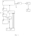
- the device according to FIG. 1 comprises an isolating amplifier 1, to which an electrode 2 and at least one sensor 3 for the detection of physiological measuring signals are connected.
- an electrode 2 for example, an epicortical electrode or brain electrode can be used.
- the isolation amplifier is further connected to a signal processing and control unit 4 connected to an optical transmitter 5 for stimulation is.
- the optical transmitter 5 is connected via optical waveguide 6 to an optical receiver 7, which communicates with a stimulator unit 8 for generating signals.
- the signal generation stimulator 8 is connected to an electrode 2.
- a relay 9 or transistor At the entrance of the electrode 2 in the buffer amplifier 1 is a relay 9 or transistor.
- the unit 4 is connected via a line 10 to a telemetry transmitter 11, which communicates with a telemetry receiver 12, which is located outside the device to be implanted and to which a means for visualization, processing and storage of the data 13 is connected.
- a telemetry transmitter 11 which communicates with a telemetry receiver 12 which is located outside the device to be implanted and to which a means for visualization, processing and storage of the data 13 is connected.
- a telemetry transmitter 11 which communicates with a telemetry receiver 12, which is located outside the device to be implanted and to which a means for visualization, processing and storage of the data 13 is connected.
- a telemetry transmitter 11 which communicates with a telemetry receiver 12 which is located outside the device to be implanted and to which a means for visualization, processing and storage of the data 13 is connected.
- a telemetry transmitter 11 which communicates with a telemetry receiver 12 which is located outside the device to be implanted and to which a means for visualization, processing and storage of the
- the electrode 2 may be any electrode known to those skilled in the art and suitable for the application of the invention. In the broader sense of the invention, therefore, an electrode is an article which can apply the stimuli according to the invention.
- the electrode 2 is, for example, at least two wires, at the ends of which a potential difference is applied for the purpose of stimulation. It may be a macro or microelectrode. Alternatively, the electrode 2 may also be a single wire. In this case, for the purpose of stimulation, a potential difference is applied between a single wire and the metallic part of the housing of the generator. In addition, but not necessarily, a potential difference can be measured via the electrode 2 in order to register a neuronal activity. In a further embodiment, the electrode 2 may also consist of more than two individual wires, which can be used both for the determination of a measurement signal in the brain, as well as for the stimulation.
- the electrode 2 comprises more than two wires
- at least one of these wires can also function as a sensor 3, so that in this case there is an embodiment in which the electrode 2 and the sensor 3 are combined in a single component.
- the wires of the electrode 2 may have different lengths so that they can penetrate into different brain depths. If the electrode 2 consists of n wires, where n is an integer greater than 2, then stimulation can take place via at least one pair of wires, with each sub-combination of wires being possible during pair formation. There may also be a stimulation between one of the n wires and the metallic part of the housing of the generator. In addition to this component also structurally unified sensors 3 can not be present in addition to the electrode 2.
- the neural activity is measured by the device according to the invention in a first step by means of the sensors.
- the stimulation signal is generated by further processing of the measured signal, for example by a time delay and possibly by filtering and / or amplifying the neural activity.
- the stimulation stimulus generated from this stimulation signal is then used in a third step for stimulation.
- decoupling and / or desynchronization of the pathological activity occurs in the stimulated tissue. Details of the operation of the device according to the invention are explained in Section 1.
- the device according to the invention can be realized in various embodiments of the timing of the stimulus application.
- the variants of the timing of the stimulus application are permanent, recurrent and demand-controlled stimulus application.
- the permanent stimulus application according to the invention is a simple embodiment of the device according to the invention which operates without additional demand control and permanently applies stimuli as described in section 6.1.
- the permanent stimulus application is an easy to implement embodiment of the device according to the invention.
- due to the self-regulating demand control according to the invention described in Section 5, a good decoupling and / or desynchronizing effect of permanent stimulation with low energy input into the population to be decoupled or into the population to be desynchronized due to the self-regulating demand control according to the invention described in Section 5, a good decoupling and / or desynchronizing effect of permanent stimulation with low energy input into the population to be decoupled or into the population to be desynchronized ,
- the device according to the invention has a controller which is programmed such that it applies an application of the stimulation stimulus to the electrode 2 only during certain time intervals. Outside these time intervals, no stimulation occurs.
- the control unit 4 is therefore programmed so that in the embodiment of the recurrent stimulation described in section 6.2 at, for example, periodically successive time points determined by a control unit, a stimulation signal is generated with a duration calculated by the control unit 4 and delivered to the electrode 2.
- a stimulation signal is generated with a duration calculated by the control unit 4 and delivered to the electrode 2.
- the stimulation signal according to Section 5 also in the recurrent stimulus application instead.
- the device according to the invention has an additional demand control as described in section 6.3.
- the device according to the invention is preferably equipped with means for detecting the occurrence and / or the expression of the pathological features in the signals of the electrode 2 and / or in the sensors 3 and / or in the processed neuronal activity.
- a stimulus signal is emitted to the electrode 2, so that stimulation of the brain tissue takes place.
- the pathological neuronal activity in the neuron populations is decoupled and / or desynchronized and thus brought closer to the natural, physiological state.
- the pathological activity differs from the healthy activity by a characteristic change of its pattern and / or its amplitude and / or its frequency content and / or in its time course.
- the means for detecting the pathological pattern are a computer which processes the measured signals of the electrode 2 and / or the sensor 3 and compares them with data stored in the computer.
- the computer has a data carrier which stores data. These may be used in the context of calibration and / or control in accordance with Sections 6 and 7.
- the control unit 4 may include, for example, a chip or other electronic device with comparable computing power.
- the control unit 4 is programmed so that in the embodiment of the demand-controlled stimulus application described in section 6.3, a stimulation stimulus is generated in a stimulation interval predetermined by the control unit 4 and delivered to the electrode 2.
- a stimulation stimulus is generated in a stimulation interval predetermined by the control unit 4 and delivered to the electrode 2.
- the control unit 4 controls the electrode 2, preferably in the following manner:
- the control data are forwarded by the control unit 4 to an optical transmitter for the stimulation 5, which activates the optical receiver 7 via the light guide 6.
- an optical transmitter for the stimulation 5 which activates the optical receiver 7 via the light guide 6.
- a galvanic separation of the control unit 4 from the electrode 2 is effected. This means that interference of noise signals from the signal processing and control unit 4 into the electrode 2 is prevented.
- an optical receiver 7 is for example a photocell into consideration.
- the optical receiver 7 transmits the signals input via the optical transmitter for the stimulation 5 to the stimulator unit 8.
- Targeted stimuli are then transmitted via the electrode 2 to the target area in the brain via the stimulator unit 8.
- a relay 9 In the event that is also measured via the electrode 2, starting from the optical transmitter for the stimulation 5 via the optical receiver 7 and a relay 9 is driven, whereby the interference of interference signals is prevented.
- the relay 9 or the transistor Ensures that neuronal activity can be re-measured immediately after each stimulus without overdriving the isolation amplifier.
- the galvanic isolation does not necessarily have to be done by an optical coupling of the control signals, but also other alternative controls can be used. These may be, for example, acoustic connections, for example in the ultrasonic range. A trouble-free control can also be realized, for example, with the aid of suitable analog or digital filters.
- the device according to the invention preferably communicates with means for visualization and processing of the measurement and / or stimulation signals and for data backup 13 via the telemetry receiver 12.
- the unit 13 may have the data analysis methods mentioned below.
- the device according to the invention can be connected via the telemetry receiver 13 with an additional reference database in order, for example, to monitor the proper operation of the device and, if necessary, design the control mechanisms described in Section 7.2 more efficiently by modifying the parameters.
- Section 1 details the mechanism of stimulation. Definitions of the most important terms can be found in Section 2. The work steps from the measurement of the neural activity to its processing up to the generation of the stimulation signal are explained in section 3. The spatial arrangement of the electrode and sensors is the subject of Section 4. Section 5 addresses the self-regulatory demand control of the stimulation signals. The control of the stimulus application and the Calibration and adjustment of pacing parameters are described in Sections 6 and 7. Section 8 explains examples and other uses and embodiments of the device. The advantages of the device according to the invention are given in Section 9.
- the driven neuron population can be decoupled from the driving neuron population.
- the driving neuron poling can also be desynchronized. This relationship is in FIG. 4 shown.
- the desired state that is the complete decoupling and / or desynchronization, arises typically, during fewer periods of neuronal activity, often in less than one period.
- there is a need for permanent or recurrent stimulation since experience shows that the nerve cell population to be decoupled and / or the nerve cell population to be desynchronized resynchronizes after disconnection of the stimulation due to illness and / or due to the coupling.
- the stimulation according to the invention is directly related to the neuronal activity, the amplitude of the resulting stimulation influence, ie the sum of the coupling and stimulation, is automatically minimized to the neuron population to be decoupled or to be desynchronized after successful decoupling and / or desynchronization.
- the feedback stimulation signal ie the processed neuronal activity, ie the extent of the synchronization and thus the coupling permanently controls the strength and shape of the stimulation signal.
- the applied stimulation signal compensates for the force of the external coupling and / or the internal synchronization so that the amplitude of the resulting stimulation influence on the neuron population to be decoupled or on the desynchronized neuron population is minimized and its neuronal activity comes closer to the natural, physiological state.
- This process works for a wide range of modifiable pacing parameters, such as pacing period T, time delay, and intensity, does not require extensive calibration, and has a high Fault Tolerance.
- the energy input into the tissue to be decoupled or into the tissue to be desynchronized is minimized due to the direct relationship between neuronal activity and stimulation patterns, which leads to fewer side effects.
- the device according to the invention and the controller are equipped with means that can perform all steps of the treatment method according to the invention. Therefore, with the disclosed method steps, means for carrying out the method step should also be disclosed implicitly.
- the process steps thus also represent the functionalized device features simultaneously.
- an electrode is introduced into a brain area or - in the case of an epicortical electrode - attached to a brain area.
- this region of the brain is selected to be directly or indirectly associated with one or more regions of the brain or directly to one of those regions responsible for the formation of the disease or driven by the pathological activity.
- the electrode emits an electrical signal in its surroundings, which causes decoupling and / or desynchronization either directly in its surroundings or via a nerve fiber bundle in another area.
- the measured and processed, preferably temporally delayed, neural activity see Section 3 is used as a stimulation signal.
- the device according to the invention therefore has a control which activates the electrode 2 in such a way that it effects a decoupling and / or a desynchronization in its near environment and / or by forwarding the stimulation via a fiber bundle in another brain area.
- the electrode is stimulated with stimuli which are formed from the measured and processed neural activity with preferably a time delay of an integer multiple of T / 2 .
- T is the stimulation period and, as described below, substantially approximates the period of the rhythmic neural activity of the driving or driven neuron population. If the stimulating electrode 2 is not located in the area to be decoupled and in the area to be desynchronized, when driving such an electrode 2, the transit time between the stimulus site and the location of the neuron population influenced thereby must be considered. This is described in Section 7.3. Surprisingly, this stimulation leads to a decoupling and desynchronization of the entire neuron population to be decoupled and / or to a desynchronization of the neuron population to be desynchronized, which is accompanied by a suppression of the pathological symptoms. If the electrode 2 is located outside the area to be decoupled and desynchronized, effects of indirect stimulation as described in section 7.3 must be considered.
- the goal of suppressing the pathological symptoms is achieved in a qualitatively different way from the above-mentioned prior art.
- the morbidly synchronous, driving nerve cell network is simply desynchronized or another neuron population driven by the pathological activity is decoupled from this force and desynchronized, resulting in suppression of the pathological symptoms leads.
- the physiological activities of the individual neurons are not affected.
- the neuronal activity processed according to Section 3.3 is used at the stimulus site. The surprisingly occurring decoupling and / or desynchronization is supported by the interaction between the neurons in the driven area.
- a mechanism of action which is responsible for the morbid synchronization.
- the best results are achieved when using the stimulation stimuli generated from the stimulation signals whose time delays correspond to integer multiples of the half stimulation period T.
- the stimulation period T approximates the period of the pathological activity.
- treatment successes are also achieved if the time delays of the stimuli emitted via the electrode 2 contain other time delays. In such a case, for example, at least a partial decoupling and / or desynchronization is brought about.
- the treatment results become better the more the selected time delays are close to multiples of the half-period of the pathological activity.
- the description of the mechanism of the device according to the invention is essentially based on the concept of neuronal activity.
- the neural activity of the neuron population to be decoupled and / or desynchronized (see terms of the driving and driven populations) is measured, stored and processed according to Section 3.3 and used as a feedback stimulation signal, whereby the self-regulating demand control according to the invention is realized.
- the measured neuronal activity of the neuron population to be decoupled and / or of the neuron population to be desynchronized is understood to mean a signal which represents the temporal development of the activity of the neuron population to be decoupled and / or desynchronized.
- local field potentials may reflect the temporal evolution of the activity of the neuron population to be decoupled and / or desynchronized.
- the neuronal activity can preferably be measured directly in the area to be decoupled and / or in the area to be desynchronized, but it can also be an activity of, for example, another area of the brain, for example the motor cortex and associated with the neural activity of the area to be decoupled and / or desynchronized or the premotor cortex, or the activity of a muscle group controlled by the area to be decoupled and / or desynchronized.
- neuronal activities can be measured and combined at different locations in order to obtain a sufficient representation of the neuronal activity of the neuron population to be decoupled and / or of the neuron population to be desynchronized.
- These variables associated with the neural activity of the area to be decoupled and / or the area to be desynchronized are also referred to below as neural activity and are encompassed by this term.
- a rhythm is understood to mean the rhythmic, ie approximately periodic, neuronal activity that can result from a pathologically exaggerated synchronous activity of nerve cells.
- a rhythm can be short-term or long-lasting.
- a central term for the device according to the invention is the period of the rhythmic neural activity, which serves as a temporal reference for the application of stimulation stimuli.
- the stimulation period T By adapting the stimulation period T, as described for example in section 7.2.1, it is preferably effected that the period of the rhythmic neuronal activity coincides with the stimulation period T.
- the driving population is understood to be the nerve cell population which generates the pathologically synchronous neuronal activity or reproduces the pathologically synchronous activity of a subordinate area.
- the driving population may pass the pathologically synchronous activity to the driven population ( Figure 4 ).
- the morbid rhythm of the driving neuron population will cause (1) involvement of substantially all of the driving neuron population and / or (2) in part of the driving neuron population and / or (3) in a third neuron population different from the driving and driven neuron populations which drives the driving neuron population.
- the connection of the subthalamic nucleus - globus pallidus exterior which function as a pacemaker by disease, and a pathologically rhythmic one may serve generate synchronous activity.
- the generated synchronous activity controls the neuronal activity of the cerebral area, e.g.
- the motor cortex which can be referred to here as a driven population and is further associated with muscles and controls their activity.
- a stimulation is understood that minimizes the morbid driving effect of the driving neuron population on the driven neuron population so much that it functionally - that is, for the expression of symptoms - no longer plays a role.
- the target population is understood to be the nerve cell population stimulated directly by an implanted stimulation electrode.
- a target population is directly stimulated by an electrode implanted in or near it.
- the populations to be decoupled and / or desynchronized are stimulated either directly or indirectly.
- the stimulation electrode 2 is located directly in the area to be decoupled or in the area to be desynchronized. This electrode 2 influences the target population, which is located in the area to be decoupled or in the area to be desynchronized.
- the area to be decoupled or desynchronized by the stimulation electrode 2 not directly stimulated. Rather, a target population or a fiber bundle, which are functionally closely connected to the area to be decoupled or to be desynchronized, is stimulated via the electrode 2.
- the stimulation effect on the area to be decoupled or the area to be desynchronized is preferably forwarded via anatomical connections.
- target area should be introduced as a generic term for target population and fiber bundles. The term target area should be understood below to mean the neuron population functionally closely connected to the area to be decoupled or to be desynchronized and the connecting fiber bundle, which are stimulated directly by the implanted electrode 2.
- This temporal shift is referred to as the time delay below and represents an important pacing parameter associated with the stimulation period T corresponding to the period of rhythmic neuronal activity.
- the feedback stimulation signal or stimulation signal is the signal that represents the measured and processed neural activity and serves as the basis for the stimulation stimuli.
- the processing steps can be carried out, for example, as described in Section 3.3.
- the stimulation signal is from the edited neural activity composed and used to stimulate the decoupled or desynchronizing brain area.
- To form the feedback stimulation signal it may be necessary to generate measurement signals by multiple, possibly independent processing steps with different processing parameters (in particular different time delays), which then adds and / or multiplies and / or divides and / or to form the actual stimulation signal subtracted and / or calculated by other non-linear functions. From the feedback stimulation signals stimulation stimuli are generated and then applied by means of the electrode to the target population.
- the driven neuron population is decoupled from the driving neuron population by means of direct or indirect stimulation.
- the resulting stimulus effect on the population to be decoupled is the sum of the stimulation signal and the driving force of the coupling with the driving population.
- the driving population to be desynchronized is desynchronized by means of the stimulation.
- the resulting stimulation effect on the population to be desynchronized only the stimulation signal Due to the self-regulating demand control described in Section 5, the amplitude of the resulting stimulation effect on the neuron population to be decoupled or desynchronized after self-isolation and / or desynchronization is automatically minimized.
- a pathologically synchronous neuron population in one area of the brain can act as a driving force on another downstream neuron population through rhythmic activity. This may result in an intermodulation scheme between the populations in the form of "driving population - driven population", as in Figure 4 is shown schematically. If the driving force is strong enough, the driven neuron population is also synchronized, which can cause the pathological symptoms. This occurs when the driven population drives the muscles, as is the case with the premotor cortex or motor cortex.
- the device according to the invention and the stimulation methods according to the invention to desynchronize the pathologically synchronous neuronal activity, which makes the suppression of the symptoms possible.
- the driven neuron population 2 is decoupled from the driving population 1 and desynchronized, or, in desynchronizing stimulation mode, the driving neuron population 1 is desynchronized.
- the driven neuron population 2 is stimulated directly or indirectly in accordance with sections 3.4 and 4.1 by means of a stimulation electrode.
- the stimulation causes a decoupling of the neuron population 2 from the driving neuron population 1, resulting in a desynchronization of the population 2.
- the driving neuron population 1 is stimulated directly or indirectly by means of a stimulation electrode.
- population 1 is desynchronized so that its driving force on population 2 is eliminated.
- the latter is then also desynchronized, thereby suppressing the pathological symptoms. If population 2 self-synchronizes, it must be directly desynchronized like a driving neuron population.
- the resulting stimulation effect on the driven neuron population is the sum of the stimulation signal and the driving force of the driving population.
- the resulting stimulation effect on the driving neuron population is solely the influence of the stimulation signal.
- the time profile of the neural activity of the area to be decoupled and / or the driving area can be measured directly and / or indirectly via the sensors 3.
- the temporal course of the activity of a muscle group influenced by the area to be decoupled and / or the driving area and / or the time course of the activity of a neuron population assigned to the area to be decoupled and / or driven are measured via at least one of the sensors 3.
- the sensors 3 are in the brain and / or outside the brain. In the brain, they are positioned in the area to be decoupled and / or in the driving area and / or in at least one other, functionally related area. Outside the brain, the sensors 3 are located on parts of the body which are in connection with the morbidly synchronized neuronal activity, for example as electrodes on a trembling muscle.
- the measured signals of the neuronal activity of the neuron populations for example the muscular activity (which is also referred to as neuronal activity, see Section 2), are processed and stored in a signal processing unit 4.
- the measurement, processing and storage can be done permanently or at discrete intervals. In the latter case, the duration and / or the distances of the discrete measurement intervals are determined by a deterministic and / or stochastic algorithm.
- the processed neural activity i. the feedback stimulation signal is determined by the application of at least one component of the above processing steps.
- the stimulation signals can be generated from the measured neural activity with always the same processing steps. It is also possible to temporally vary the set of treatment steps and / or their parameters by a deterministic and / or stochastic and / or combined stochastic / deterministic algorithm.
- a stimulation stimulus is understood to mean a stimulus which is applied via the electrode 2 and acts in a time interval.
- the feedback stimulation signals that is, the neuronal activity processed according to section 3.3, are used.
- the stimulation signals are multiplied, divided, added and / or subtracted from each other and / or with themselves and / or transformed by means of other nonlinear functions.
- the time delays used in the processing of the neural activity are given, for example, as fractions of the period of the oscillatory, decoupling and / or driving neural activity and are preferably substantially a multiple of one N of the period where N is a small integer, for example 2 . is.
- the time delays of the stimulation signals can also be selected to be greater than the stimulation period T, for example.
- the device according to the invention also offers the possibility of drawing several, preferably different, time delays in order to form the stimulation stimulus.
- the resulting delayed feedback stimulation signals may be combined linearly and / or nonlinearly into a stimulation stimulus.
- the device according to the invention has means which apply the described electrical stimulation stimulus in the manner described.
- the means are the electrode 2, a controller 4, which outputs control signals to the electrode 2 for the delivery of these stimuli.
- sensors 3 and the signal processing unit 4 which receives the neural activity and prepares for further use as a stimulation stimulus.
- a stimulation stimulus is generated whose net charge entry is essentially zero.
- the electrode 2 can be driven with the same stimulation stimulus, in the form of the same processed neuronal activity according to Section 3.3. It is also possible to trigger the electrode 2 with different stimulation signals and / or combinations of the stimulation signals and / or by means of different transformations and / or combinations of the stimulation signals.
- the order and / or the type and / or the energy input and / or the parameters of the stimuli can be determined with a deterministic and / or stochastic and / or combined stochastic / deterministic algorithm.
- the time delays and / or polarity used in the processing steps can be used and / or application duration and / or intensity of the stimulation stimulus systematically or randomly controlled, that is, according to a deterministic or stochastic rule, be varied.
- the device according to the invention has a controller which is programmed so that it controls the time delays and / or the polarity and / or the application duration and / or the intensity of the processing steps of the stimulation stimulus deterministically and / or stochastically.
- An electrode 2 is preferably used for stimulation.
- the electrode 2 In the case where the electrode 2 is positioned in the nerve cell population to be decoupled, the electrode should preferably be arranged so that the whole of the nerve cell population to be decoupled can be stimulated with the electrode. This can be realized with geometric positioning of the electrode. For example, the electrode 2 can be positioned in the center of the area to be decoupled.
- the indirect stimulation can be effected by stimulation of a neuron population different from the nerve cell population to be decoupled and / or by stimulation of a fiber bundle connected to the nerve cell population to be decoupled.
- the mechanism of the device according to the invention is that, as described in Sections 1 and 3, the measured and processed neuronal activities of the neuron population to be decoupled and / or the driving neuron population are applied again as a stimulation.
- the sensors 3 are one of the most important components of the device according to the invention and, as described in section 3.2, can be positioned either outside the neuron population to be decoupled and the driving neuron population or preferably directly in the neuron population to be decoupled and / or driven. Preferably, only one sensor 3 is used to detect the activity of the neuron population to be decoupled and / or driven.
- the number of sensors to be implanted is kept as low as possible in order to prevent unnecessary tissue damage and, above all, cerebral haemorrhage during implantation.
- the sensors 3 should preferably be arranged so that a large part of the nerve cell population to be decoupled and / or the driving nerve cell population can be detected with the sensors ,
- This can be realized with geometric arrangement of the sensors with regard to the to be decoupled and / or the driving tissue. In the case of an arrangement with only one sensor 3, this can for example be located in the center of the tissue.
- the sensors may be arranged in a symmetrical manner.
- the indirect measurement can be carried out by measuring the activity of a neuron population different from the neuron population to be decoupled and / or a fiber bundle and / or a body part which is connected to the nerve cell population to be decoupled is.
- One of the most important features of the mechanism of the device according to the invention is a self-regulating demand control of the stimulation signal.
- the self-regulation described occurs in that the stimulation stimuli consist of the processed neuronal activity.
- a large variance of the measured neuronal activity is to be expected. This leads directly to an inventive time-delayed, stimulation with an increased stimulation amplitude.
- the force of the applied stimulation signal compensates for the force of the internal synchronization and / or the coupling with the driving population of the area to be decoupled, so that a decoupling and desynchronization of the population to be decoupled results.
- the amplitude of the resulting stimulation effect on the population to be decoupled ie the sum of stimulation and coupling, is minimized independently.
- a low-variance neuronal activity is expected, directly influencing and independently adapting the stimulation signals.
- the device of the present invention automatically accommodates the increased need for decoupling and / or desynchronizing stimulation by allowing the greater variance in neural activity to form a stronger stimulus stimulus leads. This represents a self-regulating demand control of the device according to the invention.
- the mechanism underlying the self-regulating demand control acts in all embodiments of the device according to the invention which are described in more detail below.
- the temporal control of the stimulus application is understood to be a preferably pre-programmed embodiment of the device according to the invention, the stimulation stimulus being applied in a specific manner by means of the stimulator unit 8.
- the variants of the timing of the stimulus application are permanent, recurrent and demand-controlled stimulus application. Additionally, manual demand control may be implemented, for example, for a stimulus application performed by the patient or physician.
- the device according to the invention has a controller which is programmed in such a way that it carries out a continuous application of the stimulation stimulus to the electrode 2.
- the permanent stimulus application represents the simplest and easy-to-implement embodiment of the device according to the invention.
- the device according to the invention has a controller which is programmed such that it applies an application of the stimulation stimulus to the electrode 2 only during certain time intervals. Outside these time intervals, no stimulation occurs.
- the stimulation stimulus can be administered periodically strictly periodically or not periodically.
- the device of the invention has a controller programmed to periodically and / or non-periodically control the intervals between stimulation intervals and / or the duration of the intervals.
- a non-periodic sequence of stimulation stimuli can be generated by a stochastic and / or deterministic and / or combined stochastic / deterministic algorithm to achieve the desired decoupled and desynchronized state of the population to be decoupled.
- a combination of deterministic and stochastic regularities is understood to mean a functional relationship in which deterministic and stochastic terms are functionally, eg. B. are connected to each other by addition and / or multiplication.
- the stimulation and measurement intervals can be arranged overlapping or at the same time or separated in time.
- an adjustment of the intensity parameters can take place according to section 7.2.3. Also, an adjustment of the time parameters - stimulation period T and / or time delays - during the recurrent stimulation according to sections 7.2.1 and 7.2.2 in combination with an adjustment of the stimulation intensity or independently of it.
- the device has a controller which is programmed so that it makes the switching on and off of the stimulation stimulus corresponding to the specific states of the neuron population to be decoupled and / or the driving.
- the control unit 4 uses the measurement signals and / or the stimulation signals for the detection of a pathological feature. The activation of the stimulation takes place, for example, as described below.
- the stimulation period T is adjusted as described in Section 7.2.1 to the instantaneous frequency of the neuron population to be decoupled and / or to be driven. It then becomes present in the presence of the pathological feature Stimulus applied to the instantaneous frequency adapted stimulation period T applied.
- the time delays according to Section 7.2.2 can be adjusted and / or the intensity of this stimulus preferably remains constant.
- the intensity parameters can also be modified as described in Section 7.2.3 according to the stimulation effect.
- the distance from sensor 3 to the area to be decoupled and / or the driving area in which the neural activity to be measured is generated causes a change in the amplitude in the disease-specific frequency range.
- a certain expression of the disease-specific feature ie the expression of the rhythmic activity in the disease-specific frequency range, is not uniquely associated with the disease-specific symptoms. Since the disease-specific rhythm has effects on complex neural networks in the brain, which typically also do not obey simple linear dynamic laws, there are no one-to-one relations between disease-specific rhythm and severity of symptoms.
- the tremor caused by the disease-specific rhythm is significantly less than if the disease-specific rhythm is in resonance with the biomechanically predetermined natural frequency of the limb.
- the characteristic features, such as the dominant frequency and the amplitude, of the measured neural Activity are in a field of expertise known to those skilled in the art.
- the value of the severity of the disease-specific feature of the neuronal activity measured via sensor 3 is referred to as the threshold above which the occurrence of symptoms, for example of the tremor, typically occurs.
- the threshold is a parameter to be selected for the embodiment of the on-demand stimulus application described in Section 6.3.
- the device according to the invention therefore comprises in the form of the control unit 4 means for detecting a threshold value.
- the advantage is achieved that the effectiveness of the device according to the invention does not depend critically on the choice of the threshold, but with respect to the choice of threshold a large error tolerance is given, for example in a range of up to 50% of maximum expression of the disease-specific feature.
- the choice of threshold is made either intraoperatively or preferably in the first days after surgery by measuring neuronal activity via sensor 3, determining the severity of the disease specific feature and comparing it with the severity of the symptoms, e.g. As the strength of the tremor determined.
- the threshold is taken to be a representative value, for example the mean, of a collective of patient thresholds.
- the choice of threshold is checked at substantially regular intervals, for example as part of bi-annual controls.
- the three stimulation methods described above may preferably be used in different combinations with the pacing parameter adjustment methods described in Section 7.2.
- Common to all three stimulation methods is the inherent self-regulating demand control of the invention.
- the direct dependence of the stimulation signals on the measured neuronal activity requires a self-regulatory demand control described in Section 5, thereby minimizing the energy input into the population to be decoupled.
- This self-regulating Demand Control is independent of the realization of the additional Demand Control described in Section 6.3 and the calibration and control of the parameters as described in Section 7.
- the electrode 2 lies in the neuron population to be decoupled.
- the case where the electrode is outside the neuron population to be decoupled is considered separately at the end of the section.
- a calibration and adaptation can be carried out: the frequency of the stimulation signals whose reciprocal corresponds to the stimulation period, the time delays of the stimulation signals and the intensity of the stimulation stimulus.
- the frequency range of the pathological neuronal activity is known to the person skilled in the art for the respective clinical pictures ( Elble RJ and Koller WC (1990): Tremor, John Hopkins University Press, Baltimore ). From this frequency range, the average value can preferably be taken. Alternatively, the value of the frequency to be expected in terms of age and gender can instead be used from a database.
- the initially predetermined frequency coincides with the actually existing frequency of the activity of the neuron population to be decoupled or the activity of the driving neuron population.
- the regulation of the stimulation period T described under 7.2.1 also works if an initial value strongly deviating from the correct frequency value is used.
- strongly deviating means that the value can also be too large or too small by at least a factor of 10.
- the value of the frequency at the beginning of the stimulation can also preferably be obtained by an individual adaptation to the respective patient. This can be realized, for example, by measuring the neuronal activity preparatory to stimulation and estimating the dominant frequency of the activity of the neuron population to be decoupled and / or driven, as described in Section 6.3.
- the starting value for the frequency is the mean value of the frequency selected during the previous operation of the device.
- the stimulation period T is calculated as the reciprocal of the start value of the frequency.
- the time delays of the stimulation signals are preferably determined after a first determination of the stimulation frequency or the stimulation period T.
- the time delays are selected as fractions of the stimulation period T, eg T / 2.
- the adjustment of the time delays described in section 7.2.2 also works in the case described above, in which at least some of the time delays of the feedback stimulation signals from which the stimulation stimuli are generated are different and / or exceed the stimulation period T.
- the output values of the stimulation parameters which determine the intensity of the stimulation stimulus are determined according to empirical values known to the person skilled in the art (eg maximum amplitude 10 V).
- the intensity control described under 7.2.3 also works if an initial value deviating significantly from the most favorable intensity value is used. Here strongly deviating means that the Value too large by at least a factor of 10 (preferably maximum amplitude 10 V) or may be too small. Alternatively, it is therefore also possible to begin with an intensity value which is within the range known to the person skilled in the art. In particular, it is preferable to start stimulation with small values of intensity, for example maximum amplitude of 0.5 V, of the stimulation signal, thus possibly reducing the side effects of the stimulation. If there is a need to use a stronger pacing signal, increase the intensity in small increments as described in Section 7.2.3.
- the initial values for frequency and intensity can be specified and must be determined, in particular not in the context of a time-consuming calibration.
- the neural activity is measured, which is used as a stimulation signal after processing.
- a stimulation signal for example, in Parkinson's disease in addition to a measurement via the sensors 3 directly in the area to be decoupled and / or in the driving area also a measurement of activity in a downstream area, z. B. the premotor cortex via epicortical sensors.
- the dominant mean period is determined. Different algorithms can be used for this purpose.
- the stimulation period T can be adapted to the instantaneous period of the neuron population to be decoupled and / or driven.
- the instantaneous period are determined as the time difference of two subsequent maxima of the measured neural activity.
- the mean frequency of the neural activity may first be estimated, and the stimulation period T may be set as the inverse of the mean frequency. If not only disease specific activity is measured via sensor 3, for this type of frequency estimation, first the disease specific activity must be extracted via bandpass filtering of the disease specific frequency range.
- the frequency can be determined via the frequency estimators mentioned in Section 6.3.
- the time window used for this frequency estimation has a length which may be open according to upper values and, for example, corresponds to 10000 periods, preferably 1000 periods, particularly preferably 100 periods of the pathological activity, but also to any other values.
- the time delays of the stimulation signals are preferably selected as fractions of the stimulation period T.
- the time delays may be fixed or, preferably, adjusted to the pacing period adjusted according to section 7.2.1.
- the time delays of the stimulation signals are preferably varied during the stimulation by a deterministic or stochastic and / or combined stochastic / deterministic algorithm.
- the device according to the invention comprises means in the form of the control unit 4, which allow to vary the time delays of the stimulation signals during the stimulation.
- the time delays can be varied not only within a stimulation period but also within a plurality of periods.
- the stimulation signal corresponds to the neuronal activity, which was measured at an earlier point in time some years earlier.
- the device according to the invention has a control which detects a change in the neuronal activity and, in the absence of the change in the neuronal activity, adapts the stimulating signals to upper values. After approximately 20 successful periods of pacing, the device may begin to control the maximum strength of the stimulus slowly (eg, in increments of 0.5V per 50 cycles) as long as pacing success is still present. The stimulation success is determined as described above.
- the controller is programmed to recognize the change in neural activity and, thus, the pace of stimulation.
- the maximum stimulus intensity on a time scale between 10 and 1000 periods of neuronal activity is controlled so that the decoupled neuron population is sufficiently decoupled and desynchronized. Irrespective of the value of the stimulation intensity defined above, the amplitude of the resulting stimulation influence on the neuron population to be decoupled is automatically minimized following successful decoupling as a result of the properties of the stimulation mechanism of the device according to the invention described in Section 5.
- the neuron population to be decoupled is influenced via an indirect stimulation, as described in section 4.1. Since, in the case of an indirect stimulation, the conduction times between the stimulated target population on the one hand and the population to be decoupled on the other hand can be different in each case, the respective conduction times are first measured before the decoupling stimulation is carried out. For this purpose, stimulation is stimulated via the stimulation electrode 2 and the stimulus response is measured via the sensors 3 placed in the neuron population to be decoupled. This is done L times, where L is typically a small integer up to, for example, 200. From this, the average conduction time is preferably estimated in the following manner:
- the duration between the beginning of the stimulus application via the electrode 2 and the first maximum of the stimulus response or the amount of the stimulus response, ⁇ (k) is determined for each individual stimulus application.
- L is the number of stimuli applied via the stimulation electrode 2.
- a stimulus is applied via the stimulation electrode 2 with a time delay t
- the stimulus with a time delay t is generated via the stimulation electrode 2 during indirect stimulation.
- the effect of stimulation on the population to be decoupled is shown in a reduction in the amplitude of the measured neuronal activity, see FIG. 2a and 3a , showing the firing pattern of the neurons, see FIG. 2b and 3b , clearly different from the fire pattern in the pathological state.
- This stimulation influence is also reflected in the degree of synchronization of the neuron population to be decoupled, see Figure 2c and 3c again, which is a confirmation of the onset of desynchronization of the population to be decoupled.
- a self-regulating demand control described in Section 5 requires a minimization of the energy input into the population to be decoupled.
- it is possible to adapt the only important stimulation parameters, the stimulation period T and thus the time delays by measuring the frequency of the nerve cell population in the neuron population to be decoupled and / or the driving neuron population or another, closely related nerve cell population.
- the device according to the invention can also be used for desynchronization of a pathologically synchronous neuron population.
- a pathologically synchronous neuron population e.g. the driving, to be desynchronized neuron population, desynchronized by stimulation with the feedback stimulation signal according to the invention.
- the above-described properties of the device and the stimulation methods for the decoupling of the neuron population to be decoupled also apply to this embodiment of the device with the modification that the stimulation is applied in the neuron population to be desynchronized.
- a desynchronization is desired, this can be achieved with an arrangement of the stimulation electrode 2 in accordance with section 4.1. Also, a direct and indirect arrangement of the sensors 3 is possible. In this case, the sensors 3 are to be arranged so that a detection of the neuronal activity of the area to be desynchronized is possible. The details of this arrangement correspond to the details described in section 4.2, where now the activity to be desynchronized is measured. The pathologically synchronous activity of the neuron population to be desynchronized is measured and processed directly and / or indirectly in accordance with Section 3. This generates a stimulation signal that serves as the basis for the stimulation stimuli.
- the generated stimulation stimuli become the one to be reconciled Area applied so that a direct or indirect stimulation of the population to be desynchronized according to Section 3 and 4.1 is carried out, and the driving population is desynchronized according to the invention, and the pathological symptoms are suppressed.
- the driving coupling to the driven neuron population is automatically decoupled due to the desynchronization of the driving population, ie, the desynchronization of the driving neuron population eliminates the pathological drive of the driven neuron population.
- the amplitude of the resulting stimulation influence on the population to be desynchronized ie in this case the amplitude of the stimulation signal (see Section 2), is independently minimized, as described in Section 5.
- the stimulation-adapted arrangement of the electrode and sensors according to Section 4 all three control methods of control of the stimulus application according to Section 6, and the calibration and adaptation of the parameters according to Section 7 can also be used for the described embodiment of the device according to the invention.
- the device may also be used to decouple a neuron population driven by a non-synchronous pathological neuron population.
- the device can be used to decouple a population that is driven by a pathological activity and in the decoupled case itself has a non-pathological synchronous activity.
- the electrode and sensors are identical to the arrangements described in Section 4.
- the detection and processing of neuronal activity is also carried out in accordance with Section 3.
- the device can be used to eliminate or suppress a coupling of a non-pathological area. This could be used eg in the study of the interaction of neuron populations.
- the detection and processing of the neural activity and the arrangement of the electrode and sensors is done in accordance with sections 3 and 4. Is, as mentioned in the introduction, a bilateral stimulation for the purpose of decoupling the pathological activity necessary, it is preferably stimulated on both sides with two individual devices or with a device designed for this purpose, the signals can pass on at least two stimulation electrodes.
- the following diseases or symptoms can be treated by decoupling suitable brain areas with the new stimulation method.
- pathological neuronal synchronization plays a role relevant to the manifestation of the disease - specific symptoms, for example: Parkinson 's disease, essential tremor, dystonia, obsessive - compulsive disorder, tremor in multiple sclerosis, tremor as a result of stroke or another, for example tumorous tissue damage, for example in the area of the thalamus and / or the basal ganglia, choreoathetosis and epilepsy, the list should not be limiting.
- the target areas listed above for the respective diseases and / or areas coupled thereto can be selected. Because in the device according to the invention either no calibration is necessary or the calibration can be carried out very quickly, there is the possibility of testing alternative target areas in the context of electrode implantation, in which the decoupling and / or desynchronizing effect of the device according to the invention can be developed even better ,
- the invention also includes a controller which controls the stated operation of the device according to the invention and the use of the device and the controller for the treatment of the diseases Parkinson's disease, essential tremor, dystonia, obsessive compulsive disorder, choreoathetosis, tremor in multiple sclerosis, tremor as a result of stroke or other, for example tumorous tissue damage, for example in the area of the thalamus and / or basal ganglia, and epilepsy ,
- the device according to the invention can be used both as an implant for the permanent therapy of the above-mentioned neurological and psychiatric disorders and for the intraoperative target point diagnosis, that is, the intraoperative finding of the optimal target point for the electrode implantation.
Description
Die Erfindung betrifft eine Vorrichtung zur Entkopplung und/oder Desynchronisation von neuronaler Hirnaktivität nach dem Oberbegriff des Anspruchs 1.The invention relates to a device for decoupling and / or desynchronization of neuronal brain activity according to the preamble of
Eine pathologisch synchrone Hirnaktivität, wie sie beispielsweise in den Basalganglien ihren Ursprung haben kann, kann als treibende Kraft eine Synchronisation auch in nachgeschalteten Arealen, wie beispielsweise dem Motorkortex bewirken. Diese sekundäre Synchronisation ist maßgeblich an der Erzeugung der pathologischen Symptome beteiligt. Die Erfindung betrifft eine Vorrichtung, die es erlaubt, die treibende, pathologische Aktivität von den nachgeschalteten Arealen zu entkoppeln, wodurch eine starke Verringerung der pathologischen Symptome bewirkt werden kann. In einer weiteren Ausführungsform kann die erfindungsgemäße Vorrichtung auch für die Desynchronisation, d. h. für die Unterdrückung einer rhythmischen, kollektiven Aktivität bzw. eines kollektiven Feuerns der Neuronen der pathologisch synchronen Nervenzellpopulationen, die als treibende Populationen bezeichnet werden, verwendet werden.A pathologically synchronous brain activity, as may originate, for example, in the basal ganglia, can cause synchronization as a driving force in downstream areas such as the motor cortex. This secondary synchronization is instrumental in the generation of pathological symptoms. The invention relates to a device which allows to decouple the driving, pathological activity of the downstream areas, whereby a strong reduction of the pathological symptoms can be effected. In a further embodiment, the device according to the invention can also be used for desynchronization, i. H. for the suppression of rhythmic, collective, or collective firing of the neurons of the pathologically synchronous nerve cell populations, referred to as driving populations.
Bei Patienten mit neurologischen oder psychiatrischen Erkrankungen, z. B. Morbus Parkinson, essentiellem Tremor, Dystonie oder Zwangserkrankungen, sind Nervenzellverbände in umschriebenen Bereichen des Gehirns, z. B. des Thalamus und der Basalganglien krankhaft aktiv, z. B. übersteigert synchron. In diesem Fall bildet eine große Anzahl von Neuronen synchrone Aktionspotentiale aus; die beteiligten Neuronen feuern übermäßig synchron. Beim Gesunden hingegen feuern die Neuronen in diesen Hirngebieten qualitativ anders, z. B. auf unkorrelierte Weise. Die pathologisch synchrone Hirnaktivität verändert die neuronale Aktivität in anderen Hirngebieten, z. B. in Arealen der Großhirnrinde wie dem primär motorischen Cortex. Dabei zwingt die pathologisch synchrone Aktivität im Bereich des Thalamus und der Basalganglien den Großhirnarealen ihren Rhythmus auf, so dass schließlich die von diesen Arealen gesteuerten Muskeln pathologische Aktivität, z. B. ein rhythmisches Zittern (Tremor), entfalten.In patients with neurological or psychiatric disorders, eg. Parkinson's disease, essential tremor, dystonia or obsessive compulsive disorder, are nerve cell aggregates in circumscribed areas of the brain, e.g. As the thalamus and basal ganglia pathologically active, z. B. Exaggerated synchronously. In this case, a large number of neurons will form synchronous action potentials; the involved neurons fire overly synchronously. In the healthy, however, fire the neurons in these brain areas qualitatively different, z. B. in an uncorrelated manner. The pathologically synchronous brain activity alters the neuronal activity in other brain areas, eg. B. in areas of the cerebral cortex as the primary motor cortex. The pathologically synchronous activity in the area of the thalamus and the basal ganglia forces the cerebral areas to become rhythmic, so that finally the muscles controlled by these areas have pathological activity, e.g. B. a rhythmic tremor (tremor) unfold.
Bei Patienten, welche medikamentös nicht (mehr) behandelt werden können, wird, je nach Krankheitsbild und je nach dem, ob die Erkrankung einseitig oder beidseitig auftritt, eine Tiefenelektrode einseitig oder beidseitig implantiert. Unter der Haut führt dabei ein Kabel vom Kopf zum sogenannten Generator, welcher ein Steuergerät mit einer Batterie umfasst, und beispielsweise im Bereich des Schlüsselbeins unter der Haut implantiert ist. Über die Tiefenelektroden wird eine Dauerreizung mit einer hochfrequenten periodischen Abfolge (pulse train mit einer Frequenz von > 100 Hz) von Einzelpulsen, z. B. Rechteckpulsen, durchgeführt. Ziel dieser Methode ist es, das Feuern der Neuronen in den Zielgebieten zu unterdrücken. Der Wirkmechanismus, welcher der Standard-Tiefenstimulation zugrunde liegt, ist noch nicht hinreichend geklärt. Die Ergebnisse mehrerer Studien sprechen dafür, dass die Standard-Tiefenstimulation wie eine reversible Läsionierung, d. h. wie eine reversible Ausschaltung des Gewebes, wirkt: Die Standard-Tiefenstimulation unterdrückt das Feuern der Neuronen in den Zielgebieten und/oder in damit verbundenen Hirnarealen.In patients who can no longer be treated with medication, a deep electrode is implanted on one or both sides, depending on the clinical picture and whether the disease is unilateral or bilateral. Under the skin, a cable leads from the head to the so-called generator, which comprises a control unit with a battery, and is implanted, for example, in the region of the collarbone under the skin. About the depth electrodes is a continuous stimulation with a high-frequency periodic sequence (pulse train with a frequency of> 100 Hz) of individual pulses, z. B. rectangular pulses performed. The aim of this method is to suppress the firing of neurons in the target areas. The mechanism of action on which the standard depth stimulation is based is not yet sufficiently clarified. The results of several studies suggest that standard deep stimulation works like a reversible lesion, ie reversible tissue rejection: Standard deep stimulation suppresses the firing of neurons in the target areas and / or brain areas.
Nachteilig bei dieser Stimulationsform ist, dass der Energieverbrauch des Generators sehr hoch ist, so dass der Generator inklusive Batterie häufig schon nach ca. ein bis drei Jahren operativ ausgetauscht werden muss. Noch nachteiliger ist, dass die Hochfrequenz-Dauerstimulation als unphysiologischer (unnatürlicher) Input im Bereich des Gehirns, z. B. des Thalamus bzw. der Basalganglien, im Laufe von wenigen Jahren zur Adaptation der betroffenen Nervenzellverbände führen kann. Um denselben Stimulationserfolg zu erzielen, muss dann infolge dieser Adaptation mit höherer Reizamplitude stimuliert werden. Je größer die Reizamplitude ist, desto größer ist die Wahrscheinlichkeit, dass es infolge der Reizung von Nachbararealen zu Nebenwirkungen - wie Dysarthrie (Sprechstörungen), Dysästhesie (zum Teil sehr schmerzhafte Missempfindungen), zerebelläre Ataxie (Unfähigkeit, ohne fremde Hilfe sicher zu stehen) oder Schizophrenie artigen Symptomen etc. - kommt. Diese Nebenwirkungen können vom Patienten nicht toleriert werden. Die Behandlung verliert daher in diesen Fällen nach wenigen Jahren ihre Wirksamkeit.The disadvantage of this form of stimulation is that the energy consumption of the generator is very high, so that the generator including the battery often has to be replaced operationally after about one to three years. Even more disadvantageous is that the high frequency continuous stimulation as unphysiologischer (unnatural) input in the brain, z. As the thalamus or the basal ganglia, in the course of a few years to adapt the affected nerve cell associations can lead. In order to achieve the same stimulation success, then must be stimulated as a result of this adaptation with higher stimulus amplitude. The greater the stimulus amplitude, the greater is the likelihood that side effects such as dysarthria (dysfunctions), dysesthesia (sometimes very painful discomfort), cerebellar ataxia (inability to remain unaided), as a result of the irritation of neighboring areas, or Schizophrenia-like symptoms etc. - comes. These side effects can not be tolerated by the patient. The treatment therefore loses its effectiveness in these cases after a few years.
Bei anderen Stimulationsmethoden, wie sie beispielsweise in
Bei den oben erwähnten Stimulationsmethoden ist die Verwendung von einer oder mehreren Tiefenelektroden notwendig, was einen hohen operativen Aufwand und ein großes Risiko von Komplikationen wie, z.B. mögliche Hirngewebsschädigungen oder eine Hirnblutung während der Implantation der Tiefelektroden, für den Patienten darstellt. Dieses Risiko sollte im Sinne einer erfolgreichen Heilung des Patienten und einer Verminderung von Nebenwirkungen aber vermindert werden.In the above-mentioned stimulation methods, the use of one or more depth electrodes is necessary, resulting in a high operative effort and a high risk of complications such as, for example, possible brain tissue damage or cerebral haemorrhage during the implantation of the deep electrodes. represents for the patient. However, this risk should be reduced in terms of a successful cure of the patient and a reduction of side effects.
Aufgabe der Erfindung ist es daher, eine Vorrichtung zur Entkopplung und/oder Desynchronisation von neuronaler Hirnaktivität zu schaffen, mit der Patienten mit krankhaft synchronisierter Hirnaktivität mild und effizient behandelt werden können. Hierbei soll eine Adaptation an einen unphysiologischen Dauerreiz unterbunden werden. Es sollen langwierige Kalibrierungsvorgänge verhindert werden und die Stimulation soll auch dann erfolgreich sein, wenn die Hauptfrequenz-Komponente der pathologisch rhythmischen Aktivität starken Schwankungen unterliegt. Des Weiteren soll die Vorrichtung eine dauerhafte Entkopplung und/oder Desynchronisation erreichen, transiente, stimulationsbedingte unphysiologische Zustände sollen weitestgehend vermieden werden. Die erfindungsgemäße Vorrichtung bedarf keiner zusätzlichen Bedarfssteuerung, die wie in Abschnitt 6.3 beschrieben, optional hinzugefügt werden kann, daher ist sie technisch leicht realisierbar und es werden nur geringe Ansprüche an die Komplexität der Steuerelektronik und damitThe object of the invention is therefore to provide a device for decoupling and / or desynchronization of neuronal brain activity, with which patients with pathologically synchronized brain activity can be treated mildly and efficiently. In this case, an adaptation to a nonphysiological persistent stimulus should be prevented. Tedious calibration procedures are to be prevented and the stimulation should be successful even if the main frequency component of the pathologically rhythmic activity is subject to strong fluctuations. Furthermore, the device should achieve a permanent decoupling and / or desynchronization, transient, stimulation-related unphysiological states should be avoided as far as possible. The device of the invention requires no additional demand control, which can be optionally added as described in Section 6.3, so it is technically easy to implement and there are only low demands on the complexity of the control electronics and thus
auch an den Stromverbrauch gestellt. Die erfindungsgemäße Stimulationsvorrichtung soll Strom sparend funktionieren, so dass die Batterien des in den Patienten implantierten Stimulators seltener operativ ausgetauscht werden müssen. Da eine Implantation nur einer Elektrode notwenig ist, und da diese Elektrode in einem nachgeschalteten und somit möglicherweise leichter zugänglichen Hirnareal implantiert wird, wie, z.B. eine Epikortikalelektrode im Bereich des Motor Cortex, stellt die erfindungsgemäße Vorrichtung eine erhebliche Verbesserung im Vergleich zu den oben erwähnten Methoden der Tiefenhirnstimulation dar. Für die Hirnstimulation ist nämlich insbesondere - in einer besonderen Ausführungsform der erfindungsgemäßen Vorrichtung - keine Tiefenelektrode notwendig, so dass keine intraoperative Blutungsgefahr durch eine Verletzung einer Arterie gegeben ist.also put on the power consumption. The stimulation device according to the invention should operate to save power, so that the batteries of the implanted in the patient stimulator must be replaced less frequently surgically. Since an implantation of only one electrode is necessary, and since this electrode is implanted in a downstream and thus possibly more easily accessible brain area, such as, e.g. an epicortical electrode in the region of the motor cortex, the device according to the invention represents a considerable improvement in comparison with the abovementioned methods of deep brain stimulation. For brain stimulation, in particular - in a particular embodiment of the device according to the invention - no deep electrode is necessary, so that there is no risk of intraoperative bleeding is given by an injury to an artery.
Ausgehend vom Oberbegriff des Anspruchs 1 wird die Aufgabe erfindungsgemäß gelöst durch die im kennzeichnenden Teil des Anspruchs 1 angegebenen Merkmale. Unter Verwendung der gemessenen und bearbeiteten Aktivität der zu entkoppelnden und/oder der zu desynchronisierenden Neuronenpopulation als Feedback-Stimulationssignal, siehe Abschnitt 3, wird die Aufgabe überraschenderweise dadurch gelöst, dass die Neuronen mit einer Elektrode durch die Stimulation mit dem Feedback-Stimulationssignal in ihrer Aktivität jeweils derart beeinflusst werden, dass es überraschenderweise zu einer vollständigen Entkopplung und/oder Desynchronisation der zu entkoppelnden Neuronenpopulation von der treibenden, pathologischen Neuronenpopulation kommt, wodurch bei einem Patienten überraschenderweise die Symptomatik unterdrückt wird. Bei einer weiteren Ausführungsform der erfindungsgemäßen Vorrichtung, wie in Abschnitt 8 beschrieben, kann die Vorrichtung beispielsweise auch zur Desynchronisation der treibenden Neuronenpopulation verwendet werden. Bei dieser Ausführungsform wird die gemessene und bearbeitete neuronale Aktivität der treibenden Neuronenpopulation als Feedback-Stimulationssignal über die Stimulationselektrode appliziert, so dass eine direkte oder indirekte Stimulation der treibenden Neuronenpopulation mit dem Feedback-Stimulationssignal erfolgt. Dadurch wird die zu desynchronisierende Neuronenpopulation so beeinflusst, dass es überraschenderweise zu einer vollständigen Desynchronisation kommt, wodurch die krankheitsbedingte Symptomatik unterdrückt wird. Hierzu umfasst die erfindungsgemäße Vorrichtung eine Steuerung 4, die das Messsignal des Sensors 3 oder der Sensoren 3 aufnimmt und aus diesem Signal ein Stimulationssignal generiert und an die Elektrode 2 als Stimulationsreiz weiter gibt.Starting from the preamble of
Die erfindungsgemäße Vorrichtung arbeitet Strom sparend, so dass im Patienten implantierte Batterien seltener ausgetauscht werden müssen.The device according to the invention works to save energy, so that batteries implanted in the patient need to be replaced less frequently.
Die erfindungsgemäße Vorrichtung ermöglicht es, den mit der entkoppelnden Stimulation intraoperativ erzielten Effekt zur Auswahl des am besten geeigneten Zielpunkts für die Elektrode zu verwenden. Bei Verwendung einer Tiefenhirnelektrode als Elektrode 2 wird während der Implantation der Elektrode im Bereich des anatomisch vorberechneten Zielpunkts in mm-Schritten vorangehend eine Testreizung und/oder Ableitung des Feedback-Signals mit der erfindungsgemäßen Vorrichtung durchgeführt. Der Zielpunkt, bei welchem sich der beste therapeutische Effekt erzielen lässt, wird als Zielpunkt für die dauerhafte Implantation gewählt.The device according to the invention makes it possible to use the effect achieved intraoperatively with the decoupling stimulation for the selection of the most suitable target point for the electrode. When using a deep brain electrode as
Neben den oben genannten Erkrankungen, die häufig anhaltende pathologisch synchrone Aktivität mit relativ konstanter Frequenz aufweisen, können auch Erkrankungen behandelt werden, bei denen es nur intermittent (kurzzeitig auftretend) zu pathologisch synchroner Aktivität kommt. Eine Hauptindikation ist dabei die Behandlung von medikamentös nicht (mehr) behandelbaren Epilepsien. Die erfindungsgemäße Vorrichtung kann beispielsweise bei den Krankheiten Morbus Parkinson, essentieller Tremor, Dystonie, Epilepsie, Depression und Zwangserkrankungen eine Unterdrückung der Symptome bewirken.In addition to the above-mentioned diseases, which often have persistent pathologically synchronous activity with a relatively constant frequency, it is also possible to treat diseases in which only intermittent (temporarily occurring) pathological synchronous activity occurs. A major indication is the treatment of medically not (more) treatable epilepsy. The device according to the invention can, for example, bring about a suppression of the symptoms in the diseases Parkinson's disease, essential tremor, dystonia, epilepsy, depression and obsessive-compulsive disorders.
Vorteilhafte Weiterbildungen der Erfindung sind in den Unteransprüchen angegeben.Advantageous developments of the invention are specified in the subclaims.
Die Figuren zeigen beispielhafte Ausführungsformen der Erfindung. Es zeigt:
-
Fig.1 : Eine erfindungsgemäße Vorrichtung -
Figur 2Beispiel 1 in Abschnitt 8.1 beschrieben wird. Zur Veranschaulichung wird inFigur 2a bis 2d die Kopplung zumZeitpunkt 4 Sekunden eingeschaltet, die Stimulation beginnt zum Zeitpunkt 7.5 Sekunden. -
Fig.2a : Zeitgang der überSensor 3 gemessenen neuronalen Aktivität der zu entkoppelnden Neuronenpopulation während des nicht gekoppelten Zustands, während der Kopplung und während der Stimulation. -
Fig.2b : Zeitgang des Feuermusters der zu entkoppelnden Neuronenpopulation während des nicht gekoppelten Zustands, während der Kopplung und während der Stimulation. -
Fig.2c : Zeitgang des Synchronisationsmaßes der zu entkoppelnden Neuronenpopulation während eines Stimulationsintervalls. Kleine Werte entsprechen geringer Synchronisation und große Werte entsprechen einer starken Synchronisation. -
Fig.2d : Zeitgang des resultierenden Stimulationseinflusses auf die zu entkoppelnde Neuronenpopulation, d.h. die Summe der Kopplungs- und Stimulationseinflüsse. -
Fig.2e : Verteilung der Feuerfrequenzen vor der Kopplung (links), während der Kopplung (Mitte) und bei eingeschalteter Stimulation (rechts). -
Figur 3er im Beispiel 2 in Abschnitt 8.1 beschrieben wird. Zur Veranschaulichung wird inFigur 3a bis 3d dieKopplung zum Zeitpunkt 4 Sekunden eingeschaltet, die Stimulation beginnt zum Zeitpunkt 7.5 Sekunden. -
Fig.3a : Zeitgang der überSensor 3 gemessenen neuronalen Aktivität der zu entkoppelnden Neuronenpopulation während des nicht gekoppelten Zustands, während der Kopplung und während der Stimulation. -
Fig.3b : Zeitgang des Feuermusters der zu entkoppelnden Neuronenpopulation während des nicht gekoppelten Zustands, während der Kopplung und während der Stimulation. -
Fig.3c : Zeitgang des Synchronisationsmaßes der zu entkoppelnden Neuronenpopulation. Kleine Werte entsprechen geringer Synchronisation und große Werte einer starken Synchronisation. -
Fig.3d : Zeitgang des resultierenden Stimulationseinflusses auf die zu entkoppelnde Neuronenpopulation, d.h. die Summe der Kopplungs- und Stimulationseinflüsse. -
Fig.3e : Verteilung der Feuerfrequenzen vor der Kopplung (links), während der Kopplung (Mitte) und bei eingeschalteter Stimulation (rechts). -
Fig.4 : Schematische Zeichnung der Kopplung zwischen der treibenden, pathologisch synchronen Neuronenpopulation 1 und der getriebenen, zu entkoppelnden Neuronenpopulation 2. Beispielsweise stellt dieNeuronenpopulation 2 den prämotorischen Kortex und/oder den Motorkortex dar.
-
Fig.1 : A device according to the invention -
FIG. 2 shows the decoupling effect of stimulation with a stimulation stimulus as described in Example 1 in Section 8.1. By way of illustration, inFIGS. 2a to 2d the pair is switched on for 4 seconds, the stimulation starts at 7.5 seconds. -
2a : Time course of the neuronal activity measured bysensor 3 of the neuron population to be decoupled during the uncoupled state, during the coupling and during the stimulation. -
2b : Time course of the fire pattern of the decoupled neuron population during the uncoupled state, during the coupling and during the stimulation. -
Figure 2c : Time course of the synchronization measure of the neuron population to be decoupled during a stimulation interval. Small values correspond to low synchronization and large values correspond to strong synchronization. -
Figure 2d : Timing of the resulting stimulation influence on the neuron population to be decoupled, ie the sum of the coupling and stimulation influences. -
Figure 2e : Distribution of the fire frequencies before the coupling (left), during the coupling (middle) and when the stimulation is switched on (right). -
FIG. 3 shows the decoupling effect of stimulation with a stimulation stimulus as described in Example 2 in Section 8.1. By way of illustration, inFigure 3a to 3d the pair is switched on for 4 seconds, the stimulation starts at 7.5 seconds. -
3a : Time course of the neuronal activity measured bysensor 3 of the neuron population to be decoupled during the uncoupled state, during the coupling and during the stimulation. -
3b : Time course of the fire pattern of the decoupled neuron population during the uncoupled state, during the coupling and during the stimulation. -
3 c : Time course of the synchronization measure of the neuron population to be decoupled. Small values correspond to low synchronization and large values to strong synchronization. -
3 d : Timing of the resulting stimulation influence on the neuron population to be decoupled, ie the sum of the coupling and stimulation influences. -
3E : Distribution of the fire frequencies before the coupling (left), during the coupling (middle) and when the stimulation is switched on (right). -
Figure 4 Schematic drawing of the coupling between the driving, pathologicallysynchronous neuron population 1 and the drivenneuron population 2 to be decoupled. For example, theneuron population 2 represents the premotor cortex and / or the motor cortex.
In den
Die Vorrichtung gemäß
Bei der Elektrode 2 kann es sich um jede Elektrode handeln, die dem Fachmann bekannt ist und die für die erfindungsgemäße Anwendung geeignet ist. Im weiteren Sinne der Erfindung ist eine Elektrode daher ein Gegenstand, der die erfindungsgemäßen Reize applizieren kann.
Bei der Elektrode 2 handelt es sich beispielsweise um mindestens zwei Drähte, an deren Enden eine Potentialdifferenz zum Zwecke der Stimulation angelegt wird. Es kann sich dabei um eine Makro- oder Mikroelektrode handeln. Alternativ kann es sich bei der Elektrode 2 auch um einen einzelnen Draht handeln. In diesem Fall wird zum Zwecke der Stimulation eine Potentialdifferenz zwischen einem einzelnen Draht und dem metallischen Teil des Gehäuses des Generators angelegt. Zusätzlich, aber nicht zwingend, kann über die Elektrode 2 eine Potentialdifferenz gemessen werden, um eine neuronale Aktivität zu registrieren. In einer weiteren Ausführungsform können die Elektrode 2 auch aus mehr als zwei einzelnen Drähten bestehen, die sowohl für die Ermittlung eines Messsignals im Gehirn, als auch für die Stimulation herangezogen werden können.The
The
Für den Fall, dass die Elektrode 2 mehr als zwei Drähte umfassen, können mindestens einer dieser Drähte auch als Sensor 3 fungieren, so dass in diesem Fall eine Ausführungsform vorliegt, bei der die Elektrode 2 und der Sensor 3 in einem einzigen Bauteil vereint sind. Die Drähte der Elektrode 2 können unterschiedliche Längen haben, so dass sie in verschiedene Hirntiefen eindringen können. Besteht die Elektrode 2 aus n Drähten, wobei n eine ganze Zahl größer als 2 ist, so kann eine Stimulation über mindestens ein Paar von Drähten erfolgen, wobei bei der Paarbildung jede Unterkombination von Drähten möglich ist. Es kann auch eine Stimulation zwischen einem der n Drähte und dem metallischen Teil des Gehäuses des Generators durchgeführt werden. Neben diesem Bauteil können auch zusätzlich nicht mit der Elektrode 2 baulich vereinte Sensoren 3 vorhanden sein.In the event that the
Beispielhaft und anschaulich gesprochen wird durch die erfindungsgemäße Vorrichtung in einem ersten Schritt mittels der Sensoren die neuronale Aktivität gemessen. In einem zweiten Schritt wird das Stimulationssignal durch weitere Bearbeitung des gemessenen Signals, z.B. durch zeitliche Verzögerung und gegebenenfalls durch Filterung und/oder Verstärkung der neuronalen Aktivität, generiert. Über eine implantierte Elektrode wird der aus diesem Stimulationssignal generierte Stimulationsreiz sodann in einem dritten Arbeitsschritt zur Stimulation verwendet. Als Folge dieser Stimulation tritt im stimulierten Gewebe eine Entkopplung und/oder Desynchronisation der pathologischen Aktivität ein. Details der Funktionsweise der erfindungsgemäßen Vorrichtung sind in Abschnitt 1 erläutert.By way of example and vividly speaking, the neural activity is measured by the device according to the invention in a first step by means of the sensors. In a second step, the stimulation signal is generated by further processing of the measured signal, for example by a time delay and possibly by filtering and / or amplifying the neural activity. Via an implanted electrode, the stimulation stimulus generated from this stimulation signal is then used in a third step for stimulation. As a result of this stimulation, decoupling and / or desynchronization of the pathological activity occurs in the stimulated tissue. Details of the operation of the device according to the invention are explained in
Wie in Abschnitt 6 beschrieben, kann die erfindungsgemäße Vorrichtung in verschiedenen Ausführungsformen der zeitlichen Steuerung der Reizapplikation realisiert werden. Die Varianten der zeitlichen Steuerung der Reizapplikation sind permanente, wiederkehrende und bedarfsgesteuerte Reizapplikation.As described in
Die erfindungsgemäße permanente Reizapplikation ist eine einfache Ausführungsform der erfindungsgemäßen Vorrichtung, die ohne zusätzliche Bedarfssteuerung arbeitet und permanent, wie in Abschnitt 6.1 beschrieben, Reize appliziert. Somit stellt die permanente Reizapplikation eine leicht zu realisierende Ausführungsform der erfindungsgemäßen Vorrichtung dar. Gleichzeitig erfolgt aufgrund der in Abschnitt 5 beschriebenen erfindungsgemäßen selbstregulierenden Bedarfssteuerung eine gute entkoppelnde und/oder desynchronisierende Wirkung der permanenten Stimulation bei geringem Energieeintrag in die zu entkoppelnde oder in die zu desynchronisierende Population.The permanent stimulus application according to the invention is a simple embodiment of the device according to the invention which operates without additional demand control and permanently applies stimuli as described in section 6.1. Thus, the permanent stimulus application is an easy to implement embodiment of the device according to the invention. At the same time, due to the self-regulating demand control according to the invention described in
Bei der erfindungsgemäßen wiederkehrenden Reizapplikation verfügt die erfindungsgemäße Vorrichtung über eine Steuerung, die so programmiert ist, dass sie an der Elektrode 2 eine Applikation des Stimulationsreizes nur während bestimmter Zeitintervalle vornimmt. Außerhalb dieser Zeitintervalle erfolgt keine Stimulation. Die Steuereinheit 4 ist daher so programmiert, dass in der Ausführungsform der in Abschnitt 6.2 beschriebenen wiederkehrenden Stimulation zu von Steuereinheit 4 bestimmten, beispielsweise periodisch aufeinander folgenden Zeitpunkten ein Stimulationssignal mit einer von Steuereinheit 4 berechneten Dauer generiert und an die Elektrode 2 abgegeben wird. Wie im Fall der permanenten Reizapplikation findet die selbstregulierende Bedarfssteuerung des Stimulationssignals gemäß Abschnitt 5 auch bei der wiederkehrenden Reizapplikation statt.In the case of the recurrent stimulus application according to the invention, the device according to the invention has a controller which is programmed such that it applies an application of the stimulation stimulus to the
Bei der erfindungsgemäßen bedarfsgesteuerten Reizapplikation verfügt die erfindungsgemäße Vorrichtung über eine zusätzliche Bedarfssteuerung wie im Abschnitt 6.3 beschrieben. Dafür ist die erfindungsgemäße Vorrichtung vorzugsweise mit Mitteln zum Erkennen des Auftretens und/oder der Ausprägung der pathologischen Merkmale in den Signalen der Elektrode 2 und/oder in der Sensoren 3 und/oder in der bearbeiteten neuronalen Aktivität ausgestattet. In Abhängigkeit vom Auftreten und der Ausprägung pathologischer Merkmale wird in der Ausführungsform der in Abschnitt 6.3 beschriebenen bedarfsgesteuerten Reizapplikation ein Reizsignal an die Elektrode 2 abgegeben, so dass eine Stimulation des Hirngewebes erfolgt. Dadurch wird die pathologische neuronale Aktivität in der Neuronenpopulationen entkoppelt und/oder desynchronisiert und somit dem natürlichen, physiologischen Zustand näher gebracht. Die pathologische Aktivität unterscheidet sich von der gesunden Aktivität durch eine charakteristische Veränderung ihres Musters und/oder ihrer Amplitude und/oder ihres Frequenzgehalts und/oder im ihrem Zeitgang. Die Mittel zum Erkennen des pathologischen Musters sind dabei ein Rechner, der die gemessenen Signale der Elektrode 2 und/oder des Sensors 3 verarbeitet und mit im Rechner gespeicherten Daten vergleicht. Der Rechner verfügt über einen Datenträger, welcher Daten speichert. Diese können im Rahmen der Kalibrierung und/oder Steuerung gemäß der Abschnitte 6 und 7 benutzt werden. Die Steuereinheit 4 kann beispielsweise einen Chip oder eine andere elektronische Vorrichtung mit vergleichbarer Rechenleistung umfassen.In the case of the demand-controlled stimulus application according to the invention, the device according to the invention has an additional demand control as described in section 6.3. For this, the device according to the invention is preferably equipped with means for detecting the occurrence and / or the expression of the pathological features in the signals of the
Die Steuereinheit 4 ist so programmiert, dass in der Ausführungsform der in Abschnitt 6.3 beschriebenen bedarfsgesteuerten Reizapplikation in einem von Steuereinheit 4 vorgegebenen Stimulationsintervall einen Stimulationsreiz generiert und an die Elektrode 2 abgegeben wird. Insgesamt sollen alle für die jeweilige Verfahrensweise der erfindungsgemäßen Vorrichtung relevanten Parameter für die Art und Stärke der Stimuli, als auch deren zeitliche Verzögerungen sowie Information zur elektrodenspezifischen Applikation als auch die für die bedarfsgesteuerte Funktionsweisen relevanten, über Sensor 3 ermittelten Messwerte bzw. daraus abgeleiteten Parameter abgespeichert werden.The
Die Steuereinheit 4 steuert die Elektrode 2 vorzugsweise in folgender Weise an: Die Steuerdaten werden von der Steuereinheit 4 an einen optischen Sender für die Stimulation 5 weitergegeben, welcher über den Lichtleiter 6 den optischen Empfänger 7 ansteuert. Durch das optische Einkoppeln von Steuersignalen in den optischen Empfänger 7, wird eine galvanische Trennung der Steuereinheit 4 von den Elektrode 2 bewirkt. Dies bedeutet, dass eine Einstreuung von Störsignalen von der Einheit zur Signalverarbeitung und Steuerung 4 in die Elektrode 2 verhindert wird. Als optischer Empfänger 7 kommt beispielsweise eine Photozelle in Betracht. Der optische Empfänger 7 gibt die über den optischen Sender für die Stimulation 5 eingegebenen Signale an die Stimulatoreinheit 8 weiter. Über die Stimulatoreinheit 8 werden dann gezielte Stimuli über die Elektrode 2 an das Zielareal im Gehirn weitergegeben. Für den Fall, dass über die Elektrode 2 auch gemessen wird, wird ausgehend vom optischen Sender für die Stimulation 5 über den optischen Empfänger 7 auch ein Relais 9 angesteuert, wodurch die Einstreuung von Störsignalen verhindert wird. Das Relais 9 oder der Transistor stellt sicher, dass die neuronale Aktivität unmittelbar nach jedem Stimulus wieder gemessen werden kann, ohne dass der Trennverstärker übersteuert. Die galvanische Trennung muss nicht zwingend durch eine optische Einkopplung der Steuersignale erfolgen, vielmehr können auch andere alternative Steuerungen verwendet werden. Diese können beispielsweise akustische Verbindungen zum Beispiel im Ultraschallbereich sein. Eine störungsfreie Steuerung kann auch beispielsweise unter Zuhilfenahme geeigneter analoger oder digitaler Filter realisiert werden.The
Weiterhin steht die erfindungsgemäße Vorrichtung vorzugsweise mit Mitteln zur Visualisierung und Verarbeitung der Mess- und/oder Stimulationssignale sowie zur Datensicherung 13 über den Telemetrieempfänger 12 in Verbindung. Dabei kann die Einheit 13 über die unten erwähnten Verfahren zur Datenanalyse verfügen.Furthermore, the device according to the invention preferably communicates with means for visualization and processing of the measurement and / or stimulation signals and for
Weiterhin kann die erfindungsgemäße Vorrichtung über den Telemetrieempfänger 13 mit einer zusätzlichen Referenzdatenbank in Verbindung stehen, um beispielsweise den ordnungsgemäßen Betrieb des Gerätes zu überwachen und ggf. die in Abschnitt 7.2 beschriebenen Steuermechanismen durch Modifikation der Parameter effizienter auszugestalten.Furthermore, the device according to the invention can be connected via the
In Abschnitt 1 wird der Mechanismus der Stimulation ausführlich erläutert. Definitionen der wichtigsten Begriffe sind in Abschnitt 2 zu finden. Die Arbeitsschritte von der Messung der neuronalen Aktivität über deren Bearbeitung bis zu der Generierung des Stimulationssignals ist in Abschnitt 3 erläutert. Die räumliche Anordnung der Elektrode und Sensoren ist Gegenstand von Abschnitt 4. Abschnitt 5 befasst sich mit der selbstregulierenden Bedarfssteuerung der Stimulationssignale. Die Steuerung der Reizapplikation und die Kalibrierung und Anpassung der Stimulationsparameter wird in den Abschnitten 6 und 7 beschrieben. In Abschnitt 8 werden Beispiele und weitere Verwendungsmöglichkeiten und Ausführungsformen der Vorrichtung erläutert. Die Vorteile der erfindungsgemäßen Vorrichtung sind in Abschnitt 9 angeführt.
Mit dem erfindungsgemäßen Verfahren und der Vorrichtung kann die getriebene Neuronenpopulation von der treibenden Neuronenpopulation entkoppelt werden. Es kann auch die treibende Neuronenpolulation desynchronisiert werden. Diese Beziehung ist in
Dies geschieht, in dem mittels einer Elektrode Reize appliziert werden, die dadurch generiert werden, dass neuronale Aktivität gemessen und nach gegebenenfalls vorhandenen Bearbeitungsschritten, die vorzugsweise auch eine zeitliche Verzögerung einschließen, in ein Stimulationssignal und weiter in einen Stimulationsreiz umgewandelt und appliziert wird, so dass sich überraschenderweise eine Entkopplung und/oder Desynchronisation einstellt. Wie in Abschnitt 3.1 beschrieben, wird bei entkoppelnden Verfahrensweise die getriebene Nervenzellpopulation 2 (
Im Folgenden soll die erfindungsgemäße Vorrichtung und deren Funktionieren beispielhaft erläutert werden.In the following, the device according to the invention and its functioning will be explained by way of example.
Die erfindungsgemäße Vorrichtung und die Steuerung sind mit Mitteln ausgestattet, die alle Schritte des erfindungsgemäßen Behandlungsverfahrens durchführen können. Mit den offenbarten Verfahrensschritten sollen daher implizit auch Mittel zur Durchführung des Verfahrensschrittes offenbart sein. Die Verfahrensschritte stellen somit auch gleichzeitig die funktionalisierten Vorrichtungsmerkmale dar.The device according to the invention and the controller are equipped with means that can perform all steps of the treatment method according to the invention. Therefore, with the disclosed method steps, means for carrying out the method step should also be disclosed implicitly. The process steps thus also represent the functionalized device features simultaneously.
Erfindungsgemäß wird eine Elektrode in ein Hirnareal eingebracht oder - im Fall einer epikortikale Elektrode - auf einem Hirnareal befestigt. Vorzugsweise wird dieses Hirnareal so gewählt, dass es direkt oder indirekt mit einer oder mehrere Hirnregionen verbunden ist oder unmittelbar zu einer dieser Regionen gehört, welche für die Ausbildung des Krankheitsbildes verantwortlich sind oder von der pathologischen Aktivität getrieben sind.According to the invention, an electrode is introduced into a brain area or - in the case of an epicortical electrode - attached to a brain area. Preferably, this region of the brain is selected to be directly or indirectly associated with one or more regions of the brain or directly to one of those regions responsible for the formation of the disease or driven by the pathological activity.
Die Elektrode gibt dabei in ihrer Umgebung ein elektrisches Signal ab, welches entweder direkt in ihrem Umfeld oder über ein Nervenfaserbündel fortgeleitet in einem anderen Areal eine Entkopplung und/oder eine Desynchronisation bewirkt. Um eine Entkopplung und/oder Desynchronisation herbeizuführen, wird die gemessene und bearbeitete, vorzugsweise zeitlich verzögerte, neuronale Aktivität, siehe Abschnitt 3, als Stimulationssignal verwendet. Die erfindungsgemäße Vorrichtung verfügt daher über eine Steuerung, welche die Elektrode 2 so ansteuert, dass sie in ihrem näheren Umfeld und/oder durch Weiterleitung der Stimulation über ein Faserbündel in einem anderen Gehirnareal eine Entkopplung und/oder eine Desynchronisation bewirken. Erfindungsgemäß wird die Elektrode mit Stimulationsreizen angesteuert, die aus der gemessenen und bearbeiteten neuronalen Aktivität mit vorzugsweise einer Zeitverzögerung von einem ganzzahligen Vielfachen von T/2 gebildet werden. T ist hierbei die Stimulationsperiode und approximiert, wie unten beschrieben, im Wesentlichen die Periode der rhythmischen neuronalen Aktivität der treibenden oder getriebenen Neuronenpopulation. Falls sich die stimulierende Elektrode 2 nicht in dem zu entkoppelnden und in dem zu desynchronisierenden Areal befindet, ist bei der Ansteuerung einer solchen Elektrode 2 die Laufzeit zwischen dem Reizort, und dem Ort der hierdurch beeinflussten Neuronenpopulation zu berücksichtigen. Dies wird in Abschnitt 7.3 beschrieben. Überraschenderweise kommt es bei dieser Stimulation zu einer Entkopplung und Desynchronisation der gesamten, zu entkoppelnden Neuronenpopulation und/oder zu einer Desynchronisation der zu desynchronisierenden Neuronenpopulation, was mit einer Unterdrückung der pathologischen Symptome einhergeht. Befindet sich die Elektrode 2 außerhalb des zu entkoppelnden und des zu desynchronisierenden Areals, so müssen Effekte der indirekten Stimulation, wie sie in Abschnitt 7.3 beschrieben sind, berücksichtigt werden.In this case, the electrode emits an electrical signal in its surroundings, which causes decoupling and / or desynchronization either directly in its surroundings or via a nerve fiber bundle in another area. In order to bring about a decoupling and / or desynchronization, the measured and processed, preferably temporally delayed, neural activity, see
Mit dem neuen Verfahren und der neuen Vorrichtung wird im Vergleich zum oben genannten Stand der Technik auf eine qualitativ andere Art das Ziel, die pathologischen Symptome zu unterdrücken, erreicht. Anstatt die neuronale Aktivität des krankhaft synchronen Nervenzellverbands mit einem starken Stimulationsreiz zu unterdrücken, wird der krankhaft synchrone, treibende Nervenzellverband einfach desynchronisiert oder es wird eine andere von der pathologischen Aktivität getriebene Neuronenpopulation wird von dieser Kraft entkoppelt und desynchronisiert, was zu einer Unterdrückung der pathologischen Symptome führt. Die physiologischen Aktivitäten der einzelnen Neuronen werden nicht beeinflusst. Hierbei wird an dem Reizort die gemäß Abschnitt 3.3 bearbeitete neuronale Aktivität verwendet. Die überraschenderweise eintretende Entkopplung und/oder Desynchronisation wird durch die Interaktion zwischen den Neuronen im getriebenen Areal unterstützt. Man nutzt hierbei einen Wirkmechanismus aus, welcher für die krankhafte Synchronisation verantwortlich ist. Man nutzt anschaulich gesprochen die Energie des zu beeinflussenden Systems aus, um mit minimalem Eingriff einen therapeutischen Effekt zu erzielen. Die besten Ergebnisse werden erzielt, wenn die Stimulationsreize verwendet werden, die aus den Stimulationssignalen erzeugt werden, deren Zeitverzögerungen der ganzzahligen Vielfachen der halben Stimulationsperiode T entsprechen. Die Stimulationsperiode T approximiert die Periode der pathologischen Aktivität. Es werden aber auch noch Behandlungserfolge erzielt, wenn die Zeitverzögerungen der über die Elektrode 2 abgegebenen Reize andere Zeitverzögerungen beinhalten. In so einem Fall wird beispielweise zumindest eine teilweise Entkopplung und/oder Desynchronisation herbeigeführt. Die Behandlungsergebnisse werden aber umso besser, je mehr die gewählten Zeitverzögerungen Vielfachen der halben Periode der pathologischen Aktivität nahe kommen.With the new method and the new device, the goal of suppressing the pathological symptoms is achieved in a qualitatively different way from the above-mentioned prior art. Instead of suppressing the neuronal activity of the morbidly synchronous nerve cell association with a strong stimulation stimulus, the morbidly synchronous, driving nerve cell network is simply desynchronized or another neuron population driven by the pathological activity is decoupled from this force and desynchronized, resulting in suppression of the pathological symptoms leads. The physiological activities of the individual neurons are not affected. In this case, the neuronal activity processed according to Section 3.3 is used at the stimulus site. The surprisingly occurring decoupling and / or desynchronization is supported by the interaction between the neurons in the driven area. One makes use of a mechanism of action, which is responsible for the morbid synchronization. Illustratively, one uses the energy of the system to be influenced in order to achieve a therapeutic effect with minimal intervention. The best results are achieved when using the stimulation stimuli generated from the stimulation signals whose time delays correspond to integer multiples of the half stimulation period T. The stimulation period T approximates the period of the pathological activity. However, treatment successes are also achieved if the time delays of the stimuli emitted via the
Die Beschreibung des Mechanismus der erfindungsgemäßen Vorrichtung ist wesentlich gestützt auf den Begriff der neuronalen Aktivität. Die neuronale Aktivität der zu entkoppelnden und/oder der zu desynchronisierenden Neuronenpopulation (siehe Begriffe der treibenden und getriebenen Populationen) wird gemessen, gespeichert und gemäß Abschnitt 3.3 bearbeitet und als Feedback-Stimulationssignal verwendet, wodurch die erfindungsgemäße selbstregulierende Bedarfssteuerung realisiert wird. Im Folgenden wird unter der gemessenen neuronalen Aktivität der zu entkoppelnden und/oder der zu desynchronisierenden Neuronenpopulation ein Signal verstanden, welches die zeitliche Entwicklung der Aktivität der zu entkoppelnden und/oder der zu desynchronisierenden Neuronenpopulation wiedergibt. Beispielsweise können lokale Feldpotentiale die zeitliche Entwicklung der Aktivität der zu entkoppelnden und/oder der zu desynchronisierenden Neuronenpopulation wiedergeben. Die neuronale Aktivität kann vorzugsweise direkt im zu entkoppelnden und/oder im zu desynchronisierenden Areal gemessen werden, es kann aber auch eine der neuronalen Aktivität des zu entkoppelnden und/oder des zu desynchronisierenden Areals zugeordnete Aktivität beispielsweise eines anderen Hirnareals, hier zum Beispiel dem Motorkortex und/oder dem prämotorischen Kortex, oder die Aktivität einer durch das zu entkoppelnde und/oder das zu desynchronisierenden Areal kontrollierte Muskelgruppe gemessen werden. In einer weiteren Ausführungsform der erfindungsgemäßen Vorrichtung können neuronale Aktivitäten, an verschiednen Orten gemessen und kombiniert werden, um eine hinreichende Repräsentation der neuronalen Aktivität der zu entkoppelnde und/oder der zu desynchronisierenden Neuronenpopulation zu erhalten. Auch diese der neuronalen Aktivität des zu entkoppelnden und/oder des zu desynchronisierenden Areals zugeordnete Größen werden im Folgenden als neuronale Aktivität bezeichnet und sind von diesem Begriff umfasst.The description of the mechanism of the device according to the invention is essentially based on the concept of neuronal activity. The neural activity of the neuron population to be decoupled and / or desynchronized (see terms of the driving and driven populations) is measured, stored and processed according to Section 3.3 and used as a feedback stimulation signal, whereby the self-regulating demand control according to the invention is realized. In the following, the measured neuronal activity of the neuron population to be decoupled and / or of the neuron population to be desynchronized is understood to mean a signal which represents the temporal development of the activity of the neuron population to be decoupled and / or desynchronized. For example, local field potentials may reflect the temporal evolution of the activity of the neuron population to be decoupled and / or desynchronized. The neuronal activity can preferably be measured directly in the area to be decoupled and / or in the area to be desynchronized, but it can also be an activity of, for example, another area of the brain, for example the motor cortex and associated with the neural activity of the area to be decoupled and / or desynchronized or the premotor cortex, or the activity of a muscle group controlled by the area to be decoupled and / or desynchronized. In a further embodiment of the device according to the invention, neuronal activities can be measured and combined at different locations in order to obtain a sufficient representation of the neuronal activity of the neuron population to be decoupled and / or of the neuron population to be desynchronized. These variables associated with the neural activity of the area to be decoupled and / or the area to be desynchronized are also referred to below as neural activity and are encompassed by this term.
Unter einem Rhythmus wird die rhythmische, also annähernd periodische neuronale Aktivität verstanden, die sich in Folge einer krankhaft übersteigerten synchronen Aktivität von Nervenzellen ergeben kann. Ein Rhythmus kann kurzzeitig auftretend oder lang anhaltend sein.A rhythm is understood to mean the rhythmic, ie approximately periodic, neuronal activity that can result from a pathologically exaggerated synchronous activity of nerve cells. A rhythm can be short-term or long-lasting.
Ein zentraler Begriff für die erfindungsgemäße Vorrichtung ist die Periode der rhythmischen neuronalen Aktivität, die als zeitliche Referenz für die Applikation der Stimulationsreize dient. Durch Anpassung der Stimulationsperiode T, wie beispielsweise in Abschnitt 7.2.1 beschrieben, wird vorzugsweise bewirkt, dass die Periode der rhythmischen neuronalen Aktivität mit der Stimulationsperiode T übereinstimmt.A central term for the device according to the invention is the period of the rhythmic neural activity, which serves as a temporal reference for the application of stimulation stimuli. By adapting the stimulation period T, as described for example in section 7.2.1, it is preferably effected that the period of the rhythmic neuronal activity coincides with the stimulation period T.
Unter der treibenden Population wird die Nervenzellpopulation verstanden, welche die pathologisch synchrone neuronale Aktivität generiert oder die pathologisch synchrone Aktivität eines untergeordneten Areals wiedergibt. Die treibende Population kann die pathologisch synchrone Aktivität an die getriebene Population weiterleiten (
Im Fall (3) ist die treibende Neuronenpopulation selbst eine getriebene Neuronenpopulation. Die treibende Neuronenpopulation wird auch als zu desynchronisierende Population oder zu desynchronisierendes Areal bezeichnet. Die treibende Nervenzellpopulation ist nicht an anatomische Grenzen gebunden. Vielmehr kann darunter auch mindestens eine Komponente, bestehend aus der Gruppe von:
- mindestens einem Teil von mindestens einem anatomischen Areal,
- mindestens einem vollständigen anatomischen Areal, verstanden werden.
- at least part of at least one anatomical area,
- at least one complete anatomical area.
Unter der getriebenen Population wird die Nervenzellpopulation verstanden, die durch die treibende Population direkt oder indirekt beeinflusst wird (
- mindestens einem Teil von mindestens einem anatomischen Areal,
- mindestens einem vollständigen anatomischen Areal, verstanden werden.
- at least part of at least one anatomical area,
- at least one complete anatomical area.
Als ein Beispiel einer treibenden Neuronenpopulation kann die Verbindung der Areale Nucleus subthalamicus - Globus pallidus exterior dienen, die krankheitsbedingt als Schrittmacher fungieren und eine pathologisch rhythmische synchrone Aktivität generieren können. Die generierte synchrone Aktivität steuert die neuronale Aktivität des Großhirnareales, z. B. des Motorkortexes, der hier als getriebene Population bezeichnet werden kann und weiter mit Muskeln verbunden ist und deren Aktivität kontrolliert.As an example of a driving neuron population, the connection of the subthalamic nucleus - globus pallidus exterior, which function as a pacemaker by disease, and a pathologically rhythmic one may serve generate synchronous activity. The generated synchronous activity controls the neuronal activity of the cerebral area, e.g. As the motor cortex, which can be referred to here as a driven population and is further associated with muscles and controls their activity.
Unter einer entkoppelnden Stimulation in Sinne der Erfindung wird eine Stimulation verstanden, die den krankhaft antreibenden Effekt der treibenden Neuronenpopulation auf die getriebene Neuronenpopulation soweit minimiert, dass er funktionell - das heißt für die Ausprägung der Symptome - keine Rolle mehr spielt.Under a decoupling stimulation in the sense of the invention, a stimulation is understood that minimizes the morbid driving effect of the driving neuron population on the driven neuron population so much that it functionally - that is, for the expression of symptoms - no longer plays a role.
Im Folgenden wird unter der Zielpopulation die unmittelbar durch eine implantierte Stimulationselektrode stimulierte Nervenzellpopulation verstanden. Eine Zielpopulation wird durch eine in ihr oder nahe bei ihr implantierte Elektrode direkt stimuliert. Die zu entkoppelnde und/oder zu desynchronisierende Populationen werden entweder direkt oder indirekt stimuliert.In the following, the target population is understood to be the nerve cell population stimulated directly by an implanted stimulation electrode. A target population is directly stimulated by an electrode implanted in or near it. The populations to be decoupled and / or desynchronized are stimulated either directly or indirectly.
In diesem Fall befindet sich die Stimulationselektrode 2 unmittelbar in dem zu entkoppelnden oder in dem zu desynchronisierenden Areal. Diese Elektrode 2 beeinflusst dabei die Zielpopulation, welche sich in dem zu entkoppelnden oder in dem zu desynchronisierenden Areal befindet.In this case, the
In diesem Fall wird das zu entkoppelnde oder das zu desynchronisierende Areal mittels der Stimulationselektrode 2 nicht direkt stimuliert. Vielmehr wird über die Elektrode 2 eine Zielpopulation oder ein Faserbündel, welche mit dem zu entkoppelnden oder dem zu desynchronisierenden Areal funktionell eng verbunden sind, stimuliert. Hierbei wird der Stimulationseffekt auf das zu entkoppelnde oder das zu desynchronisierende Areal vorzugsweise über anatomische Verbindungen fortgeleitet. Für die indirekte Stimulation soll als Oberbegriff für Zielpopulation und Faserbündel der Begriff Zielareal eingeführt werden. Von dem Begriff Zielareal sollen im Folgenden die mit dem zu entkoppelnden oder dem zu desynchronisierenden Areal funktionell eng verbundene Neuronenpopulation und das verbindende Faserbündel verstanden werden, die unmittelbar durch die implantierte Elektrode 2 stimuliert werden.In this case, the area to be decoupled or desynchronized by the
Durch die erfindungsgemäße Vorrichtung werden Signale an die Stimulationselektrode 2 weitergegeben, welche der gemäß Abschnitt 3.2 gemessenen und gegebenenfalls bearbeiteten neuronalen Aktivität (= Feedback-Stimulationssignal) zu einem früheren Zeitpunkt entsprechen können. Diese zeitliche Verschiebung wird im folgenden Zeitverzögerung genannt und stellt einen wichtigen, im Zusammenhang mit der Stimulationsperiode T, die der Periode rhythmischen neuronalen Aktivität entspricht, stehenden, Stimulationsparameter dar.By means of the device according to the invention, signals are transmitted to the
Unter dem Feedback-Stimulationssignal oder Stimulationssignal wird das Signal verstanden, welches die gemessene und bearbeitete neuronale Aktivität darstellt und als Grundlage für die Stimulationsreize dient. Die Bearbeitungsschritte können beispielsweise wie in Abschnitt 3.3 beschrieben durchgeführt werden. Das Stimulationssignal wird aus der bearbeiteten neuronalen Aktivität zusammengesetzt und zur Stimulation des zu entkoppelnden oder des zu desynchronisierenden Hirnareals herangezogen. Zur Bildung des Feedback-Stimulationssignals kann es notwenig sein, Messsignale durch mehrfache, möglicherweise voneinander unabhängige Bearbeitungsschritte mit unterschiedlichen Bearbeitungsparametern (insbesondere unterschiedlichen Zeitverzögerungen) zu erstellen, die dann zur Bildung des eigentlichen Stimulationssignals z.B. addiert und/oder multipliziert und/oder dividiert und/oder subtrahiert und/oder mittels anderer nichtlinearer Funktionen berechnet werden. Aus den Feedback-Stimulationssignalen werden Stimulationsreize erzeugt und danach mittels der Elektrode auf die Zielpopulation appliziert.The feedback stimulation signal or stimulation signal is the signal that represents the measured and processed neural activity and serves as the basis for the stimulation stimuli. The processing steps can be carried out, for example, as described in Section 3.3. The stimulation signal is from the edited neural activity composed and used to stimulate the decoupled or desynchronizing brain area. To form the feedback stimulation signal, it may be necessary to generate measurement signals by multiple, possibly independent processing steps with different processing parameters (in particular different time delays), which then adds and / or multiplies and / or divides and / or to form the actual stimulation signal subtracted and / or calculated by other non-linear functions. From the feedback stimulation signals stimulation stimuli are generated and then applied by means of the electrode to the target population.
Unter dem resultierenden Stimulationseinfluss auf die zu entkoppelnde oder die zu desynchronisierende Neuronenpopulationen wird die Summe der auf die zu entkoppelnde und/oder zu desynchronisierende Population applizierten externen Kräfte verstanden. Gemäß Abschnitt 3.1, wird bei einer Ausführungsform der erfindungsgemäßen Vorrichtung die getriebene Neuronenpopulation von der treibenden Neuronenpopulation mittels direkter oder indirekter Stimulation entkoppelt. In diesem Fall ist der resultierende Stimulationseinfluss auf die zu entkoppelnde Population die Summe des Stimulationssignals und der treibenden Kraft der Kopplung mit der treibenden Population. Bei einer anderer Ausführungsform der erfindungsgemäßen Vorrichtung wird die zu desynchronisierende, treibende Population mittels der Stimulation desynchronisiert. Hier ist der resultierende Stimulationseinfluss auf die zu desynchronisierende Population nur das Stimulationssignal. Aufgrund der in Abschnitt 5 beschriebenen selbstregulierende Bedarfsteuerung wird die Amplitude des resultierenden Stimulationseinflusses auf die zu entkoppelnde oder die zu desynchronisierende Neuronenpopulation nach erfolgreicher Entkopplung und/oder Desynchronisation selbständig minimiert.The sum of the external forces applied to the population to be decoupled and / or desynchronized is understood as the sum of the resulting stimulation effect on the neuron populations to be decoupled or desynchronized. According to section 3.1, in one embodiment of the device according to the invention, the driven neuron population is decoupled from the driving neuron population by means of direct or indirect stimulation. In this case, the resulting stimulus effect on the population to be decoupled is the sum of the stimulation signal and the driving force of the coupling with the driving population. In another embodiment of the device according to the invention, the driving population to be desynchronized is desynchronized by means of the stimulation. Here is the resulting stimulation effect on the population to be desynchronized only the stimulation signal. Due to the self-regulating demand control described in
Eine pathologisch synchrone Neuronenpopulation in einem Hirnareal kann durch rhythmische Aktivität als treibende Kraft auf eine andere nachgeschaltete Neuronenpopulation einwirken. Damit kann sich zwischen den Populationen ein Interarntionsschema in der Form "treibende Population - getriebene Population" ergeben, wie in
Wie in Abschnitt 1 beschrieben, ist es das Ziel der erfindungsgemäßen Vorrichtung und der erfindungsgemäßen Stimulationsverfahren, die pathologisch synchrone neuronale Aktivität zu desynchronisieren, was die Unterdrückung der Symptomatik erwartet lässt. Dazu wird, im Falle des entkoppelnden Stimulationsmodus, die getriebene Neuronenpopulation 2 von der treibenden Population 1 entkoppelt und desynchronisiert, oder, bei desynchronisierenden Stimulationsmodus, die treibende Neuronenpopulation 1 desynchronisiert.As described in
Beim entkoppelnden Stimulationsmodus wird die getriebene Neuronenpopulation 2 mittels einer Stimulationselektrode direkt oder indirekt gemäß Abschnitten 3.4 und 4.1 stimuliert. Die Stimulation bewirkt eine Entkopplung der Neuronenpopulation 2 von der treibenden Neuronenpopulation 1 wodurch es zu einer Desynchronisation der Population 2 kommt.In the decoupling stimulation mode, the driven
Beim desynchronisierenden Stimulationsmodus wird die treibende Neuronenpopulation 1 mittels einer Stimulationselektrode direkt oder indirekt stimuliert. Mittels dieser Stimulation wird Population 1 desynchronisiert, so dass ihre treibende Kraft auf Population 2 entfällt. Die Letztere wird dann auch desynchronisiert, wodurch die pathologischen Symptome unterdrücken werden. Falls sich Population 2 selbst synchronisiert, muss sie wie eine treibende Neuronenpopulation direkt desynchronisiert werden.In the desynchronizing stimulation mode, the driving
Bei beiden oben erwähnten Stimulationsverfahren erfolgt gemäß Abschnitt 5 eine selbstregulierende Bedarfssteuerung des Stimulationssignals, wobei der resultierende Stimulationseinfluss auf die stimulierte Neuronenpopulation selbständig minimiert wird. Gemäß Abschnitt 2 ist im entkoppelnden Stimulationsmodus der resultierende Stimulationseinfluss auf die getriebene Neuronenpopulation die Summe des Stimulationssignals und der treibenden Kraft der treibenden Population. Bei dem desynchronisierenden Stimulationsverfahren ist der resultierende Stimulationseinfluss auf die treibende Neuronenpopulation ausschließlich der Einfluss des Stimulationssignals.In both stimulation methods mentioned above, according to
Im Folgenden wird beispielhaft eine Ausführungsform der erfindungsgemäßen Vorrichtung beschrieben, nämlich der entkoppelnde Stimulationsmodus, bei dem die zu entkoppelnde Neuronenpopulation mittels direkter oder indirekter Stimulation von der treibenden Neuronenpopulation entkoppelt wird. Die weiteren Ausführungsformen der erfindungsgemäßen Vorrichtung werden in Abschnitt 8 beschrieben.An embodiment of the device according to the invention is described below by way of example, namely the decoupling stimulation mode in which the neuron population to be decoupled decouples from the driving neuron population by means of direct or indirect stimulation becomes. The further embodiments of the device according to the invention are described in
Der zeitliche Verlauf der neuronalen Aktivität des zu entkoppelnden und/oder des treibenden Areals kann über die Sensoren 3 direkt und/oder indirekt gemessen werden.The time profile of the neural activity of the area to be decoupled and / or the driving area can be measured directly and / or indirectly via the
Bei indirekter Messung wird über mindestens einen der Sensoren 3 der zeitliche Verlauf der Aktivität einer durch das zu entkoppelnde und/oder das treibende Areal beeinflussten Muskelgruppe und/oder der zeitliche Verlauf der Aktivität einer dem zu entkoppelnden und/oder dem treibenden Areal zugeordneten Neuronenpopulation gemessen.In the case of indirect measurement, the temporal course of the activity of a muscle group influenced by the area to be decoupled and / or the driving area and / or the time course of the activity of a neuron population assigned to the area to be decoupled and / or driven are measured via at least one of the
Die Sensoren 3 (siehe
Die in der Einheit zur Signalverarbeitung 4 gespeicherten Messsignale werden sodann bearbeitet, um als Feedback-Stimulationssignale zur Verfügung zu stehen. Folgende Bearbeitungsschritte können angewendet werden:
- 1. Die gemessene neuronale Aktivität kann gefiltert werden, z.B. kann eine Bandpassfilterung der neuronalen Aktivität vorgenommen werden. Die Filterung kann notwenig sein, falls
über Sensor 3 neben der krankheitsspezifischen Aktivität zusätzlich noch nicht krankheitsspezifische Aktivität, zum Beispiel aus anderen Neuronenpopulationen, gemessen wird. Da die krankheitsspezifische Aktivität typischerweise in einem Frequenzbereich auftritt, der von dem Frequenzbereich der nichtkrankheitsspezifischen Aktivität verschieden ist, wird in diesem Fall vorzugsweise eine Ermittlung der Aktivität im krankheitsspezifischen Frequenzbereich durchgeführt. Dies wird beispielsweise durch eine Frequenzanalyse realisiert. Ebenso kann es notwendig sein eine Wavelet-Analyse und/oder eine Hilbert-Transformation und/oder eine Filterung in zeitlicher Domäne durchzuführen. - 2. Wird über mehrere Sensoren 3 die neuronale Aktivität der zu entkoppelnden und/oder der zu desynchronisierenden Neuronenpopulation gemessen, so kann eine lineare und/oder nichtlineare Kombination der gemessenen neuronalen Aktivitäten durchgeführt werden. Beispielsweise werden die gemessenen neuronalen Signale untereinander oder mit sich selbst multipliziert, dividiert, addiert und/oder subtrahiert und/oder mittels anderer nichtlinearer Funktionen transformiert.
- 3. Die gemessene neuronale Aktivität wird zeitlich verzögert. Die hierzu verwendeten Zeitverzögerungen werden in den Abschnitten 3.4 definiert und berücksichtigen auch, gemäß Abschnitt 7.3, die Lage der Stimulationselektrode bezüglich der zu entkoppelnden Neuronenpopulation. Darüber hinaus können die Zeitverzögerungen vorzugsweise während der Stimulation gemäß Abschnitt 7.2.1 und 7.2.2 angepasst werden.
- 4. Die gemessene neuronale Aktivität wird verstärkt. Typischerweise ist die gemessene neuronale Aktivität um einige Größenordnungen geringer, als die Stimulationsamplituden, die erfahrungsgemäß zu einer Stimulationswirkung führen. Daher ist eine Verstärkung, welche während der Stimulation gemäß Abschnitt 7.2.3 angepasst werden kann, durchzuführen.
- 5. Die gemessene neuronale Aktivität wird zeitlich kodiert. Da Signale mit hohen Gradienten eine große Wirkung auf die neuronale Dynamik haben, wird die gemessene neuronale Aktivität beispielsweise in Form von Pulszügen bzw. Niedrig- oder Hochfrequenzpulszüge bestehend aus kurzen Rechteckpulsen kodiert. Es können zur Steigerung der Stimulationswirkung auch andere Kodierungsverfahren verwendet werden.
- 6. Die Polarität der neuronalen Aktivität wird geändert.
- 7. Die neuronale Aktivität wird linear und/oder nichtlinear transformiert. Dies kann z.B. mit Hilfe der Hilbert- und/oder Fourier- und/oder Wavelet-Transformation geschehen.
- 8. Die maximale Amplitude des Stimulationssignals wird beschränkt.
- 9. Die gemessene neuronale Aktivität wird dahingehend transformiert, so dass Stimulationssignale entstehen, deren Nettoladungseintrag im Wesentlichen Null ist.
- 10. Die gemessene neuronale Aktivität wird direkt als Feedback-Stimulationssignal verwendet.
- 1. The measured neural activity can be filtered, eg a bandpass filtering of the neural activity can be performed. Filtering may be necessary if, in addition to the disease-specific activity,
sensor 3 does not additionally measure disease-specific activity, for example from other neuron populations. Since the disease-specific activity typically occurs in a frequency range which is different from the frequency range of the non-disease-specific activity, a determination of the activity in the disease-specific frequency range is preferably carried out in this case. This is realized for example by a frequency analysis. Likewise, it may be necessary to perform a wavelet analysis and / or a Hilbert transformation and / or a temporal domain filtering. - 2. If the neuronal activity of the neuron population to be decoupled and / or of the neuron population to be desynchronized is measured by a plurality of
sensors 3, a linear and / or non-linear combination of the measured neuronal activities can be performed. For example, the measured neural signals are multiplied among themselves or with themselves, divided, added and / or subtracted and / or transformed by means of other non-linear functions. - 3. The measured neuronal activity is delayed in time. The time delays used for this purpose are defined in sections 3.4 and also take into account, according to section 7.3, the position of the stimulation electrode with respect to the neuron population to be decoupled. In addition, the time delays may preferably be adjusted during stimulation in accordance with sections 7.2.1 and 7.2.2.
- 4. The measured neuronal activity is amplified. Typically, the measured neuronal activity is several orders of magnitude lower than the stimulation amplitudes that have been shown to result in a stimulating effect. Therefore, a gain that can be adjusted during stimulation according to section 7.2.3 is to be performed.
- 5. The measured neuronal activity is time coded. Since signals with high gradients have a great effect on the neuronal dynamics, the measured neuronal activity is encoded, for example, in the form of pulse trains or low-frequency or high-frequency pulse trains consisting of short rectangular pulses. Other coding methods can be used to increase the stimulation effect.
- 6. The polarity of the neuronal activity is changed.
- 7. The neuronal activity is transformed linearly and / or nonlinearly. This can be done, for example, using the Hilbert and / or Fourier and / or wavelet transform.
- 8. The maximum amplitude of the stimulation signal is limited.
- 9. The measured neural activity is transformed to produce stimulation signals, whose net charge entry is essentially zero.
- 10. The measured neural activity is used directly as a feedback stimulation signal.
Die bearbeitete neuronale Aktivität, d.h. das Feedback-Stimulationssignal, wird durch die Anwendung mindestens einer Komponente der oben genannten Bearbeitungsschritte ermittelt.The processed neural activity, i. the feedback stimulation signal is determined by the application of at least one component of the above processing steps.
Beispielsweise können die Stimulationssignale aus der gemessenen neuronalen Aktivität mit immer gleichen Bearbeitungsschritten erzeugten werden. Es kann auch der Satz der Behandlungsschritte und/oder deren Parameter durch einen deterministischen und/oder stochastischen und/oder kombiniert stochastisch/deterministischen Algorithmus zeitlich variiert werden.For example, the stimulation signals can be generated from the measured neural activity with always the same processing steps. It is also possible to temporally vary the set of treatment steps and / or their parameters by a deterministic and / or stochastic and / or combined stochastic / deterministic algorithm.
Unter einem Stimulationsreiz wird ein Reiz verstanden, der über die Elektrode 2 appliziert wird und in einem Zeitintervall wirkt. Zur Bildung eines Stimulationsreizes werden die Feedback-Stimulationssignale, dass heißt, die gemäß Abschnitt 3.3 bearbeitete neuronale Aktivität, verwendet. Um Stimulationsreize zu generieren, werden die Stimulationssignale beispielsweise untereinander und/oder mit sich selbst multipliziert, dividiert, addiert und/oder subtrahiert und/oder mittels anderer nichtlinearer Funktionen transformiert.A stimulation stimulus is understood to mean a stimulus which is applied via the
Die bei der Bearbeitung der neuronalen Aktivität verwendeten Zeitverzögerungen werden beispielsweise als Bruchteile der Periode der oszillatorischen, zu entkoppelnden und/oder treibenden neuronalen Aktivität angegeben und betragen vorzugsweise im wesentlichen ein Vielfaches eines N-tel der Periode wobei N eine kleine ganze Zahl, zum Beispiel 2, ist. Die Zeitverzögerungen der Stimulationssignale können auch z.B. größer als die Stimulationsperiode T gewählt werden. Die erfindungsgemäße Vorrichtung bietet auch die Möglichkeit mehrere, vorzugsweise unterschiedliche Zeitverzögerungen zur Bildung des Stimulationsreizes heran zu ziehen. Die resultierenden zeitverzögerten Feedback-Stimulationssignale können linear- und/oder nichtlinear zu einem Stimulationsreiz kombiniert werden.The time delays used in the processing of the neural activity are given, for example, as fractions of the period of the oscillatory, decoupling and / or driving neural activity and are preferably substantially a multiple of one N of the period where N is a small integer, for example 2 . is. The time delays of the stimulation signals can also be selected to be greater than the stimulation period T, for example. The device according to the invention also offers the possibility of drawing several, preferably different, time delays in order to form the stimulation stimulus. The resulting delayed feedback stimulation signals may be combined linearly and / or nonlinearly into a stimulation stimulus.
Hierzu verfügt die erfindungsgemäße Vorrichtung über Mittel, welche den beschriebenen elektrischen Stimulationsreiz in der beschriebenen Art appliziert. Die Mittel sind die Elektrode 2, eine Steuerung 4, welche Steuersignale an die Elektrode 2 für die Abgabe dieser Reize abgibt. Des weiteren Sensoren 3 und die Einheit zur Signalverarbeitung 4, welche die neuronale Aktivität aufnimmt und für die weitere Verwendung als Stimulationsreiz vorbereitet. Vorzugsweise wird ein Stimulationsreiz generiert, dessen Nettoladungseintrag im Wesentlichen Null ist.For this purpose, the device according to the invention has means which apply the described electrical stimulation stimulus in the manner described. The means are the
Beispielsweise kann die Elektrode 2 mit dem gleichen Stimulationsreiz, in Form der gleichen bearbeiteten neuronalen Aktivität gemäß Abschnitt 3.3 angesteuert werden. Es kann auch die Elektrode 2 mit unterschiedlichen Stimulationssignalen und/oder Kombinationen der Stimulationssignale und/oder mittels unterschiedlicher Transformationen und/oder Kombinationen der Stimulationssignale generiert werden, angesteuert werden.For example, the
Es können die Reihenfolge und/oder die Art und/oder der Energieeintrag und/oder die Parameter der Reize mit einem deterministischen und/oder stochastischen und/oder kombiniert stochastisch/deterministischen Algorithmus ermittelt werden.The order and / or the type and / or the energy input and / or the parameters of the stimuli can be determined with a deterministic and / or stochastic and / or combined stochastic / deterministic algorithm.
Es können die in den Bearbeitungsschritten, siehe Abschnitt 3.3, verwendeten Zeitverzögerungen und/oder Polarität und/oder Applikationsdauer und/oder Intensität des Stimulationsreizes systematisch oder zufallsgesteuert, das heißt, gemäß einer deterministischen oder stochastischen Regel, variiert werden. Hierzu verfügt die erfindungsgemäße Vorrichtung über eine Steuerung, die so programmiert ist, dass sie die Zeitverzögerungen und/oder die Polarität und/oder die Applikationsdauer und/oder die Intensität der Bearbeitungsschritte des Stimulationsreizes deterministisch und/oder stochastisch ansteuert.The time delays and / or polarity used in the processing steps, see section 3.3, can be used and / or application duration and / or intensity of the stimulation stimulus systematically or randomly controlled, that is, according to a deterministic or stochastic rule, be varied. For this purpose, the device according to the invention has a controller which is programmed so that it controls the time delays and / or the polarity and / or the application duration and / or the intensity of the processing steps of the stimulation stimulus deterministically and / or stochastically.
Durch Variation der Zeitverzögerungen und/oder der Polarität und/oder der Applikationsdauer und/oder der Intensität innerhalb der Bearbeitungsschritte des Stimulationssignals kann Adaptationsvorgängen in den Neuronenpopulationen, die eine Erhöhung der Stimulationsintensität zum Erreichen derselben therapeutischen Wirkung bewirken, vorgebeugt werden.By varying the time delays and / or the polarity and / or the duration of application and / or the intensity within the processing steps of the stimulation signal, adaptation processes in the neuron populations which cause an increase in the stimulation intensity to achieve the same therapeutic effect can be prevented.
Es wird vorzugsweise eine Elektrode 2 zur Stimulation verwendet.An
Für den Fall, dass die Elektrode 2 in der zu entkoppelnde Nervenzellpopulation positioniert ist, soll die Elektrode vorzugsweise so angeordnet sein, dass mit der Elektrode die gesamte zu entkoppelnde Nervenzellpopulation stimuliert werden kann. Dies kann mit geometrischer Positionierung der Elektrode realisiert werden. Beispielsweise kann die Elektrode 2 im Zentrum des zu entkoppelnden Areals positioniert werden.In the case where the
Für den Fall, dass die Elektrode 2 nicht in der zu entkoppelnden Nervenzellpopulation positioniert ist, wird bei dieser Stimulationsform in einem von dem zu entkoppelnden Areal verschiedenen Zielareal stimuliert. Hierbei kann die indirekte Stimulation durch Stimulation einer von der zu entkoppelnden Nervenzellpopulation verschiedenen Neuronenpopulation und/oder durch Stimulation eines mit der zu entkoppelnden Nervenzellpopulation verbundenen Faserbündels erfolgen.In the case that the
Der Mechanismus der erfindungsgemäßen Vorrichtung besteht im wesentlichen darin, dass - wie in Abschnitt 1 und 3 beschrieben - die gemessenen und bearbeiteten neuronalen Aktivitäten der zu entkoppelnden und/oder der treibenden Neuronenpopulation wieder als Stimulation appliziert werden. Die Sensoren 3 sind eine der wichtigsten Komponenten der erfindungsgemäßen Vorrichtung und können, wie in Abschnitt 3.2 beschrieben, entweder außerhalb der zu entkoppelnden und der treibenden Neuronenpopulation oder vorzugsweise direkt in der zu entkoppelnden und/oder der treibenden Neuronenpopulation positioniert sein. Vorzugsweise wird nur ein Sensor 3 verwendet, um die Aktivität der zu entkoppelnden und/oder der treibenden Neuronenpopulation zu detektieren. Dadurch wird die Anzahl der zu implantierenden Sensoren möglichst gering gehalten, um unnötigen Gewebsschädigungen und vor allem einer Hirnblutung während der Implantation vorzubeugen. Es können aber auch beispielsweise zwei oder mehr Sensoren eingesetzt werden, um die neuronale Aktivität der zu entkoppelnden Neuronenpopulation und/oder der treibenden Neuronenpopulation als Kombination der gemessenen Aktivitäten viel vollständiger zu rekonstruieren.Essentially, the mechanism of the device according to the invention is that, as described in
Des Weiteren werden mögliche durch die Implantation verursachte Hirnschädigungen weiter reduziert oder vermieden, und der Stimulationseffekt verbessert, indem mindestens ein Sensor 3 und Stimulationselektrode 2 in einer zu implantierenden Elektrode kombiniert werden.Furthermore, possible brain damage caused by the implantation is further reduced or avoided, and the stimulation effect is improved by at least one
Für den Fall, dass die Sensoren 3 alle in der zu entkoppelnden und/oder der treibenden Nervenzellpopulation positioniert sind, sollen die Sensoren 3 vorzugsweise so angeordnet sein, dass mit den Sensoren ein großer Teil der zu entkoppelnden und/oder der treibenden Nervenzellpopulation erfasst werden kann. Dies kann mit geometrischer Anordnung der Sensoren im Hinblick auf das zu entkoppelnde und/oder das treibende Gewebe realisiert werden. Im Falle einer Anordnung mit nur einem Sensor 3 kann dieser beispielsweise im Zentrum des Gewebes lokalisiert werden. Im Falle von Anordnungen mit mehreren Sensoren können die Sensoren beispielsweise in einer symmetrischen Weise angeordnet werden.In the event that the
Für den Fall, dass mindestens einer der Sensoren 3 nicht in der zu entkoppelnden und der treibenden Nervenzellpopulation positioniert ist, wird bei dieser Form der Aktivitätsmessung eine der neuronalen Aktivität der zu entkoppelnden und/oder der treibenden Neuronenpopulation zugeordnete Aktivität in mindestens einem, von dem zu entkoppelnden und dem treibenden Areal, verschiedenen Areal gemessen. Hierbei kann, wie in Abschnitt 3.2 beschrieben, die indirekte Messung durch die Messung der Aktivität einer von der zu entkoppelnden und der treibenden Nervenzellpopulation verschiedenen Neuronenpopulation und/oder eines Faserbündels und/oder eines Körperteils erfolgen, welches mit der zu entkoppelnden/der treibenden Nervenzellpopulation verbunden ist.In the event that at least one of the
Eine der wichtigsten Eigenschaften des Mechanismus der erfindungsgemäßen Vorrichtung ist eine selbstregulierende Bedarfssteuerung des Stimulationssignals. Die beschriebene Selbstregulierung erfolgt dadurch, dass der Stimulationsreize aus der bearbeiteten neuronalen Aktivität bestehen. Im Fall einer stärkeren synchronen Aktivität im zu entkoppelnden Areal und/oder einer Kopplung mit der treibenden Population des zu entkoppelnden Areals ist, wie dem Fachmann bekannt, eine große Varianz der gemessenen neuronalen Aktivität zu erwarten. Dies führt direkt zu einer erfindungsgemäß zeitverzögerten, Stimulation mit einer erhöhten Stimulationsamplitude. Die Kraft des applizierten Stimulationssignals kompensiert erfindungsgemäß und anschaulich gesprochen die Kraft der internen Synchronisation und/oder der Kopplung mit der treibenden Population des zu entkoppelnden Areals, so dass eine Entkopplung und Desynchronisation der zu entkoppelnden Population resultiert. Dadurch wird die Amplitude des resultierenden Stimulationseinflusses auf die zu entkoppelnde Population, d.h. der Summe von Stimulation und Kopplung, eigenständig minimiert. Nach Erreichen einer Entkopplung und Desynchronisation wird eine neuronale Aktivität geringer Varianz erwartet, wodurch die Stimulationssignale direkt beeinflusst und selbstständig angepasst werden. Tritt wieder eine erneute Kopplung und/oder eine Resynchronisation ein, so trägt die erfindungsgemäße Vorrichtung dem gesteigerten Bedarf nach entkoppelnder und/oder desynchronisierender Stimulation automatisch Rechnung, indem die größere Varianz der neuronalen Aktivität zur Bildung eines stärkeren Stimulationsreizes führt. Dies stellt eine selbstregulierende Bedarfssteuerung der erfindungsgemäßen Vorrichtung dar.One of the most important features of the mechanism of the device according to the invention is a self-regulating demand control of the stimulation signal. The self-regulation described occurs in that the stimulation stimuli consist of the processed neuronal activity. In the case of a stronger synchronous activity in the area to be decoupled and / or a coupling with the driving population of the area to be decoupled, as is known to those skilled in the art, a large variance of the measured neuronal activity is to be expected. This leads directly to an inventive time-delayed, stimulation with an increased stimulation amplitude. According to the invention, the force of the applied stimulation signal compensates for the force of the internal synchronization and / or the coupling with the driving population of the area to be decoupled, so that a decoupling and desynchronization of the population to be decoupled results. As a result, the amplitude of the resulting stimulation effect on the population to be decoupled, ie the sum of stimulation and coupling, is minimized independently. After achieving decoupling and desynchronization, a low-variance neuronal activity is expected, directly influencing and independently adapting the stimulation signals. When re-coupling and / or resynchronization occurs again, the device of the present invention automatically accommodates the increased need for decoupling and / or desynchronizing stimulation by allowing the greater variance in neural activity to form a stronger stimulus stimulus leads. This represents a self-regulating demand control of the device according to the invention.
Die der selbstregulierenden Bedarfssteuerung zugrunde liegende Mechanismus wirkt in allen im Folgenden näher beschriebenen Ausführungsformen der erfindungsgemäßen Vorrichtung.The mechanism underlying the self-regulating demand control acts in all embodiments of the device according to the invention which are described in more detail below.
Unter der zeitlichen Steuerung der Reizapplikation wird eine vorzugsweise im Voraus programmierte Ausführungsform der erfindungsgemäßen Vorrichtung verstanden, wobei der Stimulationsreiz auf eine bestimmte Art mittels der Stimulatoreinheit 8 appliziert wird. Die Varianten der zeitlichen Steuerung der Reizapplikation sind permanente, wiederkehrende und bedarfsgesteuerte Reizapplikation. Zusätzlich kann eine manuelle Bedarfssteuerung, zum Beispiel für eine durch den Patienten oder Arzt durchgeführte Reizapplikation, implementiert werden.The temporal control of the stimulus application is understood to be a preferably pre-programmed embodiment of the device according to the invention, the stimulation stimulus being applied in a specific manner by means of the
Bei der permanenten Reizapplikation verfügt die erfindungsgemäße Vorrichtung über eine Steuerung, die so programmiert ist, dass sie an der Elektrode 2 eine fortdauernde Applikation des Stimulationsreizes vornimmt. Die permanente Reizapplikation stellt die einfachste und leicht zu realisierende Ausführungsform der erfindungsgemäßen Vorrichtung dar. Gleichzeitig erfolgt aufgrund der in Abschnitt 5 beschriebenen erfindungsgemäßen selbstregulierenden Bedarfssteuerung eine gute entkoppelnde und desynchronisierende Wirkung der permanenten Stimulation bei geringem Energieeintrag in die zu entkoppelnde Population.In the case of permanent stimulus application, the device according to the invention has a controller which is programmed in such a way that it carries out a continuous application of the stimulation stimulus to the
Während der permanenten Reizapplikation kann eine Anpassung der Intensitätparameter gemäß Abschnitt 7.2.3 stattfinden.During the permanent stimulus application, an adjustment of the intensity parameters can take place according to section 7.2.3.
Ebenso kann eine Anpassung der Zeitparameter - Stimulationsperiode T und/oder Zeitverzögerungen - während der permanenten Stimulation gemäß Abschnitt 7.2.1 und 7.2.2 in Kombination mit einer Anpassung der Stimulationsintensität oder unabhängig davon erfolgen.Similarly, an adjustment of the time parameters - stimulation period T and / or time delays - during the permanent stimulation according to section 7.2.1 and 7.2.2 in combination with an adjustment of the stimulation intensity or independently.
Bei der wiederkehrenden Reizapplikation verfügt die erfindungsgemäße Vorrichtung über eine Steuerung, die so programmiert ist, dass sie an der Elektrode 2 eine Applikation des Stimulationsreizes nur während bestimmter Zeitintervalle vornimmt. Außerhalb dieser Zeitintervalle erfolgt keine Stimulation.In the case of recurrent stimulus application, the device according to the invention has a controller which is programmed such that it applies an application of the stimulation stimulus to the
Bei der wiederkehrenden Reizapplikation können der Stimulationsreiz zeitlich streng periodisch oder zeitlich nicht periodisch verabreicht werden. In dieser Ausführungsform verfügt die erfindungsgemäße Vorrichtung über eine Steuerung, die so programmiert ist, dass sie die Zeitabstände zwischen den Stimulationsintervallen und/oder die Dauer der Intervalle periodisch und/oder nicht periodisch kontrolliert. Eine zeitlich nicht periodische Abfolge des Stimulationsreizes kann durch einen stochastischen und/oder deterministischen und/oder kombiniert stochastischen/deterministischen Algorithmus generiert werden, um den gewünschten entkoppelten und desynchronisierten Zustand der zu entkoppelnden Population zu erreichen. Analog wird im Folgenden unter einer Kombination deterministischen und stochastischen Gesetzmäßigkeiten ein funktionaler Zusammenhang verstanden, bei dem deterministische und stochastische Terme funktionell, z. B. durch Addition und/oder Multiplikation miteinander verbunden sind.In the case of recurrent stimulus application, the stimulation stimulus can be administered periodically strictly periodically or not periodically. In this embodiment, the device of the invention has a controller programmed to periodically and / or non-periodically control the intervals between stimulation intervals and / or the duration of the intervals. A non-periodic sequence of stimulation stimuli can be generated by a stochastic and / or deterministic and / or combined stochastic / deterministic algorithm to achieve the desired decoupled and desynchronized state of the population to be decoupled. Analogously, a combination of deterministic and stochastic regularities is understood to mean a functional relationship in which deterministic and stochastic terms are functionally, eg. B. are connected to each other by addition and / or multiplication.
Die Stimulations- und Messintervalle können überlappend oder zeitgleich oder zeitlich getrennt angeordnet sein.The stimulation and measurement intervals can be arranged overlapping or at the same time or separated in time.
Während der wiederkehrenden Reizapplikation kann eine Anpassung der Intensitätsparameter gemäß Abschnitt 7.2.3 stattfinden. Ebenso kann eine Anpassung der Zeitparameter - Stimulationsperiode T und/oder Zeitverzögerungen - während der wiederkehrenden Stimulation gemäß Abschnitt 7.2.1 und 7.2.2 in Kombination mit einer Anpassung der Stimulationsintensität oder unabhängig davon erfolgen.During the recurrent stimulus application, an adjustment of the intensity parameters can take place according to section 7.2.3. Also, an adjustment of the time parameters - stimulation period T and / or time delays - during the recurrent stimulation according to sections 7.2.1 and 7.2.2 in combination with an adjustment of the stimulation intensity or independently of it.
Bei der bedarfsgesteuerten Reizapplikation verfügt die erfindungsgemäße Vorrichtung über eine Steuerung, die so programmiert ist, dass sie das An- und Abschalten des Stimulationsreizes entsprechend der bestimmten Zustände der zu entkoppelnden und/oder der treibenden Neuronenpopulation vornimmt. Dazu verwendet die Steuereinheit 4 die Messsignale und/oder die Stimulationssignale zur Detektion eines pathologischen Merkmals. Das Anschalten der Stimulation erfolgt beispielsweise wie im Folgenden beschreiben.In the demand-controlled stimulus application, the device according to the invention has a controller which is programmed so that it makes the switching on and off of the stimulation stimulus corresponding to the specific states of the neuron population to be decoupled and / or the driving. For this purpose, the
Über Sensor 3 wird die Aktivität der zu entkoppelnden und/oder der treibenden Neuronenpopulation gemessen. Die neuronale Aktivität wird an die Einheit 4 zur Signalverarbeitung und/oder Regelung weitergeleitet, die unter anderem als Mittel zum Erkennen eines pathologischen Merkmals füngiert. Sobald die Einheit 4 zur Signalverarbeitung und/oder Regelung in der neuronalen Aktivität ein pathologisches Merkmal erkennt, wird die Applikation eines Stimulationsreizes gestartet. Vorzugsweise wird, sobald das pathologische Merkmal aufgrund der Wirkung der applizierten Stimulation verschwindet, die Stimulation abgeschaltet. Die erfindungsgemäße Vorrichtung umfasst daher in einer möglichen Ausführungsform als Einheit 4 zur Signalverarbeitung und/oder Steuerung/Regelung einen Rechner, welcher einen Datenträger beinhaltet, der die Daten des Krankheitsbildes trägt und mit den Messdaten vergleicht. Unter den Daten des Krankheitsbildes werden für die Stimulation relevante Parameter und Messgrößen verstanden, zum Beispiel die Momentanfrequenz der über Sensor 3 gemessenen neuronale Aktivität, des für die Verfahrensweise der bedarfsgesteuerten Reizapplikation notwendigen Schwellenwerts, die Stimulationsparameter, welche die Reizstärke festlegen. Unter einem pathologischen Merkmal ist beispielsweise eine krankheitsbedingte Synchronisation der zu entkoppelnden/der treibenden Neuronenpopulation zu verstehen und kann durch folgende Eigenschaften der neuronalen Aktivität erkannt werden:
- a) Falls
über den Sensor 3 ausschließlich bzw. überwiegend die pathologische Aktivität der zu entkoppelnden und/oder der treibenden Neuronenpopulation gemessen wird, wie z.B. bei der in Abschnitt 3.2 und Abschnitt 4.2 beschriebenen direkten Messung, wird die neuronale Aktivität direkt zur Feststellung, ob die Amplitude der neuronalen Aktivität einen Schwellenwert überschreitet, verwendet. Die erfindungsgemäße Vorrichtung ist daher in einer bevorzugten Ausführungsform mit Mitteln zum Erkennen eines dem Schwellenwert entsprechenden Wertes der Amplitude der neuronalen Aktivität ausgestattet. In diesem Fall wird vorzugsweise die neuronale Aktivität selbst und/oder ihr Betrag und/oder ihre Amplitude mit dem Schwellenwert verglichen. Das Mittel zum Erkennen des Schwellenwertes kann bei dieser Ausführungsform so programmiert sein, dass es beispielsweise die neuronale Aktivität selbst und/oder ihr Betrag und/oder ihre Amplitude mit dem Schwellenwert vergleicht. Die Bestimmung der Amplitude erfolgt entweder in einer einfachen Version mittels Bestimmung des Betrags des Signals, und/oder mit Bandpassfilterung und/oder Hilbert-Transformation und/oder Wavelet-Analyse.Die Einheit 4 zur Signalverarbeitung ist in diesem Fall so programmiert, dass sie eine Bestimmung des Betrags des Signals und/oder eine Bandpassfilterung und/oder Hilberttransformation und/oder eine Wavelet-Analyse durchführen kann. Die neuronale Aktivität oder ihr Betrag wird besonders bevorzugt verwendet, da die Berechnung der Amplitude einen deutlich höheren Rechenaufwand bedeutet, und die Bestimmung der Amplitude nicht auf einem einzelnen Messwert der neuronalen Aktivität durchgeführt werden kann, sondern in einem hinreichend großem, dem Fachmann bekannten Zeitintervall durchgeführt werden muss, was die Erkennung des pathologischen Merkmals etwas verzögern kann. - b)
Falls über Sensor 3 neben dieser pathologischen Aktivität der zu entkoppelnden und/oder der treibenden Neuronenpopulation zusätzlich noch nicht krankheitsspezifische Aktivität, zum Beispiel aus anderen Neuronenpopulationen, gemessen wird, wie z.B. bei der in den Abschnitten 3.2 und 4.2 beschriebenen indirekten Messung, muss bei der Analyse der neuronalen Aktivität ein weiterer algorithmischer Schritt eingefügt werden. Da die krankheitsspezifische Aktivität typischerweise in einem Frequenzbereich auftritt, der von Frequenzbereich der nicht krankheitsspezifischen Aktivität verschieden ist, genügt es hierzu vorzugsweise eine Abschätzung der Aktivität im krankheitsspezifischen Frequenzbereich durchzuführen. Die Frequenz der krankheitsspezifischen Aktivität wird beispielsweise durch eine Bestimmung der Differenz von aufeinanderfolgenden Triggerpunkten durchgeführt. Triggerpunkte sind Punkte, wie Maxima, Minima, Wendepunkte und Nulldurchgänge. Vorzugsweise wird diese Analyse in einem gleitenden Zeitfenster durchgeführt, wobei der Mittelwert von mehreren zeitlichen Differenzen gebildet wird, wodurch die Stabilität erhöht wird. Alternativ kann die Frequenzschätzung auch mit den dem Fachmann bekannten spektralen Schätzmethoden und anderen Frequenzschätzern wie z. B. mit Hilfe einer Fourieranalyse bestimmt werden. Hierzu verfügt die erfindungsgemäße Vorrichtung in einer besonderen Ausführungsform Mittel zur Abschätzung der Aktivität im krankheitsspezifischen Frequenzbereich, wie spektrale Schätzmethoden, Fourier- und/oder Wavelet-Analyse u.s.w.. Dies wird beispielsweise durch Mittel zum Durchführen einer Frequenzanalyse realisiert. Es kann beispielsweise die spektrale Energie im krankheitsspezifischen Frequenzbereich in einem gleitenden Fenster bestimmt werden. Alternativ kann nach Bandpassfilterung die Amplitude im krankheitsspezifischen Frequenzbereich durch Bestimmung des Maximums des bandpassgefilterten Signals oder durch Bestimmung des Mittelwerts des Betrags des bandpassgefilterten Signals und/oder mit Hilbert-Transformation und/oder mittels Wavelet-Analyse ermittelt werden. Hierzu umfasst die erfindungsgemäße Vorrichtung beispielsweise Mittel zur Bandpassfilterung der Amplitude und Mittel zur Bestimmung des Maximums des bandpassgefilterten Signals und/oder Mittel zur Bestimmung des Mittelwerts des Betrags des bandpassgefilterten Signals und/oder Mittel zur Durchführung einer Hilberttransformation und/oder einer Wavelet-Analyse.
- a) If exclusively or predominantly the pathological activity of the decoupled and / or the driving neuron population is measured via the
sensor 3, as in the direct measurement described in section 3.2 and section 4.2, the neural activity is directly used to determine whether the Amplitude of neural activity exceeds a threshold used. The device according to the invention is therefore equipped in a preferred embodiment with means for detecting a value of the amplitude of the neuronal activity corresponding to the threshold value. In this case, it is preferable to compare the neuronal activity itself and / or its magnitude and / or amplitude with the threshold. The threshold detection means in this embodiment may be programmed to compare, for example, the neural activity itself and / or its magnitude and / or its amplitude to the threshold. The determination of the amplitude takes place either in a simple version by determining the magnitude of the signal, and / or with bandpass filtering and / or Hilbert transform and / or wavelet analysis. Theunit 4 for signal processing in this case is programmed so that it can perform a determination of the magnitude of the signal and / or a bandpass filtering and / or Hilbert transformation and / or a wavelet analysis. The neural activity or its amount is particularly preferably used, since the calculation of the amplitude means a significantly higher computation effort, and the determination of the amplitude can not be performed on a single measured value of the neural activity, but carried out in a sufficiently large time interval known to those skilled in the art must be something that can delay the detection of the pathological feature something. - b) If, in addition to this pathological activity of the decoupling and / or the driving neuron population, not yet disease-specific activity, for example from other neuron populations, is measured by
sensor 3, as in the indirect measurement described in Sections 3.2 and 4.2, at the analysis of neural activity another algorithmic step are inserted. Since the disease-specific activity typically occurs in a frequency range which is different from the frequency range of the non-disease-specific activity, it is sufficient for this purpose to carry out an estimation of the activity in the disease-specific frequency range. The frequency of the disease-specific activity is performed, for example, by determining the difference of successive trigger points. Trigger points are points such as maxima, minima, inflection points and zero crossings. Preferably, this analysis is performed in a sliding time window, with the mean of several temporal Differences is formed, whereby the stability is increased. Alternatively, the frequency estimation with the spectral estimation methods known to the expert and other frequency estimators such. B. be determined using a Fourier analysis. For this purpose, in a particular embodiment, the device according to the invention has means for estimating the activity in the disease-specific frequency range, such as spectral estimation methods, Fourier and / or wavelet analysis, etc. This is realized, for example, by means for performing a frequency analysis. For example, the spectral energy in the disease-specific frequency range can be determined in a sliding window. Alternatively, after band-pass filtering, the amplitude in the disease-specific frequency range can be determined by determining the maximum of the bandpass filtered signal or by determining the mean of the bandpass filtered signal magnitude and / or Hilbert transform and / or wavelet analysis. For this purpose, the device according to the invention comprises, for example, means for bandpass filtering of the amplitude and means for determining the maximum of the bandpass filtered signal and / or means for determining the mean value of the bandpass filtered signal and / or means for performing a Hilbert transformation and / or a wavelet analysis.
Bei bedarfsgesteuerter Reizapplikation wird beispielsweise immer derselbe Stimulationsreiz verwendet. Vorzugsweise wird die Stimulationsperiode T wie in Abschnitt 7.2.1 beschrieben an die momentane Frequenz der zu entkoppelnden und/oder der zu treibenden Neuronenpopulation angepasst. Es wird dann bei Vorliegen des pathologischen Merkmals ein Reiz mit an die momentane Frequenz angepasster Stimulationsperiode T appliziert. Ebenso können die Zeitverzögerungen gemäß Abschnitt 7.2.2 angepasst werden und/oder die Intensität dieses Reizes bleibt dabei vorzugsweise konstant. Die Intensitätsparameter können aber auch wie in Abschnitt 7.2.3 gemäß des Stimulationseffektes modifiziert werden.In the case of demand-controlled stimulus application, for example, always the same stimulation stimulus is used. Preferably, the stimulation period T is adjusted as described in Section 7.2.1 to the instantaneous frequency of the neuron population to be decoupled and / or to be driven. It then becomes present in the presence of the pathological feature Stimulus applied to the instantaneous frequency adapted stimulation period T applied. Likewise, the time delays according to Section 7.2.2 can be adjusted and / or the intensity of this stimulus preferably remains constant. The intensity parameters can also be modified as described in Section 7.2.3 according to the stimulation effect.
Aus mindestens zwei Gründen gibt es keine eineindeutige Beziehung zwischen der Ausprägung des pathologischen Merkmals und der Ausprägung der krankheitsspezifischen Symptome. Zum einen bedingt die Entfernung von Sensor 3 zu dem zu entkoppelnden und/oder dem treibenden Areal, in welchem die zu messende neuronale Aktivität generiert wird, eine Veränderung der Amplitude im krankheitsspezifischen Frequenzbereich. Zum anderen ist eine bestimmte Ausprägung des krankheitsspezifischen Merkmals, das heißt die Ausprägung der rhythmischen Aktivität im krankheitsspezifischen Frequenzbereich, nicht eineindeutig mit den krankheitsspezifischen Symptomen verbunden. Da der krankheitsspezifische Rhythmus Auswirkungen auf komplexe Nervennetzwerke im Gehirn hat, die typischerweise obendrein nicht einfachen linearen dynamischen Gesetzmäßigkeiten gehorchen, gelten keine eineindeutigen Relationen zwischen krankheitsspezifischem Rhythmus und Ausprägung der Symptome. Wenn zum Beispiel der krankheitsspezifische Rhythmus nicht hinreichend mit der biomechanisch vorgegebenen Eigenfrequenz einer Extremität übereinstimmt, ist der durch den krankheitsspezifischen Rhythmus bedingte Tremor deutlich geringer, als wenn der krankheitsspezifische Rhythmus in Resonanz mit der biomechanisch vorgegebenen Eigenfrequenz der Extremität übereinstimmt.For at least two reasons, there is no one-to-one relationship between the severity of the pathological feature and the severity of the disease-specific symptoms. On the one hand, the distance from
Die charakteristischen Eigenschaften, wie z.B. die dominierende Frequenz und die Amplitude, der gemessenen neuronalen Aktivität befinden sich in einem dem Fachmann bekannten Erfahrungsbereich. Der Wert der Ausprägung des krankheitsspezifischen Merkmals der über Sensor 3 gemessenen neuronalen Aktivität wird als Schwelle bezeichnet, bei dessen Überschreiten es typischerweise zum Auftreten von Symptomen, zum Beispiel des Tremors, kommt. Die Schwelle ist ein Parameter, der für die Ausführungsform der in Abschnitt 6.3 beschriebenen bedarfsgesteuerten Reizapplikation gewählt werden muss. Die erfindungsgemäße Vorrichtung umfasst daher in Form der Steuereinheit 4 Mittel zum Erkennen eines Schwellenwertes. Mit dem erfindungsgemäßen Verfahren der bedarfsgesteuerten Reizapplikation wird der Vorteil erreicht, dass die Wirksamkeit der erfindungsgemäßen Vorrichtung nicht kritisch von der Wahl der Schwelle abhängt, sondern bezüglich der Wahl der Schwelle eine große Fehlertoleranz gegeben ist, die beispielsweise in einem Bereich von bis zu 50% der maximalen Ausprägung des krankheitsspezifischen Merkmals liegt. Die Wahl der Schwelle wird entweder intraoperativ oder vorzugsweise in den ersten Tagen nach der Operation durch Messung der neuronalen Aktivität über Sensor 3, mit Bestimmung der Ausprägung des krankheitsspezifischen Merkmals und Vergleich mit der Ausprägung der Symptome, z. B. der Stärke des Zitterns, bestimmt.The characteristic features, such as the dominant frequency and the amplitude, of the measured neural Activity are in a field of expertise known to those skilled in the art. The value of the severity of the disease-specific feature of the neuronal activity measured via
In einer weniger bevorzugten Ausführungsform der bedarfsgesteuerten Reizapplikation wird als Schwelle ein repräsentativer Wert, zum Beispiel der Mittelwert, eines Kollektivs von bei Patienten gemessenen Schwellenwerten genommen.In a less preferred embodiment of the on-demand stimulus application, the threshold is taken to be a representative value, for example the mean, of a collective of patient thresholds.
In einer bevorzugten Ausführungsform wird die Wahl der Schwelle in im Wesentlichen regelmäßigen Abständen, zum Beispiel im Rahmen von halbjährlichen Kontrollen, überprüft.In a preferred embodiment, the choice of threshold is checked at substantially regular intervals, for example as part of bi-annual controls.
In der in den Abschnitten 6.1 und 6.2 beschriebenen Ausführungsformen der permanenten und wiederkehrenden Stimulation mit bedarfsgesteuerter Reizstärke ist keine Schwellenwertdetektion notwendig.In the embodiments of permanent and recurrent stimulation described in Sections 6.1 and 6.2 with demand-controlled stimulus intensity no threshold detection is necessary.
Die oben beschriebenen drei Stimulationsmethoden können vorzugsweise in unterschiedlicher Kombination mit den in Abschnitt 7.2 beschriebenen Methoden zur Anpassung der Stimulationsparameter verwendet werden.
Allen drei Stimulationsmethoden gemeinsam ist die inhärente erfindungsgemäße selbstregulierende Bedarfssteuerung. Die direkte Abhängigkeit der Stimulationssignale von der gemessenen neuronalen Aktivität bedingt eine, in Abschnitt 5 beschriebene, selbstregulierende Bedarfssteuerung, wodurch der Energieeintrag in die zu entkoppelnde Population minimiert wird. Diese selbstregulierende Bedarfssteuerung wirkt unabhängig von der Realisation der in Abschnitt 6.3 beschriebenen zusätzlichen Bedarfssteuerung und der Kalibrierung und Regelung der Parameter, wie sie in Abschnitt 7 beschrieben werden.The three stimulation methods described above may preferably be used in different combinations with the pacing parameter adjustment methods described in Section 7.2.
Common to all three stimulation methods is the inherent self-regulating demand control of the invention. The direct dependence of the stimulation signals on the measured neuronal activity requires a self-regulatory demand control described in
Im Folgenden wird davon ausgegangen, dass die Elektrode 2 in der zu entkoppelnden Neuronenpopulation liegen. Der Fall, dass die Elektrode außerhalb der zu entkoppelnden Neuronenpopulation liegt wird gesondert am Ende des Abschnitts betrachtet. Für folgende Parameter der erfindungsgemäßen Vorrichtung kann beispielsweise eine Kalibrierung und Anpassung durchgeführt werden: die Frequenz der Stimulationssignale, deren Kehrwert der Stimulationsperiode entspricht, die Zeitverzögerungen der Stimulationssignale und die Intensität des Stimulationsreizes.In the following, it is assumed that the
Wahl der Frequenz ohne vorherigen Betrieb der Vorrichtung: Der Frequenzbereich der pathologischen neuronalen Aktivität ist für die jeweiligen Krankheitsbilder dem Fachmann bekannt (
Es ist für den erfolgreichen Betrieb der erfindungsgemäßen Vorrichtung nicht notwendig, dass die anfänglich vorgegebene Frequenz mit der tatsächlich vorhandenen Frequenz der Aktivität der zu entkoppelnden Neuronenpopulation bzw. der Aktivität der treibenden Neuronenpopulation übereinstimmt. Die unter 7.2.1 beschriebene Regelung der Stimulationsperiode T funktioniert auch, wenn ein vom richtigen Frequenzwert stark abweichender Anfangswert verwendet wird. Hierbei bedeutet stark abweichend, dass der Wert auch um mindestens einen Faktor 10 zu groß bzw. zu klein sein kann. Alternativ kann somit auch vorzugsweise mit einem Frequenzwert begonnen werden, der in dem, dem Fachmann bekannten, für die Krankheit typischen Frequenzbereich liegt. Der Wert der Frequenz zu Beginn der Stimulation kann auch vorzugsweise durch eine individuelle Anpassung an den jeweiligen Patienten gewonnen werden. Dies kann beispielsweise durch eine die Stimulation vorbereitende Messung der neuronalen Aktivität und Abschätzung der dominierenden Frequenz der Aktivität der zu entkoppelnden und/oder der treibenden Neuronenpopulation, wie in Abschnitt 6.3 beschrieben, realisiert werden.It is not necessary for the successful operation of the device according to the invention that the initially predetermined frequency coincides with the actually existing frequency of the activity of the neuron population to be decoupled or the activity of the driving neuron population. The regulation of the stimulation period T described under 7.2.1 also works if an initial value strongly deviating from the correct frequency value is used. In this case, strongly deviating means that the value can also be too large or too small by at least a factor of 10. Alternatively, it is thus also preferably possible to start with a frequency value which lies within the frequency range typical for the disease, which is known to the person skilled in the art. The value of the frequency at the beginning of the stimulation can also preferably be obtained by an individual adaptation to the respective patient. This can be realized, for example, by measuring the neuronal activity preparatory to stimulation and estimating the dominant frequency of the activity of the neuron population to be decoupled and / or driven, as described in Section 6.3.
Wahl der Frequenz mit vorherigem Betrieb der Vorrichtung: Als Startwert für die Frequenz wird der Mittelwert der Frequenz während des vorhergehenden Betriebs der Vorrichtung gewählt.Choice of frequency with prior operation of the device: The starting value for the frequency is the mean value of the frequency selected during the previous operation of the device.
In beiden Fällen, das heißt mit und ohne vorherigen Betrieb der Vorrichtung, wird die Stimulationsperiode T berechnet als Kehrwert des Startwerts der Frequenz.In both cases, that is with and without prior operation of the device, the stimulation period T is calculated as the reciprocal of the start value of the frequency.
Die Zeitverzögerungen der Stimulationssignale werden vorzugsweise nach einer ersten Festlegung der Stimulationsfrequenz bzw. der Stimulationsperiode T bestimmt. Vorzugsweise werden die Zeitverzögerungen als Bruchteile der Stimulationsperiode T, z.B. T/2, gewählt. Vorzugsweise können auch Zeitverzögerungen gewählt werden, die einem Vielfachen von Bruchteilen der Stimulationsperiode T entsprechen und die Stimulationsperiode T ggf. überschreiten. Die in Abschnitt 7.2.2 beschriebene Anpassung der Zeitverzögerungen funktioniert auch in dem oben beschriebenen Fall, in dem zumindest einige der Zeitverzögerungen der Feedback-Stimulationssignale, aus denen die Stimulationsreize erzeugt werden, unterschiedlich sind und/oder die Stimulationsperiode T überschreiten.The time delays of the stimulation signals are preferably determined after a first determination of the stimulation frequency or the stimulation period T. Preferably, the time delays are selected as fractions of the stimulation period T, eg T / 2. Preferably, it is also possible to select time delays which correspond to a multiple of fractions of the stimulation period T and possibly exceed the stimulation period T. The adjustment of the time delays described in section 7.2.2 also works in the case described above, in which at least some of the time delays of the feedback stimulation signals from which the stimulation stimuli are generated are different and / or exceed the stimulation period T.
Die Ausgangswerte der Stimulationsparameter, welche die Intensität des Stimulationsreizes bestimmen (z. B. Verstärkung des Feedback-Stimulationssignals) werden gemäß den dem Fachmann bekannten Erfahrungswerten (z. B. maximale Amplitude 10 V) festgelegt. Die unter 7.2.3 beschriebene Regelung der Intensität funktioniert auch, wenn ein vom günstigsten Intensitätswert stark abweichender Anfangswert verwendet wird. Hierbei bedeutet stark abweichend, dass der Wert auch um mindestens einen Faktor 10 zu groß (vorzugsweise maximale Amplitude 10 V) bzw. zu klein sein kann. Alternativ kann somit auch vorzugsweise mit einem Intensitätswert begonnen werden, der in dem, dem Fachmann bekannten Bereich liegt. Insbesondere ist es bevorzugt, eine Stimulation mit kleinen Werten der Intensität, beispielsweise Maximalamplitude von 0.5 V, des Stimulationssignals zu beginnen, um somit die Nebenwirkungen der Stimulation möglicherweise zu reduzieren. Falls eine Notwenigkeit, ein stärkeres Stimulationssignal zu benutzen, besteht, kann eine Vergrößerung der Intensität in kleinen Schritten, wie in Abschnitt 7.2.3 beschrieben, durchgeführt werden.The output values of the stimulation parameters which determine the intensity of the stimulation stimulus (eg amplification of the feedback stimulation signal) are determined according to empirical values known to the person skilled in the art (eg maximum amplitude 10 V). The intensity control described under 7.2.3 also works if an initial value deviating significantly from the most favorable intensity value is used. Here strongly deviating means that the Value too large by at least a factor of 10 (preferably maximum amplitude 10 V) or may be too small. Alternatively, it is therefore also possible to begin with an intensity value which is within the range known to the person skilled in the art. In particular, it is preferable to start stimulation with small values of intensity, for example maximum amplitude of 0.5 V, of the stimulation signal, thus possibly reducing the side effects of the stimulation. If there is a need to use a stronger pacing signal, increase the intensity in small increments as described in Section 7.2.3.
Somit können die Anfangswerte für Frequenz und Intensität vorgegeben werden und müssen, insbesondere nicht im Rahmen einer zeitaufwendigen Kalibrierung, bestimmt werden.Thus, the initial values for frequency and intensity can be specified and must be determined, in particular not in the context of a time-consuming calibration.
Im zu entkoppelnden und/oder im treibenden Areal und/oder einem damit funktionell eng verbundenen Areal wird die neuronale Aktivität gemessen, welche nach einer Bearbeitung als Stimulationssignal verwendet wird. Zum Beispiel kann beim Morbus Parkinson neben einer Messung über die Sensoren 3 direkt im zu entkoppelnden und/oder im treibenden Areal auch eine Messung der Aktivität in einem nachgeschalteten Areal, z. B. dem prämotorischen Kortex über epikortikale Sensoren erfolgen. In einem Zeitfenster mit unten angegebener Länge wird die dominante mittlere Periode bestimmt. Hierzu können unterschiedliche Algorithmen verwendet werden. Beispielsweise kann die Stimulationsperiode T an die momentane Periode der zu entkoppelnden und/oder treibenden Neuronenpopulation angepasst werden. Beispielsweise kann die momentane Periode als die zeitliche Differenz zweier nachfolgender Maxima der gemessenen neuronalen Aktivität bestimmt werden. Es kann auch beispielsweise zuerst die mittlere Frequenz der neuronalen Aktivität abgeschätzt werden, und die Stimulationsperiode T als Kehrwert der mittleren Frequenz festgelegt werden. Falls über Sensor 3 nicht nur krankheitsspezifische Aktivität gemessen wird, muss für diese Art der Frequenzschätzung zuerst die krankheitsspezifische Aktivität über eine Bandpassfilterung des für die Krankheit spezifischen Frequenzbereichs extrahiert werden. Alternativ kann beispielsweise die Frequenz über die in Abschnitt 6.3 genannten Frequenzschätzer bestimmt werden. Das für diese Frequenzschätzung verwendete Zeitfenster hat eine Länge, die nach oberen Werten offen sein kann und beispielsweise 10000 Perioden, vorzugsweise 1000 Perioden besonders bevorzugt 100 Perioden der krankhaften Aktivität aber auch anderen beliebigen Werten entspricht.In the area to be decoupled and / or in the driving area and / or a functionally closely connected area, the neural activity is measured, which is used as a stimulation signal after processing. For example, in Parkinson's disease in addition to a measurement via the
Wie in den Abschnitten 3.4 und 7.1.2 beschrieben, werden die Zeitverzögerungen der Stimulationssignale vorzugsweise als Bruchteile der Stimulationsperiode T gewählt. Während der Stimulation können die Zeitverzögerungen beispielsweise fixiert sein, oder vorzugsweise an die gemäß Abschnitt 7.2.1 angepasste Stimulationsperiode angepasst werden. Um eine optimale Entkopplung und/oder Desynchronisation mit geringem resultierendem Stimulationseinfluss erreichen zu können, werden die Zeitverzögerungen der Stimulationssignale vorzugsweise während der Stimulation durch einen deterministischen oder stochastischen und/oder kombiniert stochastisch/deterministischen Algorithmus variiert. Hierzu umfasst die erfindungsgemäße Vorrichtung Mittel in Form der Steuereinheit 4, die es erlauben, die Zeitverzögerungen der Stimulationssignale während der Stimulation zu variieren.As described in sections 3.4 and 7.1.2, the time delays of the stimulation signals are preferably selected as fractions of the stimulation period T. For example, during pacing, the time delays may be fixed or, preferably, adjusted to the pacing period adjusted according to section 7.2.1. In order to achieve optimal decoupling and / or desynchronization with little resulting stimulation influence, the time delays of the stimulation signals are preferably varied during the stimulation by a deterministic or stochastic and / or combined stochastic / deterministic algorithm. For this purpose, the device according to the invention comprises means in the form of the
Des Weiteren können die Zeitverzögerungen beispielsweise nicht nur innerhalb einer Stimulationsperiode sondern auch im Rahmen mehrerer Perioden variiert werden. In diesem Fall entspricht das Stimulationssignal der neuronalen Aktivität, welche zu einem einige Perioden früheren Zeitpunkt gemessen wurde.Furthermore, the time delays, for example, can be varied not only within a stimulation period but also within a plurality of periods. In this case, the stimulation signal corresponds to the neuronal activity, which was measured at an earlier point in time some years earlier.
Über Sensor 3 wird die neuronale Aktivität gemessen, welches die Aktivität der zu entkoppelnden und/oder der treibenden Neuronenpopulation darstellt. Diese neuronale Aktivität wird an die Einheit 4 zur Signalverarbeitung und/oder Regelung weitergeleitet. Die Einheit 4 zur Signalverarbeitung und/oder Regelung führt eine gemäß Abschnitt 6 permanente oder wiederkehrende oder bedarfsgesteuerte Stimulation durch, wobei die Stärke des zum jeweiligen Zeitpunkt applizierten Stimulationsreizes von der Ausprägung des pathologischen Merkmals in der neuronalen Aktivität abhängt. Zu diesem Zweck kann die Intensität des Stimulationsreizes vorzugsweise angepasst werden. Bei dieser Ausführungsform umfasst die Vorrichtung eine Steuerung, die so programmiert ist, dass sie zur Regelung der Reizstärke die Verstärkung der Messsignale gemäß Abschnitt 3.3 variiert. Die relation zwischen Reizstärke und Ausprägung des pathologischen Merkmals kann entweder manuell oder in Abhängigkeit vom Stimulationserfolg automatisch geregelt werden. In einem Zeitfenster frei wählbarer, vorzugsweise konstanter Länge, das in einem konstanten Zeitabstand vor dem jeweiligen Reiz endet, wird die Ausprägung des pathologischen Merkmals in folgender Weise ermittelt:
- a) In dem Fall,
wenn über Sensor 3 ausschließlich bzw. überwiegend die zu entkoppelnde und/oder die treibende nathologische Aktivität gemessen wird, entspricht die Amplitude der Ausprägung der Synchronisation der zu entkoppelnden Neuronenpopulation. Die Amplitude repräsentiert somit das pathologische Merkmal. Die Amplitude kann dabei abgeschätzt werden über die Bestimmung des Maximums des Signals oder über den Mittelwert des Betrags des Signals oder mit Bandpassfilterung und/oder mit Hilbert-Transformation und/oder Wavelet-Analyse. Die ersten beiden Varianten (Bestimmung des Maximums des Signals oder Bestimmung des Mittelwerts des Betrags des Signals) werden besonders bevorzugt verwendet, da die Berechnung der Amplitude mittels Hilbert-Transformation und/oder Wavalet-Analyse einen deutlich höheren Rechenaufwand bedeutet und deren Genauigkeit von der richtigen Auswahl algorithmischer Parameter abhängt. - b)
Falls über Sensor 3 neben der krankheitsspezifischen Aktivität zusätzlich noch nicht krankheitsspezifische Aktivität, zum Beispiel aus anderen Neuronenpopulationen, gemessen wird, kann für die Abschätzung der Ausprägung des pathologischen Merkmals die neuronale Aktivität nicht direkt angewandt werden. Da die krankheitsspezifische Aktivität typischerweise in einem Frequenzbereich auftritt, der von dem Frequenzbereich der nicht krankheitsspezifischen Aktivität verschieden ist, wird in diesem Fall vorzugsweise eine Abschätzung der Aktivität im krankheitsspezifischen Frequenzbereich durchgeführt. Dies wird beispielsweise durch eine Frequenzanalyse realisiert. Es kann beispielsweise die spektrale Energie im krankheitsspezifischen Frequenzbereich bestimmt werden. Alternativ hierzu kann nach Bandpassfilterung die Amplitude durch die Bestimmung des Maximums des bandpassgefilterten Signals oder durch die Bestimmung des Mittelwerts des Betrags des Signals und/oder mit Hilbert-Transformation und/oder mit Wavelet-Analyse bestimmt werden.
- a) In the case when only or predominantly to be decoupled and / or the driving nathological activity is measured via
sensor 3, corresponds to Amplitude of the expression of the synchronization of the neuron population to be decoupled. The amplitude thus represents the pathological feature. The amplitude can be estimated by determining the maximum of the signal or the mean of the magnitude of the signal or with bandpass filtering and / or Hilbert transform and / or wavelet analysis. The first two variants (determination of the maximum of the signal or determination of the mean of the magnitude of the signal) are particularly preferably used, since the calculation of the amplitude by Hilbert transformation and / or Wavalet analysis means a significantly higher computational effort and their accuracy of the correct Selection of algorithmic parameters depends. - b) If, in addition to the disease-specific activity,
sensor 3 does not additionally measure disease-specific activity, for example from other neuron populations,sensor 3 can not directly apply the neuronal activity for the assessment of the manifestation of the pathological feature. Since the disease-specific activity typically occurs in a frequency range that is different from the frequency range of the non-disease-specific activity, an estimate of the activity in the disease-specific frequency range is preferably carried out in this case. This is realized for example by a frequency analysis. For example, the spectral energy in the disease-specific frequency range can be determined. Alternatively, after bandpass filtering, the amplitude may be determined by determining the maximum of the bandpass filtered signal or by averaging the magnitude of the magnitude of the bandpass filtered signal Signal and / or Hilbert transform and / or with wavelet analysis are determined.
Wird der gewünschter Effekt nicht erzielt, das heißt, wird die zu entkoppelnde Population nicht in ausreichendem Maße entkoppelt und somit das pathologische Merkmal der neuronalen Aktivität nicht unter den Schwellenwert verschoben, wird die maximale Stärke des Stimulus bis zu einem aus Sicherheitsgründen starr vorgegebenen Maximalwert, zum Beispiel 5V, langsam erhöht (z. B. in Schritten von 0,5 V pro 50 Perioden). Hierzu verfügt die erfindungsgemäße Vorrichtung über eine Steuerung, welche eine Änderung der neuronalen Aktivität erkennt und beim Ausbleiben der Änderung der neuronalen Aktivität die stimulierenden Signale nach oberen Werten anpasst. Nach ca. 20 erfolgreichen Perioden der Stimulation kann die Vorrichtung beginnen, die maximale Stärke des Stimulus langsam (z. B. in Schritten von 0,5 V pro 50 Perioden) so lange nach unten regeln, solange der Stimulationserfolg noch vorhanden ist. Dabei wird der Stimulationserfolg wie oben beschrieben ermittelt. Die Steuerung ist dabei so programmiert, dass sie die Änderung der neuronalen Aktivität und somit den Stimulationserfolgt erkennt. Vorzugsweise wird die maximale Reizstärke auf einer Zeitskala zwischen 10 und 1000 Perioden der neuronalen Aktivität so geregelt, dass die zu entkoppelnde Neuronenpopulation ausreichend entkoppelt und desynchronisiert wird.
Unabhängig von dem Wert der oben definierten Stimulationsintensität wird die Amplitude des resultierenden Stimulationseinflusses auf die zu entkoppelnde Neuronenpopulation infolge der in Abschnitt 5 beschriebenen Eigenschaften des Stimulationsmechanismus der erfindungsgemäßen Vorrichtung nach erfolgreicher Entkopplung selbständig minimiert.If the desired effect is not achieved, that is, if the population to be decoupled is not sufficiently decoupled, and thus does not shift the pathological feature of neuronal activity below the threshold, the maximum strength of the stimulus will increase to a maximum value rigidly set for safety reasons Example 5V, slowly increased (eg in increments of 0.5 V per 50 cycles). For this purpose, the device according to the invention has a control which detects a change in the neuronal activity and, in the absence of the change in the neuronal activity, adapts the stimulating signals to upper values. After approximately 20 successful periods of pacing, the device may begin to control the maximum strength of the stimulus slowly (eg, in increments of 0.5V per 50 cycles) as long as pacing success is still present. The stimulation success is determined as described above. The controller is programmed to recognize the change in neural activity and, thus, the pace of stimulation. Preferably, the maximum stimulus intensity on a time scale between 10 and 1000 periods of neuronal activity is controlled so that the decoupled neuron population is sufficiently decoupled and desynchronized.
Irrespective of the value of the stimulation intensity defined above, the amplitude of the resulting stimulation influence on the neuron population to be decoupled is automatically minimized following successful decoupling as a result of the properties of the stimulation mechanism of the device according to the invention described in
Wie im beschriebenen Fall einer nicht in der zu entkoppelnden Neuronenpopulation gelegenen Elektrode 2, wird die zu entkoppelnde Neuronenpopulation über eine indirekte Stimulation beeinflusst, wie in Abschnitt 4.1 beschrieben. Da im Fall einer indirekten Stimulation die Leitungszeiten zwischen der stimulierten Zielpopulation einerseits und der zu entkoppelnden Population andererseits jeweils verschieden groß sein können, werden vor der Durchführung der entkoppelnden Stimulation zuerst die jeweiligen Leitungszeiten gemessen. Hierzu wird über die Stimulationselektrode 2 gereizt und die Reizantwort über die, in der zu entkoppelnden Neuronenpopulation platzierten Sensoren 3, gemessen. Dies wird L mal durchgeführt, wobei L typischerweise eine kleine ganze Zahl bis zu beispielsweise 200 ist. Hieraus wird die mittlere Leitungszeit vorzugsweise in folgender Weise abgeschätzt:As in the described case of an
Die Dauer zwischen Beginn der Stimulusapplikation über die Elektrode 2 und dem ersten Maximum der Reizantwort bzw. des Betrags der Reizantwort, τ (k), wird für jede einzelne Reizapplikation bestimmt. Bei τ(k) steht der Index k für den k-ten applizierten Stimulus. Hieraus wird dann für die Stimulationselektrode 2, über die indirekt stimuliert wird, separat die mittlere Dauer zwischen Reizbeginn und Reizantwort nach folgender Formel 1 bestimmt: 
Hierbei ist L die Anzahl der über die Stimulationselektrode 2 applizierten Reize.Here, L is the number of stimuli applied via the
Für die Stimulation wird die auf diese Weise bestimmte Leitungszeit
Würde bei direkter Stimulation der zu entkoppelnden Neuronenpopulation mit einer Zeitverzögerung t über die Stimulationselektrode 2 ein Reiz appliziert, so wird bei indirekter Stimulation über die Stimulationselektrode 2 der Reiz mit einer Zeitverzögerung t-
Die Bestimmung der Stimulationsparameter zu Beginn der Stimulation und die Regelmechanismen während der Stimulation werden unter der oben beschriebenen Berücksichtigung der Leitungszeiten
Beispielsweise kann über die Elektrode folgender Reiz abgegeben werden:
- 1. Über die Elektrode wird ein Stimulationsreiz appliziert, welcher aus zwei Komponenten besteht: dem Feedback-Stimulationssignal, d.h. die bearbeitete neuronale Aktivität wobei das Stimulationssignal zeitlich um T/2 versetzt ist, wobei T die mittlere Periode der Oszillationen der zu entkoppelnden Neuronenpopulation ist. Zu diesem Signal wird die nicht zeitverzögerte bearbeitete neuronale Aktivität addiert. Gemeinsam bilden sie den Stimulationsreiz,
siehe Figur 2 . - 2. Über die Elektrode wird ein Signal appliziert, welches aus drei Komponenten besteht: die bearbeitete und nicht zeitverzögerte neuronale Aktivität wird quadriert und mit einer um T/2 zeitverzögerten und bearbeiteten neuronalen Aktivität, wobei T die Periode des Rhythmus der treibenden Neuronenpopulation ist, multipliziert,
siehe Figur 3 .
- 1. Via the electrode, a stimulation stimulus is applied, which consists of two components: the feedback stimulation signal, ie the processed neuronal activity wherein the stimulation signal is temporally offset by T / 2, where T is the mean period of the oscillations of the neuron population to be decoupled. To this signal is added the non-delayed processed neural activity. Together they form the stimulus for stimulation, see
FIG. 2 , - 2. A signal is applied via the electrode, which consists of three components: the processed and non-time-delayed neural activity is squared and multiplied by T / 2 time-delayed and processed neural activity, where T is the period of the driving neuron population rhythm, see
FIG. 3 ,
Die Wirkung der Stimulation auf die zu entkoppelnde Population zeigt sich in einer Verringerung der Amplitude der gemessenen neuronalen Aktivität, siehe
Es wird beispielhaft mit drei unterschiedlichen, in Abschnitt 6 beschriebenen, Kontrollmechanismen der Reizapplikation stimuliert, mit denen vorzugsweise, wie in Abschnitt 7 beschrieben, eine bedarfsgesteuerte und somit energiesparende und milde (Nebenwirkungen vermeidende) Stimulation ermöglicht wird:
- 1. Permanente Reizapplikation: Es wird permanent stimuliert vorzugsweise mit Anpassung der Stimulationsperiode. Es tritt direkt nach Applikation der Stimulation eine Entkopplung und Desynchronisation der zu entkoppelnden Neuronenpopulation auf. Dadurch wird die Amplitude der gemessenen neuronalen Aktivität minimiert. Gleichzeitig tritt eine Minimierung der Amplitude des resultierenden Stimulationseinflusses auf die zu entkoppelnde Population aufgrund des in
Abschnitt 5 beschriebenen Mechanismus der selbstregulierenden Bedarfssteuerung ein. Nach Ausschalten der Stimulation kann aufgrund der pathologischen Interaktion zwischen den Populationen nach kurzer Zeit eine Resynchronisation eintreten. - 2. Wiederkehrende Reizapplikation, vorzugsweise mit bedarfsgesteuerter Reizstärke: Es erfolgt eine wiederkehrende Stimulation. Dabei wird die Stärke der Reize an die Stärke der Synchronisation der Neuronenpopulation angepasst: Je stärker die Kopplung und/oder Synchronisation, desto stärker ist der koordinierte Reiz.
Bei dieser Variante kann man als Zeitverzögerung statt T/2 vorzugsweise τ/2 wählen, wobei T die Periode des Rhythmus ohne Stimulation und τ die durch Stimulation dem Rhythmus aufgezwungene Periode ist. Mit anderen Worten: 1/τ ist die Frequenz des Stimulationssignals, mit der die Einzelreize appliziert werden. Hierdurch zwingt man dem System den einzigen kritischen Stimulationsparameter auf: Anstatt diesen im Rahmen einer aufwendigen Kalibrierung geeignet zu bestimmen, wird er durch die Stimulation diktiert. Außerdem wird bei dieser Form der bedarfsgesteuerten Stimulation der Umstand ausgenützt, dass die Neuronen in den betroffenen Gebieten eine (krankhafte) Tendenz zu periodischem Feuern bzw. Bursten (rhythmische Produktion von Gruppen von Aktionspotentialen) haben. Deswegen lässt sich ein Entrainment der neuronalen Aktivität der zu entkoppelnden Neuronenpopulation bezüglich der aufgezwungenen Frequenz erzielen. - 3. Bedarfsgesteuerte Reizapplikation (d.h. bedarfsgesteuerte Wahl der Start- und Endzeitpunkts der Stimulation) des Stimulationsreizes: Wenn die Synchronisation der Nervenzellpopulation einen Schwellenwert überschreitet, wird der nächste Reiz über die Elektrode abgegeben, wie in Abschnitt 6.3 beschrieben.
- 1. Permanent stimulus application: It is permanently stimulated preferably with adjustment of the stimulation period. Immediately after application of the stimulation, a decoupling and desynchronization of the neuron population to be decoupled occurs. This minimizes the amplitude of the measured neural activity. At the same time, there is a minimization of the amplitude of the resulting stimulation effect on the population to be decoupled due to the mechanism of self-regulatory demand control described in
Section 5. After switching off the stimulation, a resynchronization can occur after a short time due to the pathological interaction between the populations. - 2. Recurrent stimulus application, preferably with demand-controlled stimulus intensity: There is a recurring stimulation. The strength of the stimuli is adapted to the strength of the synchronization of the neuron population: the stronger the coupling and / or synchronization, the stronger the coordinated stimulus.
In this variant, one may prefer to choose τ / 2 as the time delay instead of T / 2 , where T is the period of the rhythm without stimulation and τ is the period imposed by stimulation on the rhythm. In other words, 1 / τ is the frequency of the stimulation signal with which the individual stimuli are applied. This forces the system to use the only critical stimulation parameter: instead of this it is dictated by stimulation as part of a complex calibration. In addition, this form of on-demand stimulation exploits the fact that the neurons in the affected areas have a (morbid) tendency to periodic firing or bursting (rhythmic production of groups of action potentials). Therefore, entrainment of the neural activity of the neuron population to be decoupled with respect to the imposed frequency can be achieved. - 3. On-demand stimulus application (ie, on-demand stimulation start and end pacing) of the stimulation stimulus: When neuron cell population synchronization exceeds a threshold, the next stimulus is delivered through the lead as described in Section 6.3.
Bei allen drei, oben beispielhaft beschriebenen, Kontrollmethoden bedingt eine in Abschnitt 5 beschriebene selbstregulierende Bedarfssteuerung eine Minimierung des Energieeintrags in die zu entkoppelnde Population. Dabei kann man vorzugsweise die einzig wichtigen Stimulationsparameter, die Stimulationsperiode T und damit die Zeitverzögerungen durch Messung der Frequenz der Nervenzellpopulation in der zu entkoppelnden und/oder der treibenden Neuronenpopulation oder einer anderen, damit eng verbundenen Nervenzellpopulation anpassen.For all three control methods described above by way of example, a self-regulating demand control described in
Es besteht die Möglichkeit, mehrere Stimulationselektroden in einer zu implantierenden Stimulationselektrode zu kombinieren, z.B. indem die Stimulationskontakte auf verschiedenen Abständen vom Ende der Elektrode positioniert sind. Dadurch kann realisiert werden, dass das zu entkoppelnde Areal möglichst umfassend stimuliert wird.It is possible to combine several stimulation electrodes in a stimulation electrode to be implanted, eg by positioning the stimulation contacts at different distances from the end of the electrode. Thereby can be realized that the area to be decoupled is stimulated as comprehensively as possible.
Die erfindungsgemäße Vorrichtung kann auch zur Desynchronisation einer pathologisch synchronen Neuronenpopulation verwendet werden. Bei dieser Ausführungsform der erfindungsgemäßen Vorrichtung wird eine pathologisch synchrone Neuronenpopulation, z.B. die treibende, zu desynchronisierende Neuronenpopulation, mittels Stimulation mit dem Feedback-Stimulationssignal erfindungsgemäß desynchronisiert. Die oben beschriebene Eigenschaften der Vorrichtung und die Stimulationsmethoden für die Entkopplung der zu entkoppelnden Neuronenpopulation gelten auch für diese Ausführungsform der Vorrichtung mit der Modifikation, dass die Stimulation in der zu desynchronisierenden Neuronenpopulation appliziert wird.The device according to the invention can also be used for desynchronization of a pathologically synchronous neuron population. In this embodiment of the device according to the invention, a pathologically synchronous neuron population, e.g. the driving, to be desynchronized neuron population, desynchronized by stimulation with the feedback stimulation signal according to the invention. The above-described properties of the device and the stimulation methods for the decoupling of the neuron population to be decoupled also apply to this embodiment of the device with the modification that the stimulation is applied in the neuron population to be desynchronized.
Wird eine Desynchronisation angestrebt, so kann dies mit einer Anordnung der Stimulationselektrode 2 entsprechend dem Abschnitt 4.1 erzielt werden. Ebenfalls ist eine direkte und indirekte Anordnung der Sensoren 3 möglich. Die Sensoren 3 sind in diesem Fall so anzuordnen, dass eine Detektion der neuronalen Aktivität des zu desynchronisierenden Areals möglich ist. Die Details dieser Anordnung entsprechen den im Abschnitt 4.2 geschilderten Details, wobei nun die zu desynchronisierende Aktivität gemessen wird. Die pathologisch synchrone Aktivität der zu desynchronisierenden Neuronenpopulation wird gemäß Abschnitt 3 direkt und/oder indirekt gemessen und bearbeitet. Dadurch wird ein Stimulationssignal generiert, das als Grundlage für die Stimulationsreize dient. Mittels einer Stimulationselektrode werden die generierten Stimulationsreize dem zu desvnchronisierenden Areal appliziert, so dass eine direkte oder indirekte Stimulation der zu desynchronisierenden Population gemäß Abschnitt 3 und 4.1 erfolgt, und die treibende Population wird erfindungsgemäß desynchronisiert, und die pathologischen Symptome werden unterdrückt. Außerdem wird, falls vorhanden, die treibende Kopplung an die getriebene Neuronenpopulation aufgrund der Desynchronisation der treibenden Population automatisch entkoppelt, d.h. durch die Desynchronisation der treibenden Neuronenpopulation entfällt der krankhafte Antrieb der getriebenen Neuronenpopulation. Aufgrund des Zusammenhangs des Stimulationssignals mit der neuronalen Aktivität der zu desynchronisierenden Neuronenpopulation wird, wie in Abschnitt 5 beschrieben, die Amplitude des resultierenden Stimulationseinflusses auf die zu desynchronisierende Population, d.h. im diesen Fall die Amplitude des Stimulationssignals (siehe Abschnitt 2), selbständig minimiert.If a desynchronization is desired, this can be achieved with an arrangement of the
Die dem Ziel der Stimulation angepasste Anordnung der Elektrode und Sensoren gemäß Abschnitt 4, alle drei Kontrollmethoden der Steuerung der Reizapplikation gemäß Abschnitt 6, und die Kalibrierung und Anpassung der Parameter gemäß Abschnitt 7 können auch für die beschriebene Ausführungsform der erfindungsgemäßen Vorrichtung verwendet werden.The stimulation-adapted arrangement of the electrode and sensors according to
Die Vorrichtung kann weiterhin auch zur Entkopplung einer Neuronenpopulation verwendet werden, die durch eine nichtsynchrone pathologische Neuronenpopulation getrieben ist. Des Weiteren kann die Vorrichtung zur Entkopplung einer Population verwendet werden, die von einer pathologischen Aktivität getrieben wird und im entkoppelten Fall selbst eine nicht-pathologische synchrone Aktivität aufweist. Die Anordnung der Elektrode und Sensoren sind in diesem Fall identisch mit den in Abschnitt 4 beschriebenen Anordnungen. Auch die Detektion und Bearbeitung der neuronalen Aktivität erfolgt gemäß Abschnitt 3.
Weiterhin kann die Vorrichtung verwendet werden, um eine Kopplung eines nicht-pathologischen Areals auszuschalten, bzw. zu unterdrücken. Dies könnte z.B. in der Untersuchung der Interaktion von Neuronenpopulationen verwendet werden. Die Detektion und Bearbeitung der neuronalen Aktivität und die Anordnung der Elektrode und Sensoren geschieht hierbei entsprechend der Abschnitte 3 und 4.
Ist, wie in der Einleitung erwähnt, eine beidseitige Stimulation zwecks Entkopplung der pathologischen Aktivität notwendig, so wird vorzugsweise beidseitig mit zwei einzelnen Vorrichtungen bzw. mit einer dafür ausgelegten erfindungsgemäßen Vorrichtung stimuliert, die Signale an mindestens zwei Stimulationselektroden weitergeben kann.The device may also be used to decouple a neuron population driven by a non-synchronous pathological neuron population. Furthermore, the device can be used to decouple a population that is driven by a pathological activity and in the decoupled case itself has a non-pathological synchronous activity. The order In this case, the electrode and sensors are identical to the arrangements described in
Furthermore, the device can be used to eliminate or suppress a coupling of a non-pathological area. This could be used eg in the study of the interaction of neuron populations. The detection and processing of the neural activity and the arrangement of the electrode and sensors is done in accordance with
Is, as mentioned in the introduction, a bilateral stimulation for the purpose of decoupling the pathological activity necessary, it is preferably stimulated on both sides with two individual devices or with a device designed for this purpose, the signals can pass on at least two stimulation electrodes.
Die erfindungsgemäße Vorrichtung hat mehrere Vorteile im Vergleich zu existierenden Vorrichtungen, z.B.
- 1. Der Hauptvorteil der erfindungsgemäßen Vorrichtung besteht darin, dass ein physiologischer Reiz, nämlich das Feedback-Stimulationssignal, das heißt, die gemessene und bearbeitete neuronale Aktivität der zu entkoppelnden und/oder zu desynchronisierenden Neuronenpopulation, für die Stimulation benutzt wird. Dadurch findet die in
Abschnitt 5 beschriebene selbstregulierende Bedarfssteuerung der Stimulationssignale statt, was den Energieeintrag in die zu entkoppelnde oder in die zu desynchronisierende Neuronenpopulation minimiert und zu geringen Nebenwirkungen führt. - 2. Aufgrund der selbstregulierten Stimulationssignale gemäß
Abschnitt 5 ist der Betrieb der erfindungsgemäßen Vorrichtung energiesparend, da sowohl, aufgrund der bedarfsgesteuerten Stimulationssignale, ein energiesparendes Signal zur Stimulation verwendet wird, als auch eine Energieeinsparung bei den für die Stimulationssteuerung notwendigen erfindungsgemäßen Steuervorrichtungen erwartet werden kann. Dadurch können längere Intervalle zwischen den notwendigen und für den Patienten beschwerlichen Batteriewechseln realisiert werden. - 3. Besonders vorteilhaft ist die Ausführungsform der wiederkehrenden oder permanenten Applikation mit bedarfsgesteuerter Reizstärke, da bei diesem Verfahren keine Schwelle detektiert werden muss. Dadurch ist diese Ausführungsform mit deutlich einfacheren Algorithmen realisierbar. Dementsprechend ist ihre software- bzw. hardwaremäßige Realisation deutlich weniger aufwändig.
- 4. Bei permanenter und wiederkehrender Stimulation mit bedarfsgesteuerter Reizstärke und direkter Stimulation der zu entkoppelnden oder der zu desynchronisierenden Neuronenpopulation ist keine Kalibrierung nötig, d.h. es muss keine Serie von Testreizen durchgeführt werden, bei der Stimulationsparameter systematisch variiert werden, was zu einer verringerten Dauer der Kalibrierung führt.
- 5. Insgesamt von großem Vorteil ist die allgemeine Toleranz und Robustheit der erfindungsgemäßen Vorrichtung gegenüber der Abschätzung der Parameter wie Intensität, Stimulationsperiode und Zeitverzögerungen.
- 6. Durch die Verwendung von nur einer Elektrode wird der operative Aufwand und damit das Risiko einer Komplikation während der Operation für den Patienten erheblich verringert. Dadurch stellt die erfindungsgemäße Vorrichtung eine erheblich schonendere Stimulusapplikation zur Verfügung.
- 7. Da das zu entkoppelnde Areal vorzugsweise nahe der Hirnoberfläche lokalisiert ist, z.B. im Motorkortex, ergibt sich ein wesentlich leichterer und risikoärmerer Zugang zu den zu stimulierenden Arealen, z. B. ohne Tiefimplantation der Stimulationselektrode.
- 8. Die Vorrichtung kann auch zur Entkopplung nicht pathologischer Aktivität verwendet werden und bietet somit eine neuartige und wichtige Möglichkeit zur Untersuchung der Interaktion neuronaler Verbände im Gehirn.
- 1. The main advantage of the device according to the invention is that a physiological stimulus, namely the feedback stimulation signal, that is to say the measured and processed neuronal activity of the neuron population to be decoupled and / or desynchronized, is used for the stimulation. As a result, the self-regulating demand control of the stimulation signals described in
Section 5 takes place, which minimizes the energy input into the neuron population to be decoupled or into the desynchronized neuron population and leads to low side effects. - 2. Due to the self-regulated stimulation signals according to
Section 5, the operation of the device according to the invention is energy efficient, since both, due to the demand-driven stimulation signals, an energy-saving signal is used for stimulation, as well as energy savings in the need for stimulation control according to the invention control devices can be expected. This allows longer intervals between the necessary and for the patient arduous battery changes can be realized. - 3. Particularly advantageous is the embodiment of the recurrent or permanent application with demand-controlled stimulus intensity, since no threshold has to be detected in this method. This makes this embodiment with much simpler algorithms realizable. Accordingly, their software or hardware implementation is much less expensive.
- 4. No calibration is needed for continuous and recurrent stimulation with on-demand stimulus intensity and direct stimulation of the neuron population to be decoupled or desynchronized, ie no series of test stimuli need to be systematically varied, resulting in a reduced duration of calibration leads.
- 5. Overall, of great advantage is the general tolerance and robustness of the device according to the invention over the estimation of the parameters such as intensity, stimulation period and time delays.
- 6. By using only one electrode, the surgical effort and thus the risk of a complication during surgery for the patient is significantly reduced. As a result, the device according to the invention provides a considerably gentler stimulus application.
- 7. Since the area to be decoupled is preferably located near the brain surface, for example in the motor cortex, there is a much easier and less risky access to the areas to be stimulated, z. B. without deep implantation of the stimulation electrode.
- 8. The device can also be used to decouple non-pathological activity, providing a novel and important way to study the interaction of neuronal associations in the brain.
Das Fehlen zeitaufwendiger Kalibrierung und die Stabilität der Wirkung auch bei stärkeren Frequenzschwankungen - insbesondere bei Methode 1 der Steuerung der Reizapplikation (permanente Stimulation, siehe Abschnitt 6.1) - hat wichtige Konsequenzen:
- 1. Schon intraoperativ lässt sich beim Plazieren Elektrode der Stimulationserfolg sofort überprüfen. Hierdurch kann das Auffinden des geeigneten Zielpunkts deutlich verbessert werden. Für die bisherigen bedarfsgesteuerten Verfahren benötigt man eine Kalibrierung, welche pro Elektrode länger als 30 Minuten dauert. Das ist intraoperativ nicht durchführbar und dem (nicht narkotisierten) Patienten nicht zumutbar.
- 2. Die neuen Stimulationsmethoden lassen sich auch bei neurologischen bzw. psychiatrischen Erkrankungen anwenden, bei denen pathologische Rhythmen stark schwankende Frequenzen aufweisen. Insbesondere lassen sich mit den neuen Methoden auch intermittent (d. h. kurzzeitig auftretende) Rhythmen entkoppeln. Hieraus ergibt sich, dass die neuen Stimulationsmethoden bei weit mehr Erkrankungen zur Anwendung kommen können, vor allem auch bei Epilepsien.
- 1. Intraoperatively, when placing the electrode, the stimulation success can be checked immediately. As a result, the finding of the appropriate target point can be significantly improved. For the previous on-demand procedures, a calibration is needed which takes more than 30 minutes per electrode. This is not feasible intraoperatively and unreasonable for the (not anesthetized) patient.
- 2. The new stimulation methods can also be used in neurological or psychiatric disorders in which pathological rhythms show strongly fluctuating frequencies. In particular, intermittent (ie, transient) rhythms can be decoupled with the new methods. As a result, the new stimulation methods can be applied to far more diseases, especially epilepsy.
Mit der erfindungsgemäßen Vorrichtung können mit dem neuen Stimulationsverfahren folgende Krankheiten bzw. Symptome durch Entkopplung geeigneter Hirnareale behandelt werden.With the device according to the invention, the following diseases or symptoms can be treated by decoupling suitable brain areas with the new stimulation method.
Bei allen neurologischen und psychiatrischen Erkrankungen, bei denen pathologische neuronale Synchronisation eine für die Ausprägung der krankheitsspezifischen Symptome relevante Rolle spielt, zum Beispiel: Morbus Parkinson, essentieller Tremor, Dystonie, Zwangserkrankungen, Tremor bei Multipler Sklerose, Tremor in Folge eines Schlaganfalls oder einer anderen, zum Beispiel tumorösen Gewebsschädigung, zum Beispiel im Bereich des Thalamus und/oder der Basalganglien, Choreoathetose und Epilepsie, wobei die Aufzählung nicht einschränkend sein soll.In all neurological and psychiatric disorders in which pathological neuronal synchronization plays a role relevant to the manifestation of the disease - specific symptoms, for example: Parkinson 's disease, essential tremor, dystonia, obsessive - compulsive disorder, tremor in multiple sclerosis, tremor as a result of stroke or another, for example tumorous tissue damage, for example in the area of the thalamus and / or the basal ganglia, choreoathetosis and epilepsy, the list should not be limiting.
Bei der zur Zeit verwendeten Standardmethode, der Hochfrequenz-Dauerstimulation, werden folgende Zielareale beispielhaft verwendet:
- Bei Morbus Parkinson der Nucleus subthalamicus oder bei tremordominantem Morbus Parkinson der Thalamus, zum Beispiel der Nucleus ventralis intermedius thalami.
Bei Dystonie und Choreoathetose das Globus pallidum internum bei Epilepsie der Nucleus subthalamicus, das Kleinhirn, thalamische Kerngebiete, zum Beispiel der Nucleus ventralis intermedius thalami, oder der Nucleus caudatus.
Bei Zwangserkrankungen die Capsula interna oder der Nucleus accumbens.In the currently used standard method, the high-frequency continuous stimulation, the following target areas are used by way of example:
- In Parkinson's disease the subthalamic nucleus or, in tremor dominant Parkinson's disease, the thalamus, for example the ventral nucleus intermedius thalami.
In dystonia and choreoathetosis the globus pallidum internum in epilepsy of the subthalamic nucleus, the cerebellum, thalamic nuclei, for example, the ventral nucleus intermedius thalami, or the caudate nucleus.
For obsessive-compulsive disorders, the internal capsule or the nucleus accumbens.
Bei der erfindungsgemäßen Vorrichtung können beispielsweise die für die jeweiligen Erkrankungen oben aufgeführten Zielareale und/oder damit gekoppelte Areale gewählt werden. Weil bei der erfindungsgemäßen Vorrichtung entweder keine Kalibrierung notwendig ist oder die Kalibrierung sehr schnell durchgeführt werden kann, ergibt sich die Möglichkeit, im Rahmen der Elektrodenimplantation alternative Zielareale auszutesten, bei denen sich die entkoppelnde und/oder die desynchronisierende Wirkung der erfindungsgemäßen Vorrichtung noch besser entfalten lässt.In the device according to the invention, for example, the target areas listed above for the respective diseases and / or areas coupled thereto can be selected. Because in the device according to the invention either no calibration is necessary or the calibration can be carried out very quickly, there is the possibility of testing alternative target areas in the context of electrode implantation, in which the decoupling and / or desynchronizing effect of the device according to the invention can be developed even better ,
Die Erfindung umfasst ebenfalls eine Steuerung, welche die angegebene Funktionsweise der erfindungsgemäßen Vorrichtung steuert sowie die Verwendung der Vorrichtung und der Steuerung für die Behandlung der Krankheiten Morbus Parkinson, essentieller Tremor, Dystonie, Zwangserkrankungen, Choreoathetose, Tremor bei Multipler Sklerose, Tremor in Folge eines Schlaganfalls oder einer anderen, zum Beispiel tumorösen Gewebeschädigung, zum Beispiel im Bereich des Thalamus und/oder der Basalganglien, und Epilepsie.The invention also includes a controller which controls the stated operation of the device according to the invention and the use of the device and the controller for the treatment of the diseases Parkinson's disease, essential tremor, dystonia, obsessive compulsive disorder, choreoathetosis, tremor in multiple sclerosis, tremor as a result of stroke or other, for example tumorous tissue damage, for example in the area of the thalamus and / or basal ganglia, and epilepsy ,
Die erfindungsgemäße Vorrichtung kann sowohl als Implantat zur dauerhaften Therapie der obengenannten neurologischen und psychiatrischen Erkrankungen als auch für die intraoperative Zielpunkt-Diagnostik, das heißt, die intraoperative Auffindung des optimalen Zielpunkts für die Elektrodenimplantation, verwendet werden.The device according to the invention can be used both as an implant for the permanent therapy of the above-mentioned neurological and psychiatric disorders and for the intraoperative target point diagnosis, that is, the intraoperative finding of the optimal target point for the electrode implantation.
Claims (12)
- An apparatus for decoupling and/or desynchronizing neural brain activity, comprising:- at least one sensor (3) for measuring at least one signal which reproduces the development in time of the activity of the neuronal population to be decoupled and/or to be desynchronized; and- exactly one electrode (2),characterized by- a control (4) which is configured such that it receives the measurement signals of the sensor (3) and feeds the measurement signals into the electrode (2) as stimulation signals and stimulation stimuli; or, in an alternative embodiment, processes the measurement signals and subsequently feeds them into the electrode (2) as stimulation signals and stimulation stimuli.
- An apparatus in accordance with claim 1,
characterized in that- the control (4) measures time development of the activity of the neuronal population to be decoupled and/or to be desynchronized directly and/or indirectly via the sensors (3), wherein- the control (4) in particular measures via at least one of the sensors (3) the time development of the activity of a muscle group influenced by the area to be decoupled and/or to be desynchronized and/or the time development of the activity of a neuronal population associated with the area to be decoupled and/or to be desynchronized. - An apparatus in accordance with claim 2,
characterized in that
the control (4) measures the time development of the activity permanently; or, in an alternative embodiment, measures in time-limited measurement intervals, with the control (4), on a measurement in time-limited measuring intervals, in particular controlling the duration and/or the intervals of the limited measurement intervals by means of a deterministic and/or stochastic algorithm and/or a combined stochastic/deterministic algorithm; and/or- in that the control (4) stores the measurement signals. - An apparatus in accordance with any one of the claims 1 to 3, characterized in that- the control (4) processes the measurement signals by generating stimulation signals which are time delayed with respect to the measurement signals, with the control (4) in particular generating stimulation signals whose time delays correspond to fractions or multiples of the fractions of the period of the measurement signals, and/or with the control (4) in particular generating stimulation signals with at least partially different time delays; and/or- in that the control (4) processes the measurement signals by filtering the measurement signals; and/or- in that the control (4) processes the measurement signals by carrying out a frequency analysis and/or a band-pass filtering and/or a wavelet analysis and/or Hilbert transformation and/or by filtering in the time domain for the measurement signals; and/or- in that the control (4) processes the measurement signals by combining and/or transforming the measurement signals linearly and/or nonlinearly, with the control (4) in particular multiplying, dividing, adding and/or subtracting the measurement signals by, with and/or from one another and/or by, with and/or from themselves and/or transforming them by means of other nonlinear functions and/or forming the sum; and/or- in that the control (4) processes the measurement signals by amplifying the measurement signals; and/or- in that the control (4) processes the measurement signals by changing the polarity of the measurement signals; and/or- in that the control (4) processes the measurement signals by time-coding the measurement signals, with the control (4) in particular coding the measurement signals as pulse trains, in particular as low or high frequency pulse trains; and/or- in that the control (4) processes the measurement signals by generating stimulation signals which are generated with the same processing steps, or in that, in an alternative embodiment, the control (4) generates at least two stimulation signals with different processing steps; and/or- in that the control (4) changes the processing steps and/or their parameters in time by means of a deterministic and/or stochastic and/or combined stochastic/deterministic algorithm; and/or- in that the control (4) limits the maximum amplitude of the stimulation signal.
- An apparatus in accordance with any one of the claims 1 to 4, characterized in that- the control (4) controls the electrode (2) with stimulation stimuli, with the control (4) in particular generating stimulation stimuli from the stimulation signals.
- An apparatus in accordance with claim 5,
characterized in that- the control (4) multiplies, divides, adds and/or subtracts the stimulation signals by, with and/or from one another and/or by, with and/or from themselves and/or transforms them by means of other nonlinear functions and/or forms the sum, in order to generate stimulation stimuli; and/or- in that the control (4) generates stimulation stimuli, the net charge input of which is essentially zero; and/or- in that the control (4) controls the application of the stimulation stimuli in time, with the control (4) applying the stimulation stimuli permanently, or, in an alternative embodiment, repetitively, and with the control (4), in a repetitive application, in particular applying the stimulation stimuli in stimulation intervals limited in time and in this respect the control (4) in particular controlling the duration and/or the intervals of the stimulation intervals by means of a deterministic and/or stochastic algorithm and/or a combined stochastic/deterministic algorithm. - An apparatus in accordance with any one of the claims 1 to 6,
characterized in that
the control (4) includes an additional demand control. - An apparatus in accordance with claim 7,
characterized in that- the control (4) uses the measurement signals and/or the stimulation signals for demand control; and/or- in that the control (4) detects a pathological feature in the measurement signal and/or stimulation signal; and/or- in that the control (4) uses the amplitude of the measurement signal and/or stimulation signal for the demand control; and/or- in that the control (4) estimates the amplitude of the measurement signal and/or stimulation signal by using the signal itself and/or the sum of the signal and/or the signal which is band-pass-filtered in the disease-specific frequency range and/or the sum of the signal which is band-pass-filtered in the disease-specific frequency range and/or the instantaneous amplitude determined by Hilbert transformation and/or by wavelet analysis; and/or- in that the control (4), on detecting a pathological feature in the measurement signal and/or stimulation signal, applies a stimulation stimulus; and/or- in that the control (4) detects a pathological feature by detecting the exceeding of a threshold value of the amplitude of the measurement signal and/or stimulation signal; and/or- in that the control (4) detects a pathological feature by detecting the exceeding of a threshold value of the amplitude of the measurement signal, which is band-pass-filtered in the disease-specific frequency range, and/or of the stimulation signal; and/or- in that the control (4), for detecting a pathological feature, compares the amplitude of the measurement signal and/or stimulation signal with the threshold value in a sliding time window. - An apparatus in accordance with any one of the claims 5 to 8, characterized in that- the control (4) controls the electrode (2) with the same stimulation stimuli, or, in an alternative embodiment, with different stimulation stimuli, with the control (4), in the case of an activation with different stimulation stimuli, in particular generating different stimuli which are generated from different stimulation signals and/or by means of different transformations and/or combinations of the stimulation signals, and/or with the control (4), in the case of an activation with different stimulation stimuli, determining and varying the order and/or the type and/or the energy input and/or the parameters of the stimulation stimuli by means of a deterministic and/or stochastic algorithm and/or a combined stochastic/deterministic algorithm.
- An apparatus in accordance with any one of the claims 1 to 9, characterized in that- the control (4) changes the parameters of the stimulation signals and/or stimulation stimuli.
- An apparatus in accordance with claim 10,
characterized in that- the control (4) changes the parameters of the stimulation signals and/or stimulation stimuli by adapting the stimulation period Tto the instantaneous period of the neuronal population to be decoupled and/or to be desynchronized, with the control (4) in particular determining the instantaneous period either by estimating the time difference of trigger points or by means of frequency estimators; and/or- in that the control (4) changes the parameters of the stimulation signals and/or stimulation stimuli by adapting the stimulation period T to the mean frequency of the neuronal population to be decoupled and/or to be desynchronized; and/or- in that the control (4) changes the parameters of the stimulation signals and/or stimulation stimuli by adapting the time delay of the stimulation signals to the stimulation period T; and/or- in that the control (4) changes the parameters of the stimulation signals and/or stimulation stimuli by adapting the stimulus intensity, with the control (4) in particular regulating the stimulus intensity on a time scale between 10 and 1000 periods of the neural activity in such a manner that adequate decoupling and/or desynchronization occurs, and/or with the control (4) in particular varying the amplification of the measurement signals for controlling the stimulus intensity; and/or- in that the control (4) is programmed in such a manner that the relation between stimulus intensity and instance of the pathological feature can either be adjusted manually and/or is controlled automatically in dependence on the stimulation result. - An apparatus in accordance with any one of the claims 1 to 11, characterized in that- the control (4) includes an additional manual demand control; and/or- in that the control (4) arranges the measurement intervals and stimulation intervals as overlapping or at the same time or separately in time; and/or- in that the control (4) stimulates the neuronal population to be decoupled and/or to be desynchronized either directly or indirectly via the electrode (2), with the control (4) in particular stimulating a neuronal population connected via nerve fiber bundles with the neuronal population to be decoupled and/or to be desynchronized and/or stimulating a nerve fiber bundle, connected to the neuronal population to be decoupled and/or to be desynchronized, via the electrode (2); and/or- in that the control (4) detects differences in the conduction time between the stimulation location of the electrode (2) and the location of the neuronal population stimulated by it; and/or- in that the control (4), on calculating the time delays of the stimulation signals and/or on processing the measurement signals, calculates in the associated conduction times; and/or- in that the electrode (2) is constructionally combined with at least one sensor (3); and/or- in that a galvanic isolation exists between the control (4) and the electrodes (2); and/or- in that the apparatus is connected to means for displaying and processing the measurement signals and/or stimulation signals and for saving data via the telemetry transmitter (11) and the telemetry receiver (12); and/or- in that the apparatus is connected to an additional reference database via a telemetry transmitter (11) and a telemetry receiver (13).
Applications Claiming Priority (2)
| Application Number | Priority Date | Filing Date | Title |
|---|---|---|---|
| DE102004025945A DE102004025945A1 (en) | 2004-05-27 | 2004-05-27 | Method and device for decoupling and / or desynchronizing neuronal brain activity |
| PCT/DE2005/000780 WO2005115537A1 (en) | 2004-05-27 | 2005-04-28 | Method and device for decoupling and/or desynchronizing neural brain activity |
Publications (2)
| Publication Number | Publication Date |
|---|---|
| EP1748819A1 EP1748819A1 (en) | 2007-02-07 |
| EP1748819B1 true EP1748819B1 (en) | 2016-07-27 |
Family
ID=34969225
Family Applications (1)
| Application Number | Title | Priority Date | Filing Date |
|---|---|---|---|
| EP05745186.6A Not-in-force EP1748819B1 (en) | 2004-05-27 | 2005-04-28 | Device for decoupling and/or desynchronizing neural brain activity |
Country Status (8)
| Country | Link |
|---|---|
| US (1) | US8000796B2 (en) |
| EP (1) | EP1748819B1 (en) |
| JP (1) | JP2008500074A (en) |
| CN (1) | CN1956751B (en) |
| CA (1) | CA2567392C (en) |
| DE (1) | DE102004025945A1 (en) |
| ES (1) | ES2600579T3 (en) |
| WO (1) | WO2005115537A1 (en) |
Families Citing this family (82)
| Publication number | Priority date | Publication date | Assignee | Title |
|---|---|---|---|---|
| US7346382B2 (en) | 2004-07-07 | 2008-03-18 | The Cleveland Clinic Foundation | Brain stimulation models, systems, devices, and methods |
| US11389661B2 (en) * | 2005-01-21 | 2022-07-19 | Michael Sasha John | Programming adjustment for brain network treatment |
| US9339650B2 (en) | 2005-04-13 | 2016-05-17 | The Cleveland Clinic Foundation | Systems and methods for neuromodulation using pre-recorded waveforms |
| US9211408B2 (en) | 2005-04-13 | 2015-12-15 | The Cleveland Clinic Foundation | System and method for neuromodulation using composite patterns of stimulation or waveforms |
| US8112154B2 (en) * | 2005-04-13 | 2012-02-07 | The Cleveland Clinic Foundation | Systems and methods for neuromodulation using pre-recorded waveforms |
| US7398213B1 (en) * | 2005-05-17 | 2008-07-08 | Exaudios Technologies | Method and system for diagnosing pathological phenomenon using a voice signal |
| US8589316B2 (en) | 2009-08-27 | 2013-11-19 | The Cleveland Clinic Foundation | System and method to estimate region of tissue activation |
| US8280514B2 (en) * | 2006-10-31 | 2012-10-02 | Advanced Neuromodulation Systems, Inc. | Identifying areas of the brain by examining the neuronal signals |
| AT10617U1 (en) * | 2007-04-20 | 2009-07-15 | Szeles Jozsef Constantin Dr | DEVICE FOR PUNCTUAL STIMULATION |
| PL2209518T3 (en) * | 2007-10-29 | 2018-08-31 | Case Western Reserve University | Onset-mitigating high-frequency nerve block |
| US9220889B2 (en) | 2008-02-11 | 2015-12-29 | Intelect Medical, Inc. | Directional electrode devices with locating features |
| US8019440B2 (en) | 2008-02-12 | 2011-09-13 | Intelect Medical, Inc. | Directional lead assembly |
| US9272153B2 (en) | 2008-05-15 | 2016-03-01 | Boston Scientific Neuromodulation Corporation | VOA generation system and method using a fiber specific analysis |
| US20110004114A1 (en) * | 2009-07-06 | 2011-01-06 | Farida Hanna Schenck (Campbell), | Cognitive information encoding conversion telecommunication system and conferencing method |
| WO2011068997A1 (en) | 2009-12-02 | 2011-06-09 | The Cleveland Clinic Foundation | Reversing cognitive-motor impairments in patients having a neuro-degenerative disease using a computational modeling approach to deep brain stimulation programming |
| AU2011267853B2 (en) | 2010-06-14 | 2016-12-08 | Boston Scientific Neuromodulation Corporation | Programming interface for spinal cord neuromodulation |
| US9669213B2 (en) * | 2011-01-24 | 2017-06-06 | David Tsai | Stimulation method for maintaining the responsiveness of electrically excitable cells to repeated electrical stimulation |
| DE102011010956A1 (en) * | 2011-02-10 | 2012-08-16 | Theodor Schuldes | Apparatus for stimulating brain activity of subject e.g. patient during electroencephalography (EEG) measurement, has stimulation unit which is controlled in dependence of measured value of measuring device through computer |
| EP2691896A2 (en) | 2011-03-29 | 2014-02-05 | Boston Scientific Neuromodulation Corporation | Communication interface for therapeutic stimulation providing systems |
| US9643017B2 (en) | 2012-08-28 | 2017-05-09 | Boston Scientific Neuromodulation Corporation | Capture and visualization of clinical effects data in relation to a lead and/or locus of stimulation |
| US9592389B2 (en) | 2011-05-27 | 2017-03-14 | Boston Scientific Neuromodulation Corporation | Visualization of relevant stimulation leadwire electrodes relative to selected stimulation information |
| AU2012294364A1 (en) | 2011-08-09 | 2014-03-20 | Boston Scientific Neuromodulation Corporation | Remote control for blind clinical trials of electrical stimulation |
| US9604067B2 (en) | 2012-08-04 | 2017-03-28 | Boston Scientific Neuromodulation Corporation | Techniques and methods for storing and transferring registration, atlas, and lead information between medical devices |
| KR101583044B1 (en) * | 2012-09-28 | 2016-01-07 | 한양대학교 산학협력단 | Adaptive Deep Brain Stimulation System Actively Controlling The Stimulation Pattern for Deep Brain Stimulation |
| US9792412B2 (en) | 2012-11-01 | 2017-10-17 | Boston Scientific Neuromodulation Corporation | Systems and methods for VOA model generation and use |
| CN103054574B (en) * | 2013-01-06 | 2014-07-09 | 电子科技大学 | Frequency identification method on basis of multivariate synchronous indexes |
| ES2889752T3 (en) | 2013-01-21 | 2022-01-13 | Cala Health Inc | Devices and methods to control tremors |
| US9174053B2 (en) | 2013-03-08 | 2015-11-03 | Boston Scientific Neuromodulation Corporation | Neuromodulation using modulated pulse train |
| US11229789B2 (en) | 2013-05-30 | 2022-01-25 | Neurostim Oab, Inc. | Neuro activator with controller |
| EP3441109A1 (en) | 2013-05-30 | 2019-02-13 | Graham H. Creasey | Flexible dermal patch for a topical nerve stimulator system |
| US11083402B2 (en) | 2013-06-04 | 2021-08-10 | Medtronic, Inc. | Patient state determination based on one or more spectral characteristics of a bioelectrical brain signal |
| CA2949843A1 (en) | 2014-06-02 | 2015-12-10 | Cala Health, Inc. | Systems and methods for peripheral nerve stimulation to treat tremor |
| US9959388B2 (en) | 2014-07-24 | 2018-05-01 | Boston Scientific Neuromodulation Corporation | Systems, devices, and methods for providing electrical stimulation therapy feedback |
| US10272247B2 (en) | 2014-07-30 | 2019-04-30 | Boston Scientific Neuromodulation Corporation | Systems and methods for stimulation-related volume analysis, creation, and sharing with integrated surgical planning and stimulation programming |
| US10265528B2 (en) | 2014-07-30 | 2019-04-23 | Boston Scientific Neuromodulation Corporation | Systems and methods for electrical stimulation-related patient population volume analysis and use |
| JP2017528301A (en) | 2014-09-22 | 2017-09-28 | ボストン サイエンティフィック ニューロモデュレイション コーポレイション | Devices and methods using power spectrum or signal relevance for pain management |
| EP3197547A1 (en) | 2014-09-22 | 2017-08-02 | Boston Scientific Neuromodulation Corporation | Systems and methods for providing therapy to a patient using intermittent electrical stimulation |
| EP3197545B1 (en) | 2014-09-22 | 2019-01-23 | Boston Scientific Neuromodulation Corporation | Systems for providing therapy using electrical stimulation to disrupt neuronal activity |
| EP3197548A1 (en) | 2014-09-22 | 2017-08-02 | Boston Scientific Neuromodulation Corporation | Devices using a pathological frequency in electrical stimulation for pain management |
| WO2016049047A2 (en) | 2014-09-22 | 2016-03-31 | Boston Scientific Neuromodulation Corporation | Systems and methods for providing therapy using electrical stimulation to disrupt neuronal activity |
| US9974959B2 (en) | 2014-10-07 | 2018-05-22 | Boston Scientific Neuromodulation Corporation | Systems, devices, and methods for electrical stimulation using feedback to adjust stimulation parameters |
| DE102014115994B4 (en) * | 2014-11-03 | 2016-12-22 | Forschungszentrum Jülich GmbH | Device for effective invasive desynchronizing neurostimulation |
| DE102014115997B4 (en) * | 2014-11-03 | 2016-12-22 | Forschungszentrum Jülich GmbH | Device for effective non-invasive desynchronizing neurostimulation |
| DE102014117427B4 (en) * | 2014-11-27 | 2016-12-15 | Forschungszentrum Jülich GmbH | Device for effective non-invasive neurostimulation by means of varying stimulus sequences |
| US11077301B2 (en) | 2015-02-21 | 2021-08-03 | NeurostimOAB, Inc. | Topical nerve stimulator and sensor for bladder control |
| US9956419B2 (en) | 2015-05-26 | 2018-05-01 | Boston Scientific Neuromodulation Corporation | Systems and methods for analyzing electrical stimulation and selecting or manipulating volumes of activation |
| US10780283B2 (en) | 2015-05-26 | 2020-09-22 | Boston Scientific Neuromodulation Corporation | Systems and methods for analyzing electrical stimulation and selecting or manipulating volumes of activation |
| CN107921261B (en) | 2015-05-28 | 2022-01-14 | 波士顿科学神经调制公司 | Neuromodulation using randomly adjusted stimulation parameters |
| CN107847730B (en) | 2015-06-10 | 2021-03-16 | 卡拉健康公司 | System and method for peripheral nerve stimulation to treat tremor with a detachable treatment and monitoring unit |
| ES2940303T3 (en) | 2015-06-29 | 2023-05-05 | Boston Scient Neuromodulation Corp | Stimulation parameter selection systems by use of targets and direction |
| WO2017003946A1 (en) | 2015-06-29 | 2017-01-05 | Boston Scientific Neuromodulation Corporation | Systems and methods for selecting stimulation parameters based on stimulation target region, effects, or side effects |
| CN105138863B (en) * | 2015-08-05 | 2017-02-15 | 陕西师范大学 | Method for inhibiting cluster synchronization of module neural network with coupling time delay |
| US10603482B2 (en) | 2015-09-23 | 2020-03-31 | Cala Health, Inc. | Systems and methods for peripheral nerve stimulation in the finger or hand to treat hand tremors |
| US10413737B2 (en) | 2015-09-25 | 2019-09-17 | Boston Scientific Neuromodulation Corporation | Systems and methods for providing therapy using electrical stimulation to disrupt neuronal activity |
| EP3359252B1 (en) | 2015-10-09 | 2020-09-09 | Boston Scientific Neuromodulation Corporation | System and methods for clinical effects mapping for directional stimulations leads |
| JP6952699B2 (en) | 2016-01-21 | 2021-10-20 | カラ ヘルス, インコーポレイテッドCala Health, Inc. | Systems, methods and devices for peripheral nerve regulation to treat diseases associated with overactive bladder |
| DE102016104913B4 (en) * | 2016-03-16 | 2018-04-26 | Forschungszentrum Jülich GmbH | Device for effective, invasive and amplitude-modulated neurostimulation |
| US10406368B2 (en) * | 2016-04-19 | 2019-09-10 | Boston Scientific Neuromodulation Corporation | Pulse generator system for promoting desynchronized firing of recruited neural populations |
| US10716942B2 (en) | 2016-04-25 | 2020-07-21 | Boston Scientific Neuromodulation Corporation | System and methods for directional steering of electrical stimulation |
| WO2017223430A1 (en) * | 2016-06-23 | 2017-12-28 | The General Hospital Corporation | Systems and methods for controlling brain activity |
| EP3458152B1 (en) | 2016-06-24 | 2021-04-21 | Boston Scientific Neuromodulation Corporation | Systems and methods for visual analytics of clinical effects |
| EP3481492B1 (en) | 2016-07-08 | 2024-03-13 | Cala Health, Inc. | Systems for stimulating n nerves with exactly n electrodes and improved dry electrodes |
| WO2018044881A1 (en) | 2016-09-02 | 2018-03-08 | Boston Scientific Neuromodulation Corporation | Systems and methods for visualizing and directing stimulation of neural elements |
| US10780282B2 (en) | 2016-09-20 | 2020-09-22 | Boston Scientific Neuromodulation Corporation | Systems and methods for steering electrical stimulation of patient tissue and determining stimulation parameters |
| JP6828149B2 (en) | 2016-10-14 | 2021-02-10 | ボストン サイエンティフィック ニューロモデュレイション コーポレイション | Systems and methods for closed-loop determination of stimulation parameter settings for electrical stimulation systems |
| CN110167629B (en) | 2017-01-03 | 2023-07-18 | 波士顿科学神经调制公司 | System and method for selecting MRI compatible stimulation parameters |
| WO2018132334A1 (en) | 2017-01-10 | 2018-07-19 | Boston Scientific Neuromodulation Corporation | Systems and methods for creating stimulation programs based on user-defined areas or volumes |
| US10625082B2 (en) | 2017-03-15 | 2020-04-21 | Boston Scientific Neuromodulation Corporation | Visualization of deep brain stimulation efficacy |
| CA3058786A1 (en) | 2017-04-03 | 2018-10-11 | Cala Health, Inc. | Systems, methods and devices for peripheral neuromodulation for treating diseases related to overactive bladder |
| WO2018187090A1 (en) | 2017-04-03 | 2018-10-11 | Boston Scientific Neuromodulation Corporation | Systems and methods for estimating a volume of activation using a compressed database of threshold values |
| CN110944710B (en) | 2017-07-14 | 2023-12-29 | 波士顿科学神经调制公司 | System and method for estimating clinical effects of electrical stimulation |
| EP3634569A1 (en) | 2017-08-15 | 2020-04-15 | Boston Scientific Neuromodulation Corporation | Systems and methods for controlling electrical stimulation using multiple stimulation fields |
| KR102562469B1 (en) | 2017-11-07 | 2023-08-01 | 뉴로스팀 오에이비, 인크. | Non-invasive nerve activator with adaptive circuitry |
| EP3710103B1 (en) | 2017-11-17 | 2024-02-21 | Boston Scientific Neuromodulation Corporation | Systems for generating intermittent stimulation using electrical stimulation systems |
| WO2019143790A1 (en) | 2018-01-17 | 2019-07-25 | Cala Health, Inc. | Systems and methods for treating inflammatory bowel disease through peripheral nerve stimulation |
| CN112041022A (en) | 2018-04-27 | 2020-12-04 | 波士顿科学神经调制公司 | Multi-mode electrical stimulation systems and methods of making and using same |
| EP3784332B1 (en) | 2018-04-27 | 2023-04-26 | Boston Scientific Neuromodulation Corporation | Systems for visualizing and programming electrical stimulation |
| US20210316110A1 (en) * | 2018-09-03 | 2021-10-14 | Gretap Ag | Medical Treatment Device and Method for Stimulating Neurons of a Patient to Suppress a Pathologically Synchronous Activity of the Neurons |
| EP3990100A4 (en) | 2019-06-26 | 2023-07-19 | Neurostim Technologies LLC | Non-invasive nerve activator with adaptive circuit |
| US11890468B1 (en) | 2019-10-03 | 2024-02-06 | Cala Health, Inc. | Neurostimulation systems with event pattern detection and classification |
| KR20220115802A (en) | 2019-12-16 | 2022-08-18 | 뉴로스팀 테크놀로지스 엘엘씨 | Non-invasive neural activator with boost charge transfer function |
| CN114305429B (en) * | 2022-01-10 | 2023-07-28 | 中国人民解放军军事科学院军事医学研究院 | Electrode cap for synchronizing transcranial direct current stimulation signal and brain electrical signal and testing method |
Family Cites Families (13)
| Publication number | Priority date | Publication date | Assignee | Title |
|---|---|---|---|---|
| GB8406509D0 (en) * | 1984-03-13 | 1984-04-18 | Bio Medical Res Ltd | Electrical stimulation of muscle |
| US6480743B1 (en) * | 2000-04-05 | 2002-11-12 | Neuropace, Inc. | System and method for adaptive brain stimulation |
| US6944501B1 (en) * | 2000-04-05 | 2005-09-13 | Neurospace, Inc. | Neurostimulator involving stimulation strategies and process for using it |
| US5683422A (en) * | 1996-04-25 | 1997-11-04 | Medtronic, Inc. | Method and apparatus for treating neurodegenerative disorders by electrical brain stimulation |
| US6459936B2 (en) * | 1997-10-27 | 2002-10-01 | Neuropace, Inc. | Methods for responsively treating neurological disorders |
| US6366813B1 (en) * | 1998-08-05 | 2002-04-02 | Dilorenzo Daniel J. | Apparatus and method for closed-loop intracranical stimulation for optimal control of neurological disease |
| US6466822B1 (en) * | 2000-04-05 | 2002-10-15 | Neuropace, Inc. | Multimodal neurostimulator and process of using it |
| US6529774B1 (en) * | 2000-11-09 | 2003-03-04 | Neuropace, Inc. | Extradural leads, neurostimulator assemblies, and processes of using them for somatosensory and brain stimulation |
| DE10211766B4 (en) * | 2002-03-14 | 2004-07-01 | Forschungszentrum Jülich GmbH | Device for treating patients by means of brain stimulation and the use of the device in medicine |
| DE10211765B4 (en) * | 2002-03-14 | 2004-06-03 | Forschungszentrum Jülich GmbH | Device for localizing the target point of electrodes for brain stimulation, in particular for deep brain stimulation |
| DE10233960B4 (en) * | 2002-07-29 | 2006-11-02 | Forschungszentrum Jülich GmbH | Device for the demand-controlled modulation of physiological and pathological neuronal rhythmic activity in the brain by means of sensory stimulation |
| DE10318071A1 (en) * | 2003-04-17 | 2004-11-25 | Forschungszentrum Jülich GmbH | Device for desynchronizing neuronal brain activity |
| DE10355652A1 (en) * | 2003-11-28 | 2005-06-30 | Forschungszentrum Jülich GmbH | Method and apparatus for desynchronizing neuronal brain activity |
-
2004
- 2004-05-27 DE DE102004025945A patent/DE102004025945A1/en not_active Ceased
-
2005
- 2005-04-28 JP JP2007513667A patent/JP2008500074A/en active Pending
- 2005-04-28 CN CN2005800167850A patent/CN1956751B/en not_active Expired - Fee Related
- 2005-04-28 CA CA2567392A patent/CA2567392C/en not_active Expired - Fee Related
- 2005-04-28 ES ES05745186.6T patent/ES2600579T3/en active Active
- 2005-04-28 WO PCT/DE2005/000780 patent/WO2005115537A1/en active Search and Examination
- 2005-04-28 EP EP05745186.6A patent/EP1748819B1/en not_active Not-in-force
-
2006
- 2006-11-27 US US11/604,284 patent/US8000796B2/en active Active
Also Published As
| Publication number | Publication date |
|---|---|
| CN1956751A (en) | 2007-05-02 |
| JP2008500074A (en) | 2008-01-10 |
| CN1956751B (en) | 2012-08-22 |
| DE102004025945A1 (en) | 2005-12-29 |
| WO2005115537A1 (en) | 2005-12-08 |
| EP1748819A1 (en) | 2007-02-07 |
| ES2600579T3 (en) | 2017-02-09 |
| US20070203532A1 (en) | 2007-08-30 |
| US8000796B2 (en) | 2011-08-16 |
| CA2567392A1 (en) | 2005-12-08 |
| CA2567392C (en) | 2012-10-02 |
Similar Documents
| Publication | Publication Date | Title |
|---|---|---|
| EP1748819B1 (en) | Device for decoupling and/or desynchronizing neural brain activity | |
| EP1691887B1 (en) | Device for desynchronising neuronal cerebral activity | |
| EP1944059B1 (en) | Device for desynchronising neuronal brain activity | |
| EP1827586B1 (en) | Device for desynchronizing neuronal brain activity | |
| EP1755735B1 (en) | Device for treating patients by brain stimulation | |
| EP2797666B1 (en) | Apparatus for calibrating invasive electric desynchronizing neurostimulation | |
| EP3183033B1 (en) | Device for effective non-invasive neurostimulation by means of varying stimulus sequences | |
| EP3429682B1 (en) | Device for effective, invasive and amplitude-modulated neurostimulation | |
| DE10211766B4 (en) | Device for treating patients by means of brain stimulation and the use of the device in medicine | |
| EP3397336B1 (en) | Device for an effective invasive multi-segment neurostimulation | |
| EP3285854B1 (en) | Device for effective invasive two-stage neurostimulation | |
| EP3183032B1 (en) | Device for effective invasive neurostimulation by means of varying stimulus sequences | |
| DE102008039387A1 (en) | Device for transcutaneous application of stimulation signal i.e. pulse train, for treatment of pain disorder, has two sets of stimulation contact surfaces for applying signals that are reset to two respective phases of neural activity | |
| DE102005014383A1 (en) | Pulse stimulation unit for electrical deep brain stimulation provides repeated application of same pulse type |
Legal Events
| Date | Code | Title | Description |
|---|---|---|---|
| PUAI | Public reference made under article 153(3) epc to a published international application that has entered the european phase |
Free format text: ORIGINAL CODE: 0009012 |
|
| 17P | Request for examination filed |
Effective date: 20061117 |
|
| AK | Designated contracting states |
Kind code of ref document: A1 Designated state(s): AT BE BG CH CY CZ DE DK EE ES FI FR GB GR HU IE IS IT LI LT LU MC NL PL PT RO SE SI SK TR |
|
| DAX | Request for extension of the european patent (deleted) | ||
| RIN1 | Information on inventor provided before grant (corrected) |
Inventor name: HAUPTMANN, CHRISTIAN Inventor name: KRACHKOVSKYI, VALERII Inventor name: TASS, PETER Inventor name: POPOVYCH, OLEKSANDR |
|
| 17Q | First examination report despatched |
Effective date: 20150421 |
|
| GRAP | Despatch of communication of intention to grant a patent |
Free format text: ORIGINAL CODE: EPIDOSNIGR1 |
|
| INTG | Intention to grant announced |
Effective date: 20160209 |
|
| GRAS | Grant fee paid |
Free format text: ORIGINAL CODE: EPIDOSNIGR3 |
|
| GRAA | (expected) grant |
Free format text: ORIGINAL CODE: 0009210 |
|
| AK | Designated contracting states |
Kind code of ref document: B1 Designated state(s): AT BE BG CH CY CZ DE DK EE ES FI FR GB GR HU IE IS IT LI LT LU MC NL PL PT RO SE SI SK TR |
|
| REG | Reference to a national code |
Ref country code: GB Ref legal event code: FG4D Free format text: NOT ENGLISH |
|
| REG | Reference to a national code |
Ref country code: DE Ref legal event code: R081 Ref document number: 502005015298 Country of ref document: DE Owner name: BRAINGRADE GMBH, DE Free format text: FORMER OWNER: FORSCHUNGSZENTRUM JUELICH GMBH, 52428 JUELICH, DE Ref country code: CH Ref legal event code: EP |
|
| REG | Reference to a national code |
Ref country code: AT Ref legal event code: REF Ref document number: 815300 Country of ref document: AT Kind code of ref document: T Effective date: 20160815 |
|
| REG | Reference to a national code |
Ref country code: IE Ref legal event code: FG4D Free format text: LANGUAGE OF EP DOCUMENT: GERMAN |
|
| REG | Reference to a national code |
Ref country code: DE Ref legal event code: R096 Ref document number: 502005015298 Country of ref document: DE |
|
| REG | Reference to a national code |
Ref country code: NL Ref legal event code: FP |
|
| REG | Reference to a national code |
Ref country code: SE Ref legal event code: TRGR |
|
| REG | Reference to a national code |
Ref country code: LT Ref legal event code: MG4D |
|
| PG25 | Lapsed in a contracting state [announced via postgrant information from national office to epo] |
Ref country code: FI Free format text: LAPSE BECAUSE OF FAILURE TO SUBMIT A TRANSLATION OF THE DESCRIPTION OR TO PAY THE FEE WITHIN THE PRESCRIBED TIME-LIMIT Effective date: 20160727 Ref country code: LT Free format text: LAPSE BECAUSE OF FAILURE TO SUBMIT A TRANSLATION OF THE DESCRIPTION OR TO PAY THE FEE WITHIN THE PRESCRIBED TIME-LIMIT Effective date: 20160727 Ref country code: IS Free format text: LAPSE BECAUSE OF FAILURE TO SUBMIT A TRANSLATION OF THE DESCRIPTION OR TO PAY THE FEE WITHIN THE PRESCRIBED TIME-LIMIT Effective date: 20161127 |
|
| REG | Reference to a national code |
Ref country code: ES Ref legal event code: FG2A Ref document number: 2600579 Country of ref document: ES Kind code of ref document: T3 Effective date: 20170209 |
|
| PG25 | Lapsed in a contracting state [announced via postgrant information from national office to epo] |
Ref country code: PT Free format text: LAPSE BECAUSE OF FAILURE TO SUBMIT A TRANSLATION OF THE DESCRIPTION OR TO PAY THE FEE WITHIN THE PRESCRIBED TIME-LIMIT Effective date: 20161128 Ref country code: PL Free format text: LAPSE BECAUSE OF FAILURE TO SUBMIT A TRANSLATION OF THE DESCRIPTION OR TO PAY THE FEE WITHIN THE PRESCRIBED TIME-LIMIT Effective date: 20160727 Ref country code: GR Free format text: LAPSE BECAUSE OF FAILURE TO SUBMIT A TRANSLATION OF THE DESCRIPTION OR TO PAY THE FEE WITHIN THE PRESCRIBED TIME-LIMIT Effective date: 20161028 |
|
| REG | Reference to a national code |
Ref country code: FR Ref legal event code: PLFP Year of fee payment: 13 |
|
| PG25 | Lapsed in a contracting state [announced via postgrant information from national office to epo] |
Ref country code: RO Free format text: LAPSE BECAUSE OF FAILURE TO SUBMIT A TRANSLATION OF THE DESCRIPTION OR TO PAY THE FEE WITHIN THE PRESCRIBED TIME-LIMIT Effective date: 20160727 Ref country code: EE Free format text: LAPSE BECAUSE OF FAILURE TO SUBMIT A TRANSLATION OF THE DESCRIPTION OR TO PAY THE FEE WITHIN THE PRESCRIBED TIME-LIMIT Effective date: 20160727 |
|
| REG | Reference to a national code |
Ref country code: DE Ref legal event code: R097 Ref document number: 502005015298 Country of ref document: DE |
|
| PG25 | Lapsed in a contracting state [announced via postgrant information from national office to epo] |
Ref country code: SK Free format text: LAPSE BECAUSE OF FAILURE TO SUBMIT A TRANSLATION OF THE DESCRIPTION OR TO PAY THE FEE WITHIN THE PRESCRIBED TIME-LIMIT Effective date: 20160727 Ref country code: CZ Free format text: LAPSE BECAUSE OF FAILURE TO SUBMIT A TRANSLATION OF THE DESCRIPTION OR TO PAY THE FEE WITHIN THE PRESCRIBED TIME-LIMIT Effective date: 20160727 Ref country code: BG Free format text: LAPSE BECAUSE OF FAILURE TO SUBMIT A TRANSLATION OF THE DESCRIPTION OR TO PAY THE FEE WITHIN THE PRESCRIBED TIME-LIMIT Effective date: 20161027 Ref country code: DK Free format text: LAPSE BECAUSE OF FAILURE TO SUBMIT A TRANSLATION OF THE DESCRIPTION OR TO PAY THE FEE WITHIN THE PRESCRIBED TIME-LIMIT Effective date: 20160727 |
|
| PLBE | No opposition filed within time limit |
Free format text: ORIGINAL CODE: 0009261 |
|
| STAA | Information on the status of an ep patent application or granted ep patent |
Free format text: STATUS: NO OPPOSITION FILED WITHIN TIME LIMIT |
|
| 26N | No opposition filed |
Effective date: 20170502 |
|
| PG25 | Lapsed in a contracting state [announced via postgrant information from national office to epo] |
Ref country code: SI Free format text: LAPSE BECAUSE OF FAILURE TO SUBMIT A TRANSLATION OF THE DESCRIPTION OR TO PAY THE FEE WITHIN THE PRESCRIBED TIME-LIMIT Effective date: 20160727 |
|
| PG25 | Lapsed in a contracting state [announced via postgrant information from national office to epo] |
Ref country code: MC Free format text: LAPSE BECAUSE OF FAILURE TO SUBMIT A TRANSLATION OF THE DESCRIPTION OR TO PAY THE FEE WITHIN THE PRESCRIBED TIME-LIMIT Effective date: 20160727 |
|
| PG25 | Lapsed in a contracting state [announced via postgrant information from national office to epo] |
Ref country code: LU Free format text: LAPSE BECAUSE OF NON-PAYMENT OF DUE FEES Effective date: 20170428 |
|
| REG | Reference to a national code |
Ref country code: FR Ref legal event code: PLFP Year of fee payment: 14 |
|
| REG | Reference to a national code |
Ref country code: CH Ref legal event code: NV Representative=s name: INTELLECTUAL PROPERTY SERVICES GMBH, CH |
|
| PG25 | Lapsed in a contracting state [announced via postgrant information from national office to epo] |
Ref country code: HU Free format text: LAPSE BECAUSE OF FAILURE TO SUBMIT A TRANSLATION OF THE DESCRIPTION OR TO PAY THE FEE WITHIN THE PRESCRIBED TIME-LIMIT; INVALID AB INITIO Effective date: 20050428 |
|
| PG25 | Lapsed in a contracting state [announced via postgrant information from national office to epo] |
Ref country code: CY Free format text: LAPSE BECAUSE OF NON-PAYMENT OF DUE FEES Effective date: 20160727 |
|
| PG25 | Lapsed in a contracting state [announced via postgrant information from national office to epo] |
Ref country code: TR Free format text: LAPSE BECAUSE OF FAILURE TO SUBMIT A TRANSLATION OF THE DESCRIPTION OR TO PAY THE FEE WITHIN THE PRESCRIBED TIME-LIMIT Effective date: 20160727 |
|
| PGFP | Annual fee paid to national office [announced via postgrant information from national office to epo] |
Ref country code: BE Payment date: 20200316 Year of fee payment: 16 |
|
| PGFP | Annual fee paid to national office [announced via postgrant information from national office to epo] |
Ref country code: FR Payment date: 20200312 Year of fee payment: 16 |
|
| PGFP | Annual fee paid to national office [announced via postgrant information from national office to epo] |
Ref country code: CH Payment date: 20200420 Year of fee payment: 16 Ref country code: ES Payment date: 20200504 Year of fee payment: 16 Ref country code: NL Payment date: 20200417 Year of fee payment: 16 Ref country code: IE Payment date: 20200409 Year of fee payment: 16 |
|
| PGFP | Annual fee paid to national office [announced via postgrant information from national office to epo] |
Ref country code: IT Payment date: 20200312 Year of fee payment: 16 Ref country code: GB Payment date: 20200416 Year of fee payment: 16 Ref country code: SE Payment date: 20200415 Year of fee payment: 16 |
|
| PGFP | Annual fee paid to national office [announced via postgrant information from national office to epo] |
Ref country code: AT Payment date: 20200325 Year of fee payment: 16 |
|
| REG | Reference to a national code |
Ref country code: DE Ref legal event code: R081 Ref document number: 502005015298 Country of ref document: DE Owner name: BRAINGRADE GMBH, DE Free format text: FORMER OWNER: NEMOTEC UG (HAFTUNGSBESCHRAENKT), 82319 STARNBERG, DE Ref country code: DE Ref legal event code: R081 Ref document number: 502005015298 Country of ref document: DE Owner name: BRAINGRADE GMBH, DE Free format text: FORMER OWNER: FORSCHUNGSZENTRUM JUELICH GMBH, 52428 JUELICH, DE |
|
| REG | Reference to a national code |
Ref country code: SE Ref legal event code: EUG |
|
| REG | Reference to a national code |
Ref country code: NL Ref legal event code: MM Effective date: 20210501 |
|
| REG | Reference to a national code |
Ref country code: AT Ref legal event code: MM01 Ref document number: 815300 Country of ref document: AT Kind code of ref document: T Effective date: 20210428 |
|
| GBPC | Gb: european patent ceased through non-payment of renewal fee |
Effective date: 20210428 |
|
| REG | Reference to a national code |
Ref country code: BE Ref legal event code: MM Effective date: 20210430 |
|
| PG25 | Lapsed in a contracting state [announced via postgrant information from national office to epo] |
Ref country code: AT Free format text: LAPSE BECAUSE OF NON-PAYMENT OF DUE FEES Effective date: 20210428 Ref country code: CH Free format text: LAPSE BECAUSE OF NON-PAYMENT OF DUE FEES Effective date: 20210430 Ref country code: LI Free format text: LAPSE BECAUSE OF NON-PAYMENT OF DUE FEES Effective date: 20210430 Ref country code: SE Free format text: LAPSE BECAUSE OF NON-PAYMENT OF DUE FEES Effective date: 20210429 Ref country code: FR Free format text: LAPSE BECAUSE OF NON-PAYMENT OF DUE FEES Effective date: 20210430 Ref country code: GB Free format text: LAPSE BECAUSE OF NON-PAYMENT OF DUE FEES Effective date: 20210428 |
|
| PG25 | Lapsed in a contracting state [announced via postgrant information from national office to epo] |
Ref country code: NL Free format text: LAPSE BECAUSE OF NON-PAYMENT OF DUE FEES Effective date: 20210501 |
|
| PG25 | Lapsed in a contracting state [announced via postgrant information from national office to epo] |
Ref country code: IE Free format text: LAPSE BECAUSE OF NON-PAYMENT OF DUE FEES Effective date: 20210428 |
|
| REG | Reference to a national code |
Ref country code: ES Ref legal event code: FD2A Effective date: 20220705 |
|
| PG25 | Lapsed in a contracting state [announced via postgrant information from national office to epo] |
Ref country code: ES Free format text: LAPSE BECAUSE OF NON-PAYMENT OF DUE FEES Effective date: 20210429 Ref country code: BE Free format text: LAPSE BECAUSE OF NON-PAYMENT OF DUE FEES Effective date: 20210430 |
|
| PGFP | Annual fee paid to national office [announced via postgrant information from national office to epo] |
Ref country code: DE Payment date: 20220428 Year of fee payment: 18 |
|
| PG25 | Lapsed in a contracting state [announced via postgrant information from national office to epo] |
Ref country code: IT Free format text: LAPSE BECAUSE OF NON-PAYMENT OF DUE FEES Effective date: 20200428 |
|
| REG | Reference to a national code |
Ref country code: DE Ref legal event code: R119 Ref document number: 502005015298 Country of ref document: DE |
|
| PG25 | Lapsed in a contracting state [announced via postgrant information from national office to epo] |
Ref country code: DE Free format text: LAPSE BECAUSE OF NON-PAYMENT OF DUE FEES Effective date: 20231103 |