EP1748192B1 - Split ceramic bore liner - Google Patents
Split ceramic bore liner Download PDFInfo
- Publication number
- EP1748192B1 EP1748192B1 EP06118055.0A EP06118055A EP1748192B1 EP 1748192 B1 EP1748192 B1 EP 1748192B1 EP 06118055 A EP06118055 A EP 06118055A EP 1748192 B1 EP1748192 B1 EP 1748192B1
- Authority
- EP
- European Patent Office
- Prior art keywords
- split
- bore
- ceramic
- liner
- bore liner
- Prior art date
- Legal status (The legal status is an assumption and is not a legal conclusion. Google has not performed a legal analysis and makes no representation as to the accuracy of the status listed.)
- Expired - Fee Related
Links
Images


Classifications
-
- F—MECHANICAL ENGINEERING; LIGHTING; HEATING; WEAPONS; BLASTING
- F16—ENGINEERING ELEMENTS AND UNITS; GENERAL MEASURES FOR PRODUCING AND MAINTAINING EFFECTIVE FUNCTIONING OF MACHINES OR INSTALLATIONS; THERMAL INSULATION IN GENERAL
- F16J—PISTONS; CYLINDERS; SEALINGS
- F16J10/00—Engine or like cylinders; Features of hollow, e.g. cylindrical, bodies in general
- F16J10/02—Cylinders designed to receive moving pistons or plungers
- F16J10/04—Running faces; Liners
-
- F—MECHANICAL ENGINEERING; LIGHTING; HEATING; WEAPONS; BLASTING
- F04—POSITIVE - DISPLACEMENT MACHINES FOR LIQUIDS; PUMPS FOR LIQUIDS OR ELASTIC FLUIDS
- F04B—POSITIVE-DISPLACEMENT MACHINES FOR LIQUIDS; PUMPS
- F04B1/00—Multi-cylinder machines or pumps characterised by number or arrangement of cylinders
- F04B1/12—Multi-cylinder machines or pumps characterised by number or arrangement of cylinders having cylinder axes coaxial with, or parallel or inclined to, main shaft axis
- F04B1/20—Multi-cylinder machines or pumps characterised by number or arrangement of cylinders having cylinder axes coaxial with, or parallel or inclined to, main shaft axis having rotary cylinder block
- F04B1/2014—Details or component parts
- F04B1/2035—Cylinder barrels
-
- F—MECHANICAL ENGINEERING; LIGHTING; HEATING; WEAPONS; BLASTING
- F04—POSITIVE - DISPLACEMENT MACHINES FOR LIQUIDS; PUMPS FOR LIQUIDS OR ELASTIC FLUIDS
- F04B—POSITIVE-DISPLACEMENT MACHINES FOR LIQUIDS; PUMPS
- F04B53/00—Component parts, details or accessories not provided for in, or of interest apart from, groups F04B1/00 - F04B23/00 or F04B39/00 - F04B47/00
- F04B53/16—Casings; Cylinders; Cylinder liners or heads; Fluid connections
- F04B53/162—Adaptations of cylinders
- F04B53/166—Cylinder liners
-
- Y—GENERAL TAGGING OF NEW TECHNOLOGICAL DEVELOPMENTS; GENERAL TAGGING OF CROSS-SECTIONAL TECHNOLOGIES SPANNING OVER SEVERAL SECTIONS OF THE IPC; TECHNICAL SUBJECTS COVERED BY FORMER USPC CROSS-REFERENCE ART COLLECTIONS [XRACs] AND DIGESTS
- Y10—TECHNICAL SUBJECTS COVERED BY FORMER USPC
- Y10T—TECHNICAL SUBJECTS COVERED BY FORMER US CLASSIFICATION
- Y10T29/00—Metal working
- Y10T29/49—Method of mechanical manufacture
- Y10T29/49229—Prime mover or fluid pump making
- Y10T29/4927—Cylinder, cylinder head or engine valve sleeve making
- Y10T29/49272—Cylinder, cylinder head or engine valve sleeve making with liner, coating, or sleeve
-
- Y—GENERAL TAGGING OF NEW TECHNOLOGICAL DEVELOPMENTS; GENERAL TAGGING OF CROSS-SECTIONAL TECHNOLOGIES SPANNING OVER SEVERAL SECTIONS OF THE IPC; TECHNICAL SUBJECTS COVERED BY FORMER USPC CROSS-REFERENCE ART COLLECTIONS [XRACs] AND DIGESTS
- Y10—TECHNICAL SUBJECTS COVERED BY FORMER USPC
- Y10T—TECHNICAL SUBJECTS COVERED BY FORMER US CLASSIFICATION
- Y10T29/00—Metal working
- Y10T29/49—Method of mechanical manufacture
- Y10T29/49826—Assembling or joining
- Y10T29/4984—Retaining clearance for motion between assembled parts
Definitions
- the present invention is directed toward a ceramic bore liner, a rotor body including a ceramic bore liner and a method of lining the bore of a rotor body with a ceramic liner, and, more specifically, toward a split ceramic bore liner configured to resist cracking during installation and operation, a rotor body having a split ceramic bore liner installed therein, and a method of installing a split ceramic bore liner in a rotor body to resist bore liner cracking during installation and operation.
- Fluid transfer devices that operate in a first direction as a pump and in a second direction as a motor. These devices may comprise a housing within which a rotor rotates with respect to a port plate and a cam plate angled with respect to the rotor's axis of rotation.
- the rotor includes one or more bores (generally an odd number) each for receiving a piston, One end of each piston held in contact with the cam plate. As the rotor rotates with respect to the housing, each piston moves axially with respect to the rotor and the port plate.
- the port plate includes a fluid inlet through which a fluid enters the housing when a piston aligned with the fluid inlet moves away from the port plate and a fluid outlet through which fluid exits the housing when a piston aligned with the fluid outlet moves toward the port plate.
- the fluid transfer device When the rotor is connected to a source of motive power, the rotation of the rotor causes the pistons to draw fluid from the inlet and expel fluid through the outlet, when operated in this manner, the fluid transfer device is referred to as an axial piston pump.
- the fluid transfer device When fluid is applied under pressure to the fluid inlet and drawn from the fluid outlet at a lower pressure, the rotor is caused to turn by the pressure difference; when operated in this manner, the fluid transfer device is referred to as a hydraulic motor.
- axial piston pump and “hydraulic motor'' may refer to the same fluid transfer device, depending on what is making the rotor turn.
- JP 58167848 (Toyota Motor Co. Ltd.) describes a sleeve comprising a high tension thin steel pipe making an outer cylinder and an inner cylinder formed by joining longitudinally long split pieces together with spacer members, which are softer than the long split pieces, interposed between each pair of long split pieces.
- liners may be thin-walled, right circularly cylindrical tubes that are shrink fitted into typically metallic rotors. A shrink fit, press fit, braze or similar type of connection is desirable to retain the liner in the bore under typical operation.
- non-symmetrical stresses to the liner can be imparted during installation (or occur during use) and these stresses can crack the brittle ceramic bore liners.
- DE 4301126 further describes single piece ceramic liners for a rotor body.
- a first aspect of which comprises a rotor body having a plurality of cylindrical bores each adapted to receive a piston for reciprocating movement therein, each of said bores being lined with a single ceramic liner characterised in that said ceramic liner comprises a single piece, said single piece having a first end, a second end, and a sidewall having a first split, said first split extending axially from said first end toward said second end.
- An additional aspect of the invention comprises a method of forming a rotor having a ceramic bore liner that includes the steps of providing a rotor body having at least one bore and characterised by forming a split in an uncured ceramic cylinder, densifying the ceramic cylinder to provide a ceramic bore liner having a first end, a second end and a split having a width, and compressing the bore liner to decrease the width and securing the bore liner in the at least one bore.
Description
- The present invention is directed toward a ceramic bore liner, a rotor body including a ceramic bore liner and a method of lining the bore of a rotor body with a ceramic liner, and, more specifically, toward a split ceramic bore liner configured to resist cracking during installation and operation, a rotor body having a split ceramic bore liner installed therein, and a method of installing a split ceramic bore liner in a rotor body to resist bore liner cracking during installation and operation.
- Fluid transfer devices are known that operate in a first direction as a pump and in a second direction as a motor. These devices may comprise a housing within which a rotor rotates with respect to a port plate and a cam plate angled with respect to the rotor's axis of rotation. The rotor includes one or more bores (generally an odd number) each for receiving a piston, One end of each piston held in contact with the cam plate. As the rotor rotates with respect to the housing, each piston moves axially with respect to the rotor and the port plate.
- The port plate includes a fluid inlet through which a fluid enters the housing when a piston aligned with the fluid inlet moves away from the port plate and a fluid outlet through which fluid exits the housing when a piston aligned with the fluid outlet moves toward the port plate. When the rotor is connected to a source of motive power, the rotation of the rotor causes the pistons to draw fluid from the inlet and expel fluid through the outlet, when operated in this manner, the fluid transfer device is referred to as an axial piston pump. When fluid is applied under pressure to the fluid inlet and drawn from the fluid outlet at a lower pressure, the rotor is caused to turn by the pressure difference; when operated in this manner, the fluid transfer device is referred to as a hydraulic motor. Thus "axial piston pump" and "hydraulic motor'' may refer to the same fluid transfer device, depending on what is making the rotor turn.
- It is known to provide rotor bores with a ceramic or metal liner to improve wear resistance and achieve satisfactory tribological performance.
JP 58167848 -
DE 4301126 further describes single piece ceramic liners for a rotor body. - These problems and others are addressed by various embodiments of the present invention, a first aspect of which comprises a rotor body having a plurality of cylindrical bores each adapted to receive a piston for reciprocating movement therein, each of said bores being lined with a single ceramic liner characterised in that said ceramic liner comprises a single piece, said single piece having a first end, a second end, and a sidewall having a first split, said first split extending axially from said first end toward said second end.
- An additional aspect of the invention comprises a method of forming a rotor having a ceramic bore liner that includes the steps of providing a rotor body having at least one bore and characterised by forming a split in an uncured ceramic cylinder, densifying the ceramic cylinder to provide a ceramic bore liner having a first end, a second end and a split having a width, and compressing the bore liner to decrease the width and securing the bore liner in the at least one bore.
- These aspects and features of the invention and others will be better understood after a reading of the following detailed description together with the following drawings of which:
-
Figure 1 is side elevational view, partly in section, of a rotor having bores with split ceramic liners and pistons slidably mounted in the bores; -
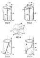
Figure 2 is a split ceramic bore liner according to a first embodiment of the present invention; -
Figure 3 is a split ceramic bore liner according to a second embodiment of the present invention; -
Figure 4 is a detail view of region IV ofFigure 3 ; -
Figure 5 is a split ceramic bore liner according to a third embodiment of the present invention; -
Figure 6 is a split ceramic bore liner according to a fourth embodiment of the present invention; -
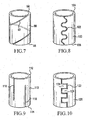
Figure 7 is a split ceramic bore liner according to a fifth embodiment of the present invention; -
Figure 8 is a split ceramic bore liner according to a sixth embodiment of the present invention; -
Figure 9 is a split ceramic bore liner according to a seventh embodiment of the present invention; -
Figure 10 is a split ceramic bore liner according to an eighth embodiment of the present invention; -
Figure 11 is a partial end elevational view of the rotor ofFigure 1 having two different split ceramic bore liners installed therein; and -
Figure 12 illustrates a method of forming a rotor having a ceramic bore liner according to an embodiment of the invention.
Referring now to the drawings, wherein the showings are for purposes of illustrating several presently preferred embodiments of the invention only and not for the purpose of limiting same,Figure 1 illustrates afluid transfer device 10 comprising ahousing 12 having aninterior 14 in which arotor 16 is mounted for rotation.Rotor 16 is supported by first and second sets ofbearings 18 and comprises arotor shaft 20 and arotor body 22.Rotor body 22 includes a plurality ofcylinders 24. two of which are illustrated inFigure 1 . Generally, an odd number of cylinders will be provided.Rotor body 22 includes a balance land orfront face 26 having first andsecond openings 28 communicating withcylinders 24. First andsecond pistons 30 are mounted for sliding movement incylinders 24 in an axial direction generally parallel to theaxis 32 ofrotor shaft 20. Each ofpistons 30 includes afirst end 34 facingopenings 28 and asecond end 36 projecting fromrotor body 22 and terminating in ashoe assembly 38. A cam plate 40 (also known as a swash plate) is mounted ininterior 14 ofhousing 12, andshoe assembly 38 are held against thecam plate 40.
Each of thecylinders 24 includes aceramic bore liner 42, having, as illustrated inFigure 2 , at least one split 44 and alongitudinal axis 46.Bore liners 42 may be formed from a ceramic material such as, but not limited to alumina, silicon nitride, silicon carbide, or a cermet such as tungsten-carbide cobalt. For certain types of processing, such as electro-discharge machining (EDM), it may be desirable to use a ceramic such as the material disclosed inU.S. Patent No. 5,177,037 to Schuldies . Other ceramic materials known to those of ordinary skill in the art may also be used based on the operating requirements of the fluid transfer device without departing from the present invention.
With continued reference toFigure 2 ,bore liner 42 includes asplit 44 extending from afirst end 48 to asecond end 50. Thesplit 44 is defined by afirst wall 52 spaced from asecond wall 54. First andsecond walls axis 46 as illustrated inFigure 2 makingsplit 44 generally normal toaxis 46. Whenbore liner 42 is installed in a rotor,first wall 52 andsecond wall 54 may remain spaced, as shown inbore 60 inFigure 12 , or may contact one another when thebore liner 42 is compressed to fit within a bore as illustrated inbore 62. Generally all bore liners in a given rotor will have similar gaps;Figure 12 includes one bore liner having spaced walls and a second bore liner having a gap between two walls for illustration purposes only.
Split 42 may be formed in any of a variety of ways. For example, an uncured ceramic cylinder may be provided with a suitable split prior to densification. Alternately, a densified ceramic cylinder can be cut or otherwise machined to produce a split. Such cutting operations may be carried out by, for example, diamond grinding, abrasive water jet cutting, laser cutting, ultrasonic machining or electro-discharge machining. The use of the term "split" herein is intended to describe the result of such an operation and is not intended to specify or limit the manner in which the split is formed.
In operation,pistons 30 reciprocate withinbores 24 asrotor 20 rotates and fluid moves into and exits frombores 24.Pistons 30 have an outer diameter slightly smaller than the inner diameter ofbores 24, therefore a certain amount of leakage occurs between thepistons 30 and walls ofcylinders 24 during use. Advantageously, this leakage provides lubrication forpistons 30 and also helps to cool the pistons and the rotors. Leakage occurs whether or not a split is provided inbore liner 42; however split 44 can controllably increase leakage which in turn may help to better cool the pistons and rotor.
The distance betweenfirst wall 50 andsecond wall 52 is selected to provide for a desired degree of leakage and will be selected based on the anticipated operating temperatures and lubrication requirements of the rotor. The split can be sized so thatfirst wall 50 andsecond wall 52 will contact one another in use, as illustrated inbore 60 ofFigure 11 , when it is important to control leakage. Alternately, the split can be sized so thatfirst wall 50 andsecond wall 52 remain spaced after thebore liner 42 is installed as illustrated inbore 62 inFigure 11 . Notably, whetherfirst wall 50 andsecond wall 52 contact one another in use or remain spaced, the presence ofsplit 44 helps to relieve stresses that occur during installation and use and should reduce the failure rate of the cylindrical bore liner.
A second embodiment of the present invention is illustrated inFigures 3 and 4 wherein elements common to the first embodiment are identified using the same reference numerals. Elements related to elements of the first embodiment are identified with a prime. In this embodiment,ceramic bore liner 42 includes asplit 44' defined by a first wall 52' and a second wall 54' where the first and second walls 52', 54' lay in parallel planes both of which pass to the same side oflongitudinal axis 46 ofbore liner 42. This arrangement may help maintain a more constant rate of leakage even as the distance between first wall 50' and second wall 52' changes with temperature and operating conditions.
A third embodiment of the invention is illustrated inFigure 5 . In this embodiment, abore liner 70 includes asplit 72 that extends from afirst end 74 to asecond end 76 ofbore liner 70. In this embodiment,first end 75 ofsplit 72 is circumferentially spaced fromsecond end 77 while split 72 is generally linear.
A fourth embodiment of the invention is illustrated inFigure 6 . In this embodiment, abore liner 80 has asplit 82 that extends from afirst end 84 to asecond end 86 ofbore liner 80 and includes first and second bends 88. Like the third embodiment discussed above, the ends of thesplit 82 ofbore liner 80, as well as first andsecond bends 88, are circumferentially spaced.
A fifth embodiment of the invention is illustrated inFigure 7 wherein abore liner 90 having ahelical split 92 is disclosed which split extends from afirst end 94 to asecond end 96 ofbore 90. The use of such ahelical split 92 should reduce the likelihood of liner failure and at the same time may help direct a leakage flow around the circumference ofcylinder 24 and thus provide more even cooling. The configuration of the split could also be varied to provide greater or lesser cooling in different areas depending on the cooling needs of a particular cylinder and rotor. Helical split 92, by directing the leakage flow around the periphery of the cylinder, may also provide more even lubrication and help avoid the condition known as hydraulic lock. Hydraulic lock occurs when pressure due to leakage flow becomes greater on one side of a piston than on the other causing increased friction between the piston an cylinder on the under-lubricated side and often leading to piston or bore damage.
Figure 8 illustrates a sixth embodiment of the present invention in which abore liner 100 includes aserpentine split 102 extending from afirst end 104 to asecond end 106 of thebore liner 100. This embodiment provides many benefits of the previous embodiments while at the same time may be useful for limiting a leakage flow from one end of the bore liner to the other due to the winding path that the leaking fluid must traverse.
Figure 9 illustrates a seventh embodiment of the present invention in which abore liner 110 includes afirst end 112 and asecond end 114. Afirst split 116 extends fromfirst end 112 ofbore liner 110 but does not extend as far assecond end 114; asecond split 118 extends fromsecond end 114 ofbore liner 110 but does not extend as far asfirst end 112. More than two splits may be provided, and the circumferential spacing of the splits may be varied. This arrangement may also help to minimize leakage flow while still improving the flexibility of and reducing the fracturing of the ceramic bore liner.
Figure 10 illustrates an eighth embodiment of the invention wherein abore liner 120 is provided having asplit 122 that defines a plurality of generallyrectangular teeth 124 on either side ofsplit 122.
Figure 11 illustrates an example not forming part of the invention wherein aceramic bore liner 130 is provided having afirst split 132 and asecond split 134 each extending from afirst end 136 to asecond end 138 of thebore liner 130. While generallylinear splits splits bore liner 130 can generally not be shrink fitted or press fitted intobore 24 as may optionally be done with the bore liners of the previous embodiments. Instead, it will generally be necessary to brazebore liner 130 in place.
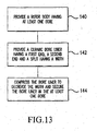
A method of installing a ceramic bore liner according to one of the first through eighth embodiments of the invention will be described in connection withFigure 13 . As illustrated in this figure, a method of installing a ceramic bore liner includes the steps of providing a rotor body having at least one bore at astep 140, providing a ceramic bore liner having a first end, a second end and a split at astep 142 and compressing the bore liner to decrease the width of the split and securing the bore liner in the at least one bore at astep 144.
The present invention has been described herein in terms of several preferred embodiments. Variations and additions to these embodiments will become apparent to those skilled in the relevant arts upon a reading of the foregoing descriptions. It is intended that all such obvious modifications and additions form a part of the present invention to the extent they fall within the scope of the several claims appended hereto.
Claims (5)
- A rotor body (22) having a plurality of cylindrical bores (24) each adapted to receive a piston (30) for reciprocating movement therein, each of said bores (30) being lined with a single ceramic liner (42,70,80,90,100,11,120,130) characterised in that said ceramic liner comprises a single piece, said single piece having a first end (48,74,94,104,1,12,136), a second end (50,76,86,96,1.06,114,138) and a sidewall having a split (44,44',72,82,92,102,116,122,132), said split (44,44',72,92,102,116,122, 132) extending axially from said first end (48,74,84,94,104,112,136) toward said second end (50,76,86,96,106,114,138).
- The rotor body of claim 1 wherein said split (44,44',72,82,92,102,116,122,132) is defined by a first wall (52,52') spaced from a second wall (54,54').
- The rotor body of claim 1 wherein said split (44,44',72,82,92,102,116,122,132) is defined by a first wall (52,52') in contact with a second wall (54,54').
- The rotor body of claim 1 including a layer of braze between each of said ceramic liners (42,70,80,90,100,11,120,130) and each of said bores (30).
- A method of forming a rotor having a ceramic bore liner comprising the steps of:providing a rotor body having at least one bore (140); and characterised by forming a split in an uncured ceramic cylinder;densifying the ceramic cylinder to provide a ceramic bore liner having a first end, a second end and a split having a width (142); andcompressing the bore liner to decrease the width and securing the bore liner in the at least one bore (144).
Applications Claiming Priority (1)
| Application Number | Priority Date | Filing Date | Title |
|---|---|---|---|
| US11/192,268 US7469626B2 (en) | 2005-07-29 | 2005-07-29 | Split ceramic bore liner, rotor body having a split ceramic bore liner and method of lining a rotor bore with a split ceramic bore liner |
Publications (3)
| Publication Number | Publication Date |
|---|---|
| EP1748192A2 EP1748192A2 (en) | 2007-01-31 |
| EP1748192A3 EP1748192A3 (en) | 2008-03-26 |
| EP1748192B1 true EP1748192B1 (en) | 2014-08-27 |
Family
ID=36940379
Family Applications (1)
| Application Number | Title | Priority Date | Filing Date |
|---|---|---|---|
| EP06118055.0A Expired - Fee Related EP1748192B1 (en) | 2005-07-29 | 2006-07-28 | Split ceramic bore liner |
Country Status (2)
| Country | Link |
|---|---|
| US (1) | US7469626B2 (en) |
| EP (1) | EP1748192B1 (en) |
Families Citing this family (5)
| Publication number | Priority date | Publication date | Assignee | Title |
|---|---|---|---|---|
| CN101541461B (en) | 2007-07-24 | 2012-07-18 | 布林克曼泵业K.H.布林克曼两合公司 | Method for producing a machine housing with a surface-hardened fluid chamber |
| US7992652B2 (en) * | 2009-02-05 | 2011-08-09 | Atlas Copco Secoroc Llc | Fluid distributor cylinder for percussive drills |
| US10309380B2 (en) | 2011-11-16 | 2019-06-04 | Ocean Pacific Technologies | Rotary axial piston pump |
| US9322401B2 (en) * | 2014-02-10 | 2016-04-26 | General Electric Company | Linear compressor |
| US10094364B2 (en) | 2015-03-24 | 2018-10-09 | Ocean Pacific Technologies | Banded ceramic valve and/or port plate |
Family Cites Families (26)
| Publication number | Priority date | Publication date | Assignee | Title |
|---|---|---|---|---|
| US813536A (en) * | 1904-03-28 | 1906-02-27 | Max Thier | Cylinder for internal-combustion motors and the like. |
| US2170015A (en) * | 1938-06-09 | 1939-08-22 | Ford Motor Co | Internal combustion engine |
| US2283424A (en) * | 1939-03-20 | 1942-05-19 | Thompson Prod Inc | Cylinder liner sleeve |
| US2635021A (en) * | 1941-07-03 | 1953-04-14 | Alward Kenneth Cutler | Cylinder liner |
| US3550233A (en) * | 1968-05-08 | 1970-12-29 | Lucas Industries Ltd | Methods of making rotors for piston type hydraulic pumps and motors |
| GB1235696A (en) | 1968-05-24 | 1971-06-16 | Laser Eng Dev Ltd | Reciprocating hydraulic pumps and motors of the axial type |
| US3709108A (en) * | 1970-11-27 | 1973-01-09 | Gen Signal Corp | Steel cylinder barrel having bonded bronze-iron liners |
| JPS5413852B2 (en) | 1972-01-17 | 1979-06-02 | ||
| JPS5675940A (en) * | 1979-11-21 | 1981-06-23 | Toshiba Corp | Cylinder for internal combustion engine |
| US4465040A (en) | 1980-12-05 | 1984-08-14 | Mack Trucks, Inc. | Valve guide insert |
| JPS58167848A (en) | 1982-03-27 | 1983-10-04 | Toyota Motor Corp | Longitudinal split type sleeve |
| DE3437999A1 (en) | 1984-10-17 | 1986-04-17 | Sigri GmbH, 8901 Meitingen | Cylinder for a working machine |
| NL8501315A (en) * | 1985-05-08 | 1986-12-01 | Multinorm Bv | PUMP. |
| GB8703330D0 (en) * | 1987-02-13 | 1987-03-18 | Ae Plc | Ceramic cylinders |
| US5177037A (en) | 1991-05-21 | 1993-01-05 | Industrial Ceramic Technology, Inc. | High fracture toughness electro-discharge machineable ceramic whisker reinforced ceramic composites and tooling made therefrom |
| DE4301126C2 (en) | 1993-01-18 | 1995-05-24 | Danfoss As | Method for mounting a liner in a base body of a hydraulic machine and hydraulic machine |
| US5581881A (en) * | 1994-10-17 | 1996-12-10 | Caterpillar Inc. | Method of making a cylinder barrel having ceramic bore liners |
| JPH0942150A (en) | 1995-07-27 | 1997-02-10 | Toyota Autom Loom Works Ltd | Variable displacement type swash plate compressor |
| JPH09324694A (en) * | 1996-06-06 | 1997-12-16 | Toyota Motor Corp | Cylinder block with multiple cylinders |
| US6254948B1 (en) | 1996-09-09 | 2001-07-03 | Phoenix Aktiengesellschaft | Slit protection for a tubular body |
| US5870990A (en) * | 1997-09-02 | 1999-02-16 | Ford Global Technologies, Inc. | Cylinder bore liner for an internal combustion engine |
| SE514243C2 (en) | 1998-06-09 | 2001-01-29 | Flow Holdings Gmbh Sagl Llc | Method of providing a high-pressure press as well as a high-pressure press |
| FR2779489B1 (en) | 1998-06-09 | 2001-04-06 | Valeo | DEVICE FOR HYDRAULICALLY CONTROLLING A BRAKE OR CLUTCH, PARTICULARLY FOR A MOTOR VEHICLE |
| DE10051420B4 (en) | 2000-10-17 | 2009-03-05 | Valeo Compressor Europe Gmbh | Cylinder block of an axial piston compressor with extended cylinder surface |
| DE10223844B4 (en) * | 2002-05-28 | 2013-04-04 | Danfoss A/S | Water hydraulic machine |
| US6802244B1 (en) | 2003-04-25 | 2004-10-12 | Sauer-Danfoss, Inc. | Hydrostatic cylinder block and method of making the same |
-
2005
- 2005-07-29 US US11/192,268 patent/US7469626B2/en not_active Expired - Fee Related
-
2006
- 2006-07-28 EP EP06118055.0A patent/EP1748192B1/en not_active Expired - Fee Related
Also Published As
| Publication number | Publication date |
|---|---|
| EP1748192A2 (en) | 2007-01-31 |
| EP1748192A3 (en) | 2008-03-26 |
| US20070039157A1 (en) | 2007-02-22 |
| US7469626B2 (en) | 2008-12-30 |
Similar Documents
| Publication | Publication Date | Title |
|---|---|---|
| US10774828B1 (en) | Composite valve seat system and method | |
| EP1748192B1 (en) | Split ceramic bore liner | |
| EP0731301A1 (en) | Seal ring and seal device | |
| US20070009367A1 (en) | Close fit cylinder and plunger | |
| US11384756B1 (en) | Composite valve seat system and method | |
| US5704272A (en) | Axial piston energy converting device | |
| EP2678588B1 (en) | Axial piston pump with pistons having metallic sealing rings | |
| CN112814893A (en) | Hydraulic piston machine | |
| JP3979313B2 (en) | High pressure pump | |
| JP2000205142A (en) | Liquid-operated positive-displacement machine, particularly, positive-displacement pump | |
| US10094364B2 (en) | Banded ceramic valve and/or port plate | |
| US11808360B2 (en) | Oil scraper ring for a piston rod | |
| JPS5923160A (en) | Assembly of piston ring | |
| EP3191743B1 (en) | Piston arrangement | |
| CN100351515C (en) | Rotary radial piston machine | |
| CN211573723U (en) | Long-life piston ring sealing system | |
| CN106862858B (en) | Method for producing a recess in a drive shaft, drive shaft and axial piston machine | |
| EP3555476B1 (en) | Pump sealing | |
| JPH08247021A (en) | Hydraulic piston pump and hydraulic piston motor | |
| WO2018088487A1 (en) | Cylinder block, and swashplate type hydraulic rotating device provided with same | |
| JP2003343424A (en) | Swash plate type fluid pump/motor | |
| JP2003138983A (en) | Piston assembly of free piston internal combustion engine | |
| EP3109471A1 (en) | Water-hydraulic machine | |
| US11293451B2 (en) | Coating for compressor outlet housing | |
| EP2587058B1 (en) | Bent axis type hydraulic rotating machine |
Legal Events
| Date | Code | Title | Description |
|---|---|---|---|
| PUAI | Public reference made under article 153(3) epc to a published international application that has entered the european phase |
Free format text: ORIGINAL CODE: 0009012 |
|
| AK | Designated contracting states |
Kind code of ref document: A2 Designated state(s): AT BE BG CH CY CZ DE DK EE ES FI FR GB GR HU IE IS IT LI LT LU LV MC NL PL PT RO SE SI SK TR |
|
| AX | Request for extension of the european patent |
Extension state: AL BA HR MK YU |
|
| PUAL | Search report despatched |
Free format text: ORIGINAL CODE: 0009013 |
|
| AK | Designated contracting states |
Kind code of ref document: A3 Designated state(s): AT BE BG CH CY CZ DE DK EE ES FI FR GB GR HU IE IS IT LI LT LU LV MC NL PL PT RO SE SI SK TR |
|
| AX | Request for extension of the european patent |
Extension state: AL BA HR MK YU |
|
| RIC1 | Information provided on ipc code assigned before grant |
Ipc: F04B 53/16 20060101AFI20060912BHEP Ipc: F04B 1/20 20060101ALI20080215BHEP Ipc: F16J 10/04 20060101ALI20080215BHEP |
|
| 17P | Request for examination filed |
Effective date: 20080916 |
|
| AKX | Designation fees paid |
Designated state(s): DE FR GB |
|
| 17Q | First examination report despatched |
Effective date: 20081121 |
|
| GRAP | Despatch of communication of intention to grant a patent |
Free format text: ORIGINAL CODE: EPIDOSNIGR1 |
|
| INTG | Intention to grant announced |
Effective date: 20140429 |
|
| GRAS | Grant fee paid |
Free format text: ORIGINAL CODE: EPIDOSNIGR3 |
|
| GRAA | (expected) grant |
Free format text: ORIGINAL CODE: 0009210 |
|
| AK | Designated contracting states |
Kind code of ref document: B1 Designated state(s): DE FR GB |
|
| REG | Reference to a national code |
Ref country code: GB Ref legal event code: FG4D |
|
| REG | Reference to a national code |
Ref country code: DE Ref legal event code: R096 Ref document number: 602006042828 Country of ref document: DE Effective date: 20141009 |
|
| REG | Reference to a national code |
Ref country code: DE Ref legal event code: R097 Ref document number: 602006042828 Country of ref document: DE |
|
| REG | Reference to a national code |
Ref country code: FR Ref legal event code: PLFP Year of fee payment: 10 |
|
| PLBE | No opposition filed within time limit |
Free format text: ORIGINAL CODE: 0009261 |
|
| STAA | Information on the status of an ep patent application or granted ep patent |
Free format text: STATUS: NO OPPOSITION FILED WITHIN TIME LIMIT |
|
| PGFP | Annual fee paid to national office [announced via postgrant information from national office to epo] |
Ref country code: GB Payment date: 20150624 Year of fee payment: 10 |
|
| 26N | No opposition filed |
Effective date: 20150528 |
|
| PGFP | Annual fee paid to national office [announced via postgrant information from national office to epo] |
Ref country code: FR Payment date: 20150624 Year of fee payment: 10 |
|
| PGFP | Annual fee paid to national office [announced via postgrant information from national office to epo] |
Ref country code: DE Payment date: 20150731 Year of fee payment: 10 |
|
| REG | Reference to a national code |
Ref country code: DE Ref legal event code: R119 Ref document number: 602006042828 Country of ref document: DE |
|
| GBPC | Gb: european patent ceased through non-payment of renewal fee |
Effective date: 20160728 |
|
| PG25 | Lapsed in a contracting state [announced via postgrant information from national office to epo] |
Ref country code: DE Free format text: LAPSE BECAUSE OF NON-PAYMENT OF DUE FEES Effective date: 20170201 Ref country code: FR Free format text: LAPSE BECAUSE OF NON-PAYMENT OF DUE FEES Effective date: 20160801 |
|
| REG | Reference to a national code |
Ref country code: FR Ref legal event code: ST Effective date: 20170331 |
|
| PG25 | Lapsed in a contracting state [announced via postgrant information from national office to epo] |
Ref country code: GB Free format text: LAPSE BECAUSE OF NON-PAYMENT OF DUE FEES Effective date: 20160728 |
|
| P01 | Opt-out of the competence of the unified patent court (upc) registered |
Effective date: 20230525 |