EP1748159B1 - Electromagnetically driven valve - Google Patents
Electromagnetically driven valve Download PDFInfo
- Publication number
- EP1748159B1 EP1748159B1 EP06015549A EP06015549A EP1748159B1 EP 1748159 B1 EP1748159 B1 EP 1748159B1 EP 06015549 A EP06015549 A EP 06015549A EP 06015549 A EP06015549 A EP 06015549A EP 1748159 B1 EP1748159 B1 EP 1748159B1
- Authority
- EP
- European Patent Office
- Prior art keywords
- electromagnetically driven
- core
- driven valve
- coil
- electromagnet
- Prior art date
- Legal status (The legal status is an assumption and is not a legal conclusion. Google has not performed a legal analysis and makes no representation as to the accuracy of the status listed.)
- Not-in-force
Links
- 230000005291 magnetic effect Effects 0.000 claims description 29
- 239000000696 magnetic material Substances 0.000 claims description 14
- 230000004907 flux Effects 0.000 description 20
- XEEYBQQBJWHFJM-UHFFFAOYSA-N Iron Chemical compound [Fe] XEEYBQQBJWHFJM-UHFFFAOYSA-N 0.000 description 12
- 238000002485 combustion reaction Methods 0.000 description 7
- 230000007935 neutral effect Effects 0.000 description 7
- 229910000831 Steel Inorganic materials 0.000 description 6
- 229910052742 iron Inorganic materials 0.000 description 6
- 239000010959 steel Substances 0.000 description 6
- 238000003466 welding Methods 0.000 description 5
- 238000006073 displacement reaction Methods 0.000 description 3
- 230000000694 effects Effects 0.000 description 3
- 238000000034 method Methods 0.000 description 3
- 230000003247 decreasing effect Effects 0.000 description 2
- 230000005294 ferromagnetic effect Effects 0.000 description 2
- 230000009471 action Effects 0.000 description 1
- 230000007423 decrease Effects 0.000 description 1
- 239000000446 fuel Substances 0.000 description 1
- 230000007246 mechanism Effects 0.000 description 1
- 239000000203 mixture Substances 0.000 description 1
- 230000004048 modification Effects 0.000 description 1
- 238000012986 modification Methods 0.000 description 1
- 230000001846 repelling effect Effects 0.000 description 1
- 230000004043 responsiveness Effects 0.000 description 1
Images


Classifications
-
- F—MECHANICAL ENGINEERING; LIGHTING; HEATING; WEAPONS; BLASTING
- F01—MACHINES OR ENGINES IN GENERAL; ENGINE PLANTS IN GENERAL; STEAM ENGINES
- F01L—CYCLICALLY OPERATING VALVES FOR MACHINES OR ENGINES
- F01L9/00—Valve-gear or valve arrangements actuated non-mechanically
- F01L9/20—Valve-gear or valve arrangements actuated non-mechanically by electric means
- F01L9/21—Valve-gear or valve arrangements actuated non-mechanically by electric means actuated by solenoids
- F01L2009/2105—Valve-gear or valve arrangements actuated non-mechanically by electric means actuated by solenoids comprising two or more coils
- F01L2009/2109—The armature being articulated perpendicularly to the coils axes
Definitions
- the invention generally relates to an electromagnetically driven valve. More specifically, one embodiment relates to a pivor-type electromagnetically driven valve for an internal combustion engine, which is driven by an elastic force and an electromagnetic force.
- the invention may be used, for example, in the field of electromagnetically driven valves for an internal combustion engine that is provided for a vehicle.
- US Patent No. 6467441 describes a pivot-type electromagnetically driven valve that includes two coils.
- a supporting point is provided in a disc (armature).
- armature In conventional electromagnetically driven valves, a large gap exists between a disc and an electromagnet and a small electromagnetic force is provided at an end portion. As a result of this arrangement, it is difficult to obtain a large initial driving force. Further, it is necessary to increase the amount of electric current to obtain the large initial driving force. But increasing the amount of electric current necessarily increases the amount of consumed electric power.
- Document DE 102 21 015 A1 further discloses an internal combustion engine including cylinders with inlet and outlet valves, a first inlet valve drive having a first degree of adjustability for operating an inlet valve of at least one cylinder and a second inlet valve drive having a second degree of adjustability for operating an inlet valve of the at least one cylinder, the engine includes other cylinders having inlet valves with inlet valve drives having only the second degree of adjustability for operating the inlet valves of the other cylinders.
- Document DE 102 26 010 A1 discloses an electromagnetical actuator for actuating a valve of an internal combustion engine.
- the Actuator includes at least one torsion spring acting on an armature which is electromagnetically operable.
- an electromagnetic valve actuator for actuating movement of a valve in a vehicle engine.
- Said actuator includes a valve assembly operatively connected to the valve for movement therewith.
- the valve assembly includes a shaft connected to the valve.
- Two armature plates are operatively associated with the shaft, and each armature plate includes a permanent magnet.
- An electromagnetic coil is positioned between the two armature plates for selectively electromagnetically pushing and pulling the armature plates.
- Two springs are engaged with the two armature plates, respectively, for biasing the armature plates in opposing directions.
- the permanent magnets are operative to assist the electromagnetic coil in holding the valve in a desired position to reduce power consumption or assisting in repelling the armature for accelerating valve opening or closing.
- Document DE 195 18 056 A1 further discloses a device and a method for controlling armature movement in an electromagnetic circuit.
- Said device includes a holding magnet having a magnet yoke provided with a pole face; a solenoid connected to the magnet yoke; a movably supported armature arranged for reciprocating motion toward and away from the pole face along a motion path; an energizing arrangement for passing a current through the solenoid; a measuring pole leg attached to the magnet yoke; and a measuring pole carried by the measuring pole leg.
- the measuring pole is situated along the motion path of the armature and generates a signal upon passage of the armature by the measuring pole.
- document EP 1 098 072 A1 discloses a method for the control of an electromagnetic actuator coupled to a respective valve and provided with a moving ferromagnetic member connected to at least one point of the valve, a pair of electromagnets disposed on opposite sides with respect to the moving ferromagnetic member and an elastic member adapted to maintain the valve in a rest position.
- the method comprises the stages of detecting an actual position and an actual velocity of the valve, determining a reference position and a reference velocity of the valve and minimising differences between the reference position and the actual position and between the reference velocity and the actual velocity of the valve by means of a feedback control action.
- An electromagnetically driven valve is operated by electromagnetic force.
- the electromagnetically driven valve includes a valve element, an oscillating member, a support member, and an electromagnet.
- the valve element includes a valve shaft, and is reciprocated in the direction the valve shaft extends.
- the oscillating member extends from a driving end that is moved in conjunction with the valve element, to a pivoting end.
- the oscillating member is oscillated around a central axis that extends at the pivoting end.
- the support member supports the pivoting end of the oscillating member.
- the electromagnet is provided so as to face the oscillating member.
- the electromagnet includes a core made of magnetic material, and a coil wound in the core. The coil is offset to a driving end side with respect to a center of the core.
- the coil is offset to the driving end side with respect to the center of the core. Therefore, the width of the flux path is large on the pivoting end side, that is, on the central-axis side. Because the distance between the electromagnet and the oscillating member is short on the pivoting end side, a large electromagnetic force can be obtained when operation of the electromagnetically driven valve is started.
- a protrusion which is made of magnetic material, and which extends toward the oscillating member, may be provided in the core at a portion on the driving end side. In this case, a gap between the core and the oscillating member can be reduced by the protrusion. Therefore, the density of magnetic flux can be increased, and the electromagnetic force can be increased.
- a convex portion may be provided in the core at a weld portion on the driving end side. In this case, iron loss due to welding can be prevented, and the amount of consumed electric power can be reduced.
- an electromagnetically driven valve that can increase the initial driving force.
- FIG. 1 is a cross-sectional view of an electromagnetically driven valve according to a first exemplary embodiment of the invention.
- an electromagnetically driven valve 1 includes a main body 51, an upper electromagnet 60, a lower electromagnet 160, a disc 30, and a valve stem 12.
- the upper electromagnet 60 and the lower electromagnet 160 are fitted to the main body 51.
- the disc 30 is provided between the upper electromagnet 60 and the lower electromagnet 160.
- the valve stem 12 is driven by the disc 30.
- the main body 51 has a U-shape cross section, and serves as a base member. Various elements are fitted to the main body 51.
- the upper electromagnet 60 includes a core 61 made of magnetic material, and a coil 62 wound in the core 61.
- the lower electromagnet 160 includes a core 161 made of magnetic material, and a coil 162 wound in the core 161. When each of the coils 62 and 162 is energized, a magnetic field is generated. The disc 30 is driven by the magnetic field.
- the disc 30 is provided between the upper electromagnet 60 and the lower electromagnet 160, and is attracted to the upper electromagnet 60 or the lower electromagnet 160 by the attraction force (electromagnetic force) thereof. As a result, the disc 30 is reciprocated between the upper electromagnet 60 and the lower electromagnet 160. The reciprocating motion of the disc 30 is transmitted to the valve stem 12.
- the electromagnetically driven valve 1 is operated by electric power.
- the electromagnetically driven valve 1 includes a valve element 14, the main body 51, the disc 30, and the upper and lower electromagnets 60 and 160.
- the valve element 14 includes the valve stem 12 that serves as the valve shaft, and is reciprocated in a direction in which the valve stem 12 extends (i.e., the direction indicated by an arrow 10).
- the main body 51 which serves as the support member, is provided at a position distant from the valve element 14.
- the disc 30 includes a driving end 32 that is moved in conjunction with the valve stem 12, and a pivoting end 33 that is supported by the main body 51 such that the pivoting end 33 can be oscillated.
- the disc 30 is oscillated around a rotational axis 35 that extends at the pivoting end 33.
- the disc 30 serves as the oscillating member.
- the rotational axis 35 serves as the central axis.
- the upper electromagnet 60 and the lower electromagnet 160 are disposed so as to face the disc 30.
- the upper electromagnet 60 includes the core 61 made of magnetic material, and the coil 62 wound in the core 61.
- the lower electromagnet 160 includes the core 161 made of magnetic material, and the coil 162 wound in the core 161.
- the coil 62 is offset to a driving end 32 side (i.e., the side closer to the driving end 32 than to the pivoting end 33) with respect to a central axis 261 of the core 61.
- the coil 162 is also offset to the driving end 32 side with respect to the central axis 261 of the core 161.
- the electromagnetically driven valve 1 in this embodiment constitutes an intake valve or an exhaust valve of an internal combustion engine, such as a gasoline engine or a diesel engine.
- the valve element 14 is used as an intake valve provided in an intake port 18.
- the valve 1 may be applied to the case where the valve element 14 is used as an exhaust valve.
- the electromagnetically driven valve 1 shown in FIG. 1 is a pivot-type electromagnetically driven valve.
- the disc 30 is used as a motion mechanism.
- the main body 51 is provided on a cylinder head 41.
- the lower electromagnet 160 is provided in a lower area of the main body 51.
- the upper electromagnet 60 is provided in an upper area of the main body 51.
- the lower electromagnet 160 includes the core 161 made of iron, and the coil 162 wound in the core 161. By supplying electric current to the coil 162, the magnetic field is generated around the coil 162.
- the disc 30 is attracted to the lower electromagnet 160 by this magnetic field.
- the upper electromagnet 60 includes the core 61 made of iron, and the coil 62 wound in the core 61. By supplying electric current to the coil 62, the magnetic field is generated around the coil 62. The disc 30 is attracted to the upper electromagnet 60 by this magnetic field.
- the coil 62 of the upper electromagnet 60 may be connected to the coil 162 of the lower electromagnet 160. In this case, the coils 62 and 162 form a single coil. Alternatively, the coil 62 may be separated from the coil 162.
- the number of turns of the coil 62 wound in the core 61 is not limited to a specific number. Also, the number of turns of the coil 162 wound in the core 161 is not limited to a specific number.
- the disc 30 includes an arm portion 31 and a bearing portion 38.
- the arm portion 31 extends from the driving end 32 to the pivoting end 33.
- the arm portion 31 is attracted by the upper electromagnet 60 or the lower electromagnet 160.
- the arm portion 31 is pivoted (oscillated) in a direction shown by an arrow 30d.
- the bearing portion 38 is fitted to an end portion of the arm portion 31.
- the arm portion 31 is pivoted around the bearing portion 38.
- the arm portion 31 can pivot such that an upper surface 131 of the arm portion 31 contacts the upper electromagnet 60, and such that a lower surface 231 of the arm portion 31 contacts the lower electromagnet 160, and a cap 112.
- the bearing portion 38 has a cylindrical shape.
- a torsion bar 36 is provided inside the bearing portion 38.
- One end portion of the torsion bar 36 is spline fitting to the main body 51.
- the other end portion of the torsion bar 36 is fitted to the bearing portion 38.
- Intake ports 18 are provided in a lower area of the cylinder head 41. Intake air is introduced to a combustion chamber through each intake port 18. That is, an air-fuel mixture or air passes through each intake port 18.
- a valve seat 42 is provided between the intake port 18 and the combustion chamber. The valve seat 42 serves to increase the sealability of the valve clement 14.
- the valve element 14 that is used as an intake valve is fitted to the cylinder head 41.
- the valve element 14 includes the valve stem 12 and a bell portion 13.
- the valve stem 12 extends in the longitudinal direction.
- the bell portion 13 is provided at the end of the valve stem 12.
- the valve stem 12 is fitted to the cap 112 which has a gate shape.
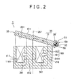
- FIG. 2 is an enlarged cross-sectional view of the lower electromagnet.
- the coil 162 is offset to the driving end 32 side in a direction shown by an arrow 361 with respect to the central axis 261 of the core 161.
- the width of a flux path on the driving end 32 side is denoted by d11.
- the width of the flux path on a pivoting end 33 side i.e., the side closer to the pivoting end 33 (rotational-axis 35) than to the driving end 32
- the width d13 is larger than the width d11.
- the width of the flux path at the center portion of the core 161 is denoted by d12.
- the center of the width d12 is positioned on the left side of the central axis 261.
- the distance or gap between the disc 30 and the lower electromagnet 160 decreases toward the pivoting end 33 from the driving end 32. That is, the gap is large on the driving end 32 side, and the gap is small on the pivoting end 33 side.
- a magnetic circuit 1161 and a magnetic circuit 2161 are generated in the lower electromagnet 160.
- Each of the two magnetic circuits 1161 and 2161 generates the electromagnetic force, which attracts the disc 30 closer to the lower electromagnet 160.
- the force of each magnetic circuit that attracts the disc 30 closer to the lower electromagnet 160 depends on the magnetic flux density in the magnetic circuit and the distance or gap between the lower electromagnet 160 and the disc 30.
- the width d13 on the pivoting end 33 side is large in the core 161. Therefore, a large amount of magnetic flux passes through this large-width portion. Also, the distance between the large-width portion and the disc 30 is short. Accordingly, a large force can be obtained even in the initial stage due to the effect of the magnetic circuit 2161. That is, in the flap type electromagnetically driven valve 1, the gap (distance between the lower electromagnet 160 and the disc 30) at the position distant from the rotational axis 35 is different from the gap at the position close to the rotational axis 35, and the magnetic flux density in these two gaps is uneven.
- the widths of the flux path are set such that saturation of the magnetic flux density can be prevented on the pivoting end 33 side, by shifting the coil 162 to the driving end 32 side. This increases the electromagnetic force, and reduces the amount of electric current that is used, thereby reducing the amount of consumed electric power.
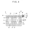
- FIG 3 is a cross-sectional view of a lower electromagnet in a conventional valve.
- the lower electromagnet 160 includes the core 161 and the coil 162.
- the coil 162 is wound in the core 161.
- the conventional lower electromagnet is different from the lower electromagnet 160 shown in FIG 2 in that the width of the flux path on the right side is the same as that on the left side.
- the width of the flux path on the right side of the central axis 261 is the same as that on the left side of the central axis 261 in the core 161. That is, the lower electromagnet 160 in FIG 3 has a symmetric shape.
- the width of the flux path on each of the right and left sides is denoted by "d1''.
- the width of the flux path at the lower portion of the core 161 is denoted by "d2".
- the disc 30 with driving end 32 and pivoting end 33 is placed above the lower electromagnet 160.
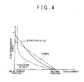
- FIG. 4 is a graph showing the relation between the displacement of the disc and the electromagnetic force in the structure shown in FIG 2 and in the structure shown in FIG. 3 .
- the electromagnetic force is not applied between the upper electromagnet 60 and the lower electromagnet 160, the disc 30 is placed in the "neutral position” in FIG. 4 .
- the disc 30 contacts the lower electromagnet 160, the disc 30 is placed in the "valve-opened position” in FIG. 4 .
- the spring force of the torsion bar 36 is proportional to the displacement of the torsion bar 36. That is, as the torsion bar 36 is displaced from the neutral position, the spring force of the torsion bar 36 increases.
- the force applied between the disc 30 and the lower electromagnet 160 is related to the distance between the disc 30 and the lower electromagnet 160.
- the distance between the disc 30 and the lower electromagnet 160 is small.
- the distance between the disc 30 and the lower electromagnet 160 is long, and therefore the electromagnetic force is small, particularly on the driving end 32 side.
- the electromagnetic force becomes larger. Because the driving end 32 is distant from the rotational axis 35, the electromagnetic force at the driving end 32 has a great effect on the attraction. Accordingly, the electromagnetic force sharply increases near the "valve-opened position" in FIG. 4 .
- the width d13 of the flux path on the pivoting end 33 side is large, unlike the structure shown in FIG. 3 .
- a large electromagnetic force is generated when the disc 30 is placed at the neutral position.
- a large electromagnetic force is generated when the disc 30 is placed in a region near the neutral position, as compared to the structure shown in FIG. 3 .
- the widths of the flux path are set such that saturation of the magnetic flux is prevented, by offsetting the coil 162 to the driving end 32 side. This increases the electromagnetic force, and reduces the amount of used electric current and the amount of consumed electric power.
- the electromagnetically driven valve 1 When the electromagnetically driven valve 1 is operated, electric current is supplied to the coil 62 that constitutes the upper electromagnet 60 or the coil 162 that constitutes the lower electromagnet 160.
- electric current is supplied to the coil 62.
- the magnetic field is generated around the coil 62, and the arm portion 31 of the disc 30, which is made of magnetic material, is attracted to the upper electromagnet 60.
- the arm portion 31 is pivoted upward, the torsion bar 36 is twisted, and the torsion bar 36 is about to move the arm portion 31 in the opposite direction.
- the arm portion 31 is further pivoted upward, and finally, the upper surface 131 contacts the upper electromagnet 60.
- the cap 112 connected to the arm portion 31 and the valve element 14 are moved upward, and finally the bell portion 13 contacts the valve seat 42.
- the valve element 14 is placed in a closed position.
- the arm portion 31 When the valve clement 14 is placed in an opened position, the arm portion 31 needs to be moved downward. In this case, supply of electric current to the coil 62 is stopped, or the amount of electric current supplied to the coil 62 is decreased. As a result, the electromagnetic force that acts between the electromagnet 60 and the arm portion 31 is decreased. Because the torsion force is applied to the arm portion 31 by the torsion bar 36, the torsion force (elastic force) overcomes the electromagnetic force, and the arm portion 31 is moved to the vicinity of the neutral position in FIG. 1 . Then, electric current is supplied to the coil 162 that constitutes the lower electromagnet 160.
- the magnetic field is generated around the coil 162, and the arm portion 31 made of magnetic material is attracted to the lower electromagnet 160.
- the arm portion 31 moves the cap 112 and the valve element 14 downward.
- the attraction force of the coil 162 overcomes the torsion force of the torsion bar 36.
- the lower surface 231 contacts the lower electromagnet 160.
- the valve element 14 is moved downward, and the valve element 14 is placed in the opened position.
- the electromagnetic force can be increased, and the amount of used electric current and the amount of consumed electric power can be reduced.
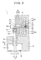
- FIG. 5 is a cross-sectional view of an electromagnetically driven valve according to a second embodiment.
- the electromagnetically driven valve 1 according to the second embodiment is different from the electromagnetically driven valve according to the first embodiment in that a protrusion 661 is provided in the upper electromagnet 60 at a portion on the driving end 32 side, and a protrusion 761 is provided in the lower electromagnet 160 at a portion on the driving end 32 side.
- the coil 62 of the upper electromagnet 60 and the coil 162 of the lower electromagnet 160 are both offset to the driving end 32 side.
- the coil 62 of the upper electromagnet 60 and/or the coil 162 of the lower electromagnet 160 may be offset to the driving end 32 side.
- the protrusions 661 and 761 are made of magnetic material. Each of the protrusions 661 and 761 forms a magnetic circuit. The protrusions 661 and 761 are provided such that the protrusions 661 and 761 do not interfere with the disc 30 that is reciprocated.
- FIG. 6 is a perspective view of a portion of the lower electromagnet provided with the protrusion 761.
- the protrusion 761 is provided so as to contact the core 161.
- the protrusion 761 extends in the depth direction, and has a shape that does not directly interfere with the valve stem 12 and the arm portion 31.
- the protrusion 761 has a thin-plate shape.
- the protrusion 761 is made of magnetic material such as iron.
- FIG. 7 is a cross-sectional view taken along line VII - VII in FIG. 6 .
- the protrusion 76 extends toward the arm portion 31.
- the protrusion 761 forms the magnetic circuit 1161.
- the electromagnetic force is large.
- the area of the flux path on the driving end 32 side is increased.
- the amount of magnetic flux can be increased, and a strortg force can be generated on the driving end 32 side.
- rotational torque is increased by increasing the electromagnetic force at the driving end 32.
- the torque is obtained as the product of the electromagnetic force and the length of the arm. Therefore, by increasing the electromagnetic force at the area distant from the rotational axis 35, the amount of used electric current and the amount of consumed electric power can be reduced.
- FIG. 8 is a cross-sectional view of an electromagnetically driven valve according to a third embodiment of the invention.
- the electromagnetically driven valve 1 according to the third embodiment is different from the electromagnetically driven valve 1 according to the first embodiment in that protrusions 961 are provided in the upper electromagnet 60, and the protrusions 961 are welded to each other.
- Each protrusion 961 is made of magnetic steel plate that constitutes the core 61.
- Protrusions 861 (not shown in FIG. 8 ) are provided also in the lower electromagnet 160.
- the protrusions 861 are provided on the driving end 32 side.
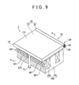
- FIG. 9 is a perspective view of a portion of the lower electromagnet provided with the protrusions 861.
- the core 161 that constitutes the lower electromagnet 160 is formed by stacking a plurality of electromagnetic steel plates.
- the protrusion 861 is provided in each of the electromagnetic steel plates.
- the protrusions 861 in the plurality of electromagnetic steel plates are used to connect the plurality of electromagnetic steel plates. By welding the protrusions 861 to each other, the plurality of electromagnetic steel plates are joined to each other.
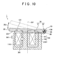
- FIG. 10 is a cross-sectional view taken along line X-X in FIG. 9 .
- the width of magnetic flux on the driving end 32 side is small in the core 161. Therefore, if the protrusions 861 are not provided and the electromagnetic plates of the core 161 are welded at a portion on the driving end 32 side, iron loss may be increased due to welding. Accordingly, in this embodiment, the protrusions 861 used for welding are provided. That is, the protrusions 861 are welded to each other. Therefore, even if iron loss is increased due to welding in the protrusions 861, the magnetic field is not greatly affected. As a result, responsiveness is improved, and the amount of consumed electric power can be reduced.
- FIG. 11 is a cross-sectional view of an electromagnetically driven valve according to a fourth embodiment.
- the electromagnetically driven valve 1 according to the fourth embodiment is different from the electromagnetically driven valve according to the first embodiment in that two discs 30, which are an upper disc and a lower disc, are provided.
- the discs 30 are connected to each other by a stem 1012.
- the coils 62 and 162 are offset to the driving end 32 side.
- the electromagnetically driven valve 1 having the aforementioned configuration according to the fourth embodiment has the same effect as that of the electromagnetically driven valve according to the first embodiment.
- the coil 62 that constitutes the upper electromagnet 60 may be composed of one coil, or a plurality of coils.
- the coil 162 that constitutes the lower electromagnet 160 may also be composed of one coil, or a plurality of coils.
Landscapes
- Engineering & Computer Science (AREA)
- Mechanical Engineering (AREA)
- General Engineering & Computer Science (AREA)
- Valve Device For Special Equipments (AREA)
- Magnetically Actuated Valves (AREA)
Description
- The invention generally relates to an electromagnetically driven valve. More specifically, one embodiment relates to a pivor-type electromagnetically driven valve for an internal combustion engine, which is driven by an elastic force and an electromagnetic force. The invention may be used, for example, in the field of electromagnetically driven valves for an internal combustion engine that is provided for a vehicle.
-
US Patent No. 6467441 describes a pivot-type electromagnetically driven valve that includes two coils. In the electromagnetically driven valve, a supporting point is provided in a disc (armature). In conventional electromagnetically driven valves, a large gap exists between a disc and an electromagnet and a small electromagnetic force is provided at an end portion. As a result of this arrangement, it is difficult to obtain a large initial driving force. Further, it is necessary to increase the amount of electric current to obtain the large initial driving force. But increasing the amount of electric current necessarily increases the amount of consumed electric power. - Document
DE 102 21 015 A1 further discloses an internal combustion engine including cylinders with inlet and outlet valves, a first inlet valve drive having a first degree of adjustability for operating an inlet valve of at least one cylinder and a second inlet valve drive having a second degree of adjustability for operating an inlet valve of the at least one cylinder, the engine includes other cylinders having inlet valves with inlet valve drives having only the second degree of adjustability for operating the inlet valves of the other cylinders. - Document
DE 102 26 010 A1 discloses an electromagnetical actuator for actuating a valve of an internal combustion engine. The Actuator includes at least one torsion spring acting on an armature which is electromagnetically operable. - Further, from document
US 2002/0069842 A1 an electromagnetic valve actuator for actuating movement of a valve in a vehicle engine is known. Said actuator includes a valve assembly operatively connected to the valve for movement therewith. The valve assembly includes a shaft connected to the valve. Two armature plates are operatively associated with the shaft, and each armature plate includes a permanent magnet. An electromagnetic coil is positioned between the two armature plates for selectively electromagnetically pushing and pulling the armature plates. Two springs are engaged with the two armature plates, respectively, for biasing the armature plates in opposing directions. The permanent magnets are operative to assist the electromagnetic coil in holding the valve in a desired position to reduce power consumption or assisting in repelling the armature for accelerating valve opening or closing. - Document
DE 195 18 056 A1 further discloses a device and a method for controlling armature movement in an electromagnetic circuit. Said device includes a holding magnet having a magnet yoke provided with a pole face; a solenoid connected to the magnet yoke; a movably supported armature arranged for reciprocating motion toward and away from the pole face along a motion path; an energizing arrangement for passing a current through the solenoid; a measuring pole leg attached to the magnet yoke; and a measuring pole carried by the measuring pole leg. The measuring pole is situated along the motion path of the armature and generates a signal upon passage of the armature by the measuring pole. - Finally, document
EP 1 098 072 A1 discloses a method for the control of an electromagnetic actuator coupled to a respective valve and provided with a moving ferromagnetic member connected to at least one point of the valve, a pair of electromagnets disposed on opposite sides with respect to the moving ferromagnetic member and an elastic member adapted to maintain the valve in a rest position. The method comprises the stages of detecting an actual position and an actual velocity of the valve, determining a reference position and a reference velocity of the valve and minimising differences between the reference position and the actual position and between the reference velocity and the actual velocity of the valve by means of a feedback control action. - In view of the above shortcoming attendant with the conventional electromagnetically driven valve, it is an object of the invention to provide an electromagnetically driven valve that can increase the initial driving force.
- An electromagnetically driven valve according to an embodiment of the invention is operated by electromagnetic force. The electromagnetically driven valve includes a valve element, an oscillating member, a support member, and an electromagnet. The valve element includes a valve shaft, and is reciprocated in the direction the valve shaft extends. The oscillating member extends from a driving end that is moved in conjunction with the valve element, to a pivoting end. The oscillating member is oscillated around a central axis that extends at the pivoting end. The support member supports the pivoting end of the oscillating member. The electromagnet is provided so as to face the oscillating member. The electromagnet includes a core made of magnetic material, and a coil wound in the core. The coil is offset to a driving end side with respect to a center of the core.
- In the electromagnetically driven valve having the aforementioned configuration, the coil is offset to the driving end side with respect to the center of the core. Therefore, the width of the flux path is large on the pivoting end side, that is, on the central-axis side. Because the distance between the electromagnet and the oscillating member is short on the pivoting end side, a large electromagnetic force can be obtained when operation of the electromagnetically driven valve is started.
- A protrusion which is made of magnetic material, and which extends toward the oscillating member, may be provided in the core at a portion on the driving end side. In this case, a gap between the core and the oscillating member can be reduced by the protrusion. Therefore, the density of magnetic flux can be increased, and the electromagnetic force can be increased.
- A convex portion may be provided in the core at a weld portion on the driving end side. In this case, iron loss due to welding can be prevented, and the amount of consumed electric power can be reduced.
- According to one exemplary embodiment of the invention, it is possible to provide an electromagnetically driven valve that can increase the initial driving force.
- The foregoing and further objects, features and advantages of the invention will become apparent from the following description of example embodiments with reference to the accompanying drawings, wherein the same or corresponding portion are denoted by the same reference numerals and wherein:
-
FIG. 1 is a cross-sectional view of an electromagnetically driven valve according to a first embodiment of the invention; -
FIG. 2 is an enlarged cross-sectional view of a lower electromagnet; -
FIG. 3 is a cross-sectional view of a conventional lower electromagnet; -
FIG. 4 is a graph showing the relation between the displacement of a disc and an electromagnetic force in structures shown inFIG 2 andFIG. 3 ; -
FIG. 5 is a cross-sectional view of an electromagnetically driven valve according to a second embodiment of the invention; -
FIG. 6 is a perspective view of a portion of a lower electromagnet provided with a protrusion; -
FIG. 7 is a cross-sectional view taken along line VII-VII inFIG. 6 ; -
FIG 8 is a cross-sectional view of an electromagnetically driven valve according to a third embodiment of the invention; -
FIG. 9 is a perspective view of a portion of a lower electromagnet provided with protrusions; -
FIG. 10 is a cross-sectional view taken along line X-X inFIG 9 ; and -
FIG. 11 is a cross-sectional view of an electromagnetically driven valve according to a fourth embodiment of the invention. - Hereinafter, exemplary embodiments of the invention will be described with reference to the drawings. In the following embodiments, the same and corresponding portions are denoted by the same reference numerals, and the description thereof will not be repeated.
-
FIG. 1 is a cross-sectional view of an electromagnetically driven valve according to a first exemplary embodiment of the invention. As shown inFIG. 1 , an electromagnetically driven valve 1 includes amain body 51, anupper electromagnet 60, alower electromagnet 160, adisc 30, and avalve stem 12. Theupper electromagnet 60 and thelower electromagnet 160 are fitted to themain body 51. Thedisc 30 is provided between theupper electromagnet 60 and thelower electromagnet 160. The valve stem 12 is driven by thedisc 30. - The
main body 51 has a U-shape cross section, and serves as a base member. Various elements are fitted to themain body 51. Theupper electromagnet 60 includes a core 61 made of magnetic material, and acoil 62 wound in thecore 61. Thelower electromagnet 160 includes acore 161 made of magnetic material, and acoil 162 wound in thecore 161. When each of thecoils disc 30 is driven by the magnetic field. - The
disc 30 is provided between theupper electromagnet 60 and thelower electromagnet 160, and is attracted to theupper electromagnet 60 or thelower electromagnet 160 by the attraction force (electromagnetic force) thereof. As a result, thedisc 30 is reciprocated between theupper electromagnet 60 and thelower electromagnet 160. The reciprocating motion of thedisc 30 is transmitted to thevalve stem 12. - The electromagnetically driven valve 1 is operated by electric power. The electromagnetically driven valve 1 includes a
valve element 14, themain body 51, thedisc 30, and the upper andlower electromagnets valve element 14 includes thevalve stem 12 that serves as the valve shaft, and is reciprocated in a direction in which thevalve stem 12 extends (i.e., the direction indicated by an arrow 10). Themain body 51, which serves as the support member, is provided at a position distant from thevalve element 14. Thedisc 30 includes a drivingend 32 that is moved in conjunction with thevalve stem 12, and a pivotingend 33 that is supported by themain body 51 such that the pivotingend 33 can be oscillated. Thedisc 30 is oscillated around arotational axis 35 that extends at the pivotingend 33. Thedisc 30 serves as the oscillating member. Therotational axis 35 serves as the central axis. Theupper electromagnet 60 and thelower electromagnet 160 are disposed so as to face thedisc 30. Theupper electromagnet 60 includes the core 61 made of magnetic material, and thecoil 62 wound in thecore 61. Thelower electromagnet 160 includes thecore 161 made of magnetic material, and thecoil 162 wound in thecore 161. Thecoil 62 is offset to a drivingend 32 side (i.e., the side closer to the drivingend 32 than to the pivoting end 33) with respect to acentral axis 261 of thecore 61. Thecoil 162 is also offset to the drivingend 32 side with respect to thecentral axis 261 of thecore 161. - The electromagnetically driven valve 1 in this embodiment constitutes an intake valve or an exhaust valve of an internal combustion engine, such as a gasoline engine or a diesel engine. In this embodiment, the
valve element 14 is used as an intake valve provided in anintake port 18. However, the valve 1 may be applied to the case where thevalve element 14 is used as an exhaust valve. - The electromagnetically driven valve 1 shown in
FIG. 1 is a pivot-type electromagnetically driven valve. Thedisc 30 is used as a motion mechanism. Themain body 51 is provided on acylinder head 41. Thelower electromagnet 160 is provided in a lower area of themain body 51. Theupper electromagnet 60 is provided in an upper area of themain body 51. Thelower electromagnet 160 includes thecore 161 made of iron, and thecoil 162 wound in thecore 161. By supplying electric current to thecoil 162, the magnetic field is generated around thecoil 162. Thedisc 30 is attracted to thelower electromagnet 160 by this magnetic field. - The
upper electromagnet 60 includes the core 61 made of iron, and thecoil 62 wound in thecore 61. By supplying electric current to thecoil 62, the magnetic field is generated around thecoil 62. Thedisc 30 is attracted to theupper electromagnet 60 by this magnetic field. - The
coil 62 of theupper electromagnet 60 may be connected to thecoil 162 of thelower electromagnet 160. In this case, thecoils coil 62 may be separated from thecoil 162. The number of turns of thecoil 62 wound in thecore 61 is not limited to a specific number. Also, the number of turns of thecoil 162 wound in thecore 161 is not limited to a specific number. - The
disc 30 includes anarm portion 31 and a bearingportion 38. Thearm portion 31 extends from the drivingend 32 to the pivotingend 33. Thearm portion 31 is attracted by theupper electromagnet 60 or thelower electromagnet 160. As a result, thearm portion 31 is pivoted (oscillated) in a direction shown by anarrow 30d. The bearingportion 38 is fitted to an end portion of thearm portion 31. Thearm portion 31 is pivoted around the bearingportion 38. Thearm portion 31 can pivot such that anupper surface 131 of thearm portion 31 contacts theupper electromagnet 60, and such that alower surface 231 of thearm portion 31 contacts thelower electromagnet 160, and acap 112. - The bearing
portion 38 has a cylindrical shape. Atorsion bar 36 is provided inside the bearingportion 38. One end portion of thetorsion bar 36 is spline fitting to themain body 51. The other end portion of thetorsion bar 36 is fitted to the bearingportion 38. Thus, when the bearingportion 38 is about to pivot, a force resisting the movement is applied to the bearingportion 38 from thetorsion bar 36. Thus, the bearingportion 38 is always urged toward a neutral position. The drivingend 32 of thedisc 30 presses thevalve stem 12 via thecap 112. The valve stem 12 is guided by astem guide 43. -
Intake ports 18 are provided in a lower area of thecylinder head 41. Intake air is introduced to a combustion chamber through eachintake port 18. That is, an air-fuel mixture or air passes through eachintake port 18. Avalve seat 42 is provided between theintake port 18 and the combustion chamber. Thevalve seat 42 serves to increase the sealability of thevalve clement 14. - The
valve element 14 that is used as an intake valve is fitted to thecylinder head 41. Thevalve element 14 includes thevalve stem 12 and abell portion 13. The valve stem 12 extends in the longitudinal direction. Thebell portion 13 is provided at the end of thevalve stem 12. The valve stem 12 is fitted to thecap 112 which has a gate shape. -
FIG. 2 is an enlarged cross-sectional view of the lower electromagnet. As shown inFIG. 2 , thecoil 162 is offset to the drivingend 32 side in a direction shown by anarrow 361 with respect to thecentral axis 261 of thecore 161. The width of a flux path on the drivingend 32 side is denoted by d11. The width of the flux path on a pivotingend 33 side (i.e., the side closer to the pivoting end 33 (rotational-axis 35) than to the driving end 32) is denoted by d13. The width d13 is larger than the width d11. The width of the flux path at the center portion of thecore 161 is denoted by d12. The center of the width d12 is positioned on the left side of thecentral axis 261. The distance or gap between thedisc 30 and thelower electromagnet 160 decreases toward the pivotingend 33 from the drivingend 32. That is, the gap is large on the drivingend 32 side, and the gap is small on the pivotingend 33 side. In thelower electromagnet 160, amagnetic circuit 1161 and amagnetic circuit 2161 are generated. Each of the twomagnetic circuits disc 30 closer to thelower electromagnet 160. The force of each magnetic circuit that attracts thedisc 30 closer to thelower electromagnet 160 depends on the magnetic flux density in the magnetic circuit and the distance or gap between thelower electromagnet 160 and thedisc 30. In this embodiment, because thecoil 162 is offset to the drivingend 32 side, the width d13 on the pivotingend 33 side is large in thecore 161. Therefore, a large amount of magnetic flux passes through this large-width portion. Also, the distance between the large-width portion and thedisc 30 is short. Accordingly, a large force can be obtained even in the initial stage due to the effect of themagnetic circuit 2161. That is, in the flap type electromagnetically driven valve 1, the gap (distance between thelower electromagnet 160 and the disc 30) at the position distant from therotational axis 35 is different from the gap at the position close to therotational axis 35, and the magnetic flux density in these two gaps is uneven. To solve this problem, the widths of the flux path are set such that saturation of the magnetic flux density can be prevented on the pivotingend 33 side, by shifting thecoil 162 to the drivingend 32 side. This increases the electromagnetic force, and reduces the amount of electric current that is used, thereby reducing the amount of consumed electric power. -
FIG 3 is a cross-sectional view of a lower electromagnet in a conventional valve. As shown inFIG 3 , thelower electromagnet 160 includes thecore 161 and thecoil 162. Thecoil 162 is wound in thecore 161. However, the conventional lower electromagnet is different from thelower electromagnet 160 shown inFIG 2 in that the width of the flux path on the right side is the same as that on the left side. As shown inFIG. 3 , the width of the flux path on the right side of thecentral axis 261 is the same as that on the left side of thecentral axis 261 in thecore 161. That is, thelower electromagnet 160 inFIG 3 has a symmetric shape. The width of the flux path on each of the right and left sides is denoted by "d1''. The width of the flux path at the lower portion of thecore 161 is denoted by "d2". Thedisc 30 with drivingend 32 and pivotingend 33 is placed above thelower electromagnet 160. -
FIG. 4 is a graph showing the relation between the displacement of the disc and the electromagnetic force in the structure shown inFIG 2 and in the structure shown inFIG. 3 . When the electromagnetic force is not applied between theupper electromagnet 60 and thelower electromagnet 160, thedisc 30 is placed in the "neutral position" inFIG. 4 . When thedisc 30 contacts thelower electromagnet 160, thedisc 30 is placed in the "valve-opened position" inFIG. 4 . The spring force of thetorsion bar 36 is proportional to the displacement of thetorsion bar 36. That is, as thetorsion bar 36 is displaced from the neutral position, the spring force of thetorsion bar 36 increases. - In the conventional structure shown in
FIG. 3 , when the amount of electric current supplied to thecoil 162 is constant, the force applied between thedisc 30 and thelower electromagnet 160 is related to the distance between thedisc 30 and thelower electromagnet 160. When the distance is long, the force is small. Conversely, when the distance is short, the force is large. When thedisc 30 is placed in the neutral position, the distance between thedisc 30 and thelower electromagnet 160 is long, and therefore the electromagnetic force is small, particularly on the drivingend 32 side. However, as the distance between thedisc 30 and thelower electromagnet 160 becomes shorter, the electromagnetic force becomes larger. Because the drivingend 32 is distant from therotational axis 35, the electromagnetic force at the drivingend 32 has a great effect on the attraction. Accordingly, the electromagnetic force sharply increases near the "valve-opened position" inFIG. 4 . - In the structure shown in
FIG. 2 , because thecoil 162 is offset to the drivingend 32 side, the width d13 of the flux path on the pivotingend 33 side is large, unlike the structure shown inFIG. 3 . As a result, a large electromagnetic force is generated when thedisc 30 is placed at the neutral position. In the structure shown inFIG. 2 , a large electromagnetic force is generated when thedisc 30 is placed in a region near the neutral position, as compared to the structure shown inFIG. 3 . The widths of the flux path are set such that saturation of the magnetic flux is prevented, by offsetting thecoil 162 to the drivingend 32 side. This increases the electromagnetic force, and reduces the amount of used electric current and the amount of consumed electric power. - Next, the operation of the electromagnetically driven valve according to the first embodiment will be described. When the electromagnetically driven valve 1 is operated, electric current is supplied to the
coil 62 that constitutes theupper electromagnet 60 or thecoil 162 that constitutes thelower electromagnet 160. In the first embodiment ofFig. 1 , for example, electric current is supplied to thecoil 62. As a result, the magnetic field is generated around thecoil 62, and thearm portion 31 of thedisc 30, which is made of magnetic material, is attracted to theupper electromagnet 60. As a result, thearm portion 31 is pivoted upward, thetorsion bar 36 is twisted, and thetorsion bar 36 is about to move thearm portion 31 in the opposite direction. However, because the attraction force of theupper electromagnet 60 is strong, thearm portion 31 is further pivoted upward, and finally, theupper surface 131 contacts theupper electromagnet 60. As thearm portion 31 is moved upward, thecap 112 connected to thearm portion 31 and thevalve element 14 are moved upward, and finally thebell portion 13 contacts thevalve seat 42. Thus, thevalve element 14 is placed in a closed position. - When the
valve clement 14 is placed in an opened position, thearm portion 31 needs to be moved downward. In this case, supply of electric current to thecoil 62 is stopped, or the amount of electric current supplied to thecoil 62 is decreased. As a result, the electromagnetic force that acts between theelectromagnet 60 and thearm portion 31 is decreased. Because the torsion force is applied to thearm portion 31 by thetorsion bar 36, the torsion force (elastic force) overcomes the electromagnetic force, and thearm portion 31 is moved to the vicinity of the neutral position inFIG. 1 . Then, electric current is supplied to thecoil 162 that constitutes thelower electromagnet 160. As a result, the magnetic field is generated around thecoil 162, and thearm portion 31 made of magnetic material is attracted to thelower electromagnet 160. At this time, thearm portion 31 moves thecap 112 and thevalve element 14 downward. The attraction force of thecoil 162 overcomes the torsion force of thetorsion bar 36. Finally, thelower surface 231 contacts thelower electromagnet 160. At this time, thevalve element 14 is moved downward, and thevalve element 14 is placed in the opened position. By moving thearm portion 31 upward and downward repeatedly in this manner, thearm portion 31 pivots in the direction shown by thearrow 30d. When thearm portion 31 pivots, the bearingportion 38 connected to thearm portion 31 also pivots. - Thus, according to this embodiment, the electromagnetic force can be increased, and the amount of used electric current and the amount of consumed electric power can be reduced.
-
FIG. 5 is a cross-sectional view of an electromagnetically driven valve according to a second embodiment. As shown inFIG. 5 , the electromagnetically driven valve 1 according to the second embodiment is different from the electromagnetically driven valve according to the first embodiment in that aprotrusion 661 is provided in theupper electromagnet 60 at a portion on the drivingend 32 side, and aprotrusion 761 is provided in thelower electromagnet 160 at a portion on the drivingend 32 side. - In the first embodiment, the
coil 62 of theupper electromagnet 60 and thecoil 162 of thelower electromagnet 160 are both offset to the drivingend 32 side. However, thecoil 62 of theupper electromagnet 60 and/or thecoil 162 of thelower electromagnet 160 may be offset to the drivingend 32 side. - In the second embodiment, the
protrusions protrusions protrusions protrusions disc 30 that is reciprocated. -
FIG. 6 is a perspective view of a portion of the lower electromagnet provided with theprotrusion 761. As shown inFIG. 6 , theprotrusion 761 is provided so as to contact thecore 161. Theprotrusion 761 extends in the depth direction, and has a shape that does not directly interfere with thevalve stem 12 and thearm portion 31. Theprotrusion 761 has a thin-plate shape. For example, theprotrusion 761 is made of magnetic material such as iron. -
FIG. 7 is a cross-sectional view taken along line VII - VII inFIG. 6 . As shown inFIG. 7 , the protrusion 76 extends toward thearm portion 31. Theprotrusion 761 forms themagnetic circuit 1161. In themagnetic circuit 1161, because the distance between theprotrusion 761 and thearm portion 31 is short, the electromagnetic force is large. Further, by providing theprotrusion 761, the area of the flux path on the drivingend 32 side is increased. As a result, the amount of magnetic flux can be increased, and a strortg force can be generated on the drivingend 32 side. Because the drivingend 32 is distant from therotational axis 35, rotational torque is increased by increasing the electromagnetic force at the drivingend 32. The torque is obtained as the product of the electromagnetic force and the length of the arm. Therefore, by increasing the electromagnetic force at the area distant from therotational axis 35, the amount of used electric current and the amount of consumed electric power can be reduced. -
FIG. 8 is a cross-sectional view of an electromagnetically driven valve according to a third embodiment of the invention. The electromagnetically driven valve 1 according to the third embodiment is different from the electromagnetically driven valve 1 according to the first embodiment in that protrusions 961 are provided in theupper electromagnet 60, and theprotrusions 961 are welded to each other. Eachprotrusion 961 is made of magnetic steel plate that constitutes thecore 61. Protrusions 861 (not shown inFIG. 8 ) are provided also in thelower electromagnet 160. Theprotrusions 861 are provided on the drivingend 32 side. -
FIG. 9 is a perspective view of a portion of the lower electromagnet provided with theprotrusions 861. As shown inFIG. 9 , thecore 161 that constitutes thelower electromagnet 160 is formed by stacking a plurality of electromagnetic steel plates. Theprotrusion 861 is provided in each of the electromagnetic steel plates. Theprotrusions 861 in the plurality of electromagnetic steel plates are used to connect the plurality of electromagnetic steel plates. By welding theprotrusions 861 to each other, the plurality of electromagnetic steel plates are joined to each other. -
FIG. 10 is a cross-sectional view taken along line X-X inFIG. 9 . When thecoil 162 is offset to the drivingend 32 side, the width of magnetic flux on the drivingend 32 side is small in thecore 161. Therefore, if theprotrusions 861 are not provided and the electromagnetic plates of thecore 161 are welded at a portion on the drivingend 32 side, iron loss may be increased due to welding. Accordingly, in this embodiment, theprotrusions 861 used for welding are provided. That is, theprotrusions 861 are welded to each other. Therefore, even if iron loss is increased due to welding in theprotrusions 861, the magnetic field is not greatly affected. As a result, responsiveness is improved, and the amount of consumed electric power can be reduced. -
FIG. 11 is a cross-sectional view of an electromagnetically driven valve according to a fourth embodiment. As shown inFIG. 11 , the electromagnetically driven valve 1 according to the fourth embodiment is different from the electromagnetically driven valve according to the first embodiment in that twodiscs 30, which are an upper disc and a lower disc, are provided. Thediscs 30 are connected to each other by astem 1012. Thecoils end 32 side. - The electromagnetically driven valve 1 having the aforementioned configuration according to the fourth embodiment has the same effect as that of the electromagnetically driven valve according to the first embodiment.
- Although the embodiments of the invention have been described, various modifications may be made to the embodiments. In each of the first to third embodiments, one
disc 30 is used. However, in each of the first to third embodiments, twodiscs 30 may be used as in the fourth embodiment shown inFig. 11 . - Moreover, the
coil 62 that constitutes theupper electromagnet 60 may be composed of one coil, or a plurality of coils. Thecoil 162 that constitutes thelower electromagnet 160 may also be composed of one coil, or a plurality of coils. - Thus, the embodiment of the invention that has been disclosed in the specification is to be considered in all respects as illustrative and not restrictive. The technical scope of the invention is defined by claims, and all changes which come within the meaning and range of equivalency of the claims are therefore intended to be embraced therein.
Claims (17)
- An electromagnetically driven valve that is operated by an electromagnetic force, comprising:a valve element (14) which includes a valve shaft (12), and which is reciprocated in a direction in which the valve shaft (12) extends;an oscillating member (30) which extends from a driving end (32), that is moved in conjunction with the valve shaft (12), to a pivoting end (33), and which is oscillated around a central axis (35) that extends at the pivoting end (33);a support member (51) that supports the pivoting end (33) of the oscillating member (30); andan electromagnet (60, 160) that is disposed so as to face the oscillating member (30), wherein the electromagnet (60, 160) includes a core (61, 161) made of magnetic material and having a central axis (261), and a coil (62, 162) wound in the core (61, 161),characterized in thatthe coil (62, 162) is offset to a driving end (32) side with respect to the center axis (261), and in thatthe core (61, 161) has a portion being closer to the driving end (32) than the coil (62, 162), and a portion being closer to the pivoting end (33) than the coil (62, 162); whereina width (d13) of the portion of the core (61, 161) being closer to the pivoting end (33) than the coil (62, 162) is larger than a width (d11) of the portion of the core (61, 161) being closer to the driving end (32) than the coil (62, 162).
- The electromagnetically driven valve according to claim 1, further comprising a protrusion (661, 761) made of magnetic material, said protrusion (661, 761) extending toward the oscillating member (30), and being provided in the core (61, 161) at a portion on the driving end (32) side.
- The electromagnetically driven valve according to claim 1, wherein a protrusion (861, 961) is provided in the core (61, 161) at a weld portion on the driving end (32) side.
- The electromagnetically driven valve according to claim 1, wherein said electromagnet includes an upper electromagnet (60) and a lower electromagnet (161).
- The electromagnetically driven valve according to claim 4, wherein said support member (51) supports the upper and lower electromagnets (60, 160).
- The electromagnetically driven valve according to claim 5, wherein each of the upper and lower electromagnets (60, 160) includes a magnetic core (61, 161) and a coil (62, 162) wound in the core (61, 161).
- The electromagnetically driven valve according to any one of claims 4 to 6, wherein said oscillating member (30) is operable to oscillate between a position adjacent the upper electromagnet (60) and a position adjacent the lower electromagnet (160).
- The electromagnetically driven valve according to claim 7, wherein said oscillating member comprises a disc (30) disposed between the upper and lower electromagnets (60, 160).
- The electromagnetically driven valve according to claim 8, wherein said disc (30) includes an arm portion (31) and a bearing portion (38).
- The electromagnetically driven valve according to claim 8 or 9, wherein said disc (30) is operable to be oscillated to a position that seats the valve element (14).
- The electromagnetically driven valve according to any one of claims 8 to 10, wherein each of the upper and lower electromagnets (60, 160) includes a protrusion (661, 761) located at a driving end (32) of said disc (30) and made of magnetic material.
- The electromagnetically driven valve according to claim 11, wherein each of the protrusions (661, 761) forms at least a part of a magnetic circuit.
- The electromagnetically driven valve according to claim 11 or 12, wherein each of the protrusions (661, 761) has a thin-plate shape.
- The electromagnetically driven valve according to any one of claims 4 to 13, wherein the core of the lower electromagnet (161) comprises a plurality of electromagnetic plates, wherein each plate includes a protrusion (861), and wherein the protrusions are welded together.
- The electromagnetically driven valve according to claim 1, wherein
the oscillating member (30) is supported by said support member (51) comprises upper and lower discs (30) connected to each other; and wherein
the electromagnet (60) is disposed between said discs (30), and including a core (61) made of magnetic material, and at least one coil (62, 162) wound in the core (61), said coil (62, 162) being offset with respect to a center of the core (61). - The electromagnetically driven valve according to claim 15, wherein each of the upper and lower discs (30) includes an arm portion (31) and a bearing portion (38), and wherein the oscillating member (30) oscillates to a position that seats the valve element (14).
- The electromagnetically driven valve according to claim 15, wherein the valve element (14) includes a shaft (12) and a bell portion (13) provided at the end of the shaft (12), and wherein the oscillating member (30) oscillates to a position that seats the bell portion (13) of the valve element (14).
Applications Claiming Priority (1)
| Application Number | Priority Date | Filing Date | Title |
|---|---|---|---|
| JP2005217441A JP4475198B2 (en) | 2005-07-27 | 2005-07-27 | Solenoid valve |
Publications (2)
| Publication Number | Publication Date |
|---|---|
| EP1748159A1 EP1748159A1 (en) | 2007-01-31 |
| EP1748159B1 true EP1748159B1 (en) | 2008-10-22 |
Family
ID=37307075
Family Applications (1)
| Application Number | Title | Priority Date | Filing Date |
|---|---|---|---|
| EP06015549A Not-in-force EP1748159B1 (en) | 2005-07-27 | 2006-07-26 | Electromagnetically driven valve |
Country Status (5)
| Country | Link |
|---|---|
| US (1) | US7430996B2 (en) |
| EP (1) | EP1748159B1 (en) |
| JP (1) | JP4475198B2 (en) |
| CN (1) | CN100552190C (en) |
| DE (1) | DE602006003277D1 (en) |
Families Citing this family (4)
| Publication number | Priority date | Publication date | Assignee | Title |
|---|---|---|---|---|
| JP2008274848A (en) | 2007-04-27 | 2008-11-13 | Toyota Motor Corp | Solenoid valve |
| JP2008303782A (en) | 2007-06-07 | 2008-12-18 | Toyota Motor Corp | Solenoid valve |
| JP2008303783A (en) | 2007-06-07 | 2008-12-18 | Toyota Motor Corp | Solenoid valve |
| EP4237819A4 (en) | 2020-11-02 | 2024-07-24 | Tintometer GmbH | NEPHELOMETRIC MEASURING DEVICES |
Family Cites Families (22)
| Publication number | Priority date | Publication date | Assignee | Title |
|---|---|---|---|---|
| AU4237096A (en) | 1994-11-09 | 1997-05-29 | Aura Systems, Inc. | Hinged armature electromagnetically actuated valve |
| DE19518056B4 (en) | 1995-05-17 | 2005-04-07 | Fev Motorentechnik Gmbh | Device for controlling the armature movement of an electromagnetic switching device and method for driving |
| DE19608061C2 (en) | 1996-03-02 | 2000-03-23 | Daimler Chrysler Ag | Electromagnetic valve actuation |
| WO2000029723A1 (en) * | 1998-11-16 | 2000-05-25 | Heinz Leiber | Electromagnetic drive |
| IT1310488B1 (en) | 1999-09-23 | 2002-02-18 | Magneti Marelli Spa | ELECTROMAGNETIC ACTUATOR FOR THE CONTROL OF THE VALVES OF AN ASCO MOTOR. |
| IT1311131B1 (en) * | 1999-11-05 | 2002-03-04 | Magneti Marelli Spa | METHOD FOR THE CONTROL OF ELECTROMAGNETIC ACTUATORS FOR THE ACTIVATION OF INTAKE AND EXHAUST VALVES IN A-MOTORS |
| ITBO20000127A1 (en) * | 2000-03-09 | 2001-09-09 | Magneti Marelli Spa | ELECTROMAGNETIC ACTUATOR TO ACTIVATE THE VALVES OF A COMBUSTION ENGINE WITH RECOVERY OF MECHANICAL CLEARANCES. |
| DE10020896A1 (en) | 2000-04-29 | 2001-10-31 | Lsp Innovative Automotive Sys | Position detection method for armature of electromagnetic setting device e..g. for gas changing valve of IC engine |
| IT1321181B1 (en) | 2000-05-04 | 2003-12-30 | Magneti Marelli Spa | METHOD AND DEVICE FOR ESTIMATING THE POSITION OF A BODY ACTUATOR IN AN ELECTROMAGNETIC ACTUATOR FOR THE CONTROL OF A |
| DE10025491C2 (en) | 2000-05-23 | 2003-02-20 | Daimler Chrysler Ag | Electromagnetic actuator |
| DE10126025A1 (en) | 2000-05-26 | 2002-01-03 | Heinz Leiber | Electromagnetic actuator for combustion engine valves has at least one additional spring force acting in closing direction during armature movement from valve closed to open position |
| ITBO20000366A1 (en) | 2000-06-23 | 2001-12-23 | Magneti Marelli Spa | ELECTROMAGNETIC ACTUATOR FOR THE OPERATION OF THE VALVES OF A COMBUSTION ENGINE. |
| DE10035759A1 (en) | 2000-07-22 | 2002-01-31 | Daimler Chrysler Ag | Electromagnetic poppet valve actuator for motor vehicle internal combustion engine has solenoid mounted in housing to operate on armature |
| DE10053596A1 (en) | 2000-10-28 | 2002-05-02 | Daimler Chrysler Ag | Electromagnetic actuator for gas exchange valve of IC engine, comprises armature with laminations having apertures forming duct for medium transport |
| US6532919B2 (en) * | 2000-12-08 | 2003-03-18 | Ford Global Technologies, Inc. | Permanent magnet enhanced electromagnetic valve actuator |
| DE10120401A1 (en) | 2001-04-25 | 2002-10-31 | Daimler Chrysler Ag | Device for actuating a gas exchange valve |
| DE10120396A1 (en) | 2001-04-25 | 2002-10-31 | Daimler Chrysler Ag | Adjusting electromagnetic actuator of gas exchange valve of internal combustion engine, by processing effective surfaces of pivot armature and/or magnet |
| DE10220788A1 (en) | 2002-05-10 | 2003-11-20 | Daimler Chrysler Ag | Electromagnetic actuator for a gas shuttle valve has a pivoted armature fastened to a positioning tube swiveling on its ends on bearings in side walls of a casing |
| DE10221015A1 (en) * | 2002-05-11 | 2003-11-27 | Daimler Chrysler Ag | IC engine has intake valve drives with first and second setting grades, associated with common cylinder, for throttle-free load regulation |
| DE10223673A1 (en) | 2002-05-28 | 2003-12-11 | Daimler Chrysler Ag | Device for operating of internal combustion engine's gas exchange valve has oil passage in armature plate additionally serving to supply damping unit which has transverse passages branching from oil passage |
| DE10226010A1 (en) * | 2002-06-12 | 2003-12-24 | Daimler Chrysler Ag | Electromagnetic actuator for gas exchange valve in internal combustion engine, feeds medium via hollow torsion bar to channel in pivot armature |
| JP2006057521A (en) | 2004-08-19 | 2006-03-02 | Toyota Motor Corp | Solenoid valve |
-
2005
- 2005-07-27 JP JP2005217441A patent/JP4475198B2/en active Active
-
2006
- 2006-07-26 CN CNB2006101075763A patent/CN100552190C/en not_active Expired - Fee Related
- 2006-07-26 EP EP06015549A patent/EP1748159B1/en not_active Not-in-force
- 2006-07-26 US US11/492,828 patent/US7430996B2/en not_active Expired - Fee Related
- 2006-07-26 DE DE602006003277T patent/DE602006003277D1/en active Active
Also Published As
| Publication number | Publication date |
|---|---|
| JP2007032436A (en) | 2007-02-08 |
| US20070022985A1 (en) | 2007-02-01 |
| EP1748159A1 (en) | 2007-01-31 |
| JP4475198B2 (en) | 2010-06-09 |
| US7430996B2 (en) | 2008-10-07 |
| DE602006003277D1 (en) | 2008-12-04 |
| CN1904319A (en) | 2007-01-31 |
| CN100552190C (en) | 2009-10-21 |
Similar Documents
| Publication | Publication Date | Title |
|---|---|---|
| JP3629362B2 (en) | Driving method of electromagnetic valve for driving engine valve | |
| EP1748159B1 (en) | Electromagnetically driven valve | |
| CN100420828C (en) | Solenoid driven valve | |
| CN100424324C (en) | Solenoid driven valve | |
| JP2002115515A (en) | Actuator for solenoid driving valve and valve system of internal combustion engine and electromagnetically driving method of valve element | |
| EP1789659B1 (en) | Electromagnetically driven valve | |
| JP2005201231A (en) | Electromechanical actuators for valves for internal combustion engines and internal combustion engines equipped with such actuators | |
| JP2001303915A (en) | Valve train for internal combustion engine | |
| WO2007135528A1 (en) | Electromagnetically driven valve | |
| US7428887B2 (en) | Electromagnetically driven valve | |
| US7418931B2 (en) | Electromagnetically driven valve | |
| US20070221873A1 (en) | Electromagnetically Driven Valve | |
| JP2006057715A (en) | Solenoid valve | |
| JP2006336525A (en) | Solenoid valve | |
| US20080042089A1 (en) | Electromagnetically Driven Valve | |
| JPH0783012A (en) | Electromagnetic drive type valve | |
| JP2008248845A (en) | Solenoid valve | |
| JP2006336737A (en) | Solenoid valve | |
| CN100427727C (en) | Solenoid driven valve | |
| JP2006135025A (en) | Electromagnetic actuator | |
| WO2008099272A1 (en) | Electromagnetically driven valve | |
| US20080264362A1 (en) | Electromagnetically driven valve | |
| JP2007064474A (en) | Solenoid valve | |
| WO2008090452A2 (en) | Electromagnetically driven valve | |
| JP2006022784A (en) | Solenoid valve |
Legal Events
| Date | Code | Title | Description |
|---|---|---|---|
| PUAI | Public reference made under article 153(3) epc to a published international application that has entered the european phase |
Free format text: ORIGINAL CODE: 0009012 |
|
| 17P | Request for examination filed |
Effective date: 20060726 |
|
| AK | Designated contracting states |
Kind code of ref document: A1 Designated state(s): AT BE BG CH CY CZ DE DK EE ES FI FR GB GR HU IE IS IT LI LT LU LV MC NL PL PT RO SE SI SK TR |
|
| AX | Request for extension of the european patent |
Extension state: AL BA HR MK YU |
|
| AKX | Designation fees paid |
Designated state(s): DE FR GB |
|
| GRAP | Despatch of communication of intention to grant a patent |
Free format text: ORIGINAL CODE: EPIDOSNIGR1 |
|
| GRAS | Grant fee paid |
Free format text: ORIGINAL CODE: EPIDOSNIGR3 |
|
| GRAA | (expected) grant |
Free format text: ORIGINAL CODE: 0009210 |
|
| AK | Designated contracting states |
Kind code of ref document: B1 Designated state(s): DE FR GB |
|
| REG | Reference to a national code |
Ref country code: GB Ref legal event code: FG4D |
|
| REF | Corresponds to: |
Ref document number: 602006003277 Country of ref document: DE Date of ref document: 20081204 Kind code of ref document: P |
|
| PLBE | No opposition filed within time limit |
Free format text: ORIGINAL CODE: 0009261 |
|
| STAA | Information on the status of an ep patent application or granted ep patent |
Free format text: STATUS: NO OPPOSITION FILED WITHIN TIME LIMIT |
|
| 26N | No opposition filed |
Effective date: 20090723 |
|
| PGFP | Annual fee paid to national office [announced via postgrant information from national office to epo] |
Ref country code: FR Payment date: 20110727 Year of fee payment: 6 |
|
| PGFP | Annual fee paid to national office [announced via postgrant information from national office to epo] |
Ref country code: DE Payment date: 20110720 Year of fee payment: 6 Ref country code: GB Payment date: 20110720 Year of fee payment: 6 |
|
| GBPC | Gb: european patent ceased through non-payment of renewal fee |
Effective date: 20120726 |
|
| REG | Reference to a national code |
Ref country code: FR Ref legal event code: ST Effective date: 20130329 |
|
| PG25 | Lapsed in a contracting state [announced via postgrant information from national office to epo] |
Ref country code: DE Free format text: LAPSE BECAUSE OF NON-PAYMENT OF DUE FEES Effective date: 20130201 Ref country code: GB Free format text: LAPSE BECAUSE OF NON-PAYMENT OF DUE FEES Effective date: 20120726 Ref country code: FR Free format text: LAPSE BECAUSE OF NON-PAYMENT OF DUE FEES Effective date: 20120731 |
|
| REG | Reference to a national code |
Ref country code: DE Ref legal event code: R119 Ref document number: 602006003277 Country of ref document: DE Effective date: 20130201 |