EP1747823A1 - Condensing method and equipment for recycling systems - Google Patents
Condensing method and equipment for recycling systems Download PDFInfo
- Publication number
- EP1747823A1 EP1747823A1 EP20050425540 EP05425540A EP1747823A1 EP 1747823 A1 EP1747823 A1 EP 1747823A1 EP 20050425540 EP20050425540 EP 20050425540 EP 05425540 A EP05425540 A EP 05425540A EP 1747823 A1 EP1747823 A1 EP 1747823A1
- Authority
- EP
- European Patent Office
- Prior art keywords
- condensing
- grinding
- recycling method
- air
- recycling
- Prior art date
- Legal status (The legal status is an assumption and is not a legal conclusion. Google has not performed a legal analysis and makes no representation as to the accuracy of the status listed.)
- Granted
Links
Images
Classifications
-
- B—PERFORMING OPERATIONS; TRANSPORTING
- B02—CRUSHING, PULVERISING, OR DISINTEGRATING; PREPARATORY TREATMENT OF GRAIN FOR MILLING
- B02C—CRUSHING, PULVERISING, OR DISINTEGRATING IN GENERAL; MILLING GRAIN
- B02C23/00—Auxiliary methods or auxiliary devices or accessories specially adapted for crushing or disintegrating not provided for in preceding groups or not specially adapted to apparatus covered by a single preceding group
- B02C23/18—Adding fluid, other than for crushing or disintegrating by fluid energy
-
- B—PERFORMING OPERATIONS; TRANSPORTING
- B09—DISPOSAL OF SOLID WASTE; RECLAMATION OF CONTAMINATED SOIL
- B09B—DISPOSAL OF SOLID WASTE NOT OTHERWISE PROVIDED FOR
- B09B3/00—Destroying solid waste or transforming solid waste into something useful or harmless
- B09B3/30—Destroying solid waste or transforming solid waste into something useful or harmless involving mechanical treatment
- B09B3/35—Shredding, crushing or cutting
-
- B—PERFORMING OPERATIONS; TRANSPORTING
- B29—WORKING OF PLASTICS; WORKING OF SUBSTANCES IN A PLASTIC STATE IN GENERAL
- B29B—PREPARATION OR PRETREATMENT OF THE MATERIAL TO BE SHAPED; MAKING GRANULES OR PREFORMS; RECOVERY OF PLASTICS OR OTHER CONSTITUENTS OF WASTE MATERIAL CONTAINING PLASTICS
- B29B17/00—Recovery of plastics or other constituents of waste material containing plastics
- B29B17/04—Disintegrating plastics, e.g. by milling
-
- B—PERFORMING OPERATIONS; TRANSPORTING
- B29—WORKING OF PLASTICS; WORKING OF SUBSTANCES IN A PLASTIC STATE IN GENERAL
- B29B—PREPARATION OR PRETREATMENT OF THE MATERIAL TO BE SHAPED; MAKING GRANULES OR PREFORMS; RECOVERY OF PLASTICS OR OTHER CONSTITUENTS OF WASTE MATERIAL CONTAINING PLASTICS
- B29B17/00—Recovery of plastics or other constituents of waste material containing plastics
- B29B17/04—Disintegrating plastics, e.g. by milling
- B29B17/0404—Disintegrating plastics, e.g. by milling to powder
- B29B17/0408—Disintegrating plastics, e.g. by milling to powder using cryogenic systems
-
- B—PERFORMING OPERATIONS; TRANSPORTING
- B09—DISPOSAL OF SOLID WASTE; RECLAMATION OF CONTAMINATED SOIL
- B09B—DISPOSAL OF SOLID WASTE NOT OTHERWISE PROVIDED FOR
- B09B2101/00—Type of solid waste
- B09B2101/02—Gases or liquids enclosed in discarded articles, e.g. aerosol cans or cooling systems of refrigerators
-
- B—PERFORMING OPERATIONS; TRANSPORTING
- B09—DISPOSAL OF SOLID WASTE; RECLAMATION OF CONTAMINATED SOIL
- B09B—DISPOSAL OF SOLID WASTE NOT OTHERWISE PROVIDED FOR
- B09B2101/00—Type of solid waste
- B09B2101/75—Plastic waste
- B09B2101/78—Plastic waste containing foamed plastics, e.g. polystyrol
-
- B—PERFORMING OPERATIONS; TRANSPORTING
- B29—WORKING OF PLASTICS; WORKING OF SUBSTANCES IN A PLASTIC STATE IN GENERAL
- B29L—INDEXING SCHEME ASSOCIATED WITH SUBCLASS B29C, RELATING TO PARTICULAR ARTICLES
- B29L2031/00—Other particular articles
- B29L2031/762—Household appliances
- B29L2031/7622—Refrigerators
-
- Y—GENERAL TAGGING OF NEW TECHNOLOGICAL DEVELOPMENTS; GENERAL TAGGING OF CROSS-SECTIONAL TECHNOLOGIES SPANNING OVER SEVERAL SECTIONS OF THE IPC; TECHNICAL SUBJECTS COVERED BY FORMER USPC CROSS-REFERENCE ART COLLECTIONS [XRACs] AND DIGESTS
- Y02—TECHNOLOGIES OR APPLICATIONS FOR MITIGATION OR ADAPTATION AGAINST CLIMATE CHANGE
- Y02W—CLIMATE CHANGE MITIGATION TECHNOLOGIES RELATED TO WASTEWATER TREATMENT OR WASTE MANAGEMENT
- Y02W30/00—Technologies for solid waste management
- Y02W30/50—Reuse, recycling or recovery technologies
- Y02W30/62—Plastics recycling; Rubber recycling
-
- Y—GENERAL TAGGING OF NEW TECHNOLOGICAL DEVELOPMENTS; GENERAL TAGGING OF CROSS-SECTIONAL TECHNOLOGIES SPANNING OVER SEVERAL SECTIONS OF THE IPC; TECHNICAL SUBJECTS COVERED BY FORMER USPC CROSS-REFERENCE ART COLLECTIONS [XRACs] AND DIGESTS
- Y02—TECHNOLOGIES OR APPLICATIONS FOR MITIGATION OR ADAPTATION AGAINST CLIMATE CHANGE
- Y02W—CLIMATE CHANGE MITIGATION TECHNOLOGIES RELATED TO WASTEWATER TREATMENT OR WASTE MANAGEMENT
- Y02W30/00—Technologies for solid waste management
- Y02W30/50—Reuse, recycling or recovery technologies
- Y02W30/82—Recycling of waste of electrical or electronic equipment [WEEE]
Definitions
- the present invention relates to a cryo-treating method and equipment for recycling systems of various materials, particularly plastic material combined with materials of a different nature, such as the one deriving from the recycling either of household appliances or other composite products.
- composite product is meant a complex product containing materials of a different nature, such as for example plastic materials of various type, metals or other non-metallic materials such as glass, wood, etc.
- composite material such as employed in the continuation of the present specification, is meant the mixture of various nature materials which derive from the grinding of said composite products, containing discrete pieces of a single material, as well as pieces consisting of two or more materials.
- the coolant removal from the cooling coils is relatively simple, because these coolants are drawn in by suitable pumps in the refrigerator disassembling and preparing steps for the grinding, together with the motor oil.
- the removal of the espansion gases being absorbed into the foamed plastic material is more problematic.
- the casing of the household appliance is headed to an initial grinding stage from which it comes out in the form of a composite material having a relatively homogeneous size.
- the foamed materials being lighter than the others, are separated by suction and headed to a briquetting step in order to reduce the volume thereof for the final disposal.
- the foamed material is subject to a compression releasing the gases absorbed thereinto.
- These gases will have to be necessarily intercepted in order to avoid the release thereof in the environment.
- the known recycling systems comprise a low-temperature (a temperature lower than -130°C) condensing step of these gases.
- the problem at the heart of the present invention is to provide a method and equipment for the carrying out thereof which enable a higher processing safety.
- Fig. 1 shows the condensing step of the gases generated during the grinding step of the composite product and the briquetting step of the synthetic foamed material reclaimed during the recycling process, downstream of the initial grinding. These subsequent steps, being completely conventional, are not shown, as they are not a specific object of the present invention. It will be sufficient to add that the synthetic foamed material is reclaimed by suction from the composite material flow produced in the grinding step.
- This composite material, downstream of the grinding is normally dispensed on suitable belt conveyers, from which one or more suction ports draw in the foamed material, being lighter than the other materials, and convey the latter to the briquetting machine.
- This gas is a condensable polluting gas and is typically either a saturated hydrocarbon, particularly pentane, or a Freon, such as R11 or R12.
- the usually employed grinding means 1 are equipments of a known type.
- the composite product being preventively separated from parts containing toxicants/pollutants, such as (motor) oil or various nature gases such as the coolant gases (refrigerator or air-conditioner heat exchangers), is introduced into the mill, from which the composite material will flow out in ground form, in the desired size.
- the size may be changed by acting on the mill speed and grinding time and by placing a netting-screen with holes of the desired size at the mill exhaust opening.
- the briquetting means 2 are also of the conventional type and comprise pressing and extrusion means of the briquetted material.
- the gas released both from the grinding means 1 and the briquetting means 2 is drawn in by the intake means 3 (typically a fan), together with air, and conveyed to the condensing means 4, by means of a suitable pipeline 5.
- the intake means 3 typically a fan
- the condensing means 4 comprise a casing 401 inside which a double-coil heat exchanger 402 is placed, provided with inlet and outlet apertures 403, 404.
- a coolant flows into the double coil 402.
- This coolant is an inert fluid with a boiling point lower than -130°C.
- this inert coolant is liquid nitrogen, therefore reference will be made to this coolant in the continuation of the present description, by way of example and in a non-limiting manner.
- the condensing means 1 further comprise a loading opening 405 for the condensable air/polluting gas mixture and an exhaust opening 406 for the fresh air.
- the particular geometry of the heat exchanger and the applied fluid dynamic conditions prevent a layer of solidified components from depositing on the heat exchange surfaces, thus avoiding the loss of efficiency and the risk that the system may be blocked due to a mechanical obstruction.
- This problem is deeply felt because the gaseous stream also carries high-melting substances such as oils and ammonium salts originating from the contamination of the refrigerator foamed materials with ammonia and lubricants of the cold production circuit.
- the polluting gases being in contact with the coil 402 through which the liquid nitrogen flows, condense and are collected on the collecting bottom 407 of the condensing means, from which they are tapped and sent to the disposal.
- the fresh air flowing from the condensing means 4 is headed to the vent along the line 6.
- the liquid nitrogen after having absorbed heat, passes into the aeriform state and flows from the condensing means along the line 7.
- This line 7 recycles the gaseous nitrogen within the grinding means 1.
- the recycle line 8 of a portion of fresh air within the grinding means 1 branches from the vent line 6 for the air.
- Both the vent line 6, downstream of the branch of the line 8, and the recycle line 8 for the air are intercepted by respective valve means 10, 11 which provide for the adjusting of the gas flow and hence the pressure inside the grinding means 1.
- vent line 12 for the nitrogen branches from the recycle line 7 for the nitrogen.
- valve means 13 are closed, so that all the nitrogen flowing from the condensing means 4 is recycled in the grinding means 1.
- introduction of an inert gas such as the nitrogen causes a substantially inert atmosphere within the grinding means, after the system has worked for few minutes. Thereby, it is avoided that the polluting hydrocarbon gases, optionally exhaled by the foamed material, may cause a burst, even in the presence of possible sparks.
- a portion of the fresh air flowing from the condensing means 4 along the lines 6 and 7 is recirculated in the grinding means 1.
- the volume of air recirculated to the grinding means 1 ranges between 10 and 15% of the total volume flowing from the condensing means 4.
- the air and nitrogen flowing into the grinding means 1 through the lines 7 and 8 are such as to cause a substantially inert atmosphere within these grinding means 1, the amount of oxygen being lower than 5% by volume compared to the total volume of the aeriform substances.
- the cold and dry air and nitrogen flow lowers the moisture content in the internal atmosphere of the grinding means 1 and consequently in the gas flow entering the condensing means 4.
- the liquid nitrogen consumption is minimized, because the consumption thereof due to the unnecessary steam condensation is reduced.
- the same nitrogen, which in the form of liquid nitrogen causes the condensing of the condensable polluting gases inside the condensing means 4 is used in the form of gas together with the recirculating air, in order to reduce the steam concentration in the grinding means 1.
- the internal temperature is maintained at a completely safe value, both to the machined product and the system. This temperature is preferably lower than 50°C.
- a control and monitoring unit 15 is connected to said pressure indicator 14 and is operatively connected to the valve means 10, 11 of the vent line 6 and the recycle line 8 for the air, respectively.
- the control and monitoring unit 15 reads the pressure inside the grinding means 1 by means of the pressure indicator 14 and transmits a suitable closing control of the valve means 11 and/or an opening control of the valve means 10 if this pressure reaches a pre-determined level which is slightly lower than the atmospheric pressure.
- the recycle of the nitrogen/air mixture allows both to avoid the risk of bursts during the grinding and to reduce the liquid nitrogen consumption in the condensing step.
- the recycle of cold nitrogen and air further allows the grinder internal temperature to be maintained at acceptable values, especially in the case of a 24-hour continuous processing.
- the control and monitoring unit allows to work in an extreme safety, thus avoiding that some overpressures which would cause the leakage of a part of the polluting gases may be produced in the grinding means.
Landscapes
- Engineering & Computer Science (AREA)
- Environmental & Geological Engineering (AREA)
- Mechanical Engineering (AREA)
- Food Science & Technology (AREA)
- Vaporization, Distillation, Condensation, Sublimation, And Cold Traps (AREA)
- Processing Of Solid Wastes (AREA)
- Grinding-Machine Dressing And Accessory Apparatuses (AREA)
- Grinding And Polishing Of Tertiary Curved Surfaces And Surfaces With Complex Shapes (AREA)
- Separation, Recovery Or Treatment Of Waste Materials Containing Plastics (AREA)
- Processing And Handling Of Plastics And Other Materials For Molding In General (AREA)
- Organic Low-Molecular-Weight Compounds And Preparation Thereof (AREA)
- Nitrogen And Oxygen Or Sulfur-Condensed Heterocyclic Ring Systems (AREA)
Abstract
Description
- The present invention relates to a cryo-treating method and equipment for recycling systems of various materials, particularly plastic material combined with materials of a different nature, such as the one deriving from the recycling either of household appliances or other composite products.
- With the term "composite product" is meant a complex product containing materials of a different nature, such as for example plastic materials of various type, metals or other non-metallic materials such as glass, wood, etc.. With the term "composite material", such as employed in the continuation of the present specification, is meant the mixture of various nature materials which derive from the grinding of said composite products, containing discrete pieces of a single material, as well as pieces consisting of two or more materials.
- The scrap material recycling industry has acquired an ever-increasing importance for essentially environmental reasons. In fact, it is advantageous to reduce the amount of material being either conveyed to the waste dump sites, which have to be included within limited surfaces, or the incinerators, which are often subject to criticism due to the polluting potential thereof deriving from the fumes flowing from the system which contain substances harmful to health, if they are not damped.
- Beyond the environmental reasons, solid economical reasons inducing to reclaim the highest percentage possible of the scrap materials also exist. In fact, the waste disposal is a high cost for the society.
- A different examination is required for the recycle either of household appliances or complex products in general, such as refrigerators, air-conditioners or any other product containing coolants and/or foamed materials, which are impregnated with the used expansion fluid. These coolants have to be removed during the initial step of the recycling operations, because they would cause a pollution of the system and the work environment.
- The coolant removal from the cooling coils is relatively simple, because these coolants are drawn in by suitable pumps in the refrigerator disassembling and preparing steps for the grinding, together with the motor oil.
- On the other hand, the removal of the espansion gases being absorbed into the foamed plastic material is more problematic. In fact, the casing of the household appliance is headed to an initial grinding stage from which it comes out in the form of a composite material having a relatively homogeneous size. The foamed materials, being lighter than the others, are separated by suction and headed to a briquetting step in order to reduce the volume thereof for the final disposal. Now, both in the grinding and the briquetting step, the foamed material is subject to a compression releasing the gases absorbed thereinto. These gases will have to be necessarily intercepted in order to avoid the release thereof in the environment. To this purpose, the known recycling systems comprise a low-temperature (a temperature lower than -130°C) condensing step of these gases.
- A significant problem of these systems occurs when the expansion gas is a hydrocarbon, typically pentane, as it often happens. In fact, it is not excluded that sparks which give rise to bursts, in the presence of hydrocarbon/air mixtures, are produced during the grinding. These bursts can seriously damage the grinding equipment, even if they are of a small size.
- Therefore, the problem at the heart of the present invention is to provide a method and equipment for the carrying out thereof which enable a higher processing safety.
- This problem is solved by a method and equipment for the carrying out thereof such as defined in the annexed claims.
- Further characteristics and advantages of the present invention will be better understood from the description of an exemplary embodiment, which is given herein below by way of indicative and non-limiting example, with reference to the following figures:
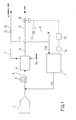
- Fig. 1 shows a block diagram of the method of the present invention;
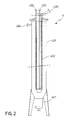
- Fig. 2 shows a sectional side view of the condensing means according to the invention;
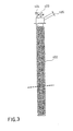
- Fig. 3 shows a view according to the same direction from Fig. 2 of the detail of the condensing means coil according to the invention.
- Fig. 1 shows the condensing step of the gases generated during the grinding step of the composite product and the briquetting step of the synthetic foamed material reclaimed during the recycling process, downstream of the initial grinding. These subsequent steps, being completely conventional, are not shown, as they are not a specific object of the present invention. It will be sufficient to add that the synthetic foamed material is reclaimed by suction from the composite material flow produced in the grinding step. This composite material, downstream of the grinding, is normally dispensed on suitable belt conveyers, from which one or more suction ports draw in the foamed material, being lighter than the other materials, and convey the latter to the briquetting machine.
- Both the grinding action inside the grinder and the foamed material compaction inside the briquetting machine release considerable amounts of gas from this material, i.e. the expansion gas used for preparing the material. This gas is a condensable polluting gas and is typically either a saturated hydrocarbon, particularly pentane, or a Freon, such as R11 or R12.
- In figure 1, the grinding means have been schematically indicated with
number 1 and the briquetting means have been indicated withnumber 2. - The usually employed grinding means 1 are equipments of a known type. The composite product, being preventively separated from parts containing toxicants/pollutants, such as (motor) oil or various nature gases such as the coolant gases (refrigerator or air-conditioner heat exchangers), is introduced into the mill, from which the composite material will flow out in ground form, in the desired size. The size may be changed by acting on the mill speed and grinding time and by placing a netting-screen with holes of the desired size at the mill exhaust opening.
- The briquetting means 2 are also of the conventional type and comprise pressing and extrusion means of the briquetted material.
- The gas released both from the grinding means 1 and the briquetting means 2 is drawn in by the intake means 3 (typically a fan), together with air, and conveyed to the condensing means 4, by means of a suitable pipeline 5.
- With reference to figure 2, the condensing means 4 comprise a
casing 401 inside which a double-coil heat exchanger 402 is placed, provided with inlet andoutlet apertures double coil 402. This coolant is an inert fluid with a boiling point lower than -130°C. Typically, this inert coolant is liquid nitrogen, therefore reference will be made to this coolant in the continuation of the present description, by way of example and in a non-limiting manner. The condensing means 1 further comprise aloading opening 405 for the condensable air/polluting gas mixture and an exhaust opening 406 for the fresh air. The particular geometry of the heat exchanger and the applied fluid dynamic conditions prevent a layer of solidified components from depositing on the heat exchange surfaces, thus avoiding the loss of efficiency and the risk that the system may be blocked due to a mechanical obstruction. This problem is deeply felt because the gaseous stream also carries high-melting substances such as oils and ammonium salts originating from the contamination of the refrigerator foamed materials with ammonia and lubricants of the cold production circuit. - The polluting gases, being in contact with the
coil 402 through which the liquid nitrogen flows, condense and are collected on the collectingbottom 407 of the condensing means, from which they are tapped and sent to the disposal. On the contrary, the fresh air flowing from the condensing means 4 is headed to the vent along theline 6. - On the other hand, the liquid nitrogen, after having absorbed heat, passes into the aeriform state and flows from the condensing means along the
line 7. Thisline 7 recycles the gaseous nitrogen within the grinding means 1. - The recycle line 8 of a portion of fresh air within the grinding means 1 branches from the
vent line 6 for the air. - Both the
vent line 6, downstream of the branch of the line 8, and the recycle line 8 for the air are intercepted by respective valve means 10, 11 which provide for the adjusting of the gas flow and hence the pressure inside the grinding means 1. - The
vent line 12 for the nitrogen, intercepted by the valve means 13, branches from therecycle line 7 for the nitrogen. - In standard operating conditions, the valve means 13 are closed, so that all the nitrogen flowing from the condensing means 4 is recycled in the grinding means 1. The introduction of an inert gas such as the nitrogen causes a substantially inert atmosphere within the grinding means, after the system has worked for few minutes. Thereby, it is avoided that the polluting hydrocarbon gases, optionally exhaled by the foamed material, may cause a burst, even in the presence of possible sparks.
- As said, a portion of the fresh air flowing from the condensing means 4 along the
lines lines 7 and 8 are such as to cause a substantially inert atmosphere within these grinding means 1, the amount of oxygen being lower than 5% by volume compared to the total volume of the aeriform substances. - Moreover, the cold and dry air and nitrogen flow lowers the moisture content in the internal atmosphere of the grinding means 1 and consequently in the gas flow entering the condensing means 4. Thereby, the liquid nitrogen consumption is minimized, because the consumption thereof due to the unnecessary steam condensation is reduced. In other words, the same nitrogen, which in the form of liquid nitrogen causes the condensing of the condensable polluting gases inside the condensing means 4, is used in the form of gas together with the recirculating air, in order to reduce the steam concentration in the grinding means 1. A further advantage is that the internal temperature is maintained at a completely safe value, both to the machined product and the system. This temperature is preferably lower than 50°C.
- It is important that a slight depression is always present inside the grinding means 1, in order to avoid that the generated gas may escape to the outside with imaginable environmental problems. Therefore, it can be recommended that some pressure sensors should be present within the grinding means 1 and that this internal pressure may be kept under control by means of a
suitable pressure indicator 14, such as to stop or at least reduce the entering nitrogen and/or air flow. This effect can be obtained either by partially or totally closing the valve means 11 and opening the valve means 10 and optionally acting on the valve means 13. - It is preferred that this operation is automatically controlled. To this purpose, in one preferred embodiment of the present invention, a control and
monitoring unit 15 is connected to saidpressure indicator 14 and is operatively connected to the valve means 10, 11 of thevent line 6 and the recycle line 8 for the air, respectively. The control andmonitoring unit 15 reads the pressure inside the grinding means 1 by means of thepressure indicator 14 and transmits a suitable closing control of the valve means 11 and/or an opening control of the valve means 10 if this pressure reaches a pre-determined level which is slightly lower than the atmospheric pressure. - From what has been stated above, the advantages of the present invention are immediately understood.
- The recycle of the nitrogen/air mixture allows both to avoid the risk of bursts during the grinding and to reduce the liquid nitrogen consumption in the condensing step. The recycle of cold nitrogen and air further allows the grinder internal temperature to be maintained at acceptable values, especially in the case of a 24-hour continuous processing.
- The control and monitoring unit allows to work in an extreme safety, thus avoiding that some overpressures which would cause the leakage of a part of the polluting gases may be produced in the grinding means.
- It is understood that only some particular embodiments of the method and equipment being the object of the present invention have been described, to which those skilled in the art will be able to carry out all the modifications required for the adjustment thereof to particular applications, without thus departing from the scope of protection of the present invention.
Claims (11)
- A method for recycling a composite product such as a refrigerator or the like, comprising a grinding step of said composite product in grinding means (1) for providing a composite material with generation of condensable polluting gases and a condensing step in condensing means (4) of said condensable polluting gases, wherein said condensing step is carried out by an inert coolant, characterized in that said inert coolant flowing from said condensing means (4) in the aeriform state is recycled in said grinding means (1).
- The recycling method according to claim 1, wherein said inert coolant has a boiling point which is lower than -130°C.
- The recycling method according to claim 2, wherein said inert coolant is liquid nitrogen.
- The recycling method according to any of the claims 1 to 3, wherein said grinding means (1) are depressurised by suction means (3) putting in flow communication said grinding means (1) with said condensing means (4).
- The recycling method according to any of the claims 1 to 4, wherein a portion of air flowing from said condensing means (4) is further added in said grinding means (1) after it is subject to the condensing treatment of said condensable polluting gases.
- The recycling method according to claim 5, wherein said air portion corresponds to 10-15% by volume of the air flowing from said condensing means (4).
- The recycling method according to claim 5 or 6, wherein said air flowing from said condensing means (4) is distributed between a vent line (6) and a recycle line (8), said vent and recycle (6, 8) lines being intercepted by respective valve means (10, 11).
- The recycling method according to any of the claims 5 to 7, wherein said grinding means (1) comprise pressure sensors connected to a pressure indicator (14).
- The recycling method according to any of the claims 4 to 8, wherein a control and monitoring unit (15) is provided, being connected to said pressure indicator (14) and operatively connected to said valve means (10, 11) of the vent line (6) and of the recycle line (8) for the air, respectively, wherein said control and monitoring unit (15) reads the pressure inside the grinding means (1) by means of the pressure indicator (14) and transmits a suitable closing control of the valve means (11) and/or an opening control of the valve means (10) if this pressure reaches a pre-determined level which is slightly lower than the atmospheric pressure.
- The recycling method according to any of the claims 1 to 9, wherein said condensing means (4) comprise a casing (401) inside which a double-coil heat exchanger (402) is placed, provided with inlet and outlet apertures (403, 404) for said inert coolant, said casing (401) further comprising a loading opening (405) for the condensable air/polluting gas mixture, an exhaust opening (406) for the fresh air and a collecting bottom (407) for said condensed polluting gases.
- Condensing means (4) such as defined in claim 11.
Priority Applications (5)
| Application Number | Priority Date | Filing Date | Title |
|---|---|---|---|
| EP20050425540 EP1747823B1 (en) | 2005-07-25 | 2005-07-25 | Condensing method for recycling systems |
| AT05425540T ATE396794T1 (en) | 2005-07-25 | 2005-07-25 | CONDENSATION PROCESS FOR RECYCLING SYSTEMS |
| DE200560007206 DE602005007206D1 (en) | 2005-07-25 | 2005-07-25 | Condensation process for recycling systems |
| RU2006126902A RU2396132C2 (en) | 2005-07-25 | 2006-07-24 | Method and equipment for condensation, for retreatment systems |
| CNA2006101034852A CN1903406A (en) | 2005-07-25 | 2006-07-25 | Condensing method and equipment for recycling systems |
Applications Claiming Priority (1)
| Application Number | Priority Date | Filing Date | Title |
|---|---|---|---|
| EP20050425540 EP1747823B1 (en) | 2005-07-25 | 2005-07-25 | Condensing method for recycling systems |
Publications (2)
| Publication Number | Publication Date |
|---|---|
| EP1747823A1 true EP1747823A1 (en) | 2007-01-31 |
| EP1747823B1 EP1747823B1 (en) | 2008-05-28 |
Family
ID=35539154
Family Applications (1)
| Application Number | Title | Priority Date | Filing Date |
|---|---|---|---|
| EP20050425540 Expired - Lifetime EP1747823B1 (en) | 2005-07-25 | 2005-07-25 | Condensing method for recycling systems |
Country Status (5)
| Country | Link |
|---|---|
| EP (1) | EP1747823B1 (en) |
| CN (1) | CN1903406A (en) |
| AT (1) | ATE396794T1 (en) |
| DE (1) | DE602005007206D1 (en) |
| RU (1) | RU2396132C2 (en) |
Cited By (2)
| Publication number | Priority date | Publication date | Assignee | Title |
|---|---|---|---|---|
| EP2399719A1 (en) | 2010-06-23 | 2011-12-28 | Total Petrochemicals Research Feluy | Method to recover polystyrene from recycled refrigerators |
| WO2025027149A1 (en) | 2023-08-03 | 2025-02-06 | Ineos Styrolution Group Gmbh | Recyclable vinylaromatic polymer composite article and process for producing the same |
Families Citing this family (3)
| Publication number | Priority date | Publication date | Assignee | Title |
|---|---|---|---|---|
| DE102010030544A1 (en) * | 2010-06-25 | 2011-12-29 | Bhs-Sonthofen Gmbh | Method and device for crushing refrigerators |
| RU2483814C1 (en) * | 2012-05-15 | 2013-06-10 | Федеральное государственное бюджетное образовательное учреждение высшего профессионального образования "Московский государственный университет инженерной экологии" (ФГБОУ ВПО "МГУИЭ") | Method of disposal of solid toxic ashy wastes from incinerator plant filters |
| CN108380350A (en) * | 2018-02-08 | 2018-08-10 | 西南科技大学 | The closed cycle drug processing technology and device of no isopropanol discharge |
Citations (4)
| Publication number | Priority date | Publication date | Assignee | Title |
|---|---|---|---|---|
| EP1149862A1 (en) * | 2000-04-28 | 2001-10-31 | Matsushita Refrigeration Company | Method of recycling rigid polyurethane foam |
| WO2002002209A2 (en) * | 2000-06-30 | 2002-01-10 | Owens Corning | Recovery of blowing agent from polymeric foam |
| GB2383761A (en) * | 2002-01-04 | 2003-07-09 | Anthony James Clark | Process for the removal of blowing agents / ozone depleting substances from rigid foam in refrigeration equipment |
| EP1473071A1 (en) * | 2003-04-30 | 2004-11-03 | Air Products And Chemicals, Inc. | Method and system for purifying exhaust gas |
Family Cites Families (2)
| Publication number | Priority date | Publication date | Assignee | Title |
|---|---|---|---|---|
| SU1556745A1 (en) * | 1988-01-20 | 1990-04-15 | Днепропетровский Металлургический Институт | Arrangement for disintegrating plates from composite materials on polymer base |
| DE19654255B4 (en) * | 1996-12-23 | 2007-08-30 | Herhof Verwaltungsgesellschaft Mbh | Method and device for treating waste or residual waste |
-
2005
- 2005-07-25 AT AT05425540T patent/ATE396794T1/en not_active IP Right Cessation
- 2005-07-25 DE DE200560007206 patent/DE602005007206D1/en not_active Expired - Lifetime
- 2005-07-25 EP EP20050425540 patent/EP1747823B1/en not_active Expired - Lifetime
-
2006
- 2006-07-24 RU RU2006126902A patent/RU2396132C2/en not_active IP Right Cessation
- 2006-07-25 CN CNA2006101034852A patent/CN1903406A/en active Pending
Patent Citations (4)
| Publication number | Priority date | Publication date | Assignee | Title |
|---|---|---|---|---|
| EP1149862A1 (en) * | 2000-04-28 | 2001-10-31 | Matsushita Refrigeration Company | Method of recycling rigid polyurethane foam |
| WO2002002209A2 (en) * | 2000-06-30 | 2002-01-10 | Owens Corning | Recovery of blowing agent from polymeric foam |
| GB2383761A (en) * | 2002-01-04 | 2003-07-09 | Anthony James Clark | Process for the removal of blowing agents / ozone depleting substances from rigid foam in refrigeration equipment |
| EP1473071A1 (en) * | 2003-04-30 | 2004-11-03 | Air Products And Chemicals, Inc. | Method and system for purifying exhaust gas |
Cited By (2)
| Publication number | Priority date | Publication date | Assignee | Title |
|---|---|---|---|---|
| EP2399719A1 (en) | 2010-06-23 | 2011-12-28 | Total Petrochemicals Research Feluy | Method to recover polystyrene from recycled refrigerators |
| WO2025027149A1 (en) | 2023-08-03 | 2025-02-06 | Ineos Styrolution Group Gmbh | Recyclable vinylaromatic polymer composite article and process for producing the same |
Also Published As
| Publication number | Publication date |
|---|---|
| RU2006126902A (en) | 2008-01-27 |
| DE602005007206D1 (en) | 2008-07-10 |
| EP1747823B1 (en) | 2008-05-28 |
| CN1903406A (en) | 2007-01-31 |
| RU2396132C2 (en) | 2010-08-10 |
| ATE396794T1 (en) | 2008-06-15 |
Similar Documents
| Publication | Publication Date | Title |
|---|---|---|
| US5645382A (en) | Controlled atmosphere machining | |
| US5302300A (en) | Method and apparatus for separating water from a condensate mixture in a compressed air system | |
| WO1989009663A1 (en) | Arrangement for eliminating foaming and/or cooling agents | |
| US9770704B2 (en) | Method and device for removing dust and cooling for active coke regeneration apparatus | |
| EP1747823B1 (en) | Condensing method for recycling systems | |
| US11320184B2 (en) | HVACR system using environmentally-friendly refrigerant with purge | |
| AU660280B2 (en) | Method and apparatus for reclaiming a refrigerant | |
| CN100574907C (en) | A system and method for recycling waste electric appliances | |
| RU135015U1 (en) | COMPRESSOR STATION TRANSPORTABLE | |
| CN1985135A (en) | Oil separator for compressor of vapor compression system | |
| US6158234A (en) | Self-cooled refrigerant recovery system | |
| NL8902158A (en) | DEVICE FOR DRAINING FLUIDUM THROUGH A WALL. | |
| CN108672799A (en) | A kind of cutter device for the processing of automobile pipe fitting | |
| JP5744125B2 (en) | Method and apparatus to withstand disabling of compressors in a multi-stage compression system | |
| CN206578344U (en) | A kind of cutter device processed for automobile pipe fitting | |
| JP4007847B2 (en) | Deterioration product recovery and deodorization equipment in vacuum heating equipment | |
| EP2049695B1 (en) | System for creating a vacuum in a tanning dryer | |
| KR20080051253A (en) | Odor gas removal system and method of food waste disposal device | |
| RU2219445C2 (en) | Ammonia cooling machine | |
| CN114439735B (en) | A method for monitoring safe operation of a catalytic oil-free compression system | |
| GB2138553A (en) | Apparatus for conditioning compressed gas | |
| CN221452887U (en) | Air pretreatment system of crushing system | |
| CN218404343U (en) | A cooling device for transmission gear processing | |
| CN102901288A (en) | Recycling method for chloro flouro carbon (CFC) in refrigeration device | |
| JPH07208773A (en) | Ground air conditioner for air plane having high pressure air supplying system |
Legal Events
| Date | Code | Title | Description |
|---|---|---|---|
| PUAI | Public reference made under article 153(3) epc to a published international application that has entered the european phase |
Free format text: ORIGINAL CODE: 0009012 |
|
| AK | Designated contracting states |
Kind code of ref document: A1 Designated state(s): AT BE BG CH CY CZ DE DK EE ES FI FR GB GR HU IE IS IT LI LT LU LV MC NL PL PT RO SE SI SK TR |
|
| AX | Request for extension of the european patent |
Extension state: AL BA HR MK YU |
|
| 17P | Request for examination filed |
Effective date: 20070618 |
|
| 17Q | First examination report despatched |
Effective date: 20070726 |
|
| AKX | Designation fees paid |
Designated state(s): AT BE BG CH CY CZ DE DK EE ES FI FR GB GR HU IE IS IT LI LT LU LV MC NL PL PT RO SE SI SK TR |
|
| AXX | Extension fees paid |
Extension state: MK Payment date: 20070618 Extension state: HR Payment date: 20070618 Extension state: YU Payment date: 20070618 Extension state: AL Payment date: 20070618 Extension state: BA Payment date: 20070618 |
|
| GRAP | Despatch of communication of intention to grant a patent |
Free format text: ORIGINAL CODE: EPIDOSNIGR1 |
|
| RTI1 | Title (correction) |
Free format text: CONDENSING METHOD FOR RECYCLING SYSTEMS |
|
| GRAS | Grant fee paid |
Free format text: ORIGINAL CODE: EPIDOSNIGR3 |
|
| GRAA | (expected) grant |
Free format text: ORIGINAL CODE: 0009210 |
|
| AK | Designated contracting states |
Kind code of ref document: B1 Designated state(s): AT BE BG CH CY CZ DE DK EE ES FI FR GB GR HU IE IS IT LI LT LU LV MC NL PL PT RO SE SI SK TR |
|
| AX | Request for extension of the european patent |
Extension state: AL BA HR MK YU |
|
| REG | Reference to a national code |
Ref country code: GB Ref legal event code: FG4D |
|
| REG | Reference to a national code |
Ref country code: CH Ref legal event code: EP |
|
| REF | Corresponds to: |
Ref document number: 602005007206 Country of ref document: DE Date of ref document: 20080710 Kind code of ref document: P |
|
| REG | Reference to a national code |
Ref country code: IE Ref legal event code: FG4D |
|
| PG25 | Lapsed in a contracting state [announced via postgrant information from national office to epo] |
Ref country code: SI Free format text: LAPSE BECAUSE OF FAILURE TO SUBMIT A TRANSLATION OF THE DESCRIPTION OR TO PAY THE FEE WITHIN THE PRESCRIBED TIME-LIMIT Effective date: 20080528 |
|
| PG25 | Lapsed in a contracting state [announced via postgrant information from national office to epo] |
Ref country code: ES Free format text: LAPSE BECAUSE OF FAILURE TO SUBMIT A TRANSLATION OF THE DESCRIPTION OR TO PAY THE FEE WITHIN THE PRESCRIBED TIME-LIMIT Effective date: 20080908 Ref country code: FI Free format text: LAPSE BECAUSE OF FAILURE TO SUBMIT A TRANSLATION OF THE DESCRIPTION OR TO PAY THE FEE WITHIN THE PRESCRIBED TIME-LIMIT Effective date: 20080528 |
|
| PG25 | Lapsed in a contracting state [announced via postgrant information from national office to epo] |
Ref country code: NL Free format text: LAPSE BECAUSE OF FAILURE TO SUBMIT A TRANSLATION OF THE DESCRIPTION OR TO PAY THE FEE WITHIN THE PRESCRIBED TIME-LIMIT Effective date: 20080528 Ref country code: LV Free format text: LAPSE BECAUSE OF FAILURE TO SUBMIT A TRANSLATION OF THE DESCRIPTION OR TO PAY THE FEE WITHIN THE PRESCRIBED TIME-LIMIT Effective date: 20080528 Ref country code: AT Free format text: LAPSE BECAUSE OF FAILURE TO SUBMIT A TRANSLATION OF THE DESCRIPTION OR TO PAY THE FEE WITHIN THE PRESCRIBED TIME-LIMIT Effective date: 20080528 |
|
| NLV1 | Nl: lapsed or annulled due to failure to fulfill the requirements of art. 29p and 29m of the patents act | ||
| PG25 | Lapsed in a contracting state [announced via postgrant information from national office to epo] |
Ref country code: IS Free format text: LAPSE BECAUSE OF FAILURE TO SUBMIT A TRANSLATION OF THE DESCRIPTION OR TO PAY THE FEE WITHIN THE PRESCRIBED TIME-LIMIT Effective date: 20080928 |
|
| PG25 | Lapsed in a contracting state [announced via postgrant information from national office to epo] |
Ref country code: LT Free format text: LAPSE BECAUSE OF FAILURE TO SUBMIT A TRANSLATION OF THE DESCRIPTION OR TO PAY THE FEE WITHIN THE PRESCRIBED TIME-LIMIT Effective date: 20080528 Ref country code: CZ Free format text: LAPSE BECAUSE OF FAILURE TO SUBMIT A TRANSLATION OF THE DESCRIPTION OR TO PAY THE FEE WITHIN THE PRESCRIBED TIME-LIMIT Effective date: 20080528 Ref country code: SE Free format text: LAPSE BECAUSE OF FAILURE TO SUBMIT A TRANSLATION OF THE DESCRIPTION OR TO PAY THE FEE WITHIN THE PRESCRIBED TIME-LIMIT Effective date: 20080828 Ref country code: DK Free format text: LAPSE BECAUSE OF FAILURE TO SUBMIT A TRANSLATION OF THE DESCRIPTION OR TO PAY THE FEE WITHIN THE PRESCRIBED TIME-LIMIT Effective date: 20080528 |
|
| PG25 | Lapsed in a contracting state [announced via postgrant information from national office to epo] |
Ref country code: RO Free format text: LAPSE BECAUSE OF FAILURE TO SUBMIT A TRANSLATION OF THE DESCRIPTION OR TO PAY THE FEE WITHIN THE PRESCRIBED TIME-LIMIT Effective date: 20080528 Ref country code: SK Free format text: LAPSE BECAUSE OF FAILURE TO SUBMIT A TRANSLATION OF THE DESCRIPTION OR TO PAY THE FEE WITHIN THE PRESCRIBED TIME-LIMIT Effective date: 20080528 Ref country code: PT Free format text: LAPSE BECAUSE OF FAILURE TO SUBMIT A TRANSLATION OF THE DESCRIPTION OR TO PAY THE FEE WITHIN THE PRESCRIBED TIME-LIMIT Effective date: 20081028 Ref country code: BE Free format text: LAPSE BECAUSE OF FAILURE TO SUBMIT A TRANSLATION OF THE DESCRIPTION OR TO PAY THE FEE WITHIN THE PRESCRIBED TIME-LIMIT Effective date: 20080528 |
|
| PG25 | Lapsed in a contracting state [announced via postgrant information from national office to epo] |
Ref country code: MC Free format text: LAPSE BECAUSE OF NON-PAYMENT OF DUE FEES Effective date: 20080731 |
|
| PLBE | No opposition filed within time limit |
Free format text: ORIGINAL CODE: 0009261 |
|
| STAA | Information on the status of an ep patent application or granted ep patent |
Free format text: STATUS: NO OPPOSITION FILED WITHIN TIME LIMIT |
|
| PG25 | Lapsed in a contracting state [announced via postgrant information from national office to epo] |
Ref country code: EE Free format text: LAPSE BECAUSE OF FAILURE TO SUBMIT A TRANSLATION OF THE DESCRIPTION OR TO PAY THE FEE WITHIN THE PRESCRIBED TIME-LIMIT Effective date: 20080528 Ref country code: BG Free format text: LAPSE BECAUSE OF FAILURE TO SUBMIT A TRANSLATION OF THE DESCRIPTION OR TO PAY THE FEE WITHIN THE PRESCRIBED TIME-LIMIT Effective date: 20080828 |
|
| 26N | No opposition filed |
Effective date: 20090303 |
|
| PG25 | Lapsed in a contracting state [announced via postgrant information from national office to epo] |
Ref country code: IE Free format text: LAPSE BECAUSE OF NON-PAYMENT OF DUE FEES Effective date: 20080725 |
|
| REG | Reference to a national code |
Ref country code: CH Ref legal event code: PL |
|
| GBPC | Gb: european patent ceased through non-payment of renewal fee |
Effective date: 20090725 |
|
| PG25 | Lapsed in a contracting state [announced via postgrant information from national office to epo] |
Ref country code: LI Free format text: LAPSE BECAUSE OF NON-PAYMENT OF DUE FEES Effective date: 20090731 Ref country code: CH Free format text: LAPSE BECAUSE OF NON-PAYMENT OF DUE FEES Effective date: 20090731 |
|
| PG25 | Lapsed in a contracting state [announced via postgrant information from national office to epo] |
Ref country code: PL Free format text: LAPSE BECAUSE OF FAILURE TO SUBMIT A TRANSLATION OF THE DESCRIPTION OR TO PAY THE FEE WITHIN THE PRESCRIBED TIME-LIMIT Effective date: 20080528 Ref country code: GB Free format text: LAPSE BECAUSE OF NON-PAYMENT OF DUE FEES Effective date: 20090725 |
|
| PG25 | Lapsed in a contracting state [announced via postgrant information from national office to epo] |
Ref country code: LU Free format text: LAPSE BECAUSE OF NON-PAYMENT OF DUE FEES Effective date: 20080725 Ref country code: HU Free format text: LAPSE BECAUSE OF FAILURE TO SUBMIT A TRANSLATION OF THE DESCRIPTION OR TO PAY THE FEE WITHIN THE PRESCRIBED TIME-LIMIT Effective date: 20081129 Ref country code: CY Free format text: LAPSE BECAUSE OF FAILURE TO SUBMIT A TRANSLATION OF THE DESCRIPTION OR TO PAY THE FEE WITHIN THE PRESCRIBED TIME-LIMIT Effective date: 20080528 |
|
| PG25 | Lapsed in a contracting state [announced via postgrant information from national office to epo] |
Ref country code: TR Free format text: LAPSE BECAUSE OF FAILURE TO SUBMIT A TRANSLATION OF THE DESCRIPTION OR TO PAY THE FEE WITHIN THE PRESCRIBED TIME-LIMIT Effective date: 20080528 |
|
| PG25 | Lapsed in a contracting state [announced via postgrant information from national office to epo] |
Ref country code: GR Free format text: LAPSE BECAUSE OF FAILURE TO SUBMIT A TRANSLATION OF THE DESCRIPTION OR TO PAY THE FEE WITHIN THE PRESCRIBED TIME-LIMIT Effective date: 20080829 |
|
| PGFP | Annual fee paid to national office [announced via postgrant information from national office to epo] |
Ref country code: DE Payment date: 20100723 Year of fee payment: 6 Ref country code: FR Payment date: 20100823 Year of fee payment: 6 Ref country code: IT Payment date: 20100717 Year of fee payment: 6 |
|
| REG | Reference to a national code |
Ref country code: FR Ref legal event code: ST Effective date: 20120330 |
|
| PG25 | Lapsed in a contracting state [announced via postgrant information from national office to epo] |
Ref country code: DE Free format text: LAPSE BECAUSE OF NON-PAYMENT OF DUE FEES Effective date: 20120201 Ref country code: FR Free format text: LAPSE BECAUSE OF NON-PAYMENT OF DUE FEES Effective date: 20110801 |
|
| REG | Reference to a national code |
Ref country code: DE Ref legal event code: R119 Ref document number: 602005007206 Country of ref document: DE Effective date: 20120201 |
|
| PG25 | Lapsed in a contracting state [announced via postgrant information from national office to epo] |
Ref country code: IT Free format text: LAPSE BECAUSE OF NON-PAYMENT OF DUE FEES Effective date: 20110725 |