EP1747701B1 - Induction furnace for melting granular materials - Google Patents
Induction furnace for melting granular materials Download PDFInfo
- Publication number
- EP1747701B1 EP1747701B1 EP05747594.9A EP05747594A EP1747701B1 EP 1747701 B1 EP1747701 B1 EP 1747701B1 EP 05747594 A EP05747594 A EP 05747594A EP 1747701 B1 EP1747701 B1 EP 1747701B1
- Authority
- EP
- European Patent Office
- Prior art keywords
- crucible
- melting
- melting cavity
- conductive
- conductive circuit
- Prior art date
- Legal status (The legal status is an assumption and is not a legal conclusion. Google has not performed a legal analysis and makes no representation as to the accuracy of the status listed.)
- Active
Links
- 238000002844 melting Methods 0.000 title claims description 206
- 230000008018 melting Effects 0.000 title claims description 205
- 230000006698 induction Effects 0.000 title claims description 93
- 239000008187 granular material Substances 0.000 title 1
- 239000000463 material Substances 0.000 claims description 131
- 239000012768 molten material Substances 0.000 claims description 100
- 238000010438 heat treatment Methods 0.000 claims description 85
- 230000001939 inductive effect Effects 0.000 claims description 48
- 230000005672 electromagnetic field Effects 0.000 claims description 24
- 238000000034 method Methods 0.000 claims description 21
- 230000007246 mechanism Effects 0.000 claims description 20
- 238000004891 communication Methods 0.000 claims description 17
- 239000004065 semiconductor Substances 0.000 claims description 17
- 238000012546 transfer Methods 0.000 claims description 17
- 239000013078 crystal Substances 0.000 claims description 12
- 239000002245 particle Substances 0.000 claims description 10
- 239000007787 solid Substances 0.000 claims description 8
- 230000005674 electromagnetic induction Effects 0.000 claims description 7
- 230000015572 biosynthetic process Effects 0.000 claims description 6
- 230000005855 radiation Effects 0.000 claims description 5
- 238000013021 overheating Methods 0.000 claims description 4
- 239000002994 raw material Substances 0.000 description 54
- 239000007788 liquid Substances 0.000 description 12
- 239000000155 melt Substances 0.000 description 10
- 238000010309 melting process Methods 0.000 description 10
- OKTJSMMVPCPJKN-UHFFFAOYSA-N Carbon Chemical class [C] OKTJSMMVPCPJKN-UHFFFAOYSA-N 0.000 description 8
- 229910052799 carbon Inorganic materials 0.000 description 5
- 230000007423 decrease Effects 0.000 description 5
- 239000011236 particulate material Substances 0.000 description 5
- 230000002028 premature Effects 0.000 description 5
- 239000010453 quartz Substances 0.000 description 5
- VYPSYNLAJGMNEJ-UHFFFAOYSA-N silicon dioxide Inorganic materials O=[Si]=O VYPSYNLAJGMNEJ-UHFFFAOYSA-N 0.000 description 5
- 229910002804 graphite Chemical class 0.000 description 4
- 239000010439 graphite Chemical class 0.000 description 4
- 230000001965 increasing effect Effects 0.000 description 4
- 238000007792 addition Methods 0.000 description 3
- 239000012535 impurity Substances 0.000 description 3
- 230000005499 meniscus Effects 0.000 description 3
- 230000008878 coupling Effects 0.000 description 2
- 238000010168 coupling process Methods 0.000 description 2
- 238000005859 coupling reaction Methods 0.000 description 2
- 230000000694 effects Effects 0.000 description 2
- 230000006872 improvement Effects 0.000 description 2
- 238000004519 manufacturing process Methods 0.000 description 2
- 239000011819 refractory material Substances 0.000 description 2
- 230000009471 action Effects 0.000 description 1
- 230000008901 benefit Effects 0.000 description 1
- 150000001721 carbon Chemical class 0.000 description 1
- 239000000919 ceramic Substances 0.000 description 1
- 230000008859 change Effects 0.000 description 1
- 239000004020 conductor Substances 0.000 description 1
- 238000012937 correction Methods 0.000 description 1
- 230000003247 decreasing effect Effects 0.000 description 1
- 230000008034 disappearance Effects 0.000 description 1
- 239000002657 fibrous material Substances 0.000 description 1
- 238000007667 floating Methods 0.000 description 1
- 230000008014 freezing Effects 0.000 description 1
- 238000007710 freezing Methods 0.000 description 1
- 239000000289 melt material Substances 0.000 description 1
- 239000002184 metal Substances 0.000 description 1
- 230000035515 penetration Effects 0.000 description 1
- 230000008569 process Effects 0.000 description 1
- 238000007670 refining Methods 0.000 description 1
- 230000000284 resting effect Effects 0.000 description 1
- 230000000007 visual effect Effects 0.000 description 1
- 238000004857 zone melting Methods 0.000 description 1
Images


Classifications
-
- H—ELECTRICITY
- H05—ELECTRIC TECHNIQUES NOT OTHERWISE PROVIDED FOR
- H05B—ELECTRIC HEATING; ELECTRIC LIGHT SOURCES NOT OTHERWISE PROVIDED FOR; CIRCUIT ARRANGEMENTS FOR ELECTRIC LIGHT SOURCES, IN GENERAL
- H05B6/00—Heating by electric, magnetic or electromagnetic fields
- H05B6/02—Induction heating
- H05B6/22—Furnaces without an endless core
- H05B6/24—Crucible furnaces
Definitions
- the invention relates to induction heating and an improved induction furnace. More particularly, the invention relates to an induction furnace for melting materials not susceptible to inductive heating at lower temperatures but which are susceptible to inductive heating at higher temperatures, especially upon melting. Specifically, the invention relates to an induction furnace capable of continuously or intermittently melting such materials.
- Induction furnaces are well known in the art. However, there are a variety of difficulties related to the inductive heating and melting of materials that are initially non-conductive or which have particle sizes sufficiently small so that they are not susceptible to inductive heating.
- Many prior art induction furnaces utilize a conductive crucible such that an induction coil couples with the crucible to transfer energy directly to the crucible to heat the crucible whereby heat is then transferred from the crucible to the material to be melted via thermal conduction.
- the induction frequency and the thickness of the crucible wall may be selected so that a portion of the electromagnetic field from the coil allows coupling with electrically conductive material inside the crucible to inductively heat the material directly.
- the direct inductive heating in such cases is quite limited. Because direct inductive heating of the material to be melted is far more effective than the method described above, a system to effect such direct inductive heating is highly desirable.
- the conductive crucibles of the prior art may react with the material to be melted which causes unwanted impurities in the melt and thus requires the use of a non-reactive liner inside the crucible to prevent formation of such impurities.
- liners are electrically non-conductive and thermally insulating.
- the transfer of heat from the crucible to the materials to be melted is greatly impeded and thus melting times are substantially increased.
- the crucible must be heated to undesirably high temperatures which can decrease the life of the crucible and liner.
- An induction furnace capable of producing a continuous melt in an efficient manner, especially for semi-conductor materials.
- An efficient continuous melt induction furnace is particularly useful related to continuous formation of semi-conductor crystals, which are highly valued in the production of computer chips.
- the first two embodiments of Takase et al. involve the use of a carbon cylinder susceptor which encircles the quartz crucible and is movable in a vertical direction. This provides a mechanism whereby the susceptor may bye inductively heated and then either moved out of the electromagnetic field of the induction coil altogether or moved to a position which is more advantageous for heating selected portions of the material within the crucible.
- One drawback of this configuration is the need for a mechanism to move the susceptor in a vertical direction.
- the susceptor has a crucible-like configuration with a cylindrical side wall of the susceptor covering the side wall of the quartz crucible and a bottom of the susceptor covering the bottom wall of the quartz crucible.
- the susceptor is not vertically moveable in the third embodiment. Instead, the thickness of the susceptor sidewall and the frequency applied by the coil are selected so that the penetration depth of the induction current will extend beyond the susceptor into the quartz crucible so that it can inductively heat material inside.
- the third embodiment of Takase et al. primarily suffers from the fact that the cylindrical susceptor remains in place and thus prevents inductive heating from more effectively being focused on the raw material within the crucible. Instead, the coil continues to inductively heat the carbon cylinder so that energy which might be applied to the material is absorbed by the carbon cylinder, which transfers heat to the raw material in the crucible in a far less effective manner.
- DE2637939 discusses one of the problems with this method, for instance electrical discharges or flash-overs between the induction coil and the directly inductively semiconductor rod or other parts of the apparatus. It was known to disconnect the HF generator or AC electric source immediately when a flash-over occurs to avoid damaging the arrangement. However, this prior art practice made the rod unusable. It is disclosed to automatically disconnect the energy supply to the induction heating coil immediately if a flash-over occurs arid then automatically reconnect the energy supply to the induction coil. BRIEF SUMMARY
- the present invention provides an apparatus for heating a material, the apparatus comprising an electromagnetic induction member; an electrically conductive member selectively switchable between a closed electrical circuit and an open electrical circuit whereby the conductive member is inductively heatable by the induction member via the closed electrical circuit and whereby when the conductive memberforms the open electrical circuit, inductive heating of the conductive member by the induction member which would occur if the conductive member formed the closed electrical circuit is eliminated; and the conductive member being adapted to transfer heat to the material.
- the present invention also provides a method of heating material comprising the steps of: heating an electrically conductive member inductively with an electromagnetic induction member when the conductive member is in a closed electrical circuit mode; transferring heat from the conductive member to the material; and switching the conductive member to an open circuit mode to prevent further inductive heating of the conductive member which would occur if the conductive member remained in the closed circuit mode.
- the present invention further provides an apparatus for heating a material, the apparatus comprising an electrically conductive member selectively switchable between a closed electrical circuit mode and an open electrical circuit mode; the conductive member being resistively heatable when in the closed circuit mode and not being resistively heatable when in the open circuit mode; the conductive member being adapted to transfer heat to the material; and an electromagnetic induction member adapted to inductively heat the material.
- the present invention also provides a method of heating material comprising the steps of heating an electrically conductive member resistively when the conductive member is in a closed electrical circuit mode; transferring heat from the conductive member to the material; heating the material inductively with an electromagnetic induction member; and switching the conductive memberto an open circuit mode to prevents inductive heating of the conductive member which would occur if the conductive member remained in the closed circuit mode.
- the present invention further provides an apparatus comprising a crucible defining a melting cavity; an electromagnetic induction member for inductively heating molten material within the melting cavity; and a flow guide disposed within the melting cavity for directing the inductively heated molten material to flow upwardly within the cavity.
- the present invention also provides an apparatus comprising a crucible defining a melting cavity and an exit opening; and a trap defining a through passage having an entrance end defining an opening in communication with the melting cavity and an exit end defining an opening in communication with the exit opening of the crucible for transporting molten material from the melting cavity to the exit operning of the crucible whereby the relative pressure exerted on molten material in the passage controls the flow of molten material through the exit opening.
- the improved induction furnace of the present invention is shown in four embodiments in the figures although other embodiments are contemplated as is apparent to one of skill in the art.
- the first embodiment of the induction furnace is indicated generally at 100, and is shown in Figs. 1-3
- the second embodiment is indicated generally at 200, and is shown in Figs. 8-9
- the third embodiment is indicated generally at 300, and is shown in Figs. 16-17
- the fourth embodiment is indicated generally at 400, and is shown in Fig. 22 .
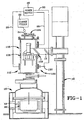
- furnace 100 is mounted on a support stand 10 via a support arm 12 extending therefrom, although furnace 100 may be supported by any suitable means.
- Furnace 100 is disposed above and connected to a standard crystal formation apparatus 16 which contains an interior chamber 18 in which is disposed a receiving crucible or tundish 20.
- a charge feeder 22 situated above furnace 100 is in communication with a feed port 24 whereby raw material may be fed into furnace 100.
- a power supply 26 is in electrical communication via wires 28 with a preheating induction coil 102 and a melting induction coil 104. Power supply 26 may also be in electrical communication via wires 30 with a melting coil 130.
- a double-walled heating container 106 defines an interior chamber 108 which is divided into a preheat zone 110 and a melting zone 112 there below.
- a preheating assembly 114 is disposed within preheat zone 110 and includes a cylindrical susceptor 116 disposed within preheating induction coil 102 and a preheat tube 118 disposed within susceptor 116 and closely adjacent or in abutment with susceptor 116.
- Preheat tube 118 defines an interior chamber 120 for receiving raw material 122 from feed port 24 for preheating the raw material.
- a feed mechanism 124 includes a control arm 126 with a valve 128 at the terminal end thereof. Valve 128 is selectively seated in exit opening 129 formed in the lower end of preheat tube 118.
- Furnace 100 further defines a quiescent zone 131 below preheat assembly 114, as detailed further below.
- substantially cylindrical melting coil 130 which acts as a susceptor, is disposed within melting induction coil 104 and is switchable between a closed electrical circuit mode and an open electrical circuit mode via switch 132.
- a melting crucible 134 is disposed within melting coil 130 and in combination with melting induction coil 104 and melting coil 130, forms a melting assembly 136.
- Melting coil 130 may provide lateral support for crucible 134.
- Melting crucible 134 includes a substantially cylindrical side wall 138 extending upwardly from a substantially flat bottom wall 140 which defines an exit opening 142 through which the flow of molten material is controlled by any suitable mechanism known in the art. Melting crucible 134 defines a melting cavity 146 in communication with exit opening 142 of bottom wall 140 as well as exit opening 129 of tube 118. In addition, a laser sight port 148 is in visual communication with melting cavity 146.
- furnace 100 functions as follows. Referring to Figs. 1-3 , raw material 122 is fed via charge feeder 22 into feed port 24 and subsequently into interior chamber 120 of preheating tube 118. Valve 128 (an angle of repose valve) is initially in a closed position ( Fig. 3 ) to prevent raw material 122 from passing through exit hole 129. Power supply 26 is then operated to provide electrical power through wires 28 to preheating induction coil 102. Induction coil 102 thus produces an electromagnetic field so that coil 102 couples with susceptor 116 to inductively heat susceptor 116. In turn, susceptor 116 transfers heat to raw material 122 through preheating tube 118 via conduction and radiation.
- Valve 128 an angle of repose valve
- Raw material 122 is thus heated to a point below the melting temperature of the material prior to charging crucible 134.
- Raw material 122 is typically granular, powdered or of another particulate form.
- feed mechanism 124 is operated to open valve 128 whereby a portion of material 122 is released into melting cavity 146 of crucible 134, as shown in Fig. 4 .
- Feed mechanism 124 is configured to control the rate at which material 122 falls into melting cavity 146.
- power supply 26 provides electrical power to melting induction coil 104 which creates an electromagnetic field so that induction coil 104 couples with melting coil 130 to inductively heat melting coil 130.
- Inductive heating of melting coil 130 occurs when switch 132 is closed and melting coil 130 thereby forms a closed electrical circuit whereby melting coil 130 is thus initially operated in a closed electrical circuit mode.
- melting coil 130 transfers heat to raw material 122 in melting cavity 146 of crucible 134 predominantly through side wall 138 of crucible 134. As shown in Fig. 5 , an initial portion of raw material 122 has melted, the molten portion indicated at 150.
- molten material 150 will include a cylindrical portion which flows down to form a pool portion.
- the cylindrical portion along side wall 138 provides a greater surface area of susceptible material in comparison to the pool portion, so that direct inductive heating of material 150 is enhanced thereby ( Figs. 5-6 ).
- Anotherfeature of the present invention is heating melting coil 130 resistively, either in combination with the inductive heating or as the sole source of heating melting coil 130.
- power supply 26 provides electrical power to melting coil 130 via wires 30 while melting coil 130 forms a closed electrical circuit.
- the heating of material 122 thereby is continued until a portion of material 122 becomes susceptible to inductive heating.
- switch 132 is opened so that melting coil 130 is in an open electrical circuit mode whereby inductive heating of melting coil 130 by induction coil 104 is predominantly eliminated. More particularly, when melting coil 130 is in the open electrical circuit mode or forms an open electrical circuit, inductive heating of melting coil 130 by induction coil 104 which would occur if melting coil 130 were in the closed electrical circuit mode is eliminated. If melting coil 130 is heated solely by resistance or by resistance in combination with inductive heating by induction coil 104, opening the closed circuit of melting coil 130 also terminates resistive heating.
- melting coil 130 has largely “disappeared” to induction coil 104, absorbing very little further energy from the electromagnetic field produced by induction coil 104, as discussed further below.
- induction coil 104 couples with the susceptible molten material 150 to directly inductively heat molten portion 150.
- This direct inductive heating of the susceptible material 150 permits heat to be transferred from molten portion 150 to solid raw material 122 to continue to melt material whereby the additional molten material also becomes susceptible to inductive heating.
- the "disappearance" of melting coil 130 to inductive heating decreases the heat imparted to crucible 134, which tends to extend the life of crucible 134.
- Fig. 5 also shows the continued addition of raw material 122 after melting has begun.
- Furnace 100 is configured to add raw material 122 as desired. It is often desirable to continuously or intermittently add raw material 122 throughout the melting process to provide continuous or intermittent melting and transfer of molten material 150 out of crucible 134. However, raw material 122 may simply be added in a batch form and melted in its entirety without further additions.
- Fig. 6 shows a further stage of melting with switch 132 in the open position whereby melting coil 130 has "disappeared" to coil 104, as noted above.
- Melting of raw material 122 proceeds via direct inductive heating of molten material 150 until all the material within melting cavity 146 is molten, as shown in Fig. 7 .
- Switch 132 remains in the open position, as the inductive heating of melting coil 130 is not needed or desired after initial molten portion 150 becomes directly heatable by induction.
- Additional raw material 122 may then be added to the fully molten material, as shown in Fig. 2 .
- Molten material may then be released through exit opening 142 to make room for additional raw material to enter melting cavity 146 so that furnace 100, as noted above, is capable of continuous or intermittent melting.
- molten semiconductor material may be transferred intermittently or continuously into tundish 120 from which semi-conductor materials may be processed or crystals may be pulled.
- quiescent zone 131 ( Fig. 2 ), which is disposed below preheat assembly 114 and provides sufficient space to prevent obstruction of the flow of particulate material 122 from preheat assembly 114 to molten material 150 within melting cavity 146.
- Several problems may arise absent quiescent zone 131, three of which are specified: sticking, premature melting and wicking. Each of these problems relates to the distance between the lower end of preheat assembly 114 (as at exit opening 129 of preheat tube 118) and a source of heat there below. Typically, the source of this heat is molten material 150 within melting cavity 146 as heated by induction coil 104.
- the first two of these problems, sticking and premature melting are due to overheating of material 122 just prior to exiting from preheat assembly 114 as a result of heat created within melting zone 112 and radiating within melting cavity 146 toward preheat assembly 114.
- Sticking is when material 122 becomes sufficiently hot (at a sub-melting temperature) to cause particles of material 122 to stick to one another and to preheat assembly 114, thus obstructing the flow of material 122 from preheat assembly 114.
- Premature melting is essentially an advanced stage of sticking, whereby material 122 melts prior to exiting preheat assembly 114. The resultant molten material then sticks to preheat assembly 114 and similarly obstructs the flow of material 122 therefrom whether the material remains molten or freezes on preheat assembly 114. Thus, sticking and premature melting both involve particles of material 122 sticking to preheat assembly 114.
- Premature melting makes correction of the problem more difficult due to molten material ultimately freezing and bonding with greater tenacity to preheat assembly 114 than in the case of "sticking", wherein the particles do not melt.
- the third problem, wicking relates primarily to the distance between preheat assembly 114 and an upper surface 154 of molten material 150 within melting cavity 146. Wicking is when a portion of molten material 150 within melting cavity 146 wicks upwardly within interstitial spaces between particles of material 122 via capillary action. When wicking occurs, sufficient heat from said portion of molten material 150 is absorbed by particulate material 122 so that said portion freezes and forms a bridge between molten material 150 in melting cavity 146 and preheat assembly 114, thus obstructing the flow of material 122 from preheat assembly 114.
- Quiescent zone 131 is of sufficient size to prevent obstruction of the flow of material 122 in regard to each of these three problems.
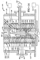
- Fig. 8 shows the electromagnetic field produced by induction coil 104 and shows how the electromagnetic field focuses energy on susceptor 116 when switch 132 is closed. While Fig. 8 shows raw material falling into crucible 134, the same electromagnetic field pattern exists regardless of whether the crucible is filled or unfilled of raw material 122 prior to the time when material 122 becomes susceptible to inductive heating.
- Fig. 9 shows the electromagnetic field after raw material 122 has melted to form molten material 150 and when switch 132 is open, whereby the electromagnetic field focuses energy on molten portion 150 of the material within crucible 134. Due to the "disappearing" nature of melting coil 130, the energy being absorbed by melting coil 130 in the closed circuit mode largely shifts to the susceptible molten material in crucible 134 when melting coil 130 is in the open circuit mode.
- the vast majority of the energy being absorbed by melting coil 130 in the closed circuit mode is being absorbed by melting coil 130 in the closed circuit mode and the vast majority of the energy is being absorbed by the susceptible material when melting coil 130 is in the open circuit mode.
- the "vast majority” of the energy being absorbed by melting coil 130 in the closed circuit mode is easily 85 percent or more and often is 90 or 95 percent or more.
- the "vast majority” of the energy being absorbed by the susceptible material when melting coil 130 is in the open circuit mode is easily 85 percent or more and often is 90 or 95 percent or more.
- said percentage of the energy being absorbed by the melting coil in the closed circuit mode may be 99 percent or more and said percentage of the energy being absorbed by the susceptible material when the melting coil is in the open circuit mode may be 99 percent or more.
- induction furnace 100 provides a highly efficient means, via the "disappearing" melting coil, of inductively heating semiconductor materials and other materials in particulate form which are not initially susceptible to inductive heating but which become susceptible to inductive heating at higher temperatures or upon melting.
- furnace 200 is now described with reference to Figs. 10-11 .
- Furnace 200 is similar to furnace 100 except that the melting crucible has a different configuration and furnace 200 includes a generally cone-shaped member 214 within the crucible and a trap passage 218, each of which are described further below.
- Cone-shaped member 214 alters the flow pattern of currents within molten material in the crucibles.
- Trap passage 218 serves to control the flow of molten material out of the crucible via pressure differentials on either side of molten material within passage 218.
- Induction furnace 200 includes a crucible 202 having a substantially cylindrical side wall 204 extending upwardly from a bottom wall 206.
- Crucible 202 includes a melting cavity 203, which is in communication with a pressure control source 205 ( Fig. 14 ) for adjusting atmospheric pressure within melting cavity 203.
- bottom wall 206 includes a generally cone-shaped portion 208 tapering upwardly and inwardly from a substantially flat annular portion 210 to an exit opening 212 formed in cone-shaped portion 208 of bottom wall 206.
- Exit opening 212 is in communication with a transfer passage 213, which is in communication with a pressure control source 215 ( Fig. 14 ) for adjusting atmospheric pressure within passage 213:
- FIG. 11 Another feature of the invention ( Fig. 11 ) is a trap 217 which defines a passage 218 formed generally above cone-shaped portion 208 of bottom wall 206 and generally below cone-shaped member 214.
- Trap passage 218 may be formed between bottom wall 206 and cone-shaped member 214 when member 214 is mounted thereon. Alternately, passage 218 may be formed within bottom wall 208 or within cone-shaped member 214.
- Trap passage 218 has a lower entrance end 220 defining an opening 227 in communication with melting cavity 203 of crucible 202 and an upper exit end 222 defining an opening 229 in communication with exit opening 212.
- Passage 218 has a crest 219 and a nadir 221, each extending along the length of passage 218.
- Crest 219 has a lowermost point 223 at lower entrance end 220.
- Nadir 221 includes several points, including point 225 at exit end 222, which are higher than lowermost point 223 of crest 219.
- Lowermost point 223 of crest 221 is at entrance end 220. More broadly, however, the lowermost point of the crest of a trap passage which will function as later described, may be anywhere along the trap passage as long as the nadir of the passage has a point which is higher than the crest lowermost point and which is situated between the crest lowermost point and the exit end of the passage.
- trap passage describes only one category of trap passages.
- the passage may also, for example, be vertical in its entirety so that no crest or nadir extending along the length of the passage would exist.
- the exit end opening would be higher than the entrance end opening, and more particularly, the lowermost point of the exit end opening of the passage would be higher than the uppermost point of the entrance end opening.
- certain passages having a portion with vertical walls and another portion which is inclined which may not fall within either of the two categories noted. Such variations are within the scope of the present invention and can easily be discerned by one skilled in the art.
- furnace 200 includes a feed mechanism 224 similar to feed mechanism 124 except for a valve 226 which is distinct from valve 128.
- Valve 226 is a substantially flat disc shape member.
- Furnace 200 also includes a preheat tube 228 which is similar to tube 118 of furnace 100, except its finds a plurality of exit openings 230 situated in an annular fashion for aligning raw material 122 to generally fall between cone-shaped members 214 and side wall 204 of crucible 202.
- furnace 200 functions as follows. Similar to furnace 100, raw material 122 in granular, powdered or other small-particle form, is fed through feed port 24 into the interior chamber of preheat tube 228 and is preheated as previously discussed. The flow of raw material 122 into melting cavity 203 of crucible 202 is controlled by feeding mechanism 224 whereby valve 226 moves in a vertical fashion between an open position to allow material to flow through exit openings 230 and a closed position to close openings 230 to prevent material from flowing.
- Fig. 11 shows valve 228 in the closed position to prevent raw material from flowing and crucible 202 prior to being charged with raw material 122.
- Fig. 12 shows valve 226 of feed mechanism 224 in a raised open position to allow raw material 122 to flow into melting cavity 203 of crucible 202 via exit openings 230.
- Fig. 13 shows raw material 122 continuing to flow through openings 230 and an initial stage of the melting process caused by electric power from power supply 26 flowing through induction coil 104 to inductively heat melting coil 130 in the closed circuit mode as previously described with regard to furnace 100.
- molten portion 150 within melting cavity 203 has become susceptible to inductive heating by induction coil 104 so that melting coil 130 may be switched to the open circuit mode to prevent further inductive heating of melting coil 130 and to allow inductive heating of molten material 150.
- Fig. 13 shows some of molten material 150 within trap passage 218.
- trap 217 is configured so that the portion of molten material 150 in passage 218, forms a liquid seal between entrance end 220 and exit end 222, whereby a pressure differential on the molten material within passage 218 from respective ends 220 and 222 may be controlled to either prevent molten material 150 from flowing into transfer passage 213 ( Fig. 14 ) or allow material 150 to flow out of melting cavity 203 and through exit opening 212 into transfer passage 213 ( Fig. 10 ).
- One way of creating a pressure differential to make molten material flow from melting cavity 203 is to add sufficient material, molten and/or raw, to melting cavity 203 to overcome the pressure from exit end 222. As raw material 122 melts, a sufficient amount of molten material 150 will be produced so that it will naturally flow out through exit opening 212 absent other controls. Thus, controlling the pressure of the atmosphere exerted on molten material 150 in passage 218 from entrance end 220 and exit end 222 provides control of the flow of molten material 150.
- Fig. 14 shows pressure control sources 205 and 215 for controlling this atmospheric pressure.
- Source 205 may decrease atmospheric pressure from entrance end 220 and/or source 215 may increase atmospheric pressure from exit end 222 to counter the pressure from molten material 150 in melting cavity 203 in order to prevent the flow of molten material through exit opening 212. Alternately, source 205 may increase atmospheric pressure from entrance end 220 and/or source 215 may decrease atmospheric pressure from exit end 222 to allow molten material 150 to flow.
- the height of the trap passage also controls flow of molten material 150 out of crucible 202. Increasing the height allows more molten material 150 to collect in the trap passage, and consequently in melting cavity 203, without the need to use a pressure differential to prevent flow through the exit opening.
- This basic concept is illustrated in Fig. 13 which shows that insufficient material 122 has been melted to raise the level of molten material 150 within passage 218 above exit opening 212.
- Fig. 14 shows an intermediate stage of melting and Fig. 15 shows all the material within crucible 202 in a molten state.
- valve 226 is in a closed position to prevent further addition of raw material 122, and switch 132 is in the open position and molten material is being inductively heated directly by induction coil 104.
- cone-shaped member 214 has altered the quadrature flow pattern discussed above with reference to Fig. 9 so that the molten material within melting cavity 203 flows as indicated by Arrows C in Fig. 14 and Arrows D in Fig. 15 .
- current flow in the lower quad rant flows downward in the central region of the melting cavity and upward in the outer region.
- the inward flow within the molten material which would have turned downwardly in the central region of the lower quadrants, is translated by the tapered shape of cone-shaped member 214 and forced upwardly instead.
- the molten material moves more rapidly overall and creates a higher positive meniscus between cone-shaped member 214 and side wall 204 of crucible 202.
- This increased velocity and turbulence creates an improved ability to draw the small-particle raw material 122 into the molten material to significantly enhance the melting process.
- this new current flow provides a higher meniscus and thus increases the surface area of the molten material to provide greater overall contact between the raw material and the molten material.
- Another benefit of this flow is the production of greater homogeneity of temperature within the molten material.
- This improved temperature uniformity within the melt translates to a more uniform temperature within the crucible, which is particularly helpful regarding the bottom wall, and thus increases the life of the crucible. Further, to the extent that there is a difference of temperature within the molten material, the hotter portion is at the top of the melt, which improves melting of the solid raw material and also prevents superheating at the bottom of the melt which could lead to melting the crucible.
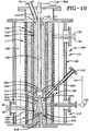
- furnace 300 is similar to furnace 100 except that furnace 300 includes a disc-shaped susceptor 302 positioned below crucible 134 closely adjacent bottom wall 140 thereof. Preferably, susceptor 302 abuts bottom wall 140. Susceptor 302 has a substantially cylindrical outer perimeter 304 and an inner perimeter 306 defining a central hole 308. Susceptor 302, typically a graphite disc, is not a significant expense.
- outer perimeter 304 of susceptor 302 is further away from induction coil 104 than is an inner surface 312 of crucible side wall 138. More particularly, susceptor 302 and crucible 134 are configured so that a space 310 within melting cavity 146 is closer to induction coil 104 than is susceptor 302 so that a portion of molten material 150 within space 310 may be closer to coil 104 than is susceptor 302. Space 310 lies between inner surface 312 of side wall 138 and an imaginary cylinder defined by lines E extending upwardly from outer perimeter 304 of susceptor 302. Thus, space 310 is disposed within melting cavity 146 all the way around the cylinder defined by lines E and adjacent sidewall 138 along bottom wall 140.
- furnace 300 operates as follows.
- Fig. 17 shows crucible 134 prior to being charged with raw material 122.
- Fig. 18 shows crucible 134 being charged with raw material 122.
- electrical power from powers supply 26 produces an electrical current through induction coil 104 and switch 132 is in the closed position whereby susceptor or switchable coil 130 is inductively heated by the electromagnetic field produced by coil 104 as previously described.
- melting coil 130 and susceptor 302 are used in conjunction to melt the initial portion 150 of raw material 22, as shown in Fig. 19 , so that molten portion 150 may then be inductively heated directly by induction coil 104.
- portion 150 has become inductively heatable, switch 132 is opened as discussed above, whereby inductive heating of melting coil 130 ceases.
- Susceptor 302 remains in place and continues to be inductively heated decreasingly as molten material 150 is increasingly inductively heated. Due to the configuration of susceptor 302 described above, the portion of molten material 150 within space 310 is closer to induction coil 104 than is susceptor 302 whereby inductive heating naturally tends towards the molten material because it is closer to induction coil 104.
- energy absorbed by molten material 150 from the electromagnetic field produced via induction coil 104 increases and energy absorbed by susceptor 302 from the electromagnetic field decreases.
- susceptor 302 permits it to nearly "disappear" to the inductive heating effect from induction coil 104.
- Fig. 20 shows an intermediate stage of melting wherein a portion of raw material 122 is molten and a portion is still in solid form.
- Switch 132 is in the open position so that melting coil 130 is no longer being inductively heated.
- Susceptor 302 at this point is still being inductively heated to some degree although this is decreasing as previously noted.
- Fig. 21 By the time all the material within crucible 134 is molten, as shown in Fig. 21 , essentially all the inductive heating taking place is occurring directly within molten material 150 while a relatively small amount is occurring within susceptor 302.
- Hole 308 in susceptor 302 allows for a central pouring mechanism so that molten material may flow through hole 308.
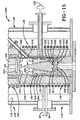
- Additional material 122 may be added via exit opening 129 and molten material may be removed through exit opening 142, as shown in Fig. 16 , so that furnace 300 is capable of continuous and intermittent melting.
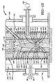
- furnace 400 is similar to furnace 100 except that furnace 400 includes a melting coil 430, which acts as a susceptor and is disposed within melting cavity 146 of crucible 134 instead of outside crucible 134. Because melting coil 430 is situated centrally within melting cavity 146, a feed mechanism like feed mechanism 224 used with the furnace 200 is utilized. The location of melting coil 430 within crucible 134 may vary, however, and thus other feed mechanisms may be more suitable depending on said location and the specific configuration of such an internal susceptor.
- Melting coil 430 is encased within a refractory material 432 such as ceramic, although this may vary in accordance with the material to be melted or heated.
- the basic concept of melting coil 430 is the same as that of melting coil 130 other than its location. More specifically, melting coil 430 may be switched between an open circuit mode and a closed circuit mode via switch 132 and is thus heatable as described with respect to furnace 100.
- the melting pattern which occurs with the use of melting coil 430 differs in that material 122 begins to melt adjacent melting coil 430 instead of adjacent sidewall 138.
- induction coil 104 will tend to couple with material 122 in preference to coupling with melting coil 430 even when the circuit is closed because some susceptible material is closer to induction coil 104 than is melting coil 430, as explained with regard to susceptor 302 of furnace 300. Opening the circuit of melting coil 430, however, further removes melting coil 430 from being inductively heated, as with the other "disappearing" coils.
- induction furnaces 100, 200, 300 and 400 provide novel configurations and methods of inductively heating and melting particulate material which is initially not inductively heatable and which becomes inductively heatable when heated to a certain temperature and especially upon melting. It will be appreciated that a great number of changes may be made to each of these furnaces without departing from the spirit of the invention. It will be appreciated that each of these furnaces may function without the preheating assembly although this facilitates the melting process. In addition, the preheating assembly may be of other suitable configurations which do not use inductive heating.
- Furnaces 100, 200, 300 and 400 utilize the "disappearing" melting coil 130 or 430 particularly for melting such materials as described herein.
- the concept of the disappearing coil may be utilized in a wide variety of circumstances. It need not be used for melting purposes, but may be used simply to inductively heat something in a selective fashion whereby the switch may be turned on and off as desired.
- melting coil 130 or 430 need not be in a coil form but merely needs to form a closed circuit when a switch is closed and an open circuit when the switch is open whereby it can be inductively heated when the switch is closed. Further, melting coil 130 or 430 need not be disposed within an induction coil which is in the form of a cylinder or other shape.
- melting coil 130 or 430 may be positioned externally near an induction coil so that it is within the electromagnetic field produced thereby.
- the electromagnetic field which inductively heats melting coil 130 or 430 need not be produced by an induction coil but by any induction member through which an electrical current may be passed to create an electromagnetic field capable of inductively heating melting coil 130 or 430 or a similar disappearing coil.
- the exemplary embodiments are preferred due to heir levels of efficiency.
- the use of the disappearing coil is not limited to melting or heating only particulate material. It may also be used to melt or heat larger pieces of material. Thus, for example, the disappearing coil may be effectively used with larger pieces of materials which, like semi-conductor materials, are not inductively heatable in solid form regardless of size.
- the present invention may also be used with fibrous materials or other materials having geometries which are particularly difficult to melt via inductive heating.
- Certain liquids are also particularly suited to heating with the present invention, for example, those liquids which are not susceptible to inductive heating at a relatively lower temperature but which are susceptible to inductive heating at relatively higher temperature.
- the invention is also suitable for heating liquids which are susceptible to inductive heating at relatively higher frequencies (i.e., higher frequency electrical current to the induction coil) at a relatively lower temperature and which are susceptible to inductive heating at relatively lower frequencies at a relatively higher temperature due to the corresponding lowered resistivity of the liquid at the higher temperature. This may include scenarios wherein such liquids are simply not inductively heatable at the relatively lower frequency when the liquid is at the relatively lower temperature.
- This may also include scenarios wherein such liquids are susceptible to inductive heating to some degree at the lower frequency and lower temperature, but only at a relatively lower efficiency, while this efficiency increases at the lower frequency when the temperature of the liquid is sufficiently raised.
- the invention is particularly useful in that the disappearing coil can heat such liquids to bring them into a temperature range where commercially feasible lower frequencies can be used to inductively heat the liquids, substantially increasing the efficiency of heating such liquids.
- the flow guide embodied as a cone-shaped member in induction furnace 200, may also take a variety of shapes, although a general cone shape is preferred, particularly with a cylindrical crucible and cylindrical induction coil.
- Other shapes which alter the flow of the molten material so that currents in the central or interior regions of a crucible melting cavity tend to flow upwardly rather than downwardly are within the scope of the concept of the present invention.
- such a change in the current flow within the molten material prevents overheating of the crucible bottom wall, provides greater uniformity of temperature within the melt and adds to the ability to draw raw material into the melt.
- Some of the obvious alternatives include a cone shape that has a convex or a concave outer surface.
- pyramidal shapes may be used or cone shapes that may have ridges and recesses such as a star-shaped cone-like structure.
- Other possibilities include a tent-shaped member having elongated sides which taper upwardly and inwardly or an elongated mound shape having a parabolic or semicircular cross section.
- the outer surface of the member in issue is preferably continuous, it may also be noncontinuous and may be created by a plurality of members in combination. A host of other configurations is within the scope of the present invention.
- a trap passage may be created by, for example, forming slots or other openings in the lower portion of the cone-shaped member. Further, such passages do not require the use of a cone-shaped member or the like. Consequently, the crucible bottom wall need not be generally cone-shaped, but may, for example, be substantially flat with a tube extending upwardly into the melting cavity to provide a raised exit opening in communication with an upper portion of the trap passage.
- the trap passage may also be disposed outside of the crucible, such as may be defined by a pipe extending outwardly from the crucible side wall.
- valve used in the preheating assembly may be used without a preheating assembly and may be of a variety of configurations, While it is preferable to guide the raw material directly onto the upper surface of the molten material, the raw material may also fall on to the cone-shaped member and so forth.
- susceptor 302 need not be disc-shaped or have a hole formed therein.
- Susceptor 302 may have a variety of shapes as long as some space within the crucible melting cavity for holding a molten portion is closer to the induction coil than is the susceptor itself, whereby the susceptible molten material is preferentially inductively heated with respect to a susceptor analogous to susceptor 302. While susceptor 302 is typically made of graphite, it may be formed of any material capable of being inductively heated.
Description
- The invention relates to induction heating and an improved induction furnace. More particularly, the invention relates to an induction furnace for melting materials not susceptible to inductive heating at lower temperatures but which are susceptible to inductive heating at higher temperatures, especially upon melting. Specifically, the invention relates to an induction furnace capable of continuously or intermittently melting such materials.
- Induction furnaces are well known in the art. However, there are a variety of difficulties related to the inductive heating and melting of materials that are initially non-conductive or which have particle sizes sufficiently small so that they are not susceptible to inductive heating. Many prior art induction furnaces utilize a conductive crucible such that an induction coil couples with the crucible to transfer energy directly to the crucible to heat the crucible whereby heat is then transferred from the crucible to the material to be melted via thermal conduction. In certain cases, the induction frequency and the thickness of the crucible wall may be selected so that a portion of the electromagnetic field from the coil allows coupling with electrically conductive material inside the crucible to inductively heat the material directly. However, the direct inductive heating in such cases is quite limited. Because direct inductive heating of the material to be melted is far more effective than the method described above, a system to effect such direct inductive heating is highly desirable.
- In addition, the conductive crucibles of the prior art may react with the material to be melted which causes unwanted impurities in the melt and thus requires the use of a non-reactive liner inside the crucible to prevent formation of such impurities. Typically, however, such liners are electrically non-conductive and thermally insulating. As a result, the transfer of heat from the crucible to the materials to be melted is greatly impeded and thus melting times are substantially increased. To expedite the transfer of heat from the crucible to the material to be melted, the crucible must be heated to undesirably high temperatures which can decrease the life of the crucible and liner.
- In addition, there remains a need for an induction furnace capable of producing a continuous melt in an efficient manner, especially for semi-conductor materials. An efficient continuous melt induction furnace is particularly useful related to continuous formation of semi-conductor crystals, which are highly valued in the production of computer chips.
-
US patent 6,361,597 to Takase et al. teaches three embodiments of an induction furnace especially intended for melting semi-conductor materials and adapted to supply the molten material to a main crucible for pulling of semi-conductor crystals therefrom. Unlike the prior art discussed above, Takase et al. uses a quartz crucible which is electrically non-conductive along with a susceptor which is in the form of a carbon or graphite cylinder. In each of the three embodiments of Takase et al., the carbon or graphite cylinder susceptor is initially inductively heated by a high frequency coil whereby heat is transferred from the susceptor to raw material inside the crucible in order to begin the melting process. Once the raw material is melted, it is directly inductively heated by the high frequency coil in order to speed up the melting process. While this is a substantial improvement over the previously discussed prior art, the induction furnace of Takase et al. still leaves room for improvement. - The first two embodiments of Takase et al. involve the use of a carbon cylinder susceptor which encircles the quartz crucible and is movable in a vertical direction. This provides a mechanism whereby the susceptor may bye inductively heated and then either moved out of the electromagnetic field of the induction coil altogether or moved to a position which is more advantageous for heating selected portions of the material within the crucible. One drawback of this configuration is the need for a mechanism to move the susceptor in a vertical direction. The third embodiment of Takase et al. provides a susceptor having a crucible-like configuration with a cylindrical side wall of the susceptor covering the side wall of the quartz crucible and a bottom of the susceptor covering the bottom wall of the quartz crucible. The susceptor is not vertically moveable in the third embodiment. Instead, the thickness of the susceptor sidewall and the frequency applied by the coil are selected so that the penetration depth of the induction current will extend beyond the susceptor into the quartz crucible so that it can inductively heat material inside. The third embodiment of Takase et al. primarily suffers from the fact that the cylindrical susceptor remains in place and thus prevents inductive heating from more effectively being focused on the raw material within the crucible. Instead, the coil continues to inductively heat the carbon cylinder so that energy which might be applied to the material is absorbed by the carbon cylinder, which transfers heat to the raw material in the crucible in a far less effective manner.
- It is further know a floating zone melting process for purifying or refining semiconductor rods or crystals. More particularly, as a directly inductively heated crystal is pulled through the heater, a narrow region of the crystal is molten, whereby this molten zone moves along the crystal. In short, impurities are concentrated in the molten zone and are moved to one end of the crystal or ingot.
-
DE2637939 discusses one of the problems with this method, for instance electrical discharges or flash-overs between the induction coil and the directly inductively semiconductor rod or other parts of the apparatus. It was known to disconnect the HF generator or AC electric source immediately when a flash-over occurs to avoid damaging the arrangement. However, this prior art practice made the rod unusable. It is disclosed to automatically disconnect the energy supply to the induction heating coil immediately if a flash-over occurs arid then automatically reconnect the energy supply to the induction coil. BRIEF SUMMARY - The present invention provides an apparatus for heating a material, the apparatus comprising an electromagnetic induction member; an electrically conductive member selectively switchable between a closed electrical circuit and an open electrical circuit whereby the conductive member is inductively heatable by the induction member via the closed electrical circuit and whereby when the conductive memberforms the open electrical circuit, inductive heating of the conductive member by the induction member which would occur if the conductive member formed the closed electrical circuit is eliminated; and the conductive member being adapted to transfer heat to the material. The present invention also provides a method of heating material comprising the steps of: heating an electrically conductive member inductively with an electromagnetic induction member when the conductive member is in a closed electrical circuit mode; transferring heat from the conductive member to the material; and switching the conductive member to an open circuit mode to prevent further inductive heating of the conductive member which would occur if the conductive member remained in the closed circuit mode.
- The present invention further provides an apparatus for heating a material, the apparatus comprising an electrically conductive member selectively switchable between a closed electrical circuit mode and an open electrical circuit mode; the conductive member being resistively heatable when in the closed circuit mode and not being resistively heatable when in the open circuit mode; the conductive member being adapted to transfer heat to the material; and an electromagnetic induction member adapted to inductively heat the material.
- The present invention also provides a method of heating material comprising the steps of heating an electrically conductive member resistively when the conductive member is in a closed electrical circuit mode; transferring heat from the conductive member to the material; heating the material inductively with an electromagnetic induction member; and switching the conductive memberto an open circuit mode to prevents inductive heating of the conductive member which would occur if the conductive member remained in the closed circuit mode.
- The present invention further provides an apparatus comprising a crucible defining a melting cavity; an electromagnetic induction member for inductively heating molten material within the melting cavity; and a flow guide disposed within the melting cavity for directing the inductively heated molten material to flow upwardly within the cavity.
- The present invention also provides an apparatus comprising a crucible defining a melting cavity and an exit opening; and a trap defining a through passage having an entrance end defining an opening in communication with the melting cavity and an exit end defining an opening in communication with the exit opening of the crucible for transporting molten material from the melting cavity to the exit operning of the crucible whereby the relative pressure exerted on molten material in the passage controls the flow of molten material through the exit opening.
- Preferred embodiments of the invention, illustrative of the best modes in which applicant contemplates applying the principles, are set forth in the following description and are shown in the drawings and are particularly and distinctly pointed out and set forth in the appended claims.
-
Fig. 1 is a side elevational view of a first embodiment of the induction furnace of the present invention in use with a preheating assembly and crystal formation apparatus. -
Fig. 2 is an enlarged sectional view of the furnace ofFig. 1 showing the first embodiment in use with the preheating assembly. -
Fig. 3 is an enlarged fragmentary sectional view of the furnace shown inFig. 2 showing the crucible empty. -
Fig. 4 is similar toFig. 3 but showing an initial charge of raw material in the crucible. -
Fig. 5 is similar toFig. 4 containing an initial molten portion of the raw material. -
Fig. 6 is similar toFig. 5 showing a further stage of melting. -
Fig. 7 is similar toFig. 6 showing all the material within the crucible in a molten state. -
Fig. 8 is a diagrammatic view showing the electromagnetic field acting on the melting coil. -
Fig. 9 is similar toFig. 8 showing the electromagnetic field acting on the molten material within the crucible, and showing electromotive forces acting on the molten material and currents within the molten material. -
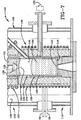
Fig. 10 is similar toFig. 2 showing a second embodiment of the induction furnace of the present invention with a generally cone-shaped member within the melting cavity and a trap passage for controlling the flow of molten material from the crucible. -
Fig. 11 is an enlarged fragmentary sectional view of the furnace shown inFig. 10 wherein the crucible is empty. -
Fig. 12 is similar toFig. 11 showing an initial charge of raw material entering the crucible. -
Fig. 13 is similar toFig. 12 showing an initial molten portion of the raw material. -
Fig. 14 is similar toFig. 13 showing a further stage of the melting process. -
Fig. 15 is similar toFig. 14 showing all material in the crucible is molten. -
Fig. 16 is similar toFig. 2 showing a third embodiment of the present invention which includes a susceptor disk beneath the crucible. -
Fig. 17 is an enlarged fragmentary sectional view of the furnace shown inFig. 16 wherein the crucible is empty. -
Fig. 18 is similar toFig. 17 showing an initial charge of raw material in the crucible. -
Fig. 19 is similar toFig. 18 showing an initial molten portion of the raw material. -
Fig. 20 is similar toFig. 19 showing a further stage of melting. -
Fig. 21 is similar toFig. 20 showing all of the material in the crucible in a molten state. -
Fig. 22 is similar toFig. 4 showing a fourth embodiment of the induction furnace of the present invention with the melting coil/susceptor disposed within the melting cavity and a feed mechanism like that inFig. 12 . - Similar numbers refer to similar parts throughout the specification.
- The improved induction furnace of the present invention is shown in four embodiments in the figures although other embodiments are contemplated as is apparent to one of skill in the art. Specifically, the first embodiment of the induction furnace is indicated generally at 100, and is shown in
Figs. 1-3 , the second embodiment is indicated generally at 200, and is shown inFigs. 8-9 , the third embodiment is indicated generally at 300, and is shown inFigs. 16-17 and the fourth embodiment is indicated generally at 400, and is shown inFig. 22 . - With reference to
Fig. 1 ,furnace 100 is mounted on asupport stand 10 via asupport arm 12 extending therefrom, althoughfurnace 100 may be supported by any suitable means.Furnace 100 is disposed above and connected to a standardcrystal formation apparatus 16 which contains aninterior chamber 18 in which is disposed a receiving crucible or tundish 20. Acharge feeder 22 situated abovefurnace 100 is in communication with afeed port 24 whereby raw material may be fed intofurnace 100. As shown inFigs. 1-2 , apower supply 26 is in electrical communication viawires 28 with apreheating induction coil 102 and amelting induction coil 104.Power supply 26 may also be in electrical communication viawires 30 with amelting coil 130. - With reference to
Fig. 2 , a double-walled heating container 106 defines aninterior chamber 108 which is divided into apreheat zone 110 and amelting zone 112 there below. A preheatingassembly 114 is disposed within preheatzone 110 and includes acylindrical susceptor 116 disposed within preheatinginduction coil 102 and apreheat tube 118 disposed withinsusceptor 116 and closely adjacent or in abutment withsusceptor 116.Preheat tube 118 defines aninterior chamber 120 for receivingraw material 122 fromfeed port 24 for preheating the raw material. Afeed mechanism 124 includes acontrol arm 126 with avalve 128 at the terminal end thereof.Valve 128 is selectively seated inexit opening 129 formed in the lower end of preheattube 118.Furnace 100 further defines aquiescent zone 131 belowpreheat assembly 114, as detailed further below. - In accordance with one of the main features of the present invention and with reference to
Figs. 2-3 , substantiallycylindrical melting coil 130, which acts as a susceptor, is disposed withinmelting induction coil 104 and is switchable between a closed electrical circuit mode and an open electrical circuit mode viaswitch 132. Amelting crucible 134 is disposed withinmelting coil 130 and in combination withmelting induction coil 104 andmelting coil 130, forms amelting assembly 136.Melting coil 130 may provide lateral support forcrucible 134. - Melting
crucible 134 includes a substantiallycylindrical side wall 138 extending upwardly from a substantially flatbottom wall 140 which defines anexit opening 142 through which the flow of molten material is controlled by any suitable mechanism known in the art. Meltingcrucible 134 defines amelting cavity 146 in communication with exit opening 142 ofbottom wall 140 as well as exit opening 129 oftube 118. In addition, alaser sight port 148 is in visual communication withmelting cavity 146. - In operation, and with reference to
Figs. 1-7 ,furnace 100 functions as follows. Referring toFigs. 1-3 ,raw material 122 is fed viacharge feeder 22 intofeed port 24 and subsequently intointerior chamber 120 of preheatingtube 118. Valve 128 (an angle of repose valve) is initially in a closed position (Fig. 3 ) to preventraw material 122 from passing throughexit hole 129.Power supply 26 is then operated to provide electrical power throughwires 28 to preheatinginduction coil 102.Induction coil 102 thus produces an electromagnetic field so thatcoil 102 couples withsusceptor 116 toinductively heat susceptor 116. In turn,susceptor 116 transfers heat toraw material 122 through preheatingtube 118 via conduction and radiation.Raw material 122 is thus heated to a point below the melting temperature of the material prior to chargingcrucible 134.Raw material 122 is typically granular, powdered or of another particulate form. Oncematerial 122 is sufficiently heated,feed mechanism 124 is operated to openvalve 128 whereby a portion ofmaterial 122 is released intomelting cavity 146 ofcrucible 134, as shown inFig. 4 .Feed mechanism 124 is configured to control the rate at whichmaterial 122 falls intomelting cavity 146. - In accordance with another feature of the invention and with reference to
Fig. 5 ,power supply 26 provides electrical power to meltinginduction coil 104 which creates an electromagnetic field so thatinduction coil 104 couples withmelting coil 130 to inductivelyheat melting coil 130. Inductive heating ofmelting coil 130 occurs whenswitch 132 is closed andmelting coil 130 thereby forms a closed electrical circuit wherebymelting coil 130 is thus initially operated in a closed electrical circuit mode. Once inductively heated,melting coil 130 transfers heat toraw material 122 in meltingcavity 146 ofcrucible 134 predominantly throughside wall 138 ofcrucible 134. As shown inFig. 5 , an initial portion ofraw material 122 has melted, the molten portion indicated at 150. During this initial melting process, it has been found that having aportion 152 ofmelting coil 130 disposed above the charge ofmaterial 122 in melting cavity 146 (that is, thematerial 122 resting withincrucible 134 as opposed to thematerial 122 in a state of falling from preheat tube 118) substantially increases the initial melting rate. This is due to the radiation heat withinmelting cavity 146 above the charge ofmaterial 122 coming fromportion 152 ofmelting coil 130, which compensates for radiation heat loss from said charge ofmaterial 122, so that said charge is heated more quickly. Once a sufficient portion ofmaterial 122 has been melted by heat transferred from meltingcoil 130,molten portion 150 becomes susceptible to inductive heating byinduction coil 104. Becausemelting coil 130 is heating throughside wall 138,molten material 150 will include a cylindrical portion which flows down to form a pool portion. The cylindrical portion alongside wall 138 provides a greater surface area of susceptible material in comparison to the pool portion, so that direct inductive heating ofmaterial 150 is enhanced thereby (Figs. 5-6 ). - Anotherfeature of the present invention is
heating melting coil 130 resistively, either in combination with the inductive heating or as the sole source ofheating melting coil 130. To do this,power supply 26 provides electrical power to meltingcoil 130 viawires 30 while meltingcoil 130 forms a closed electrical circuit. Whether used alone or in combination with inductive heating ofmelting coil 130, the heating ofmaterial 122 thereby is continued until a portion ofmaterial 122 becomes susceptible to inductive heating. - In accordance with another feature of the present invention, once
portion 150 becomes susceptible to inductive heating,switch 132 is opened so that meltingcoil 130 is in an open electrical circuit mode whereby inductive heating ofmelting coil 130 byinduction coil 104 is predominantly eliminated. More particularly, when meltingcoil 130 is in the open electrical circuit mode or forms an open electrical circuit, inductive heating ofmelting coil 130 byinduction coil 104 which would occur if meltingcoil 130 were in the closed electrical circuit mode is eliminated. Ifmelting coil 130 is heated solely by resistance or by resistance in combination with inductive heating byinduction coil 104, opening the closed circuit ofmelting coil 130 also terminates resistive heating. Thus, withmelting coil 130 being in an open electrical circuit mode, meltingcoil 130 has largely "disappeared" toinduction coil 104, absorbing very little further energy from the electromagnetic field produced byinduction coil 104, as discussed further below. Instead,induction coil 104 couples with the susceptiblemolten material 150 to directly inductively heatmolten portion 150. This direct inductive heating of thesusceptible material 150 permits heat to be transferred frommolten portion 150 to solidraw material 122 to continue to melt material whereby the additional molten material also becomes susceptible to inductive heating. The "disappearance" ofmelting coil 130 to inductive heating decreases the heat imparted tocrucible 134, which tends to extend the life ofcrucible 134. -
Fig. 5 also shows the continued addition ofraw material 122 after melting has begun.Furnace 100 is configured to addraw material 122 as desired. It is often desirable to continuously or intermittently addraw material 122 throughout the melting process to provide continuous or intermittent melting and transfer ofmolten material 150 out ofcrucible 134. However,raw material 122 may simply be added in a batch form and melted in its entirety without further additions. -
Fig. 6 shows a further stage of melting withswitch 132 in the open position wherebymelting coil 130 has "disappeared" tocoil 104, as noted above. Melting ofraw material 122 proceeds via direct inductive heating ofmolten material 150 until all the material withinmelting cavity 146 is molten, as shown inFig. 7 . Switch 132 remains in the open position, as the inductive heating ofmelting coil 130 is not needed or desired after initialmolten portion 150 becomes directly heatable by induction. Additionalraw material 122 may then be added to the fully molten material, as shown inFig. 2 . Molten material may then be released through exit opening 142 to make room for additional raw material to entermelting cavity 146 so thatfurnace 100, as noted above, is capable of continuous or intermittent melting. As previously noted, wheninduction furnace 100 is used with semiconductor materials, molten semiconductor material may be transferred intermittently or continuously intotundish 120 from which semi-conductor materials may be processed or crystals may be pulled. - Another feature of the invention is quiescent zone 131 (
Fig. 2 ), which is disposed belowpreheat assembly 114 and provides sufficient space to prevent obstruction of the flow ofparticulate material 122 frompreheat assembly 114 tomolten material 150 withinmelting cavity 146. Several problems may arise absentquiescent zone 131, three of which are specified: sticking, premature melting and wicking. Each of these problems relates to the distance between the lower end of preheat assembly 114 (as at exit opening 129 of preheat tube 118) and a source of heat there below. Typically, the source of this heat ismolten material 150 withinmelting cavity 146 as heated byinduction coil 104. The first two of these problems, sticking and premature melting, are due to overheating ofmaterial 122 just prior to exiting frompreheat assembly 114 as a result of heat created withinmelting zone 112 and radiating withinmelting cavity 146 towardpreheat assembly 114. - Sticking is when material 122 becomes sufficiently hot (at a sub-melting temperature) to cause particles of
material 122 to stick to one another and to preheatassembly 114, thus obstructing the flow ofmaterial 122 frompreheat assembly 114. Premature melting is essentially an advanced stage of sticking, wherebymaterial 122 melts prior to exitingpreheat assembly 114. The resultant molten material then sticks to preheatassembly 114 and similarly obstructs the flow ofmaterial 122 therefrom whether the material remains molten or freezes onpreheat assembly 114. Thus, sticking and premature melting both involve particles ofmaterial 122 sticking to preheatassembly 114. Premature melting makes correction of the problem more difficult due to molten material ultimately freezing and bonding with greater tenacity to preheatassembly 114 than in the case of "sticking", wherein the particles do not melt. - The third problem, wicking, relates primarily to the distance between
preheat assembly 114 and anupper surface 154 ofmolten material 150 withinmelting cavity 146. Wicking is when a portion ofmolten material 150 withinmelting cavity 146 wicks upwardly within interstitial spaces between particles ofmaterial 122 via capillary action. When wicking occurs, sufficient heat from said portion ofmolten material 150 is absorbed byparticulate material 122 so that said portion freezes and forms a bridge betweenmolten material 150 in meltingcavity 146 andpreheat assembly 114, thus obstructing the flow ofmaterial 122 frompreheat assembly 114.Quiescent zone 131 is of sufficient size to prevent obstruction of the flow ofmaterial 122 in regard to each of these three problems. -
Fig. 8 shows the electromagnetic field produced byinduction coil 104 and shows how the electromagnetic field focuses energy onsusceptor 116 whenswitch 132 is closed. WhileFig. 8 shows raw material falling intocrucible 134, the same electromagnetic field pattern exists regardless of whether the crucible is filled or unfilled ofraw material 122 prior to the time whenmaterial 122 becomes susceptible to inductive heating. By contrast,Fig. 9 shows the electromagnetic field afterraw material 122 has melted to formmolten material 150 and whenswitch 132 is open, whereby the electromagnetic field focuses energy onmolten portion 150 of the material withincrucible 134. Due to the "disappearing" nature ofmelting coil 130, the energy being absorbed by meltingcoil 130 in the closed circuit mode largely shifts to the susceptible molten material incrucible 134 when meltingcoil 130 is in the open circuit mode. - Thus, of the total energy being absorbed by melting
coil 130 and the susceptible material withincrucible 134, the vast majority of the energy is being absorbed by meltingcoil 130 in the closed circuit mode and the vast majority of the energy is being absorbed by the susceptible material when meltingcoil 130 is in the open circuit mode. Typically, the "vast majority" of the energy being absorbed by meltingcoil 130 in the closed circuit mode is easily 85 percent or more and often is 90 or 95 percent or more. Similarly, the "vast majority" of the energy being absorbed by the susceptible material when meltingcoil 130 is in the open circuit mode is easily 85 percent or more and often is 90 or 95 percent or more. Where the melting coil or susceptor is appropriately configured, said percentage of the energy being absorbed by the melting coil in the closed circuit mode may be 99 percent or more and said percentage of the energy being absorbed by the susceptible material when the melting coil is in the open circuit mode may be 99 percent or more. - As is known in the art and with continued reference to
Fig. 9 , electric current flowing throughinduction coil 104 creates electromotive forces as indicated by Arrows A, which causemolten material 150 to flow in the direction shown by Arrows B, which show a pattern of current flow known as "quadrature" flow. This current flow within the molten material causes the molten material to have a positive meniscus and creates flow along the surface which aids in drawingraw material 122 into the melt. This is particularly helpful with small-sized particles which otherwise tend to sit atop the molten material due to the surface tension thereof. However, the ability of the quadrature flow to drawraw material 122 into the melt still has limitations and feeding powdered or otherparticulate material 122 too rapidly into the melting cavity can result in a dome of unmelted material known as a "bridge" sitting atop the molten material. This can cause superheating of the molten bath, leading to excessive refractory wear and potentially to melting of the crucible. As Arrows B inFig. 9 show, in the upper quadrants, the currents flow upward in the central region and downward in the outer region alongside wall 138 ofcrucible 134. Currents in the lower quadrants generally flow downwardly in the central region and upwardly in the outer regionadjacent side wall 138, and thus have a pattern which is essentially the opposite of the upper quadrants. - In summary,
induction furnace 100 provides a highly efficient means, via the "disappearing" melting coil, of inductively heating semiconductor materials and other materials in particulate form which are not initially susceptible to inductive heating but which become susceptible to inductive heating at higher temperatures or upon melting. -
Induction furnace 200 is now described with reference toFigs. 10-11 .Furnace 200 is similar tofurnace 100 except that the melting crucible has a different configuration andfurnace 200 includes a generally cone-shapedmember 214 within the crucible and atrap passage 218, each of which are described further below. Cone-shapedmember 214 alters the flow pattern of currents within molten material in the crucibles.Trap passage 218 serves to control the flow of molten material out of the crucible via pressure differentials on either side of molten material withinpassage 218. -
Induction furnace 200 includes acrucible 202 having a substantiallycylindrical side wall 204 extending upwardly from abottom wall 206.Crucible 202 includes amelting cavity 203, which is in communication with a pressure control source 205 (Fig. 14 ) for adjusting atmospheric pressure withinmelting cavity 203. With reference toFig. 11 ,bottom wall 206 includes a generally cone-shapedportion 208 tapering upwardly and inwardly from a substantially flatannular portion 210 to anexit opening 212 formed in cone-shapedportion 208 ofbottom wall 206.Exit opening 212 is in communication with atransfer passage 213, which is in communication with a pressure control source 215 (Fig. 14 ) for adjusting atmospheric pressure within passage 213: - In accordance with another of the main features of the invention and with continued reference to
Figs. 10-11 , a flow guide in the form of substantially cone-shapedmember 214 is seated withincrucible 202 and mounted onbottom wall 206 thereof. Cone-shapedmember 214 tapers upwardly and inwardly from adjacentbottom wall 206 andsidewall 204 to an apex 216 (Fig. 11 ) centrally located within the melting cavity ofcrucible 202. Cone-shapedmember 214 has anouter surface 209 is radially symmetrical about a vertical central axis 211 (Fig. 11 ). Preferably, cone-shapedmember 214 extends to a height above the level to which molten material will rise withinmelting cavity 203 ofcrucible 202. - Another feature of the invention (
Fig. 11 ) is atrap 217 which defines apassage 218 formed generally above cone-shapedportion 208 ofbottom wall 206 and generally below cone-shapedmember 214.Trap passage 218 may be formed betweenbottom wall 206 and cone-shapedmember 214 whenmember 214 is mounted thereon. Alternately,passage 218 may be formed withinbottom wall 208 or within cone-shapedmember 214.Trap passage 218 has alower entrance end 220 defining anopening 227 in communication withmelting cavity 203 ofcrucible 202 and anupper exit end 222 defining anopening 229 in communication withexit opening 212.Passage 218 has acrest 219 and anadir 221, each extending along the length ofpassage 218.Crest 219 has alowermost point 223 atlower entrance end 220.Nadir 221 includes several points, includingpoint 225 atexit end 222, which are higher thanlowermost point 223 ofcrest 219.Lowermost point 223 ofcrest 221 is atentrance end 220. More broadly, however, the lowermost point of the crest of a trap passage which will function as later described, may be anywhere along the trap passage as long as the nadir of the passage has a point which is higher than the crest lowermost point and which is situated between the crest lowermost point and the exit end of the passage. - However, such a trap passage describes only one category of trap passages. The passage may also, for example, be vertical in its entirety so that no crest or nadir extending along the length of the passage would exist. For such a vertical passage, the exit end opening would be higher than the entrance end opening, and more particularly, the lowermost point of the exit end opening of the passage would be higher than the uppermost point of the entrance end opening. There are further variations, such as certain passages having a portion with vertical walls and another portion which is inclined, which may not fall within either of the two categories noted. Such variations are within the scope of the present invention and can easily be discerned by one skilled in the art.
- In addition, with reference to
Fig. 10 ,furnace 200 includes afeed mechanism 224 similar tofeed mechanism 124 except for avalve 226 which is distinct fromvalve 128.Valve 226 is a substantially flat disc shape member.Furnace 200 also includes apreheat tube 228 which is similar totube 118 offurnace 100, except its finds a plurality ofexit openings 230 situated in an annular fashion for aligningraw material 122 to generally fall between cone-shapedmembers 214 andside wall 204 ofcrucible 202. - As shown in
Figs. 10-15 ,furnace 200 functions as follows. Similar tofurnace 100,raw material 122 in granular, powdered or other small-particle form, is fed throughfeed port 24 into the interior chamber of preheattube 228 and is preheated as previously discussed. The flow ofraw material 122 intomelting cavity 203 ofcrucible 202 is controlled by feedingmechanism 224 wherebyvalve 226 moves in a vertical fashion between an open position to allow material to flow throughexit openings 230 and a closed position to closeopenings 230 to prevent material from flowing. -
Fig. 11 showsvalve 228 in the closed position to prevent raw material from flowing andcrucible 202 prior to being charged withraw material 122.Fig. 12 showsvalve 226 offeed mechanism 224 in a raised open position to allowraw material 122 to flow intomelting cavity 203 ofcrucible 202 viaexit openings 230.Fig. 13 showsraw material 122 continuing to flow throughopenings 230 and an initial stage of the melting process caused by electric power frompower supply 26 flowing throughinduction coil 104 to inductivelyheat melting coil 130 in the closed circuit mode as previously described with regard tofurnace 100. As previously described,molten portion 150 withinmelting cavity 203, has become susceptible to inductive heating byinduction coil 104 so that meltingcoil 130 may be switched to the open circuit mode to prevent further inductive heating ofmelting coil 130 and to allow inductive heating ofmolten material 150.Fig. 13 shows some ofmolten material 150 withintrap passage 218. - In accordance with another feature of the invention and with reference to
Figs. 10 ,13 and14 ,trap 217 is configured so that the portion ofmolten material 150 inpassage 218, forms a liquid seal betweenentrance end 220 andexit end 222, whereby a pressure differential on the molten material withinpassage 218 fromrespective ends molten material 150 from flowing into transfer passage 213 (Fig. 14 ) or allowmaterial 150 to flow out ofmelting cavity 203 and through exit opening 212 into transfer passage 213 (Fig. 10 ). When the pressure on the molten material inpassage 218 fromentrance end 220 is greater than the pressure on the molten material fromexit end 222, molten material will flow out ofmelting cavity 203 through exit opening 212 (Fig. 10 ). Maintaining an equal pressure on said molten material fromentrance end 220 andexit end 222 creates an equilibrium which prevents molten material from flowing out ofmelting cavity 203 and through exit opening 212 (Fig. 13-15 ). - One way of creating a pressure differential to make molten material flow from melting
cavity 203 is to add sufficient material, molten and/or raw, to meltingcavity 203 to overcome the pressure fromexit end 222. Asraw material 122 melts, a sufficient amount ofmolten material 150 will be produced so that it will naturally flow out through exit opening 212 absent other controls. Thus, controlling the pressure of the atmosphere exerted onmolten material 150 inpassage 218 fromentrance end 220 andexit end 222 provides control of the flow ofmolten material 150.Fig. 14 showspressure control sources Source 205 may decrease atmospheric pressure fromentrance end 220 and/orsource 215 may increase atmospheric pressure fromexit end 222 to counter the pressure frommolten material 150 in meltingcavity 203 in order to prevent the flow of molten material throughexit opening 212. Alternately,source 205 may increase atmospheric pressure fromentrance end 220 and/orsource 215 may decrease atmospheric pressure fromexit end 222 to allowmolten material 150 to flow. - The height of the trap passage also controls flow of
molten material 150 out ofcrucible 202. Increasing the height allows moremolten material 150 to collect in the trap passage, and consequently inmelting cavity 203, without the need to use a pressure differential to prevent flow through the exit opening. This basic concept is illustrated inFig. 13 which shows thatinsufficient material 122 has been melted to raise the level ofmolten material 150 withinpassage 218 aboveexit opening 212. -
Fig. 14 shows an intermediate stage of melting andFig. 15 shows all the material withincrucible 202 in a molten state. InFigs. 14 and15 ,valve 226 is in a closed position to prevent further addition ofraw material 122, and switch 132 is in the open position and molten material is being inductively heated directly byinduction coil 104. - In accordance with one another feature of the invention, cone-shaped
member 214 has altered the quadrature flow pattern discussed above with reference toFig. 9 so that the molten material withinmelting cavity 203 flows as indicated by Arrows C inFig. 14 and Arrows D inFig. 15 . In the quadrature pattern ofFig. 9 , current flow in the lower quad rant flows downward in the central region of the melting cavity and upward in the outer region. However, in the present embodiment illustrated inFigs. 14 and15 , as material is pushed inwardly due to the electromotive forces, the inward flow within the molten material which would have turned downwardly in the central region of the lower quadrants, is translated by the tapered shape of cone-shapedmember 214 and forced upwardly instead. Thus, essentially all of the molten material along the outer surface of cone-shapedmember 214 is forced in an upward direction and creates the pattern shown by Arrows C inFig. 14 and Arrows D inFig. 15 . The flow is more of a single revolving loop pattern on each side of cone-shapedmember 214 as opposed to the pair of loops revolving in opposite directions that occurs within the right or left half of the quadrature pattern ofFig. 9 . - As a result of the molten metal flow created by cone-shaped
member 214, the molten material moves more rapidly overall and creates a higher positive meniscus between cone-shapedmember 214 andside wall 204 ofcrucible 202. Along with the greater velocity of molten material comes greater turbulence along the surface of the molten material. This increased velocity and turbulence creates an improved ability to draw the small-particleraw material 122 into the molten material to significantly enhance the melting process. As noted, this new current flow provides a higher meniscus and thus increases the surface area of the molten material to provide greater overall contact between the raw material and the molten material. Another benefit of this flow is the production of greater homogeneity of temperature within the molten material. This improved temperature uniformity within the melt translates to a more uniform temperature within the crucible, which is particularly helpful regarding the bottom wall, and thus increases the life of the crucible. Further, to the extent that there is a difference of temperature within the molten material, the hotter portion is at the top of the melt, which improves melting of the solid raw material and also prevents superheating at the bottom of the melt which could lead to melting the crucible. - Once all of the material is molten within
melting cavity 203, it is a relatively simple matter to maintain a continuous or intermittent melting process by simply openingvalve 226 to provide additionalraw material 122 to meltingcavity 203 and allowing molten material to flow through exit opening 212 to provide additional room for new molten material, as shown inFig. 10 . - The third embodiment of the present invention,
induction furnace 300, is now described with reference toFigs. 16-17 .Furnace 300 is similar tofurnace 100 except thatfurnace 300 includes a disc-shapedsusceptor 302 positioned belowcrucible 134 closely adjacentbottom wall 140 thereof. Preferably,susceptor 302 abutsbottom wall 140.Susceptor 302 has a substantially cylindricalouter perimeter 304 and aninner perimeter 306 defining acentral hole 308.Susceptor 302, typically a graphite disc, is not a significant expense. - Another feature of the invention is that
outer perimeter 304 ofsusceptor 302 is further away frominduction coil 104 than is aninner surface 312 ofcrucible side wall 138. More particularly,susceptor 302 andcrucible 134 are configured so that aspace 310 withinmelting cavity 146 is closer toinduction coil 104 than is susceptor 302 so that a portion ofmolten material 150 withinspace 310 may be closer tocoil 104 than issusceptor 302.Space 310 lies betweeninner surface 312 ofside wall 138 and an imaginary cylinder defined by lines E extending upwardly fromouter perimeter 304 ofsusceptor 302. Thus,space 310 is disposed withinmelting cavity 146 all the way around the cylinder defined by lines E andadjacent sidewall 138 alongbottom wall 140. - With reference to
Figs. 17-21 ,furnace 300 operates as follows.Fig. 17 showscrucible 134 prior to being charged withraw material 122.Fig. 18 showscrucible 134 being charged withraw material 122. At this point or sometime before or shortly afterward, electrical power from powers supply 26 produces an electrical current throughinduction coil 104 and switch 132 is in the closed position whereby susceptor orswitchable coil 130 is inductively heated by the electromagnetic field produced bycoil 104 as previously described. Once electrical current is flowing throughinduction coil 104, it also couples electromagnetically withsusceptor 302 toinductively heat susceptor 302 which in turn transfers heat toraw material 122 in order to facilitate melting a portion ofmaterial 122. Thus, meltingcoil 130 andsusceptor 302 are used in conjunction to melt theinitial portion 150 ofraw material 22, as shown inFig. 19 , so thatmolten portion 150 may then be inductively heated directly byinduction coil 104. - Once
portion 150 has become inductively heatable,switch 132 is opened as discussed above, whereby inductive heating ofmelting coil 130 ceases.Susceptor 302 remains in place and continues to be inductively heated decreasingly asmolten material 150 is increasingly inductively heated. Due to the configuration ofsusceptor 302 described above, the portion ofmolten material 150 withinspace 310 is closer toinduction coil 104 than is susceptor 302 whereby inductive heating naturally tends towards the molten material because it is closer toinduction coil 104. During the melting process, energy absorbed bymolten material 150 from the electromagnetic field produced viainduction coil 104 increases and energy absorbed bysusceptor 302 from the electromagnetic field decreases. Of the combined energy being absorbed bymolten material 150 andsusceptor 302, at a certain time, nearly all of the combined energy is being absorbed bymolten material 150 and very little is being absorbed bysusceptor 302. This usually occurs when all the material is fully molten or nearly so in meltingcavity 146. Thus, the configuration ofsusceptor 302 permits it to nearly "disappear" to the inductive heating effect frominduction coil 104. -
Fig. 20 shows an intermediate stage of melting wherein a portion ofraw material 122 is molten and a portion is still in solid form.Switch 132 is in the open position so that meltingcoil 130 is no longer being inductively heated.Susceptor 302 at this point is still being inductively heated to some degree although this is decreasing as previously noted. By the time all the material withincrucible 134 is molten, as shown inFig. 21 , essentially all the inductive heating taking place is occurring directly withinmolten material 150 while a relatively small amount is occurring withinsusceptor 302.Hole 308 insusceptor 302 allows for a central pouring mechanism so that molten material may flow throughhole 308.Additional material 122 may be added viaexit opening 129 and molten material may be removed throughexit opening 142, as shown inFig. 16 , so thatfurnace 300 is capable of continuous and intermittent melting. - The fourth embodiment of the present invention,
induction furnace 400, is now described with reference toFig. 22 .Furnace 400 is similar tofurnace 100 except thatfurnace 400 includes amelting coil 430, which acts as a susceptor and is disposed withinmelting cavity 146 ofcrucible 134 instead ofoutside crucible 134. Becausemelting coil 430 is situated centrally withinmelting cavity 146, a feed mechanism likefeed mechanism 224 used with thefurnace 200 is utilized. The location of meltingcoil 430 withincrucible 134 may vary, however, and thus other feed mechanisms may be more suitable depending on said location and the specific configuration of such an internal susceptor.Melting coil 430 is encased within arefractory material 432 such as ceramic, although this may vary in accordance with the material to be melted or heated. The basic concept ofmelting coil 430 is the same as that ofmelting coil 130 other than its location. More specifically, meltingcoil 430 may be switched between an open circuit mode and a closed circuit mode viaswitch 132 and is thus heatable as described with respect tofurnace 100. The melting pattern which occurs with the use ofmelting coil 430 differs in thatmaterial 122 begins to meltadjacent melting coil 430 instead ofadjacent sidewall 138. In addition, oncematerial 122 becomes susceptible to inductive heating,induction coil 104 will tend to couple withmaterial 122 in preference to coupling withmelting coil 430 even when the circuit is closed because some susceptible material is closer toinduction coil 104 than is meltingcoil 430, as explained with regard tosusceptor 302 offurnace 300. Opening the circuit ofmelting coil 430, however, further removes meltingcoil 430 from being inductively heated, as with the other "disappearing" coils. - Thus,
induction furnaces -
Furnaces melting coil coil coil coil coil heating melting coil - Further, the use of the disappearing coil is not limited to melting or heating only particulate material. It may also be used to melt or heat larger pieces of material. Thus, for example, the disappearing coil may be effectively used with larger pieces of materials which, like semi-conductor materials, are not inductively heatable in solid form regardless of size. In addition, the present invention may also be used with fibrous materials or other materials having geometries which are particularly difficult to melt via inductive heating.
- Certain liquids are also particularly suited to heating with the present invention, for example, those liquids which are not susceptible to inductive heating at a relatively lower temperature but which are susceptible to inductive heating at relatively higher temperature. The invention is also suitable for heating liquids which are susceptible to inductive heating at relatively higher frequencies (i.e., higher frequency electrical current to the induction coil) at a relatively lower temperature and which are susceptible to inductive heating at relatively lower frequencies at a relatively higher temperature due to the corresponding lowered resistivity of the liquid at the higher temperature. This may include scenarios wherein such liquids are simply not inductively heatable at the relatively lower frequency when the liquid is at the relatively lower temperature. This may also include scenarios wherein such liquids are susceptible to inductive heating to some degree at the lower frequency and lower temperature, but only at a relatively lower efficiency, while this efficiency increases at the lower frequency when the temperature of the liquid is sufficiently raised. Thus, the invention is particularly useful in that the disappearing coil can heat such liquids to bring them into a temperature range where commercially feasible lower frequencies can be used to inductively heat the liquids, substantially increasing the efficiency of heating such liquids.
- The flow guide, embodied as a cone-shaped member in
induction furnace 200, may also take a variety of shapes, although a general cone shape is preferred, particularly with a cylindrical crucible and cylindrical induction coil. Other shapes which alter the flow of the molten material so that currents in the central or interior regions of a crucible melting cavity tend to flow upwardly rather than downwardly are within the scope of the concept of the present invention. As noted previously, such a change in the current flow within the molten material prevents overheating of the crucible bottom wall, provides greater uniformity of temperature within the melt and adds to the ability to draw raw material into the melt. Some of the obvious alternatives include a cone shape that has a convex or a concave outer surface. Also pyramidal shapes may be used or cone shapes that may have ridges and recesses such as a star-shaped cone-like structure. Other possibilities include a tent-shaped member having elongated sides which taper upwardly and inwardly or an elongated mound shape having a parabolic or semicircular cross section. In addition, while the outer surface of the member in issue is preferably continuous, it may also be noncontinuous and may be created by a plurality of members in combination. A host of other configurations is within the scope of the present invention. - With regard to the trap passage of
induction furnace 200, many configurations are also possibly, as previously described. With regard to the forming use of the cone-shaped member, a trap passage may be created by, for example, forming slots or other openings in the lower portion of the cone-shaped member. Further, such passages do not require the use of a cone-shaped member or the like. Consequently, the crucible bottom wall need not be generally cone-shaped, but may, for example, be substantially flat with a tube extending upwardly into the melting cavity to provide a raised exit opening in communication with an upper portion of the trap passage. The trap passage may also be disposed outside of the crucible, such as may be defined by a pipe extending outwardly from the crucible side wall. - Also with regard to
induction furnace 200, the valve used in the preheating assembly may be used without a preheating assembly and may be of a variety of configurations, While it is preferable to guide the raw material directly onto the upper surface of the molten material, the raw material may also fall on to the cone-shaped member and so forth. - With respect to
induction furnace 300,susceptor 302 need not be disc-shaped or have a hole formed therein.Susceptor 302 may have a variety of shapes as long as some space within the crucible melting cavity for holding a molten portion is closer to the induction coil than is the susceptor itself, whereby the susceptible molten material is preferentially inductively heated with respect to a susceptor analogous tosusceptor 302. Whilesusceptor 302 is typically made of graphite, it may be formed of any material capable of being inductively heated.
Claims (28)
- An apparatus (100, 200, 300, 400) for heating a material (122, 150), the apparatus comprising:an electromagnetic induction coil (104);an electrically conductive circuit (130, 430);the conductive circuit (130, 430) being adapted to transfer heat to the material (122,150)Characterized bythe electrically conductive circuit (130, 430) being selectively switchable between a closed electrical circuit mode and an open electrical circuit mode; andby the conductive circuit (130, 430) being inductively heatable by the induction coil (104) in the closed electrical circuit mode; andby the induction coil (104) being capable of being electrically powered when the conductive circuit (130, 430) is in the closed circuit mode and when the conductive circuit (130, 430) is in the open circuit mode.
- The apparatus of claim 1 wherein the induction coil has an interior space in which a portion of the conductive circuit (130, 430) is disposed.
- The apparatus of claim 1 or 2 further including an electrically non-conductive crucible (134) defining a melting cavity (146) adapted to contain the material; wherein the conductive circuit includes a coil defining an interior space in which a portion of the crucible is disposed.
- The apparatus of claim 3 wherein continuous and intermittent melting capability is provided by a feed mechanism (124) for adding portions of the material to the melting cavity; and in which a transfer mechanism (142, 212) transfers molten material (150) from the melting cavity.
- The apparatus of claim 4 wherein the material is a semi-conductor material; in which a receiving crucible (20) receives said semi-conductor material in molten form from the non-conductive crucible and is adapted to form a semi-conductor crystal from the material in the receiving crucible, whereby the apparatus is capable of continuously and intermittently providing molten semi-conductor material to the receiving crucible.
- The apparatus of claim 1 further including an electrically non-conductive crucible (134) defining a melting cavity (146) adapted to contain the material; and wherein the conductive circuit (430) is disposed within the melting cavity.
- The apparatus of claim 1 further including an electrically non-conductive crucible (134) defining a melting cavity (146) adapted to contain the material (122, 150); and wherein a portion of the conductive circuit (130) is disposed higher than the material in the melting cavity whereby said portion transfers heat via radiation into the melting cavity above the material.
- The apparatus of claim 1 further including an electrically non-conductive crucible (134) defining a melting cavity (146) and an electrically-conductive susceptor (302) disposed adjacent the crucible; wherein the induction coil is capable of inductively heating material within the melting cavity and the susceptor; and wherein a portion (310) of the melting cavity is closer to the induction member than is the susceptor.
- The apparatus of claim 1 further including an electrically non-conductive crucible (134) defining a melting cavity (146) adapted to contain the material and a preheat assembly (114) for heating the material (122) prior to entering the melting cavity; and wherein the preheat assembly bounds a quiescent zone (131) there below through which the material falls when feeding the melting cavity; the quiescent zone being suitably sized to prevent obstruction of the flow of the material from the preheat assembly due to overheating and consequent sticking of the material to the preheat assembly or due to formation of a bridge between molten material in the melting cavity and the preheat assembly via wicking of the molten material.
- The apparatus of claim 1 wherein the conductive circuit is resistively heatable in the closed circuit mode and not resistively heatable in the open circuit mode.
- The apparatus of claim 3 further including a generally cone-shaped member (214) which tapers upwardly and inwardly within the melting cavity for guiding molten material flow created by electromotive forces emanating from the induction coil.
- The apparatus of claim 3 wherein the crucible has an exit opening (212); and further including a trap (217) defining a through passage (218) having an entrance end (220) defining an opening (227) in communication with the melting cavity and an exit end (222) defining an opening (229) in communication with the exit opening of the crucible for transporting molten material from the melting cavity to the exit opening of the crucible whereby the relative pressure exerted on molten material in the passage controls the flow of molten material through the exit opening.
- The apparatus of claim 1 wherein an electrically non-conductive crucible (134) defines a melting cavity (146) containing the material, a portion (150) of which is susceptible to inductive heating; wherein an electrical current passes through the induction coil to produce an electromagnetic field; wherein the conductive circuit and the susceptible portion (150) of the material absorb energy from the electromagnetic field; and wherein, of the total energy absorbed from the electromagnetic field by the conductive circuit and by the susceptible portion when the conductive circuit is switched to the open electrical circuit mode, at least 85 percent is absorbed by the susceptible portion.
- The apparatus of claim 1 wherein an electrically non-conductive crucible (134) defines a melting cavity (146) containing the material, a portion (150) of which is susceptible to inductive heating; wherein an electrical current passes through the induction coil to produce an electromagnetic field; wherein the conductive circuit and the susceptible portion (150) of the material absorb energy from the electromagnetic field; and wherein, of the total energy absorbed from the electromagnetic field by the conductive circuit and by the susceptible portion when the conductive circuit is switched to the open electrical circuit mode, at least 95 percent is absorbed by the susceptible portion.
- A method of heating a material (122,150) comprising the steps of:heating an electrically conductive circuit (130, 430) inductively with an electromagnetic induction coil (104) when the conductive circuit is in a closed electrical circuit mode;transferring heat from the conductive circuit to the material;characterized byswitching the conductive circuit to an open circuit mode to prevent further inductive heating of the conductive circuit which would occur if the conductive circuit remained in the closed circuit mode; andheating the material inductively with the induction coil while the conductive circuit is in the open circuit mode.
- The method of claim 15 wherein the step of heating the material inductively with the induction coil while the conductive circuit is the open circuit mode includes the step of heating the material within a melting cavity (146) of an electrically non-conductive crucible (134) having a portion disposed within the interior space of the induction coil.
- The method of claim 15 further including the steps of placing the material in an electrically non-conductive crucible (134) melting cavity (146); positioning a portion of the conductive circuit higher than an upper surface (154) of the material (150); and transferring heat from the portion of the conductive circuit by radiation into the melting cavity above the material.
- The method of claim 15 wherein the transferring step includes the step of heating the material sufficiently to make a portion (150) of the material susceptible to inductive heating.
- The method of claim 18 further including the steps of placing the material in an electrically non-conductive crucible (134) melting cavity (146) and heating the susceptible portion (150) inductively with the induction coil to melt solid portions (122) of the material.
- The method of claim 19 further including the steps of adding additional solid portions (122) of the material via a feed mechanism (124) to the melting cavity and melting the additional solid portions within the melting cavity by heating the susceptible portion inductively with the induction coil.
- The method of claim 20 wherein the additional solid portions are in particulate form; and wherein the adding step includes allowing particles of the material to fall through a quiescent zone (131) to prevent obstruction of the flow of the material from a preheat assembly (114) due to overheating and consequent sticking of the particles to the feed mechanism or due to formation of a bridge between molten material in the melting cavity and the feed mechanism via wicking of the molten material.
- The method of claim 20 further including the step of transferring molten material from the non-conductive crucible into a receiving crucible (20).
- The method of claim 22 wherein the material is a semi-conductor material and the method further includes the step of forming a semi-conductor crystal from the molten material in the receiving crucible.
- The method of claim 23 further including the step of continuously or intermittently providing molten material (150) from the non-conductive crucible to the receiving crucible.
- The method of claim 19 further including the step of guiding the flow of molten material within the melting cavity with an inwardly and upwardly tapering generally cone-shaped member (214) disposed in the melting cavity.
- The method of claim 19 further including the step of controlling the relative pressure exerted on molten material (150) in a trap passage (218) from an entrance end (220) of the trap passage in communication with the melting cavity and from an exit end (222) of the trap passage in communication with an exit opening (212) formed in the crucible to selectively allow and prevent the flow of molten material from the melting cavity through the exit opening.
- The method of claim 15 further including the steps of placing the material in a melting cavity (146) of an electrically non-conductive crucible (134); positioning an electrically conductive susceptor (302) adjacent the crucible so that a portion (310) of the melting cavity is closer to the induction coil than is the susceptor; heating the susceptor inductively with the induction coil; and transferring heat from the susceptor to the material in the melting cavity.
- The method of claim 15 further including the step of heating the conductive circuit resistively when the conductive circuit forms the closed electrical circuit mode.
Priority Applications (1)
| Application Number | Priority Date | Filing Date | Title |
|---|---|---|---|
| PL05747594T PL1747701T3 (en) | 2004-05-21 | 2005-05-11 | Induction furnace for melting granular materials |
Applications Claiming Priority (2)
| Application Number | Priority Date | Filing Date | Title |
|---|---|---|---|
| US10/851,565 US7113535B2 (en) | 2004-05-21 | 2004-05-21 | Induction furnace for melting granular materials |
| PCT/US2005/016458 WO2005117495A2 (en) | 2004-05-21 | 2005-05-11 | Induction furnace for melting granular materials |
Publications (3)
| Publication Number | Publication Date |
|---|---|
| EP1747701A2 EP1747701A2 (en) | 2007-01-31 |
| EP1747701A4 EP1747701A4 (en) | 2011-03-23 |
| EP1747701B1 true EP1747701B1 (en) | 2017-10-25 |
Family
ID=35375115
Family Applications (1)
| Application Number | Title | Priority Date | Filing Date |
|---|---|---|---|
| EP05747594.9A Active EP1747701B1 (en) | 2004-05-21 | 2005-05-11 | Induction furnace for melting granular materials |
Country Status (5)
| Country | Link |
|---|---|
| US (2) | US7113535B2 (en) |
| EP (1) | EP1747701B1 (en) |
| ES (1) | ES2657371T3 (en) |
| PL (1) | PL1747701T3 (en) |
| WO (1) | WO2005117495A2 (en) |
Families Citing this family (4)
| Publication number | Priority date | Publication date | Assignee | Title |
|---|---|---|---|---|
| JP2008156166A (en) * | 2006-12-25 | 2008-07-10 | Sumco Solar Corp | Method for casting and cutting silicon ingot |
| US8571085B2 (en) * | 2008-06-25 | 2013-10-29 | Ajax Tocco Magnethermic Corporation | Induction furnace for the controllable melting of powder/granular materials |
| US8729435B2 (en) * | 2008-12-01 | 2014-05-20 | Inductotherm Corp. | Purification of silicon by electric induction melting and directional partial cooling of the melt |
| US9581146B2 (en) * | 2013-10-03 | 2017-02-28 | The Boeing Company | Smart susceptor for a shape memory alloy (SMA) actuator inductive heating system |
Family Cites Families (23)
| Publication number | Priority date | Publication date | Assignee | Title |
|---|---|---|---|---|
| US1655983A (en) * | 1927-04-02 | 1928-01-10 | Westinghouse Electric & Mfg Co | Induction furnace |
| US1782359A (en) * | 1928-02-11 | 1930-11-18 | Ajax Electrothermic Corp | Electric melting furnace |
| US2122241A (en) * | 1936-11-20 | 1938-06-28 | Arnold Craig Ritchie | Electric furnace |
| US2773750A (en) * | 1951-06-14 | 1956-12-11 | Cleveland Trust Co | Furnace |
| US3538981A (en) * | 1968-08-05 | 1970-11-10 | United Aircraft Corp | Apparatus for casting directionally solidified articles |
| US3696223A (en) * | 1970-10-05 | 1972-10-03 | Cragmet Corp | Susceptor |
| JPS5261844A (en) * | 1975-11-17 | 1977-05-21 | Daido Steel Co Ltd | Ultra-high temperature furnace |
| DE2637939C3 (en) | 1976-08-23 | 1979-07-26 | Siemens Ag, 1000 Berlin Und 8000 Muenchen | Device for the crucible-free zone melting of semiconductor rods |
| US4178986A (en) * | 1978-03-31 | 1979-12-18 | General Electric Company | Furnace for directional solidification casting |
| US4606037A (en) * | 1983-01-18 | 1986-08-12 | Agency Of Industrial Science & Technology | Apparatus for manufacturing semiconductor single crystal |
| SE435988B (en) * | 1983-03-07 | 1984-10-29 | Asea Ab | DEVICE FOR CONTROL OF POWER IN A CLEANING INDUCTOR |
| EP0349904B1 (en) * | 1988-07-05 | 1994-02-23 | Sumitomo Sitix Co., Ltd. | Apparatus for casting silicon |
| US5502743A (en) * | 1990-03-05 | 1996-03-26 | Comalco Aluminium Limited | High temperature furnace |
| US5315085A (en) * | 1991-01-18 | 1994-05-24 | Dynamic Systems Inc. | Oven that exhibits both self-resistive and self-inductive heating |
| JP3219763B2 (en) * | 1991-03-05 | 2001-10-15 | コミッサレ・ア・レナジイ・アトミック | Oxidation mixture continuous melting furnace with high frequency direct induction with very short purification time and low power consumption |
| US5690734A (en) * | 1995-03-22 | 1997-11-25 | Ngk Insulators, Ltd. | Single crystal growing method |
| US5781581A (en) * | 1996-04-08 | 1998-07-14 | Inductotherm Industries, Inc. | Induction heating and melting apparatus with superconductive coil and removable crucible |
| FR2766497B1 (en) * | 1997-07-25 | 2001-05-11 | Cogema | CONTINUOUS ELABORATION AND PULLING, IN INDUCTIVE COLD CRUCIBLES, OF METALS OR ALLOYS |
| DE19882384T1 (en) * | 1998-03-12 | 2000-07-27 | Super Silicon Crystal Res Inst | Auxiliary melting device for single crystalline material and method for melting single crystal material |
| US6393044B1 (en) * | 1999-11-12 | 2002-05-21 | Inductotherm Corp. | High efficiency induction melting system |
| JP3984820B2 (en) * | 2001-11-16 | 2007-10-03 | 株式会社神戸製鋼所 | Vertical vacuum CVD equipment |
| US6724803B2 (en) * | 2002-04-04 | 2004-04-20 | Ucar Carbon Company Inc. | Induction furnace for high temperature operation |
| US6993061B2 (en) * | 2003-11-07 | 2006-01-31 | Battelle Energy Alliance, Llc | Operating an induction melter apparatus |
-
2004
- 2004-05-21 US US10/851,565 patent/US7113535B2/en active Active
-
2005
- 2005-05-11 EP EP05747594.9A patent/EP1747701B1/en active Active
- 2005-05-11 PL PL05747594T patent/PL1747701T3/en unknown
- 2005-05-11 ES ES05747594.9T patent/ES2657371T3/en active Active
- 2005-05-11 WO PCT/US2005/016458 patent/WO2005117495A2/en not_active Application Discontinuation
-
2006
- 2006-09-07 US US11/516,837 patent/US7792178B2/en active Active
Non-Patent Citations (1)
| Title |
|---|
| None * |
Also Published As
| Publication number | Publication date |
|---|---|
| ES2657371T3 (en) | 2018-03-05 |
| WO2005117495A2 (en) | 2005-12-08 |
| EP1747701A4 (en) | 2011-03-23 |
| US7113535B2 (en) | 2006-09-26 |
| EP1747701A2 (en) | 2007-01-31 |
| PL1747701T3 (en) | 2018-06-29 |
| US20050259713A1 (en) | 2005-11-24 |
| US20070002928A1 (en) | 2007-01-04 |
| US7792178B2 (en) | 2010-09-07 |
| WO2005117495A3 (en) | 2006-02-23 |
Similar Documents
| Publication | Publication Date | Title |
|---|---|---|
| US7336692B2 (en) | Induction furnace for melting semi-conductor materials | |
| JP5080971B2 (en) | Method of charging molten source material into crystal manufacturing apparatus and melting apparatus assembly | |
| US6507598B2 (en) | Induction heating furnace and bottom tapping mechanism thereof | |
| US5123941A (en) | Apparatus for producing mineral wool | |
| US8350198B2 (en) | Heating and melting of materials by electric induction heating of susceptors | |
| EP1747701B1 (en) | Induction furnace for melting granular materials | |
| EA006623B1 (en) | Method and apparatus for melting metals | |
| US20080267251A1 (en) | Stacked induction furnace system | |
| JP5163386B2 (en) | Silicon melt forming equipment | |
| US8571085B2 (en) | Induction furnace for the controllable melting of powder/granular materials | |
| JPH1187044A (en) | Bottom part molten metal tap type float solution device and its tap method | |
| TW561081B (en) | Method to adjust the temperature of a moulding trough and the moulding trough to implement this method | |
| US20120285369A1 (en) | Method and apparatus for producing single crystals composed of semiconductor material | |
| JPS6236971B2 (en) | ||
| US6558446B1 (en) | In situ electroslag refining hot start | |
| JPH09320752A (en) | Bottom hole outlet type floating metal melting device | |
| JP2005067989A (en) | Apparatus for growing single crystal | |
| JPH0859248A (en) | Glass melting furnace | |
| JPH10307200A (en) | Melting processing method and device for radioactive solid waste | |
| JPH03279291A (en) | Crystal growth device |
Legal Events
| Date | Code | Title | Description |
|---|---|---|---|
| PUAI | Public reference made under article 153(3) epc to a published international application that has entered the european phase |
Free format text: ORIGINAL CODE: 0009012 |
|
| 17P | Request for examination filed |
Effective date: 20061102 |
|
| AK | Designated contracting states |
Kind code of ref document: A2 Designated state(s): AT BE BG CH CY CZ DE DK EE ES FI FR GB GR HU IE IS IT LI LT LU MC NL PL PT RO SE SI SK TR |
|
| RIN1 | Information on inventor provided before grant (corrected) |
Inventor name: TENZEK, ANTHONY M. Inventor name: LAZOR, DAVID A. |
|
| DAX | Request for extension of the european patent (deleted) | ||
| A4 | Supplementary search report drawn up and despatched |
Effective date: 20110221 |
|
| RIC1 | Information provided on ipc code assigned before grant |
Ipc: H05B 6/22 20060101AFI20051209BHEP Ipc: C30B 13/20 20060101ALI20110215BHEP |
|
| 17Q | First examination report despatched |
Effective date: 20110727 |
|
| GRAP | Despatch of communication of intention to grant a patent |
Free format text: ORIGINAL CODE: EPIDOSNIGR1 |
|
| GRAJ | Information related to disapproval of communication of intention to grant by the applicant or resumption of examination proceedings by the epo deleted |
Free format text: ORIGINAL CODE: EPIDOSDIGR1 |
|
| INTG | Intention to grant announced |
Effective date: 20170413 |
|
| GRAP | Despatch of communication of intention to grant a patent |
Free format text: ORIGINAL CODE: EPIDOSNIGR1 |
|
| GRAJ | Information related to disapproval of communication of intention to grant by the applicant or resumption of examination proceedings by the epo deleted |
Free format text: ORIGINAL CODE: EPIDOSDIGR1 |
|
| GRAP | Despatch of communication of intention to grant a patent |
Free format text: ORIGINAL CODE: EPIDOSNIGR1 |
|
| INTG | Intention to grant announced |
Effective date: 20170518 |
|
| INTG | Intention to grant announced |
Effective date: 20170531 |
|
| GRAS | Grant fee paid |
Free format text: ORIGINAL CODE: EPIDOSNIGR3 |
|
| GRAA | (expected) grant |
Free format text: ORIGINAL CODE: 0009210 |
|
| AK | Designated contracting states |
Kind code of ref document: B1 Designated state(s): AT BE BG CH CY CZ DE DK EE ES FI FR GB GR HU IE IS IT LI LT LU MC NL PL PT RO SE SI SK TR |
|
| REG | Reference to a national code |
Ref country code: GB Ref legal event code: FG4D |
|
| REG | Reference to a national code |
Ref country code: CH Ref legal event code: EP |
|
| REG | Reference to a national code |
Ref country code: AT Ref legal event code: REF Ref document number: 941039 Country of ref document: AT Kind code of ref document: T Effective date: 20171115 |
|
| REG | Reference to a national code |
Ref country code: IE Ref legal event code: FG4D |
|
| REG | Reference to a national code |
Ref country code: DE Ref legal event code: R096 Ref document number: 602005052936 Country of ref document: DE |
|
| REG | Reference to a national code |
Ref country code: SE Ref legal event code: TRGR |
|
| REG | Reference to a national code |
Ref country code: NL Ref legal event code: MP Effective date: 20171025 |
|
| REG | Reference to a national code |
Ref country code: ES Ref legal event code: FG2A Ref document number: 2657371 Country of ref document: ES Kind code of ref document: T3 Effective date: 20180305 |
|
| REG | Reference to a national code |
Ref country code: LT Ref legal event code: MG4D |
|
| PG25 | Lapsed in a contracting state [announced via postgrant information from national office to epo] |
Ref country code: NL Free format text: LAPSE BECAUSE OF FAILURE TO SUBMIT A TRANSLATION OF THE DESCRIPTION OR TO PAY THE FEE WITHIN THE PRESCRIBED TIME-LIMIT Effective date: 20171025 |
|
| PG25 | Lapsed in a contracting state [announced via postgrant information from national office to epo] |
Ref country code: FI Free format text: LAPSE BECAUSE OF FAILURE TO SUBMIT A TRANSLATION OF THE DESCRIPTION OR TO PAY THE FEE WITHIN THE PRESCRIBED TIME-LIMIT Effective date: 20171025 Ref country code: LT Free format text: LAPSE BECAUSE OF FAILURE TO SUBMIT A TRANSLATION OF THE DESCRIPTION OR TO PAY THE FEE WITHIN THE PRESCRIBED TIME-LIMIT Effective date: 20171025 |
|
| REG | Reference to a national code |
Ref country code: FR Ref legal event code: PLFP Year of fee payment: 14 |
|
| PG25 | Lapsed in a contracting state [announced via postgrant information from national office to epo] |
Ref country code: IS Free format text: LAPSE BECAUSE OF FAILURE TO SUBMIT A TRANSLATION OF THE DESCRIPTION OR TO PAY THE FEE WITHIN THE PRESCRIBED TIME-LIMIT Effective date: 20180225 Ref country code: GR Free format text: LAPSE BECAUSE OF FAILURE TO SUBMIT A TRANSLATION OF THE DESCRIPTION OR TO PAY THE FEE WITHIN THE PRESCRIBED TIME-LIMIT Effective date: 20180126 Ref country code: BG Free format text: LAPSE BECAUSE OF FAILURE TO SUBMIT A TRANSLATION OF THE DESCRIPTION OR TO PAY THE FEE WITHIN THE PRESCRIBED TIME-LIMIT Effective date: 20180125 |
|
| REG | Reference to a national code |
Ref country code: DE Ref legal event code: R097 Ref document number: 602005052936 Country of ref document: DE |
|
| PG25 | Lapsed in a contracting state [announced via postgrant information from national office to epo] |
Ref country code: SK Free format text: LAPSE BECAUSE OF FAILURE TO SUBMIT A TRANSLATION OF THE DESCRIPTION OR TO PAY THE FEE WITHIN THE PRESCRIBED TIME-LIMIT Effective date: 20171025 Ref country code: DK Free format text: LAPSE BECAUSE OF FAILURE TO SUBMIT A TRANSLATION OF THE DESCRIPTION OR TO PAY THE FEE WITHIN THE PRESCRIBED TIME-LIMIT Effective date: 20171025 Ref country code: EE Free format text: LAPSE BECAUSE OF FAILURE TO SUBMIT A TRANSLATION OF THE DESCRIPTION OR TO PAY THE FEE WITHIN THE PRESCRIBED TIME-LIMIT Effective date: 20171025 Ref country code: CY Free format text: LAPSE BECAUSE OF FAILURE TO SUBMIT A TRANSLATION OF THE DESCRIPTION OR TO PAY THE FEE WITHIN THE PRESCRIBED TIME-LIMIT Effective date: 20171025 |
|
| PG25 | Lapsed in a contracting state [announced via postgrant information from national office to epo] |
Ref country code: RO Free format text: LAPSE BECAUSE OF FAILURE TO SUBMIT A TRANSLATION OF THE DESCRIPTION OR TO PAY THE FEE WITHIN THE PRESCRIBED TIME-LIMIT Effective date: 20171025 |
|
| PLBE | No opposition filed within time limit |
Free format text: ORIGINAL CODE: 0009261 |
|
| STAA | Information on the status of an ep patent application or granted ep patent |
Free format text: STATUS: NO OPPOSITION FILED WITHIN TIME LIMIT |
|
| 26N | No opposition filed |
Effective date: 20180726 |
|
| PG25 | Lapsed in a contracting state [announced via postgrant information from national office to epo] |
Ref country code: SI Free format text: LAPSE BECAUSE OF FAILURE TO SUBMIT A TRANSLATION OF THE DESCRIPTION OR TO PAY THE FEE WITHIN THE PRESCRIBED TIME-LIMIT Effective date: 20171025 |
|
| PG25 | Lapsed in a contracting state [announced via postgrant information from national office to epo] |
Ref country code: MC Free format text: LAPSE BECAUSE OF FAILURE TO SUBMIT A TRANSLATION OF THE DESCRIPTION OR TO PAY THE FEE WITHIN THE PRESCRIBED TIME-LIMIT Effective date: 20171025 |
|
| REG | Reference to a national code |
Ref country code: IE Ref legal event code: MM4A |
|
| PG25 | Lapsed in a contracting state [announced via postgrant information from national office to epo] |
Ref country code: LU Free format text: LAPSE BECAUSE OF NON-PAYMENT OF DUE FEES Effective date: 20180511 |
|
| PG25 | Lapsed in a contracting state [announced via postgrant information from national office to epo] |
Ref country code: IE Free format text: LAPSE BECAUSE OF NON-PAYMENT OF DUE FEES Effective date: 20180511 |
|
| PG25 | Lapsed in a contracting state [announced via postgrant information from national office to epo] |
Ref country code: TR Free format text: LAPSE BECAUSE OF FAILURE TO SUBMIT A TRANSLATION OF THE DESCRIPTION OR TO PAY THE FEE WITHIN THE PRESCRIBED TIME-LIMIT Effective date: 20171025 |
|
| PG25 | Lapsed in a contracting state [announced via postgrant information from national office to epo] |
Ref country code: PT Free format text: LAPSE BECAUSE OF FAILURE TO SUBMIT A TRANSLATION OF THE DESCRIPTION OR TO PAY THE FEE WITHIN THE PRESCRIBED TIME-LIMIT Effective date: 20171025 Ref country code: HU Free format text: LAPSE BECAUSE OF FAILURE TO SUBMIT A TRANSLATION OF THE DESCRIPTION OR TO PAY THE FEE WITHIN THE PRESCRIBED TIME-LIMIT; INVALID AB INITIO Effective date: 20050511 |
|
| REG | Reference to a national code |
Ref country code: AT Ref legal event code: UEP Ref document number: 941039 Country of ref document: AT Kind code of ref document: T Effective date: 20171025 |
|
| PGFP | Annual fee paid to national office [announced via postgrant information from national office to epo] |
Ref country code: IT Payment date: 20230531 Year of fee payment: 19 Ref country code: FR Payment date: 20230515 Year of fee payment: 19 Ref country code: ES Payment date: 20230621 Year of fee payment: 19 Ref country code: DE Payment date: 20230424 Year of fee payment: 19 Ref country code: CZ Payment date: 20230502 Year of fee payment: 19 Ref country code: CH Payment date: 20230605 Year of fee payment: 19 |
|
| PGFP | Annual fee paid to national office [announced via postgrant information from national office to epo] |
Ref country code: SE Payment date: 20230522 Year of fee payment: 19 Ref country code: PL Payment date: 20230504 Year of fee payment: 19 Ref country code: AT Payment date: 20230516 Year of fee payment: 19 |
|
| PGFP | Annual fee paid to national office [announced via postgrant information from national office to epo] |
Ref country code: BE Payment date: 20230517 Year of fee payment: 19 |
|
| PGFP | Annual fee paid to national office [announced via postgrant information from national office to epo] |
Ref country code: GB Payment date: 20230522 Year of fee payment: 19 |