EP1747435B1 - Temperature sensor for a cooking device, cooking device with electronic temperature control and method for temperature recording - Google Patents
Temperature sensor for a cooking device, cooking device with electronic temperature control and method for temperature recording Download PDFInfo
- Publication number
- EP1747435B1 EP1747435B1 EP05747186.4A EP05747186A EP1747435B1 EP 1747435 B1 EP1747435 B1 EP 1747435B1 EP 05747186 A EP05747186 A EP 05747186A EP 1747435 B1 EP1747435 B1 EP 1747435B1
- Authority
- EP
- European Patent Office
- Prior art keywords
- temperature
- wavelength ranges
- cooking
- sensor
- cooking utensil
- Prior art date
- Legal status (The legal status is an assumption and is not a legal conclusion. Google has not performed a legal analysis and makes no representation as to the accuracy of the status listed.)
- Active
Links
- 238000010411 cooking Methods 0.000 title claims description 34
- 238000000034 method Methods 0.000 title claims description 10
- 239000000463 material Substances 0.000 claims description 11
- 230000035945 sensitivity Effects 0.000 claims 1
- 238000001514 detection method Methods 0.000 description 8
- 238000010586 diagram Methods 0.000 description 5
- 238000005259 measurement Methods 0.000 description 5
- 230000001419 dependent effect Effects 0.000 description 3
- 238000000576 coating method Methods 0.000 description 2
- 210000003298 dental enamel Anatomy 0.000 description 2
- 239000002320 enamel (paints) Substances 0.000 description 2
- 239000002241 glass-ceramic Substances 0.000 description 2
- 230000005855 radiation Effects 0.000 description 2
- 239000011248 coating agent Substances 0.000 description 1
- 238000011156 evaluation Methods 0.000 description 1
- 238000010438 heat treatment Methods 0.000 description 1
- 238000002310 reflectometry Methods 0.000 description 1
- 229910001220 stainless steel Inorganic materials 0.000 description 1
- 239000010935 stainless steel Substances 0.000 description 1
Images

Classifications
-
- F—MECHANICAL ENGINEERING; LIGHTING; HEATING; WEAPONS; BLASTING
- F24—HEATING; RANGES; VENTILATING
- F24C—DOMESTIC STOVES OR RANGES ; DETAILS OF DOMESTIC STOVES OR RANGES, OF GENERAL APPLICATION
- F24C15/00—Details
- F24C15/10—Tops, e.g. hot plates; Rings
- F24C15/102—Tops, e.g. hot plates; Rings electrically heated
- F24C15/105—Constructive details concerning the regulation of the temperature
-
- G—PHYSICS
- G01—MEASURING; TESTING
- G01J—MEASUREMENT OF INTENSITY, VELOCITY, SPECTRAL CONTENT, POLARISATION, PHASE OR PULSE CHARACTERISTICS OF INFRARED, VISIBLE OR ULTRAVIOLET LIGHT; COLORIMETRY; RADIATION PYROMETRY
- G01J5/00—Radiation pyrometry, e.g. infrared or optical thermometry
- G01J5/60—Radiation pyrometry, e.g. infrared or optical thermometry using determination of colour temperature
-
- H—ELECTRICITY
- H05—ELECTRIC TECHNIQUES NOT OTHERWISE PROVIDED FOR
- H05B—ELECTRIC HEATING; ELECTRIC LIGHT SOURCES NOT OTHERWISE PROVIDED FOR; CIRCUIT ARRANGEMENTS FOR ELECTRIC LIGHT SOURCES, IN GENERAL
- H05B3/00—Ohmic-resistance heating
- H05B3/68—Heating arrangements specially adapted for cooking plates or analogous hot-plates
- H05B3/74—Non-metallic plates, e.g. vitroceramic, ceramic or glassceramic hobs, also including power or control circuits
- H05B3/746—Protection, e.g. overheat cutoff, hot plate indicator
-
- H—ELECTRICITY
- H05—ELECTRIC TECHNIQUES NOT OTHERWISE PROVIDED FOR
- H05B—ELECTRIC HEATING; ELECTRIC LIGHT SOURCES NOT OTHERWISE PROVIDED FOR; CIRCUIT ARRANGEMENTS FOR ELECTRIC LIGHT SOURCES, IN GENERAL
- H05B2213/00—Aspects relating both to resistive heating and to induction heating, covered by H05B3/00 and H05B6/00
- H05B2213/07—Heating plates with temperature control means
Definitions
- the present invention relates to a temperature sensor for a cooking appliance according to the preamble of claim 1, which serves for non-contact detection of a temperature of a cookware.
- the invention further relates to a cooking appliance with the features of claim 2 and a method for non-contact detection of a temperature of a cookware with the features of claim 3.
- Simplified cooking appliances have no circuits for controlling a cooking temperature.
- the cooking temperature can only be roughly preselected by means of adjusting devices. During the course of cooking, the temperature at the hotplate fluctuates more or less.
- a control circuit may be provided which serves to keep constant a preselected temperature.
- a necessary input is a measured temperature on the hob and / or on the cookware.
- Known, non-contact temperature sensors used in cooking appliances for detecting the temperatures of the cooking hobs located on the hobs.
- Known temperature sensors include an infrared sensor, which detects the temperature of the outer wall of the cookware in a wavelength range of about 6 microns to about 14 microns by means of a Gleichlichtpyrometers.
- the electrical signal provided by the infrared sensor for the electronic control depends directly on the emissivity of the considered pot side. In order to achieve the most reliable and trouble-free signal, this emissivity must be known as accurately as possible in the considered wavelength range. This considered wavelength range is also referred to as band emissivity.
- the emissivities of different cookware differ due to the partially different materials.
- the emissivity of stainless steel pots differs greatly from the emissivity of enamelled pots. Even the use of pots with unsuitable enamel coating leads to a shift in the reached food temperatures in the pot. This is due to fluctuations in the band emissivity of the enamel coating. Already soiling on the coating can cause problems in the exact temperature determination.
- a method for non-contact, independent of the emissivity of the object under consideration radiation measurement of the object temperature is from the EP 0 143 282 A known.
- a method for detecting a temperature distribution of a cookware is further from the EP 1 302 759 A known.
- An object of the present invention is to provide a non-contact sensor for detecting a cookware temperature, which provides a reliable temperature signal as possible.
- the infrared sensor electrical signal S 12 (T) clearly indicates the temperature of the surface considered.
- the band emissivity ⁇ 12 of the considered surface is included in the detected signal S 12 (T) as a multiplicative factor.
- the factor C 12 designates a correction variable from the optics of the sensor or from the size of the area considered for this measurement.
- Equation (1) a ratio of the two signals S 12 (T) and S 34 (T) are formed according to the following equation (2).
- the factor C optics is only included as a general factor, which describes the special characteristics of the two pyrometer channels.
- the calculated value S 12/34 (T) is a relatively reliable measure of the temperature of the considered area. The invention thus enables a material-independent detection of the cooking temperatures. There are no problems with fluctuating qualities of enamel or with different materials of the cookware used, since the infrared cooking sensor used is independent of the type of cookware used.
- the measurement accuracy can be increased and also the admissibility of a calculation is examined in accordance with equation (3). Possibly. it is even possible to estimate the ratio of the observed band emissivities.
- the quality of such an estimate can provide very accurate values for the temperatures to be detected in the application considered, since the number of different cooking utensils used is not unlimited. In general, the cooking sensor is confronted with only a very limited number of different materials of cookware.
- the individual wavelength ranges do not overlap, but are spaced apart from one another. It is crucial for a reliable statement about the temperature that the energy levels associated with the wavelength ranges are substantially the same.
- the wavelength ranges have a width of at least 5 to 2 ⁇ m, in particular a width of 10 ⁇ m to 20 ⁇ m. In practice, it has been shown that a Limiting the detected wavelength ranges to 15 microns to 20 microns sufficient to allow a relatively precise temperature control.
- it is particularly advantageous for the most error-free temperature determination if on the one hand the individual Wavelength ranges of the same width as possible and abut each other at the same time.
- the invention further relates to a cooking appliance having at least one cooking station, which has an electronic temperature control, whose at least one controlled variable can be determined by means of a temperature sensor according to one of the embodiments described above.
- the reasonable wavelength ranges for the multi-channel pyrometer of the temperature sensor can be between 4 and 20 microns.
- the cooking sensor has a multi-channel pyrometer with at least three measuring wavelength ranges.
- more channels may be provided.
- the invention relates to a method for the non-contact detection of a temperature of a cookware in which at least two different wavelength ranges emitted by the cookware are detected by means of an infrared sensor.
- the advantage of the sensor technology according to the invention is that no problems with fluctuating qualities of enamel, with different materials, with different previous damage to the cookware, etc. occur more.
- the cooking sensor is relatively independent of the type of cookware used.
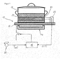
- FIG. 1 illustrates a cooking area 10 of a cooking appliance, which includes a heater 12 below a glass ceramic plate 14.
- the heating power of the electric heater 12 is adjustable via an electronic control circuit 16.
- an infrared sensor 22 is provided which detects a temperature on an outer wall 24 of the cookware 18 without contact.
- control circuit 16 At least two input variables are processed. These are on the one hand by the user by means of an input device 26 preselected cooking temperature, T soll . On the other hand, the control circuit detects a measurement signal supplied by the infrared sensor 22.
- the infrared sensor 22 preferably has a multi-channel pyrometer whose electrical output signals S (T) are evaluated in the control circuit 16 and from which a compensation is calculated, so that the temperatures of the food can be reliably determined even with different materials 18 of the cookware 18.
- FIG. 2 illustrates a qualitative relationship between the output signals of the sensor at different wavelength ranges and at different temperatures of the cookware using the example of a so-called blackbody. Shown are the relationships between a heat energy emitted by the cookware at different wavelengths. On the abscissa a wavelength ⁇ in the range between 0 and 20 microns is plotted. The ordinate shows the energy emitted by the cookware (in W / cm 2 / ⁇ m) of the blackbody.
- the temperature detection of the food to be cooked in the cookware relies on previously measured specific waveforms for different materials, coatings, reflectivities, and wall thicknesses of typical cookware used in the field. From the specific signal curves can be concluded with good probability on the used cookware, after which can be derived from the temperatures of assignment rules that are stored in the control circuit.
- FIG. 3 illustrates a number of estimated signal sweeps when viewing a blackbody. These courses can be confirmed by rough calculations. In this case, it is clear that with infrared measurements in a temperature range of about 40 ° C to about 200 ° C (within a wavelength range of about 5 microns to about 16 microns) with a signal swing in the order of about 3 to 5 are expected can. While on the abscissa of the diagram the FIG. 3 a pot temperature (T pot ) is plotted in a range of 0 ° C to 200 ° C, the ordinate shows the expected signal swing SH.
- the horizontal curve describes the signal S 12 in a considered wavelength range between 8 .mu.m and 9 .mu.m
- the five inclined curves illustrate a pot-temperature dependent signal swing SH of the second observed signal S 34 at different wavelength ranges. From these relationships, relatively precise conclusions can be drawn with regard to the material under consideration, so that in reality the temperature sensor supplies a material-dependent signal, which is converted in the downstream evaluation unit into a material-independent temperature signal.
- the limitation of the detected wavelength ranges to approximately 5 to 15 ⁇ m is sufficient in practice to allow a relatively precise temperature control.
- the simultaneous detection of three wavelength ranges significantly increases the quality of control over the detection of only two ranges.
- the detection of four or more areas can significantly improve the quality of the temperature control again.
Description
Die vorliegende Erfindung betrifft einen Temperatursensor für ein Gargerät gemäß Oberbegriff des Anspruchs 1, der zur berührungslosen Erfassung einer Temperatur eines Kochgeschirrs dient. Die Erfindung betrifft zudem ein Gargerät mit den Merkmalen des Anspruchs 2 sowie ein Verfahren zur berührungslosen Erfassung einer Temperatur eines Kochgeschirrs mit den Merkmalen des Anspruchs 3.The present invention relates to a temperature sensor for a cooking appliance according to the preamble of
Einfacher ausgestattete Gargeräte weisen keine Schaltungen zur Regelung einer Gartemperatur auf. Die Gartemperatur kann lediglich grob mittels Stelleinrichtungen vorgewählt werden. Während des Garverlaufs schwankt dann die Temperatur an der Kochstelle mehr oder weniger stark. Bei besser ausgestatteten Gargeräten kann eine Regelungsschaltung vorgesehen sein, die zur Konstanthaltung einer vorgewählten Temperatur dient. Eine notwendige Eingangsgröße stellt eine gemessene Temperatur am Kochfeld und/oder am Kochgeschirr dar.Simplified cooking appliances have no circuits for controlling a cooking temperature. The cooking temperature can only be roughly preselected by means of adjusting devices. During the course of cooking, the temperature at the hotplate fluctuates more or less. In better equipped cooking appliances, a control circuit may be provided which serves to keep constant a preselected temperature. A necessary input is a measured temperature on the hob and / or on the cookware.
Bekannte, berührungslos arbeitende Temperatursensoren dienen bei Gargeräten zur Erfassung der Temperaturen der auf den Kochfeldern befindlichen Kochgeschirre. Bekannte Temperatursensoren umfassen einen Infrarotsensor, der mittels eines Gleichlichtpyrometers die Temperatur der Außenwand des Kochgeschirrs in einem Wellenlängenbereich von ca. 6 µm bis ca. 14 µm erfasst. Das vom Infrarotsensor für die elektronische Regelung bereit gestellte elektrische Signal hängt unmittelbar vom Emissionsgrad der betrachteten Topfseite ab. Damit ein möglichst zuverlässiges und störungsfreies Signal erreicht wird, muss dieser Emissionsgrad im betrachteten Wellenlängenbereich möglichst exakt bekannt sein. Dieser betrachtete Wellenlängenbereich wird auch als Bandemissionsgrad bezeichnet.Known, non-contact temperature sensors used in cooking appliances for detecting the temperatures of the cooking hobs located on the hobs. Known temperature sensors include an infrared sensor, which detects the temperature of the outer wall of the cookware in a wavelength range of about 6 microns to about 14 microns by means of a Gleichlichtpyrometers. The electrical signal provided by the infrared sensor for the electronic control depends directly on the emissivity of the considered pot side. In order to achieve the most reliable and trouble-free signal, this emissivity must be known as accurately as possible in the considered wavelength range. This considered wavelength range is also referred to as band emissivity.
Allerdings differieren die Emissionsgrade unterschiedlicher Kochgeschirre aufgrund der teilweise unterschiedlichen Materialien. Der Emissionsgrad von Edelstahltöpfen unterscheidet sich stark von dem Emissionsgrad emaillierter Töpfe. Bereits der Einsatz von Töpfen mit ungeeigneter Emailbeschichtung führt zu einer Verschiebung der erreichten Lebensmitteltemperaturen im Topf. Ursache hierfür sind Schwankungen des Bandemissionsgrades der Emailbeschichtung. Bereits Verschmutzungen auf der Beschichtung können Probleme bei der exakten Temperaturbestimmung bereiten.However, the emissivities of different cookware differ due to the partially different materials. The emissivity of stainless steel pots differs greatly from the emissivity of enamelled pots. Even the use of pots with unsuitable enamel coating leads to a shift in the reached food temperatures in the pot. This is due to fluctuations in the band emissivity of the enamel coating. Already soiling on the coating can cause problems in the exact temperature determination.
Ein Verfahren zur berührungslosen, vom Emissionsgrad des betrachteten Objekts unabhängigen Strahlungsmessung der Objekttemperatur ist aus der
Aus der
Eine Aufgabe der vorliegenden Erfindung besteht darin, einen berührungslos arbeitenden Sensor zur Erfassung einer Kochgeschirrtemperatur zur Verfügung zu stellen, der ein möglichst zuverlässiges Temperatursignal liefert.An object of the present invention is to provide a non-contact sensor for detecting a cookware temperature, which provides a reliable temperature signal as possible.
Diese Aufgabe wird durch die Merkmale des Anspruchs 1 und respektive Anspruchs 3 gelöst.This object is solved by the features of
Dabei erfasst ein Infrarotsensor in einem definierten Wellenlängenbereich λ (mit λ1 ≤ λ ≤ λ2) die vom betrachteten Objekt ausgehende Wärmestrahlung und wandelt diese in ein elektrisches Signal um. Das vom Infrarotsensor gelieferte elektrische Signal S12(T) bezeichnet eindeutig die Temperatur der betrachteten Oberfläche. Der Bandemissionsgrad ε12 der betrachteten Oberfläche ist in dem erfassten Signal S12(T) als multiplikativer Faktor enthalten. Das Signal S12(T) kann entsprechend folgender Gleichung (1) hergeleitet werden ![]()
![]()
Unter der Voraussetzung, dass in zwei getrennten Wellenlängenbereichen λ1 ≤ λ ≤ λ2 und λ3 ≤ λ ≤ λ4 (mit λ2 < λ3) die beiden jeweiligen Bandemissionsgrade ε12 und ε34 ungefähr gleich groß sind, kann aus der obigen Gleichung (1) aus den Ausgangssignalen ein Verhältnis der beiden Signale S12(T) und S34(T) entsprechend folgender Gleichung (2) gebildet werden. 
Hieraus lässt sich auf relativ zuverlässige Weise eine tatsächliche Temperatur der betrachteten Objektfläche ermitteln, auch wenn die Bandemissionsgrade unterschiedlich groß sind. Da zudem die beiden Faktoren, welche von den jeweils benutzten Optiken und den Größen der betrachteten Flächen abhängen, bekannt sind, reduziert sich die Gleichung (2) zur folgenden Gleichung (3): ![]()
![]()
In dieser Gleichung (3) ist der Faktor COptik nur noch als allgemeiner Faktor enthalten, welcher die speziellen Eigenheiten der beiden Pyrometerkanäle beschreibt. Der errechnete Wert S12/34(T) ist ein relativ zuverlässiges Maß für die Temperatur der betrachteten Fläche. Die Erfindung ermöglicht somit eine materialunabhängige Erfassung der Kochtemperaturen. Hierbei gibt es keine Probleme mit schwankenden Emailqualitäten oder mit unterschiedlichen Materialen der verwendeten Kochgeschirre, da die verwendete Infrarotkochsensorik unabhängig von der Art des eingesetzten Kochgeschirrs ist.In this equation (3), the factor C optics is only included as a general factor, which describes the special characteristics of the two pyrometer channels. The calculated value S 12/34 (T) is a relatively reliable measure of the temperature of the considered area. The invention thus enables a material-independent detection of the cooking temperatures. There are no problems with fluctuating qualities of enamel or with different materials of the cookware used, since the infrared cooking sensor used is independent of the type of cookware used.
Wenn die beiden Bandemissionsgrade ε12 und ε34 nicht gleich sind, dann kann mit der folgenden Gleichung (4) ![]()
![]()
![]()
![]()
Falls die mit diesen Gleichungen erreichte Genauigkeit nicht ausreichen sollte, können wahlweise auch mehr als zwei Wellenlängenbereiche betrachtet werden. Durch Betrachtung von mindestens drei getrennten Wellenlängenbereichen λ1 ≤ λ ≤ λ2 , λ3 ≤ λ ≤ λ4 und λ5 ≤ λ ≤ λ6 (mit λ2 < λ3 und λ4 < λ5) kann die Messgenauigkeit erhöht und zudem die Zulässigkeit einer Rechung nach Gleichung (3) überprüft werden. Ggf. ist es sogar möglich, das Verhältnis der betrachteten Bandemissionsgrade abzuschätzen. Die Güte einer solchen Abschätzung kann im betrachteten Anwendungsfall sehr genaue Werte für die zu erfassenden Temperaturen liefern, da die Anzahl der eingesetzten unterschiedlichen Kochgeschirre nicht unbegrenzt ist. In der Regel wird die Kochsensorik nur mit einer sehr begrenzten Anzahl unterschiedlicher Materialien von Kochgeschirren konfrontiert.If the accuracy achieved with these equations is not sufficient, then optionally more than two wavelength ranges can be considered. By considering at least three separate wavelength ranges λ 1 ≦ λ ≦ λ 2 , λ 3 ≦ λ ≦ λ 4 and λ 5 ≦ λ ≦ λ 6 (with λ 2 <λ 3 and λ 4 <λ 5 ), the measurement accuracy can be increased and also the admissibility of a calculation is examined in accordance with equation (3). Possibly. it is even possible to estimate the ratio of the observed band emissivities. The quality of such an estimate can provide very accurate values for the temperatures to be detected in the application considered, since the number of different cooking utensils used is not unlimited. In general, the cooking sensor is confronted with only a very limited number of different materials of cookware.
Für eine relativ präzise Temperaturregelung ist es erfindungsgemäss vorgesehen, dass sich die einzelnen Wellenlängenbereiche nicht überschneiden, sondern voneinander beabstandet sind. Dabei ist es für eine zuverlässige Aussage über die Temperatur entscheidend, dass die den Wellenlängenbereichen zugeordneten Energiemengen im wesentlichen gleichgroß sind.
Für eine besonders genaue Berechnung der Temperatur ist vorgesehen, dass die Wellenlängenbereiche eine Breite von zumindest 5 bis 2 µm, insbesondere eine Breite von 10 µm bis 20 µm aufweisen. In der Praxis hat sich gezeigt, dass eine Beschränkung der erfassten Wellenlängenbereiche auf 15 µm bis 20 µm ausreicht, um eine relative präzise Temperaturregelung zu ermöglichen. Hierbei ist es für eine möglichst fehlerfreie Temperaturermittlung besonders vorteilhaft, wenn einerseits die einzelnen Wellenlängenbereiche von möglichst gleicher Breite sind und gleichzeitig aneinander stoßen.For a relatively precise temperature control, it is provided according to the invention that the individual wavelength ranges do not overlap, but are spaced apart from one another. It is crucial for a reliable statement about the temperature that the energy levels associated with the wavelength ranges are substantially the same.
For a particularly accurate calculation of the temperature, it is provided that the wavelength ranges have a width of at least 5 to 2 μm, in particular a width of 10 μm to 20 μm. In practice, it has been shown that a Limiting the detected wavelength ranges to 15 microns to 20 microns sufficient to allow a relatively precise temperature control. Here, it is particularly advantageous for the most error-free temperature determination, if on the one hand the individual Wavelength ranges of the same width as possible and abut each other at the same time.
Die Erfindung betrifft weiterhin ein Gargerät mit wenigstens einer Kochstelle, die eine elektronische Temperaturregelung aufweist, deren wenigstens eine Regelgröße mittels eines Temperatursensors gemäß einer der zuvor beschriebenen Ausführungsformen ermittelbar ist. Die sinnvollen Wellenlängenbereiche für das Mehrkanalpyrometer des Temperatursensors können zwischen 4 und 20 µm liegen. Vorzugsweise weist der Kochsensor ein Mehrkanalpyrometer mit mindestens drei Messwellenlängenbereichen auf. Gegebenenfalls können auch mehr Kanäle vorgesehen sein.The invention further relates to a cooking appliance having at least one cooking station, which has an electronic temperature control, whose at least one controlled variable can be determined by means of a temperature sensor according to one of the embodiments described above. The reasonable wavelength ranges for the multi-channel pyrometer of the temperature sensor can be between 4 and 20 microns. Preferably, the cooking sensor has a multi-channel pyrometer with at least three measuring wavelength ranges. Optionally, more channels may be provided.
Die Erfindung betrifft schließlich ein Verfahren zur berührungslosen Erfassung einer Temperatur eines Kochgeschirrs, bei dem mittels eines Infrarotsensors wenigstens zwei unterschiedliche, vom Kochgeschirr emittierte, Wellenlängenbereiche erfasst werden.Finally, the invention relates to a method for the non-contact detection of a temperature of a cookware in which at least two different wavelength ranges emitted by the cookware are detected by means of an infrared sensor.
Der Vorteil der erfindungsgemäßen Sensorik liegt darin, dass keine Probleme mit schwankenden Emailqualitäten, mit unterschiedlichen Materialien, mit unterschiedlichen Vorschäden an den Kochgeschirren, etc. mehr auftreten. Die Kochsensorik ist relativ unabhängig von der Art des eingesetzten Kochgeschirrs.The advantage of the sensor technology according to the invention is that no problems with fluctuating qualities of enamel, with different materials, with different previous damage to the cookware, etc. occur more. The cooking sensor is relatively independent of the type of cookware used.
Weiter Ausgestaltungen und Vorteile der Erfindung lassen sich den abhängigen Ansprüchen entnehmen.Further embodiments and advantages of the invention can be taken from the dependent claims.
Die Erfindung wird nachfolgend anhand eines bevorzugten Ausführungsbeispiels unter Bezugnahme auf die beiliegenden Zeichnungen näher erläutert. Dabei zeigt:
Figur 1- eine schematische Darstellung einer Kochstelle mit einem erfindungsgemäßen Temperatursensor,
- Figur 2
- in einem Diagramm einen Zusammenhang zwischen einer Temperatur eines Kochgeschirrs und einer von diesem emittierten Strahlungsenergie und
- Figur 3
- in einem weiteren Diagramm unterschiedliche Signalhubverläufe eines Schwarzen Strahlers bei unterschiedlichen Temperaturen bzw. Wellenlängenbereichen.
- FIG. 1
- a schematic representation of a cooking area with a temperature sensor according to the invention,
- FIG. 2
- in a diagram, a relationship between a temperature of a cookware and a radiant energy emitted by this and
- FIG. 3
- in a further diagram different Signalhubverläufe a black body at different temperatures or wavelength ranges.
In der Regelschaltung 16 werden zumindest zwei Eingangsgrößen verarbeitet. Dies sind zum einen eine vom Benutzer mittels einer Eingabeeinrichtung 26 vorgewählte Kochtemperatur, Tsoll. Zum anderen erfasst die Regelschaltung ein vom Infrarotsensor 22 geliefertes Messsignal. Der Infrarotsensor 22 weist vorzugsweise ein Mehrkanalpyrometer auf, dessen elektrische Ausgangssignale S(T) in der Regelschaltung 16 ausgewertet werden und woraus eine Kompensation errechnet wird, so dass die Temperaturen des Garguts 20 auch bei unterschiedlichen Materialien des Kochgeschirrs 18 zuverlässig bestimmt werden können.In the
Das Diagramm der
Es ist deutlich erkennbar, dass bei einer Temperatur des Kochgeschirrs von ca. 40 °C (TTopf ≈ 40 °C) keine verwertbaren Aussagen über die bei unterschiedlichen Wellenlängen abgestrahlte Wärmeenergie gemacht werden können. Bei einer erhöhten Temperatur des Kochgeschirrs von ca. 250 °C (TTopf ≈ 250 °C) tritt jedoch ein spezifisches Energiemaximum im betrachteten Wellenlängenbereich zwischen 5 µm (λ1) und 7 µm (λ2) auf, woraus ein Signal S12 gewonnen werden kann. Ebenso kann ein verwertbares Signal S34 im betrachteten weiteren Wellenlängenbereich zwischen 9 µm (λ3) und 11 µm (λ4) gewonnen werden, woraus mit Hilfe der oben dargestellten Gleichungen (1) bis (5) mit relativ guter Genauigkeit einer wahrscheinliche Temperatur des Kochgeschirrs hergeleitet werden kann.It can be clearly seen that at a temperature of the cookware of about 40 ° C (T pot ≈ 40 ° C) no usable information about the thermal energy radiated at different wavelengths can be made. At an elevated temperature of the cookware of about 250 ° C (T pot ≈ 250 ° C), however, occurs a specific Energy maximum in the considered wavelength range between 5 microns (λ 1 ) and 7 microns (λ 2 ), from which a signal S 12 can be obtained. Similarly, a usable signal S 34 in the other wavelength range considered between 9 microns (λ 3 ) and 11 microns (λ 4 ) are obtained, from which with the aid of the above equations (1) to (5) with relatively good accuracy of a probable temperature of Cookware can be derived.
Die Temperaturerfassung der im Kochgeschirr zu garenden Speisen beruht auf zuvor gemessenen spezifischen Signalverläufen für unterschiedliche Materialen, Beschichtungen, Reflexionsgraden und Wandstärken von typischerweise in der Praxis verwendeten Kochgeschirren. Aus den spezifischen Signalverläufen kann mit guter Wahrscheinlichkeit auf das verwendete Kochgeschirr geschlossen werden, wonach sich dessen Temperaturen aus Zuordnungsvorschriften, die in der Regelschaltung abgelegt sind, herleiten lassen.The temperature detection of the food to be cooked in the cookware relies on previously measured specific waveforms for different materials, coatings, reflectivities, and wall thicknesses of typical cookware used in the field. From the specific signal curves can be concluded with good probability on the used cookware, after which can be derived from the temperatures of assignment rules that are stored in the control circuit.
Das Diagramm der
Die Beschränkung der erfassten Wellenlängenbereiche auf ca. 5 bis 15 µm reicht in der Praxis aus, um eine relativ präzise Temperaturregelung zu ermöglichen. Die gleichzeitige Erfassung von drei Wellenlängenbereichen erhöht die Regelgüte gegenüber der Erfassung von nur zwei Bereichen deutlich. Die Erfassung von vier oder mehr Bereichen kann die Güte der Temperaturregelung nochmals deutlich verbessern.The limitation of the detected wavelength ranges to approximately 5 to 15 μm is sufficient in practice to allow a relatively precise temperature control. The simultaneous detection of three wavelength ranges significantly increases the quality of control over the detection of only two ranges. The detection of four or more areas can significantly improve the quality of the temperature control again.
- 1010
- Kochstellecooking
- 1212
- Heizeinrichtungheater
- 1414
- GlaskeramikplatteGlass ceramic plate
- 1616
- Regelschaltungcontrol circuit
- 1818
- KochgeschirrCookware
- 2020
- Gargutbe cooked
- 2222
- Infrarotsensorinfrared sensor
- 2424
- Außenwandouter wall
- 2626
- Eingabeeinrichtunginput device
Claims (5)
- Temperature sensor of a cooking appliance for contactlessly acquiring a temperature of a cooking utensil (18), which has at least one infrared sensor (22), wherein the at least one infrared sensor (22) has a multi-channel pyrometer with at least two sensitivity ranges varying from one another for acquiring at least two different wavelength ranges emitted by the cooking utensil (18), which are spaced apart from one another, characterised in that the wavelength ranges have a width of at least 5 to 2 µm, wherein the same thermal energy quantities are essentially assigned to each of the wavelength ranges.
- Cooking appliance with at least one hob (10), which has an electronic temperature regulator, the at least one variable of which can be determined by means of a temperature sensor according to claim 1, wherein the temperature sensor of the cooking appliance is arranged on the hob (10) in close proximity to the cooking utensil (18).
- Method for contactlessly acquiring a temperature of a cooking utensil (18), in which at least two different wavelength ranges emitted by the cooking utensil (18) are acquired by means of an infrared sensor (22) having a multi-channel pyrometer, in which the wavelengths acquired by the infrared sensor (22) lie in a range between approx. 4 µm to 20 µm, wherein the at least two different wavelength ranges have a width of at least 5 to 2 µm and are spaced apart from one another, wherein the same thermal energy quantities are essentially assigned to each of the wavelength ranges, and in which method the temperature of the cooking utensil (18) is determined from the signals for the different wavelength ranges.
- Method according to claim 3, in which the infrared sensor (22) acquires at least three different wavelength ranges.
- Method according to claim 3 or 4, in which different materials of the cooking utensil (18) are taken into consideration when determining the temperature of different band emission rates (ε).
Priority Applications (2)
| Application Number | Priority Date | Filing Date | Title |
|---|---|---|---|
| SI200532233T SI1747435T1 (en) | 2004-05-13 | 2005-05-13 | Temperature sensor for a cooking device, cooking device with electronic temperature control and method for temperature recording |
| PL05747186T PL1747435T3 (en) | 2004-05-13 | 2005-05-13 | Temperature sensor for a cooking device, cooking device with electronic temperature control and method for temperature recording |
Applications Claiming Priority (2)
| Application Number | Priority Date | Filing Date | Title |
|---|---|---|---|
| DE102004023846A DE102004023846A1 (en) | 2004-05-13 | 2004-05-13 | Temperature sensor for a cooking appliance, cooking appliance with electronic temperature control and method for temperature detection |
| PCT/EP2005/052199 WO2005111561A1 (en) | 2004-05-13 | 2005-05-13 | Temperature sensor for a cooking device, cooking device with electronic temperature control and method for temperature recording |
Publications (2)
| Publication Number | Publication Date |
|---|---|
| EP1747435A1 EP1747435A1 (en) | 2007-01-31 |
| EP1747435B1 true EP1747435B1 (en) | 2018-09-26 |
Family
ID=34968202
Family Applications (1)
| Application Number | Title | Priority Date | Filing Date |
|---|---|---|---|
| EP05747186.4A Active EP1747435B1 (en) | 2004-05-13 | 2005-05-13 | Temperature sensor for a cooking device, cooking device with electronic temperature control and method for temperature recording |
Country Status (7)
| Country | Link |
|---|---|
| US (1) | US20070214967A1 (en) |
| EP (1) | EP1747435B1 (en) |
| DE (1) | DE102004023846A1 (en) |
| PL (1) | PL1747435T3 (en) |
| RU (1) | RU2006138680A (en) |
| SI (1) | SI1747435T1 (en) |
| WO (1) | WO2005111561A1 (en) |
Families Citing this family (15)
| Publication number | Priority date | Publication date | Assignee | Title |
|---|---|---|---|---|
| DE102006023190A1 (en) * | 2006-05-17 | 2007-11-22 | BSH Bosch und Siemens Hausgeräte GmbH | Temperature sensing device |
| DE102007013839A1 (en) * | 2007-03-22 | 2008-09-25 | BSH Bosch und Siemens Hausgeräte GmbH | Cooking field sensor device for collection of parameter of cooking utensil by radiation, for cooking field, has sensor unit, which is assigned to spectral range of radiation, and optical unit that is provided to upstream sensor unit |
| CN201404073Y (en) * | 2009-04-28 | 2010-02-17 | 漳州灿坤实业有限公司 | Wireless temperature transmission type electric kettle |
| US8931400B1 (en) * | 2009-05-28 | 2015-01-13 | iDevices. LLC | Remote cooking systems and methods |
| DE102009036089A1 (en) * | 2009-08-04 | 2011-02-17 | Wmf Württembergische Metallwarenfabrik Ag | Device for storing milk |
| DE102011081303A1 (en) * | 2011-08-22 | 2013-02-28 | BSH Bosch und Siemens Hausgeräte GmbH | Monitoring device for hobs |
| EP2798910B1 (en) * | 2011-12-29 | 2017-06-21 | Arçelik Anonim Sirketi | A wireless kitchen appliance operated on an induction heating cooker |
| JP5894682B2 (en) | 2011-12-29 | 2016-03-30 | アルチュリク・アノニム・シルケチ | Wireless kitchen utensils operated on induction cooker |
| US10182472B2 (en) | 2011-12-29 | 2019-01-15 | Arcelik Anonim Sirketi | Wireless kitchen appliance operated on induction heating cooker |
| DE102016205005A1 (en) * | 2016-03-24 | 2017-09-28 | BSH Hausgeräte GmbH | Cooking device with calibration function |
| CN107289470B (en) * | 2016-04-11 | 2019-06-14 | 众智光电科技股份有限公司 | Gas oven with temperature sensing function |
| CN107773022B (en) * | 2016-08-30 | 2023-10-13 | 浙江苏泊尔家电制造有限公司 | Cooking utensil |
| WO2019124129A1 (en) * | 2017-12-18 | 2019-06-27 | パナソニックIpマネジメント株式会社 | Temperature detecting device and induction heating device |
| FI20185482A1 (en) * | 2018-05-25 | 2019-11-26 | Safera Oy | Stove guard that makes use of different wavelengths |
| DE102019211292A1 (en) * | 2019-07-30 | 2021-02-04 | BSH Hausgeräte GmbH | Device and method for determining the temperature of the contents of a container |
Family Cites Families (14)
| Publication number | Priority date | Publication date | Assignee | Title |
|---|---|---|---|---|
| DE3036638C2 (en) * | 1980-09-29 | 1983-11-03 | Vanzetti Infrared & Computer Systems, Inc., Canton, Mass. | Band ratio radiometer |
| DE3044735C2 (en) * | 1980-11-27 | 1984-05-17 | Dmitrij Evgen'evič Egorov | Color pyrometer |
| DE3341234C1 (en) * | 1983-11-15 | 1985-05-15 | Kurt Wolf & Co Kg, 7547 Wildbad | Arrangement for measuring the temperature in a heating system consisting of a hot plate and a saucepan |
| EP0143282B1 (en) * | 1983-11-28 | 1989-02-01 | Deutsches Zentrum für Luft- und Raumfahrt e.V | Method for the contactless, emissivity-independent radiation measurement of the temperature of an object |
| DD254114A3 (en) * | 1985-07-30 | 1988-02-17 | Univ Dresden Tech | PYROMETRIC MEASURING PROCEDURE |
| FR2663740B1 (en) * | 1990-06-21 | 1992-09-11 | Commissariat Energie Atomique | PROCESS FOR EXPLOITING SIGNALS PROVIDED BY AN OPTICAL PYROMETER, PARTICULARLY FOR MEASURING ACCURATELY THE TEMPERATURE OF MOVING BODY AND AT RAPIDLY EVOLUTIVE TEMPERATURE. |
| CH685405A5 (en) * | 1992-10-06 | 1995-06-30 | Alusuisse Lonza Services Ag | Temperature measurement with Zweiwellenlängenpyrometern. |
| KR940703996A (en) * | 1992-11-03 | 1994-12-12 | 알.밴 오버스트래텐 | Method for adjusting heating of object in heating chamber and system (System For The Controlled Heating Of An Object) |
| DE4342489C2 (en) * | 1993-12-13 | 1998-10-22 | Heiko Katzer | Circuit arrangement for recording temperatures of a cooking vessel |
| DE19721475A1 (en) * | 1997-05-23 | 1998-11-26 | Eko Stahl Gmbh | Process for non-contact temperature measurement |
| US6375350B1 (en) * | 2000-08-08 | 2002-04-23 | Quantum Logic Corp | Range pyrometer |
| JP2003121266A (en) * | 2001-10-11 | 2003-04-23 | Noritake Co Ltd | Method and instrument for measuring temperature |
| US6872945B2 (en) * | 2002-11-08 | 2005-03-29 | General Electric Company | Apparatus and method for detection of railroad wheel and bearing temperature |
| DE10329205A1 (en) * | 2003-06-28 | 2005-01-27 | Infineon Technologies Ag | Contactless measurement of the surface temperature of a semiconductor wafer by measuring the surface radiating intensity at two wavelengths having the same emission ratio and then formation of their quotient |
-
2004
- 2004-05-13 DE DE102004023846A patent/DE102004023846A1/en not_active Withdrawn
-
2005
- 2005-05-13 US US11/587,561 patent/US20070214967A1/en not_active Abandoned
- 2005-05-13 EP EP05747186.4A patent/EP1747435B1/en active Active
- 2005-05-13 PL PL05747186T patent/PL1747435T3/en unknown
- 2005-05-13 RU RU2006138680/28A patent/RU2006138680A/en not_active Application Discontinuation
- 2005-05-13 SI SI200532233T patent/SI1747435T1/en unknown
- 2005-05-13 WO PCT/EP2005/052199 patent/WO2005111561A1/en active Application Filing
Non-Patent Citations (1)
| Title |
|---|
| None * |
Also Published As
| Publication number | Publication date |
|---|---|
| RU2006138680A (en) | 2008-06-20 |
| EP1747435A1 (en) | 2007-01-31 |
| US20070214967A1 (en) | 2007-09-20 |
| DE102004023846A1 (en) | 2005-12-08 |
| SI1747435T1 (en) | 2018-11-30 |
| PL1747435T3 (en) | 2019-03-29 |
| WO2005111561A1 (en) | 2005-11-24 |
Similar Documents
| Publication | Publication Date | Title |
|---|---|---|
| EP1747435B1 (en) | Temperature sensor for a cooking device, cooking device with electronic temperature control and method for temperature recording | |
| DE3129139C2 (en) | Device for measuring the surface temperature of an object in an oven | |
| EP1718998B1 (en) | Method and measuring instrument for locating objects enclosed in a medium | |
| DE602005005762T2 (en) | Method and system for thickness measurement of an oxide layer | |
| DE3108153A1 (en) | METHOD AND DEVICE FOR MEASURING THE SURFACE TEMPERATURE AND THE EMISSION CAPACITY OF HEATED MATERIAL | |
| DE2262737B2 (en) | Method and device for measuring the surface temperature of a metal object | |
| EP2813129B1 (en) | Induction cooking hob having an inductor coil field | |
| EP1865754A2 (en) | Induction cooking hob and method for determining the temperature of the base of a cooking container | |
| EP1615469A2 (en) | Cooking apparatus with temperature detection and method for detecting temperature in a cooking apparatus | |
| EP2825859B1 (en) | Device for determining the temperature of a substrate | |
| WO2008064898A1 (en) | Method for generating processing and analysing a signal correlated to temperature and corresponding device | |
| DE60305359T2 (en) | A method of calculating contact thermal resistance in a differential scanning calorimeter | |
| DE19832833C2 (en) | Process for thermographic examination of a workpiece and device therefor | |
| EP1789764B1 (en) | Radiation measuring apparatus, and method and device for testing proper functioning of said radiation measuring apparatus | |
| EP0697102B1 (en) | Calibration of high-temperature thermocouples | |
| EP0967839A2 (en) | Cooking plate with operating unit determining its power level | |
| DE60025662T2 (en) | radiation thermometer | |
| DE2036247A1 (en) | Temperature control device for an electric heating device | |
| EP2163823B1 (en) | Cooking sensor for a cooking device | |
| EP3258742A1 (en) | Method for operating a cooking device and cooking device | |
| EP0772991A1 (en) | Sensor controlled cooking unit | |
| DE60313181T2 (en) | METHOD AND DEVICE FOR DETERMINING A PHASE TRANSITION OF A SUBSTANCE | |
| DE4143602C2 (en) | Thermal conductivity measuring appts. | |
| DE4134313A1 (en) | Contactless infrared temp. measurement of body conducting heat - measuring infrared radiation emanating from body in two separate wavelength regions to determine surface and internal temp. | |
| DE2153077A1 (en) | METHOD FOR CONTACTLESS MEASUREMENT OF SURFACE TEMPERATURE ON AN OBJECT |
Legal Events
| Date | Code | Title | Description |
|---|---|---|---|
| PUAI | Public reference made under article 153(3) epc to a published international application that has entered the european phase |
Free format text: ORIGINAL CODE: 0009012 |
|
| 17P | Request for examination filed |
Effective date: 20061213 |
|
| AK | Designated contracting states |
Kind code of ref document: A1 Designated state(s): AT BE BG CH CY CZ DE DK EE ES FI FR GB GR HU IE IS IT LI LT LU MC NL PL PT RO SE SI SK TR |
|
| 17Q | First examination report despatched |
Effective date: 20070326 |
|
| DAX | Request for extension of the european patent (deleted) | ||
| RAP1 | Party data changed (applicant data changed or rights of an application transferred) |
Owner name: BSH HAUSGERAETE GMBH |
|
| STAA | Information on the status of an ep patent application or granted ep patent |
Free format text: STATUS: EXAMINATION IS IN PROGRESS |
|
| GRAP | Despatch of communication of intention to grant a patent |
Free format text: ORIGINAL CODE: EPIDOSNIGR1 |
|
| STAA | Information on the status of an ep patent application or granted ep patent |
Free format text: STATUS: GRANT OF PATENT IS INTENDED |
|
| INTG | Intention to grant announced |
Effective date: 20180509 |
|
| GRAS | Grant fee paid |
Free format text: ORIGINAL CODE: EPIDOSNIGR3 |
|
| GRAA | (expected) grant |
Free format text: ORIGINAL CODE: 0009210 |
|
| STAA | Information on the status of an ep patent application or granted ep patent |
Free format text: STATUS: THE PATENT HAS BEEN GRANTED |
|
| AK | Designated contracting states |
Kind code of ref document: B1 Designated state(s): AT BE BG CH CY CZ DE DK EE ES FI FR GB GR HU IE IS IT LI LT LU MC NL PL PT RO SE SI SK TR |
|
| REG | Reference to a national code |
Ref country code: GB Ref legal event code: FG4D Free format text: NOT ENGLISH |
|
| REG | Reference to a national code |
Ref country code: CH Ref legal event code: EP |
|
| REG | Reference to a national code |
Ref country code: AT Ref legal event code: REF Ref document number: 1046572 Country of ref document: AT Kind code of ref document: T Effective date: 20181015 |
|
| REG | Reference to a national code |
Ref country code: IE Ref legal event code: FG4D Free format text: LANGUAGE OF EP DOCUMENT: GERMAN |
|
| REG | Reference to a national code |
Ref country code: DE Ref legal event code: R096 Ref document number: 502005015917 Country of ref document: DE |
|
| REG | Reference to a national code |
Ref country code: NL Ref legal event code: MP Effective date: 20180926 |
|
| PG25 | Lapsed in a contracting state [announced via postgrant information from national office to epo] |
Ref country code: GR Free format text: LAPSE BECAUSE OF FAILURE TO SUBMIT A TRANSLATION OF THE DESCRIPTION OR TO PAY THE FEE WITHIN THE PRESCRIBED TIME-LIMIT Effective date: 20181227 Ref country code: LT Free format text: LAPSE BECAUSE OF FAILURE TO SUBMIT A TRANSLATION OF THE DESCRIPTION OR TO PAY THE FEE WITHIN THE PRESCRIBED TIME-LIMIT Effective date: 20180926 Ref country code: FI Free format text: LAPSE BECAUSE OF FAILURE TO SUBMIT A TRANSLATION OF THE DESCRIPTION OR TO PAY THE FEE WITHIN THE PRESCRIBED TIME-LIMIT Effective date: 20180926 Ref country code: SE Free format text: LAPSE BECAUSE OF FAILURE TO SUBMIT A TRANSLATION OF THE DESCRIPTION OR TO PAY THE FEE WITHIN THE PRESCRIBED TIME-LIMIT Effective date: 20180926 Ref country code: BG Free format text: LAPSE BECAUSE OF FAILURE TO SUBMIT A TRANSLATION OF THE DESCRIPTION OR TO PAY THE FEE WITHIN THE PRESCRIBED TIME-LIMIT Effective date: 20181226 |
|
| REG | Reference to a national code |
Ref country code: LT Ref legal event code: MG4D |
|
| PG25 | Lapsed in a contracting state [announced via postgrant information from national office to epo] |
Ref country code: IT Free format text: LAPSE BECAUSE OF FAILURE TO SUBMIT A TRANSLATION OF THE DESCRIPTION OR TO PAY THE FEE WITHIN THE PRESCRIBED TIME-LIMIT Effective date: 20180926 Ref country code: EE Free format text: LAPSE BECAUSE OF FAILURE TO SUBMIT A TRANSLATION OF THE DESCRIPTION OR TO PAY THE FEE WITHIN THE PRESCRIBED TIME-LIMIT Effective date: 20180926 Ref country code: NL Free format text: LAPSE BECAUSE OF FAILURE TO SUBMIT A TRANSLATION OF THE DESCRIPTION OR TO PAY THE FEE WITHIN THE PRESCRIBED TIME-LIMIT Effective date: 20180926 Ref country code: RO Free format text: LAPSE BECAUSE OF FAILURE TO SUBMIT A TRANSLATION OF THE DESCRIPTION OR TO PAY THE FEE WITHIN THE PRESCRIBED TIME-LIMIT Effective date: 20180926 Ref country code: CZ Free format text: LAPSE BECAUSE OF FAILURE TO SUBMIT A TRANSLATION OF THE DESCRIPTION OR TO PAY THE FEE WITHIN THE PRESCRIBED TIME-LIMIT Effective date: 20180926 Ref country code: ES Free format text: LAPSE BECAUSE OF FAILURE TO SUBMIT A TRANSLATION OF THE DESCRIPTION OR TO PAY THE FEE WITHIN THE PRESCRIBED TIME-LIMIT Effective date: 20180926 Ref country code: IS Free format text: LAPSE BECAUSE OF FAILURE TO SUBMIT A TRANSLATION OF THE DESCRIPTION OR TO PAY THE FEE WITHIN THE PRESCRIBED TIME-LIMIT Effective date: 20190126 |
|
| PG25 | Lapsed in a contracting state [announced via postgrant information from national office to epo] |
Ref country code: SK Free format text: LAPSE BECAUSE OF FAILURE TO SUBMIT A TRANSLATION OF THE DESCRIPTION OR TO PAY THE FEE WITHIN THE PRESCRIBED TIME-LIMIT Effective date: 20180926 Ref country code: PT Free format text: LAPSE BECAUSE OF FAILURE TO SUBMIT A TRANSLATION OF THE DESCRIPTION OR TO PAY THE FEE WITHIN THE PRESCRIBED TIME-LIMIT Effective date: 20190126 |
|
| REG | Reference to a national code |
Ref country code: DE Ref legal event code: R097 Ref document number: 502005015917 Country of ref document: DE |
|
| PG25 | Lapsed in a contracting state [announced via postgrant information from national office to epo] |
Ref country code: DK Free format text: LAPSE BECAUSE OF FAILURE TO SUBMIT A TRANSLATION OF THE DESCRIPTION OR TO PAY THE FEE WITHIN THE PRESCRIBED TIME-LIMIT Effective date: 20180926 |
|
| PLBE | No opposition filed within time limit |
Free format text: ORIGINAL CODE: 0009261 |
|
| STAA | Information on the status of an ep patent application or granted ep patent |
Free format text: STATUS: NO OPPOSITION FILED WITHIN TIME LIMIT |
|
| 26N | No opposition filed |
Effective date: 20190627 |
|
| REG | Reference to a national code |
Ref country code: CH Ref legal event code: PL |
|
| GBPC | Gb: european patent ceased through non-payment of renewal fee |
Effective date: 20190513 |
|
| PG25 | Lapsed in a contracting state [announced via postgrant information from national office to epo] |
Ref country code: LI Free format text: LAPSE BECAUSE OF NON-PAYMENT OF DUE FEES Effective date: 20190531 Ref country code: CH Free format text: LAPSE BECAUSE OF NON-PAYMENT OF DUE FEES Effective date: 20190531 Ref country code: MC Free format text: LAPSE BECAUSE OF FAILURE TO SUBMIT A TRANSLATION OF THE DESCRIPTION OR TO PAY THE FEE WITHIN THE PRESCRIBED TIME-LIMIT Effective date: 20180926 |
|
| REG | Reference to a national code |
Ref country code: BE Ref legal event code: MM Effective date: 20190531 |
|
| PG25 | Lapsed in a contracting state [announced via postgrant information from national office to epo] |
Ref country code: LU Free format text: LAPSE BECAUSE OF NON-PAYMENT OF DUE FEES Effective date: 20190513 |
|
| PG25 | Lapsed in a contracting state [announced via postgrant information from national office to epo] |
Ref country code: GB Free format text: LAPSE BECAUSE OF NON-PAYMENT OF DUE FEES Effective date: 20190513 Ref country code: IE Free format text: LAPSE BECAUSE OF NON-PAYMENT OF DUE FEES Effective date: 20190513 |
|
| PG25 | Lapsed in a contracting state [announced via postgrant information from national office to epo] |
Ref country code: BE Free format text: LAPSE BECAUSE OF NON-PAYMENT OF DUE FEES Effective date: 20190531 |
|
| REG | Reference to a national code |
Ref country code: AT Ref legal event code: MM01 Ref document number: 1046572 Country of ref document: AT Kind code of ref document: T Effective date: 20190513 |
|
| PGFP | Annual fee paid to national office [announced via postgrant information from national office to epo] |
Ref country code: SI Payment date: 20200504 Year of fee payment: 16 Ref country code: PL Payment date: 20200504 Year of fee payment: 16 |
|
| PG25 | Lapsed in a contracting state [announced via postgrant information from national office to epo] |
Ref country code: AT Free format text: LAPSE BECAUSE OF NON-PAYMENT OF DUE FEES Effective date: 20190513 |
|
| PG25 | Lapsed in a contracting state [announced via postgrant information from national office to epo] |
Ref country code: CY Free format text: LAPSE BECAUSE OF FAILURE TO SUBMIT A TRANSLATION OF THE DESCRIPTION OR TO PAY THE FEE WITHIN THE PRESCRIBED TIME-LIMIT Effective date: 20180926 |
|
| PG25 | Lapsed in a contracting state [announced via postgrant information from national office to epo] |
Ref country code: HU Free format text: LAPSE BECAUSE OF FAILURE TO SUBMIT A TRANSLATION OF THE DESCRIPTION OR TO PAY THE FEE WITHIN THE PRESCRIBED TIME-LIMIT; INVALID AB INITIO Effective date: 20050513 |
|
| PG25 | Lapsed in a contracting state [announced via postgrant information from national office to epo] |
Ref country code: SI Free format text: LAPSE BECAUSE OF NON-PAYMENT OF DUE FEES Effective date: 20210514 |
|
| REG | Reference to a national code |
Ref country code: SI Ref legal event code: KO00 Effective date: 20220121 |
|
| PGFP | Annual fee paid to national office [announced via postgrant information from national office to epo] |
Ref country code: FR Payment date: 20220523 Year of fee payment: 18 |
|
| PGFP | Annual fee paid to national office [announced via postgrant information from national office to epo] |
Ref country code: TR Payment date: 20220512 Year of fee payment: 18 |
|
| PG25 | Lapsed in a contracting state [announced via postgrant information from national office to epo] |
Ref country code: PL Free format text: LAPSE BECAUSE OF NON-PAYMENT OF DUE FEES Effective date: 20210513 |
|
| REG | Reference to a national code |
Ref country code: DE Ref legal event code: R084 Ref document number: 502005015917 Country of ref document: DE |
|
| PGFP | Annual fee paid to national office [announced via postgrant information from national office to epo] |
Ref country code: DE Payment date: 20230531 Year of fee payment: 19 |