EP1746716A2 - Aufwärts/Abwärts-Verfahren einer Spannungsregelung für einen Permanentmagnetgenerator (PMG) - Google Patents
Aufwärts/Abwärts-Verfahren einer Spannungsregelung für einen Permanentmagnetgenerator (PMG) Download PDFInfo
- Publication number
- EP1746716A2 EP1746716A2 EP06253794A EP06253794A EP1746716A2 EP 1746716 A2 EP1746716 A2 EP 1746716A2 EP 06253794 A EP06253794 A EP 06253794A EP 06253794 A EP06253794 A EP 06253794A EP 1746716 A2 EP1746716 A2 EP 1746716A2
- Authority
- EP
- European Patent Office
- Prior art keywords
- coils
- sub
- output voltage
- voltage
- buck
- Prior art date
- Legal status (The legal status is an assumption and is not a legal conclusion. Google has not performed a legal analysis and makes no representation as to the accuracy of the status listed.)
- Granted
Links
- 230000033228 biological regulation Effects 0.000 title claims abstract description 15
- 238000000034 method Methods 0.000 title claims description 14
- 230000007423 decrease Effects 0.000 claims description 29
- 230000001276 controlling effect Effects 0.000 claims description 6
- 230000001105 regulatory effect Effects 0.000 claims description 5
- 238000012544 monitoring process Methods 0.000 claims 2
- 230000003247 decreasing effect Effects 0.000 abstract description 7
- 230000004907 flux Effects 0.000 description 46
- 230000000694 effects Effects 0.000 description 11
- 238000004804 winding Methods 0.000 description 7
- 238000010586 diagram Methods 0.000 description 6
- 230000001419 dependent effect Effects 0.000 description 2
- 238000009825 accumulation Methods 0.000 description 1
- 239000000654 additive Substances 0.000 description 1
- 230000000996 additive effect Effects 0.000 description 1
Images




Classifications
-
- H—ELECTRICITY
- H02—GENERATION; CONVERSION OR DISTRIBUTION OF ELECTRIC POWER
- H02P—CONTROL OR REGULATION OF ELECTRIC MOTORS, ELECTRIC GENERATORS OR DYNAMO-ELECTRIC CONVERTERS; CONTROLLING TRANSFORMERS, REACTORS OR CHOKE COILS
- H02P9/00—Arrangements for controlling electric generators for the purpose of obtaining a desired output
- H02P9/48—Arrangements for obtaining a constant output value at varying speed of the generator, e.g. on vehicle
-
- H—ELECTRICITY
- H02—GENERATION; CONVERSION OR DISTRIBUTION OF ELECTRIC POWER
- H02P—CONTROL OR REGULATION OF ELECTRIC MOTORS, ELECTRIC GENERATORS OR DYNAMO-ELECTRIC CONVERTERS; CONTROLLING TRANSFORMERS, REACTORS OR CHOKE COILS
- H02P2101/00—Special adaptation of control arrangements for generators
- H02P2101/30—Special adaptation of control arrangements for generators for aircraft
-
- H—ELECTRICITY
- H02—GENERATION; CONVERSION OR DISTRIBUTION OF ELECTRIC POWER
- H02P—CONTROL OR REGULATION OF ELECTRIC MOTORS, ELECTRIC GENERATORS OR DYNAMO-ELECTRIC CONVERTERS; CONTROLLING TRANSFORMERS, REACTORS OR CHOKE COILS
- H02P2201/00—Indexing scheme relating to controlling arrangements characterised by the converter used
- H02P2201/09—Boost converter, i.e. DC-DC step up converter increasing the voltage between the supply and the inverter driving the motor
-
- H—ELECTRICITY
- H02—GENERATION; CONVERSION OR DISTRIBUTION OF ELECTRIC POWER
- H02P—CONTROL OR REGULATION OF ELECTRIC MOTORS, ELECTRIC GENERATORS OR DYNAMO-ELECTRIC CONVERTERS; CONTROLLING TRANSFORMERS, REACTORS OR CHOKE COILS
- H02P2201/00—Indexing scheme relating to controlling arrangements characterised by the converter used
- H02P2201/11—Buck converter, i.e. DC-DC step down converter decreasing the voltage between the supply and the inverter driving the motor
Definitions
- a permanent magnet generator is used to convert mechanical energy, usually rotational, to electrical energy.
- the typical PMG receives mechanical energy from a prime mover.
- the prime mover may be, for example, a gas turbine engine of an aircraft.
- the prime mover causes a rotor located within the PMG to spin.
- Magnetic flux created by permanent magnets located on the rotor cause an emf voltage to be generated in stator windings.
- the accumulation of the voltage generated at each of these coils is provided as an output voltage to a load.
- the output voltage generated by the PMG is dependent, in part, on the speed of the prime mover as well as the overall impedance of the load. That is, a decrease in rotational velocity of the prime mover results in a decreased rotational velocity of the rotor, and a resulting decrease in the output voltage generated by the stator windings. An increase in rotation of the prime mover results in an increase of the output voltage generated by the coils in the stator. Likewise, a decrease in the impedance of the load results in an increase in the output voltage of the PMG, and an increase in the impedance of the load results in a decrease in the output voltage of the PMG.
- the present invention is a permanent magnet generator (PMG) system for regulating an output voltage.
- the system includes a prime mover, a PMG having a rotor connected to the prime mover, a stator having stator teeth, and stator coils wrapped around the stator teeth and divided into sub-coils.
- a buck/boost voltage is connected to selected sub-coils, wherein applying the buck/boost voltage to the selected sub-coils increases or decreases the output voltage.
- a controller monitors the output voltage and selectively applies the buck/boost voltage to the sub-coils based on the monitored output voltage.
- the present invention is a method of maintaining a constant output voltage of a permanent magnet generator.
- the method includes generating an output voltage, wherein stator coils are divided into sub-coils and selected sub-coils are connected to generate the output voltage. Variations in the output voltage are monitored, and based on the monitored output voltage, a buck/boost voltage is applied to the sub-coils not connected to generate the output voltage to either increase or decrease the output voltage.
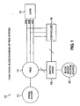
- FIG. 1 shows an embodiment of permanent magnet generator voltage regulation system 10 of the present invention, including prime mover 12, permanent magnet generator (PMG) 14, three-phase output voltage VoA, VoB, and VoC, load 16, controller 18, switch array 19, and buck/boost voltage source 20.
- Prime mover 12 is connected to PMG 14, supplying PMG 14 with rotational, mechanical energy.
- PMG 14 converts mechanical energy supplied by prime mover 12 to electrical energy, which is supplied to load 16 and is illustrated as three-phase output voltage VoA, VoB, and VoC (collectively "output voltage Vo").
- the present invention provides a system and method of maintaining a relatively constant output voltage Vo despite variations in rotational velocity of prime mover 12 and impedance of load 16.
- controller 18 monitors output voltage Vo. If a change in output voltage Vo is detected, controller 18 selectively operates a number of switches (shown in FIGS. 3, 5, and 7) located in switch array 19 to configure stator coils (shown in FIGS. 2-7) to effectively regulate output voltage Vo. Each of the stator coils is divided into two or more sub-coils. Depending on the output voltage Vo detected, controller 18 controls switches in switch array 19 to connect the sub-coils in one of many possible configurations to generate the desired output voltage. Controller 18 is also responsible for controlling when and how buck/boost voltage Vbb is applied to the sub-coils of PMG 14. Buck/boost voltage Vbb, when applied to the sub-coils, can be used as the name suggests to either buck (decrease) or boost (increase) output voltage Vo.
- buck/boost voltage is maintained at the same frequency as output voltage Vo. The reasons for this are discussed in more detail below, but without consistent frequency between buck/boost voltage and output voltage Vo, constant voltage regulation cannot be maintained.
- the buck/boost voltage is maintained in phase with output voltage Vo (boosting) or 180 degrees out of phase with output voltage Vo (bucking).
- a portion of output voltage Vo is feed back through controller 19 and switch array 20 to the sub-coils of PMG 14. This arrangement ensures that frequency of buck/boost voltage Vbb and output voltage Vo are equal.
- a second set of stator coils (not shown), in addition to the set of stator coils located within PMG 14 (shown in FIG. 2), is used to generate voltage from the mechanical energy provided by prime mover 12. As prime mover 12 rotates, stator coils within PMG 14 as well as the second set of stator coils generates voltage. Because the frequency of prime mover 12 is the same for both the set of stators located within PMG 14 and the second set of stators, the frequency of the voltage generated by PMG 14 and the second set of stator coils is equal. In both of these embodiments, buck/boost voltage Vbb is generated in phase with output voltage Vo.
- buck/boost voltage Vbb generated by one of the methods described above is delivered to the selected sub-coils in phase with output voltage Vo.
- buck/boost voltage Vbb generated by one of the methods described above is delivered to the selected sub-coils 180 degrees out of phase with output voltage Vo.
- FIG. 2 shows an embodiment of permanent magnet generator 14 of the present invention, including stator 22, rotor 24, and axis 26 connecting rotor 24 to prime mover 12 (shown in FIG. 1).
- Rotor 24 includes a plurality of poles P1-P24, making this a twenty-four pole rotor.
- Stator 22 includes a plurality of stator slots S1-S36, making this a thirty-six slot stator. Each adjacent set of slots, for instance slots S 1 and S2, form a stator tooth upon which a coil or winding is wrapped (in this case, coil CA1). Because the output of PMG 14 is three phase power, there are three electrically separate sets of coils.
- FIG. 2 shows only the set of coils CA1-CA12 responsible for output voltage VoA (shown in FIG. 1 as one of the three phases of power).
- Coil CA1 is wrapped around the stator tooth located between stator slots S1 and S2.
- Coil CA2 is wrapped around the stator tooth located between stator slots S4 and S5.
- Coil CA3 is wrapped around the stator tooth located between stator slots S7 and S8, and so on.
- coils CA1-CA12 are spaced equally around stator 22.
- each coil CA1-CA12 is exposed to equal magnitude and direction of magnetic flux generated by poles P1-P24 such that output voltage VoA is maximized.
- Two other sets of coils are wound in similar fashion around the remaining stator teeth located between slots S1-S36 to create the other two phases of power, VoB and VoC.
- each coil CA1-CA12 (as well as the coils used for generated output voltage VoB and VoC) is divided into sub-coils, which may be connected in a number of configurations to either increase or decrease output voltage Vo.
- Prime mover 12 causes rotor 24, and magnetic poles P1-P24 located on rotor 24, to spin. Voltage in the number of coils CA1-CA12 is created by the rotation of magnetic poles P1-P24, and the resulting magnetic flux seen by coils CA1-CA12.
- Each adjacent pole is necessarily of a different polarity. For instance, if magnetic pole P2 is a magnetic north pole, then both magnetic poles P1 and P3 are magnetic south poles. Magnetic flux generated by adjacent poles travels in part through the number of coils C1A-C12A (as well as those coils not shown) within stator 22.
- coils CA1-CA12 are each divided into sub-coils.
- output voltage VoA can be regulated as desired.
- Output voltage Vo generated by the number of coils is described in the following equation, assuming the output voltage is not connected to a load.
- Vo 4.44 * Frequency * #ofTurns * MagneticFlux * Area * 10 - 8
- Equation 1 illustrates the variables that affect output voltage Vo.
- Each of the variables is directly related to voltage, thus as frequency, number of turns, magnetic flux or area increase, so does output voltage 16. Likewise if any of these variables decrease, so does output voltage 16.
- Frequency is related to the speed at which prime mover 12 rotates, and area refers to the area cross section of each of the number of coils CA1-CA12.
- the frequency of the prime mover is external to PMG 14 and is not directly controlled in the present invention.
- area is also kept constant in the present invention. This leaves number of turns and magnetic flux as the remaining variable that can affect of output voltage Vo.
- Number of turns relates to the number of turns of wire making up each coil CA1-CA12.
- controller 18 selectively modifies how the sub-coils are connected. This allows controller 18 to adjust the number of turns contributing to create output voltage Vo.
- magnetic flux refers to the density of magnetic flux within each coil CA1-CA12.
- the present invention also selectively modifies the density of magnetic flux in each coil by selectively applying buck/boost voltage Vbb to the sub-coils in order to modify output voltage 16.
- FIGS. 3-7 illustrate a number of ways in which coils C1-C12, as well as their counterparts in the other two phases, can be connected to vary the output voltage generated.
- FIG. 3 shows coils CA1-CA12, each coil divided into first sub-coils CA1a-CA12a and second sub-coils CA1b-CA12b.
- coil CA1 is divided into first sub-coil CA1a and second sub-coil CA1b
- coil CA2 is divided into first sub-coil CA2a and second sub-coil CA2b.
- the number of turns of each of the plurality of first sub-coils CA1a-CA12a is equal
- the number of turns of each of the plurality of second sub-coils CA1b-CA12b is equal.
- the ratio of turns between first sub-coils CA1a-CA12a and coils CA1-CA12 is 0.6:1. That is, coils CA1-CA12 are divided such that first sub-coils CA1a-CA12a contain 60% of the turns, and second sub-coils CA1b-CA12b contain the remaining 40% of the turns. For the sake of simplicity, this embodiment shows each coil divided into two sub-coils.
- a plurality of switches SW1-SW36 allows first and second sub-coils to be connected in a number of configurations.
- switch SW1 is connected to first sub-coil CA1a
- switches SW2 and SW3 are connected to second sub-coil CA1b.
- switch SW4 is connected to first sub-coil CA2a
- switches SW5 and SW6 are connected to second sub-coil CA2b.
- Each switch SW selects between one of two possible connections.
- the connections associated with each switch SW are labeled in FIG. 3 and FIG. 5 with a "1" or a "2".
- switches SW are set to the first position labeled with a "1".
- switches SW are set to the second position labeled with a "2".
- first sub-coils CA1a-CA12a are connected in series with one another.
- first sub-coil CA1a is connected in series with first sub-coil CA2a via switch SW1.
- second sub-coils CA1b-CA12b are connected in series with one another.
- second sub-coil CA1b is connected in series with second sub-coil CA2b via switch SW3 and switch SW5.
- a buck/boost voltage source Vbb is also connected to the series of second sub-coils CA1b-CA12b.
- buck/boost voltage Vbb is connected to second sub-coil CA1b via switch SW2 and to second sub-coil CA12b via switch SW 36.
- the output voltage generated when the plurality of switches SW are in the first position is dependent on the application of buck/boost voltage Vbb.
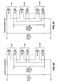
- the buck/boost voltage can be applied in three ways; no buck/boost voltage is applied (effect illustrated in FIG. 4A), buck/boost voltage applied such that magnetic flux generated in second sub-coils increases magnetic flux in first sub-coils (effect shown in FIG. 4B), and buck/boost voltage applied such that magnetic flux generated in second sub-coils decreases magnetic flux in first sub-coils (effect shown in FIG. 4C). Setting switches SW to the second position (shown in FIG.
- FIG. 4A shows the effect of applying no buck/boost voltage Vbb to the plurality of second sub-coils CA1b-CA12b. Because no buck/boost voltage Vbb is applied to the plurality of second sub-coils CA1b-CA12b connected in series with one another, no magnetic flux is generated in second sub-coils CAlb-CA12b. With no magnetic flux generated in second sub-coils CA1b-CA12b, they have no effect on the generation of output voltage created by first sub-coils CA1a-CA12a. Magnetic flux generated by the plurality of poles P1-P24 (shown in FIG. 2) crossing through first sub-coils CA1a-CA12a results in generation of voltage in each of the first sub-coils.
- output voltage VoA generated is the combined total of the voltage generated at each of the first sub-coils CA1a-CA12a.
- output voltage 16 can be regulated despite variations in either the speed of prime mover 12 (shown in FIG. 1) or in the impedance of load 16 (shown in FIG. 1). That is, output voltage Vo can be increased or decreased as necessary to offset increases or decreases caused by outside variables.
- FIG. 4B shows an embodiment in which switches SW are again connected in the first position, resulting in first sub-coils CA1a-CA12a being connected in series, and second sub-coils CA1b-CA12b being connected in series with buck/boost voltage Vbb.
- buck/boost voltage Vbb is applied to second sub-coils CA1b-CA12b to create a boosting effect on output voltage VoB.
- the buck/boost voltage Vbb is applied in phase with output voltage VoA, such that magnetic flux generated in second sub-coils CA1b-CA12b is in the same direction as magnetic flux generated by rotor 24 (shown in FIG. 2).
- buck/boost voltage Vbb As rotor 24 spins along with magnetic poles P1-P24, magnetic flux seen by coils CA1-CA12 changes direction, resulting in the generation of alternating current power.
- buck/boost voltage Vbb In order for buck/boost voltage Vbb to consistently increase the magnetic flux in sub-coils CA1a-CA12a, buck/boost voltage Vbb must be maintained at the same frequency as output voltage VoA.
- Various ways of maintaining the proper frequency of buck/boost voltage Vbb were discussed above.
- first sub-coils CA1a-CA12a and second sub-coils CA1b-CA12b are shown by the arrows located adjacent each sub-coil in FIG. 4B.
- the magnetic flux generated in second sub-coils CA1b-CA12b increases the net amount of magnetic flux in first sub-coils CA1a-CA12a, and therefore increases output voltage VoA.
- first sub-coil CA1a and second sub-coil CA1b are shown as electrically separate elements in FIGS. 3-7, they are each sub-parts of coil CA1, which is wrapped around a single stator tooth. Therefore, first sub-coil CA1a and second sub-coil CA1b are coupled together by the stator tooth coil CA1 is wrapped around.
- Magnetic flux generated in second sub-coils CA1b-CA12b influences the amount of flux in first sub-coils CA1a-CA12a.
- Equation 1 increasing the magnetic flux seen by first sub-coil CA1a results in an increase in voltage generated by first sub-coil CA1a. Therefore, the output voltage created by the switch configuration and buck/boost voltage Vbb shown in FIG. 4B results in an increase in output voltage VoA with respect to the output voltage generated with respect to FIG. 4A.
- the number of coils responsible for producing output voltage VoA is the same in FIGS. 4A and 4B, however, additional magnetic flux is generated in first sub-coils CA1a-CA12a in the embodiment shown in FIG. 4B, resulting in greater output voltage VoA.
- Output voltages VoB and VoC generated by other coils would be the same.
- FIG. 4C illustrates the effect of connecting switches SW in the first position and applying a bucking voltage to second sub-coils CA1b-CA12b.
- the buck/boost voltage Vbb is applied such that magnetic flux generated in second sub-coils CAlb-CA12b is in the opposite direction as the magnetic flux generated by rotor 24 (shown in FIG. 2) and seen by first sub-coils CAla-CA12a. Again, this requires buck/boost voltage Vbb be maintained at the same frequency as output voltage Vo.
- the phase of buck/boost voltage Vbb is set to be 180° out of phase (i.e., inverted) with output voltage VoA.
- the phase of buck/boost voltage Vbb is modified by switching the leads connecting buck/boost voltage Vbb to second sub-coils CA1b-CA12b.
- the directional arrows adjacent to first and second sub-coils illustrate how magnetic flux generated in second sub-coils CAlb-CA12b opposes magnetic flux seen in first sub-coils CA1a-CA12a.
- the magnetic flux generated in second sub-coils CA1b-CA12b decreases the amount of magnetic flux in first sub-coils CA1a- CA12a, and therefore decreases output voltage VoA.
- magnetic flux generated in second sub-coil CA1b is transmitted along the stator tooth to influence first sub-coil CA1a.
- Vbb buck/boost voltage
- output voltage VoA is decreased.
- Equation 1 decreasing the magnetic flux seen by first sub-coil CA1a results in a decrease in voltage generated by first sub-coil CA1a.
- output voltage VoA is decreased with respect to the output voltage generated with respect to FIG. 4A.
- the number of coils responsible for producing output voltage VoA is the same in FIGS. 4A-4C, however, less magnetic flux is generated in first sub-coils CA1a-CA12a in the embodiment shown in FIG. 4C, resulting in a decrease in output voltage VoA.
- coils CA1-CA12 (without taking into account the configuration of the sub-coils) are capable of generating 100 volts (rms) at output voltage Vo at the current frequency of prime mover 12 and impedance of load 16.
- first sub-coils CA1a-CA12a account for 80% of the windings making up coils CA1-CA12 (first sub-coil to coil turn ratio of 0.8:1).
- first sub-coils CA1a-CA12a and second sub-coils CA1b-CA12b are connected in the first configuration and no buck/boost voltage Vbb is applied as shown in FIG. 4A, then first sub-coils CA1a-CA12a will generate 80 volts (rms) at output voltage VoA. If buck/boost voltage Vbb is applied to second sub-coils CAlb-CA12b as shown in FIG. 4B, causing an increase in magnetic flux seen by first sub-coil CA1a-CA12a, then 100 volts will be generated at output voltage VoA.
- FIG. 5 shows an embodiment in which switches SW1-SW36 are connected in a second configuration (each switch is moved to the position labeled "2"), resulting in first sub-coils CA1a-CA12a and second sub-coils CA1b-CA12b being connected together in series. That is, first sub-coil CA1a is connected in series with second sub-coil CA1b via switches SW1 and SW2. Second sub-coil CA1b is connected in series with the next first sub-coil CA2a via SW3. Buck/boost voltage Vbb is not connected to anything in this configuration. Because each of the sub-coils is connected in series, this configuration operates essentially just as coils CA1-CA12. That is, first sub-coil CA1a and second sub-coil CA1b operate as coil CA1. Similarly, first sub-coil CA2a and second sub-coil CA2b operate as coil CA2.
- FIG. 6 shows the effect of connecting first sub-coils CA1a-CA12a and CA1b-CA12b in series.
- the output voltage VoA generated by PMG 14 is increased because of the additional number of coil turns added.
- Equation 1 stated that output voltage Vo is directly related to number of turns, as the number of turns increases, so does output voltage VoA.
- second sub-coils CAlb-CA12b are connected in series with first sub-coils CA1a-CA12a, increasing the number of coil turns used to generate output voltage VoA. Increasing the number of coil turns results in an increase in output voltage VoA.
- coils CA1-CA12 are capable of generating 100 volts (rms) at the current frequency of prime mover 12 and current impedance of load 16.
- the number of windings being used to generate output voltage VoA is equal to the number of windings making up coils CA1-CA12, resulting in 100 volts (rms) being generated at output voltage VoA.
- output voltage Vo can be altered or maintained by adjusting the magnetic flux flowing through the sub-coils responsible for generating output voltage Vo, or by adjusting the number of windings used to generate output voltage Vo.
- dividing coils into two sub-coils allows limited flexibility in adjusting output voltage Vo. By increasing the number of sub-coils within each coil CA1-CA12, the more finely output voltage VoA can be tuned.
- FIG. 7 shows coils CA1-CA12 divided into three sub-coils, first sub-coils CA1a-CA12a, second sub-coils CA1b-CA12b, and third sub-coils CA1c-CA12c.
- sub-coils are shown connected to switching array 19 rather than to individual switches.
- Buck/boost voltage Vbb is applied to selected sub-coils through switch array 19 as well. This allows buck/boost voltage Vbb to be applied to more than one set of sub-coils.
- each coil CA1-CA12 is composed of 100 turns.
- first sub-coil CA1a-CA12a is composed of 60 turns
- second sub-coil CA1b-CA12b is composed of 30 turns
- third sub-coil CA1c-CA12c is composed of the remaining 10 turns.
- first sub-coils CA1a-CA12a For instance, if only first sub-coils CA1a-CA12a are connected in series, and no buck/boost voltage Vbb is applied, then in our numerical example first sub-coils CA1a-CA12a would generate 60 volts (rms) at output voltage VoA.
- output voltage VoA By selectively connecting either second sub-coils CA1b-CA12b or third sub-coils CA1c-CA12c and applying buck/boost voltages Vbb, output voltage VoA can be tightly controlled. As shown in FIG.
- buck/boost voltage Vbb is connected to switches within switch array 19, allowing controller 18 to select the sub-coils to which buck/boost voltage Vbb is applied to in addition to controlling the phase in which buck/boost voltage Vbb is applied.
- Table 1 illustrate how connecting the sub-coils in different configurations affects output voltage VoA, although in operation, the present invention can connect the sub-coils in different configurations to maintain an essentially constant output voltage VoA despite speed and load changes.
- dividing coil CA1-CA12 into three coils provides greater flexibility in controlling output voltage VoA and therefore in maintaining an essentially constant output voltage VoA (and likewise, in output voltage VoB and VoC).
- stator coils are sub-divided into at least two sub-coils.
- stator coils may be sub-divided into more than two sub-coils, allowing for a greater number of configuration options.
- the method of regulation employs a controller which selectively controls a number of switches to connect the number of sub-coils in different configurations (allowing the number of turns used to generated output voltage to be varied), as well as selectively applying buck/boost voltage to increase or decrease the magnetic flux seen by the set of coils responsible for generating the output voltage.
- a controller is responsible for configuring the sub-coils as well as applying an appropriate buck/boost voltage such that output voltage from the PMG is regulated to a desired value.
- the controller configures the number of sub-coils and the buck/boost voltage to decrease the output voltage of PMG.
Landscapes
- Engineering & Computer Science (AREA)
- Power Engineering (AREA)
- Control Of Eletrric Generators (AREA)
- Magnetic Resonance Imaging Apparatus (AREA)
Applications Claiming Priority (1)
| Application Number | Priority Date | Filing Date | Title |
|---|---|---|---|
| US11/185,422 US7224147B2 (en) | 2005-07-20 | 2005-07-20 | Buck/boost method of voltage regulation for a permanent magnet generator (PMG) |
Publications (3)
| Publication Number | Publication Date |
|---|---|
| EP1746716A2 true EP1746716A2 (de) | 2007-01-24 |
| EP1746716A3 EP1746716A3 (de) | 2009-06-17 |
| EP1746716B1 EP1746716B1 (de) | 2011-11-30 |
Family
ID=37177907
Family Applications (1)
| Application Number | Title | Priority Date | Filing Date |
|---|---|---|---|
| EP06253794A Not-in-force EP1746716B1 (de) | 2005-07-20 | 2006-07-20 | Aufwärts/Abwärts-Verfahren einer Spannungsregelung für einen Permanentmagnetgenerator (PMG) |
Country Status (4)
| Country | Link |
|---|---|
| US (2) | US7224147B2 (de) |
| EP (1) | EP1746716B1 (de) |
| CN (2) | CN1921289B (de) |
| AT (1) | ATE535993T1 (de) |
Cited By (3)
| Publication number | Priority date | Publication date | Assignee | Title |
|---|---|---|---|---|
| CN102447438A (zh) * | 2010-10-08 | 2012-05-09 | 河南森源电气股份有限公司 | 永磁风力发电机线圈连接的切换装置 |
| US9252695B2 (en) | 2014-03-12 | 2016-02-02 | General Electric Company | Brushless permanent magnet generator plus auxiliary voltage source constant potential exciter |
| EP3582363A1 (de) * | 2018-06-14 | 2019-12-18 | KW-Generator GmbH & Co. KG | Elektrische generatoreinrichtung zum einsatz in kraftfahrzeugen |
Families Citing this family (21)
| Publication number | Priority date | Publication date | Assignee | Title |
|---|---|---|---|---|
| US7521906B2 (en) * | 2007-07-06 | 2009-04-21 | Hamilton Sundstrand Corporation | Generating system with a regulated permanent magnet machine |
| US7969122B2 (en) * | 2007-11-14 | 2011-06-28 | Hamilton Sundstrand Corporation | Pole count changing generator |
| US7586204B2 (en) * | 2008-01-22 | 2009-09-08 | Hamilton Sundstrand Corporation | Permanent magnet alternator speed detection circuit with feedback at lower speeds |
| US8014179B2 (en) * | 2008-05-29 | 2011-09-06 | Hamilton Sundstrand Corporation | Multi output voltage regulation of a synchronous generator in a power system |
| US8143759B2 (en) * | 2009-04-30 | 2012-03-27 | Hamilton Sundstrand Corporation | Laminated stator assembly |
| US8269393B2 (en) * | 2009-06-18 | 2012-09-18 | Hamilton Sundstrand Corporation | Crowned end winding support for main wound field of a generator |
| US8461732B2 (en) * | 2009-09-15 | 2013-06-11 | Hamilton Sundstrand Corporation | Transverse regulated flux alternator |
| US8299677B2 (en) * | 2009-12-04 | 2012-10-30 | Hamilton Sundstrand Corporation | Transverse regulated flux machine |
| US9366193B2 (en) * | 2009-12-18 | 2016-06-14 | Les F. Nelson | Adjusting motor power |
| US8410761B2 (en) | 2010-08-02 | 2013-04-02 | Hamilton Sundstrand Corporation | Low-loss zero current switching shunt regulator for AC alternator |
| CN104023920A (zh) * | 2011-12-30 | 2014-09-03 | 英特尔公司 | 用于电器的基于超级电容器的储能装置 |
| US9548693B2 (en) * | 2012-10-18 | 2017-01-17 | Regal Beloit America, Inc. | Methods and voltage regulator for power distribution in a hybrid system |
| CN103414304A (zh) * | 2013-08-12 | 2013-11-27 | 浙江兴坤动力有限公司 | 一种稀土永磁发电机 |
| RU2597888C1 (ru) * | 2015-09-17 | 2016-09-20 | Федеральное государственное бюджетное образовательное учреждение высшего профессионального образования "Уфимский государственный авиационный технический университет" | Магнитоэлектрический генератор и способ стабилизации его выходного напряжения |
| US10547259B1 (en) | 2018-08-03 | 2020-01-28 | Hamilton Sundstrand Corporation | Electric generating system with an interleaved DC-DC converter |
| US10541598B1 (en) | 2018-08-03 | 2020-01-21 | Hamilton Sundstrand Corporation | DC power generating system with voltage ripple compensation |
| US10396680B1 (en) | 2018-08-29 | 2019-08-27 | Hamilton Sundstrand Corporation | Direct current voltage regulation of permanent magnet generator |
| US10651770B2 (en) | 2018-08-29 | 2020-05-12 | Hamilton Sundstrand Corporation | Direct current voltage regulation of a six-phase permanent magnet generator |
| US10778127B2 (en) | 2018-09-10 | 2020-09-15 | Hamilton Sundstrand Corporation | Direct current voltage regulation of permanent magnet generator |
| US10855216B2 (en) | 2018-09-10 | 2020-12-01 | Hamilton Sundstrand Corporation | Voltage regulation of multi-phase permanent magnet generator |
| KR102555911B1 (ko) * | 2018-10-25 | 2023-07-17 | 현대자동차주식회사 | 환경차량용 모터 구동 방법 및 장치 |
Citations (1)
| Publication number | Priority date | Publication date | Assignee | Title |
|---|---|---|---|---|
| US5714823A (en) | 1994-08-29 | 1998-02-03 | Sundstrand Corporation | Quasi regulated permanent magnet generator |
Family Cites Families (29)
| Publication number | Priority date | Publication date | Assignee | Title |
|---|---|---|---|---|
| US3014170A (en) * | 1957-11-01 | 1961-12-19 | High Voltage Engineering Corp | High- voltage generator |
| JPS602867B2 (ja) * | 1978-10-27 | 1985-01-24 | 神鋼電機株式会社 | 高速回転発電機 |
| DE3004752A1 (de) * | 1979-02-09 | 1980-08-21 | Iii James F Murray | Elektrischer generator |
| US4486678A (en) * | 1983-09-06 | 1984-12-04 | Sundstrand Corporation | Rotor for a permanent magnet generator |
| US4540930A (en) * | 1983-09-12 | 1985-09-10 | Wisconsin Alumni Research Foundation | Plywheel-powered mobile X-ray apparatus |
| US4663581A (en) * | 1984-10-31 | 1987-05-05 | Sundstrand Corporation | Voltage regulated permanent magnet generator system |
| FR2692734B1 (fr) * | 1992-06-23 | 1994-08-26 | Auxilec | Chaîne de traction électrique pour véhicule automobile. |
| US5955809A (en) * | 1992-08-17 | 1999-09-21 | Intellectual Property Law Department Sundstrand Corporation | Permanent magnet generator with auxiliary winding |
| US5325007A (en) * | 1993-01-27 | 1994-06-28 | Sundstrand Corporation | Stator windings for axial gap generators |
| US5349257A (en) * | 1993-04-06 | 1994-09-20 | Sundstrand Corporation | Permanent magnet generator with a position sensing coil |
| US5656922A (en) * | 1993-06-14 | 1997-08-12 | Ecoair Corp. | Vehicle based AC power system |
| US5602462A (en) * | 1995-02-21 | 1997-02-11 | Best Power Technology, Incorporated | Uninterruptible power system |
| US5886442A (en) * | 1995-09-26 | 1999-03-23 | Ogino; Sanshiro | Magnetic attraction driving engine using permanent magnet |
| FR2747859B1 (fr) * | 1996-04-18 | 1998-05-22 | Valeo Equip Electr Moteur | Procede de regulation du courant d'excitation d'un alternateur de vehicule automobile par traitement numerique et dispositif regulateur mettant en oeuvre un tel procede |
| US5912522A (en) * | 1996-08-22 | 1999-06-15 | Rivera; Nicholas N. | Permanent magnet direct current (PMDC) machine with integral reconfigurable winding control |
| JPH10108427A (ja) * | 1996-09-26 | 1998-04-24 | Kokusan Denki Co Ltd | 内燃機関用電源装置 |
| CN2300213Y (zh) * | 1997-03-17 | 1998-12-09 | 刘英奎 | 双激磁稳压发电机 |
| CN2329117Y (zh) * | 1997-04-02 | 1999-07-14 | 熊世勇 | 带电压调节装置的稀土永磁工频发电机 |
| US6310901B1 (en) * | 1998-06-03 | 2001-10-30 | Jds Uniphase Corporation | Automated AC filament universal laser power controller in a gas ion laser system and method |
| US6115267A (en) * | 1998-06-09 | 2000-09-05 | Herbert; Edward | AC-DC converter with no input rectifiers and power factor correction |
| JP3709145B2 (ja) * | 2001-02-20 | 2005-10-19 | 英男 河村 | 永久磁石式発電・電動機の電圧安定装置 |
| JP2002112593A (ja) * | 2000-09-27 | 2002-04-12 | Hideo Kawamura | 複数系統の電力発電特性を持つ発電装置 |
| US6787933B2 (en) * | 2001-01-10 | 2004-09-07 | Capstone Turbine Corporation | Power generation system having transient ride-through/load-leveling capabilities |
| JP4003414B2 (ja) * | 2001-06-29 | 2007-11-07 | 株式会社日立製作所 | 永久磁石式発電機を用いた発電装置 |
| JP4641124B2 (ja) * | 2001-08-02 | 2011-03-02 | 本田技研工業株式会社 | 多重結合インバータ装置 |
| US6717781B2 (en) * | 2001-09-25 | 2004-04-06 | Ge Medical Systems Global Technology Company, Llc | Balanced quench protection circuit |
| KR100471058B1 (ko) * | 2001-10-23 | 2005-03-08 | 삼성전자주식회사 | 디스플레이장치 |
| KR100593542B1 (ko) * | 2004-07-08 | 2006-06-28 | 엘지전자 주식회사 | 캐패시터 운전형 하이브리드 인덕션 모터의 구동장치 |
| KR100677280B1 (ko) * | 2005-06-15 | 2007-02-05 | 엘지전자 주식회사 | 부등슬롯형 스테이터 및 이를 구비한 하이브리드 인덕션모터 |
-
2005
- 2005-07-20 US US11/185,422 patent/US7224147B2/en not_active Expired - Fee Related
-
2006
- 2006-07-19 CN CN2006101263781A patent/CN1921289B/zh not_active Expired - Fee Related
- 2006-07-19 CN CN2010101446647A patent/CN101807876B/zh not_active Expired - Fee Related
- 2006-07-20 AT AT06253794T patent/ATE535993T1/de active
- 2006-07-20 EP EP06253794A patent/EP1746716B1/de not_active Not-in-force
-
2007
- 2007-04-23 US US11/788,953 patent/US7408327B2/en not_active Expired - Fee Related
Patent Citations (1)
| Publication number | Priority date | Publication date | Assignee | Title |
|---|---|---|---|---|
| US5714823A (en) | 1994-08-29 | 1998-02-03 | Sundstrand Corporation | Quasi regulated permanent magnet generator |
Cited By (3)
| Publication number | Priority date | Publication date | Assignee | Title |
|---|---|---|---|---|
| CN102447438A (zh) * | 2010-10-08 | 2012-05-09 | 河南森源电气股份有限公司 | 永磁风力发电机线圈连接的切换装置 |
| US9252695B2 (en) | 2014-03-12 | 2016-02-02 | General Electric Company | Brushless permanent magnet generator plus auxiliary voltage source constant potential exciter |
| EP3582363A1 (de) * | 2018-06-14 | 2019-12-18 | KW-Generator GmbH & Co. KG | Elektrische generatoreinrichtung zum einsatz in kraftfahrzeugen |
Also Published As
| Publication number | Publication date |
|---|---|
| EP1746716A3 (de) | 2009-06-17 |
| CN1921289B (zh) | 2010-05-12 |
| ATE535993T1 (de) | 2011-12-15 |
| CN101807876A (zh) | 2010-08-18 |
| US20070018616A1 (en) | 2007-01-25 |
| EP1746716B1 (de) | 2011-11-30 |
| US7224147B2 (en) | 2007-05-29 |
| HK1104687A1 (zh) | 2008-01-18 |
| CN1921289A (zh) | 2007-02-28 |
| US7408327B2 (en) | 2008-08-05 |
| US20070194762A1 (en) | 2007-08-23 |
| CN101807876B (zh) | 2013-03-27 |
Similar Documents
| Publication | Publication Date | Title |
|---|---|---|
| US7408327B2 (en) | Buck/boost method of voltage regulation for a permanent magnet generator (PMG) | |
| US7999431B2 (en) | Saturation control of electric machine | |
| EP1829187B1 (de) | Sättigungsregelung einer elektrischen maschine | |
| US6831430B2 (en) | High phase order motor with mesh connected windings | |
| US7701678B2 (en) | Electric motor control | |
| EP1873902A2 (de) | Grobspannungsregelung eines Permanentmagnetgenerators | |
| US8836293B1 (en) | Variable speed constant frequency system with generator and rotating power converter | |
| US7382103B2 (en) | Magnetic gearing of permanent magnet brushless motors | |
| GB2456336A (en) | Switch arrangements for series or parallel connection of windings in a starter-generator | |
| US6020712A (en) | Rotor control for synchronous AC machines | |
| US12009772B2 (en) | Parallel excitation of motor start function for three stage synchronous generator | |
| WO2007121552A1 (en) | Voltage-limited electric machine | |
| JP4132575B2 (ja) | 発電機の励磁装置 | |
| HK1104687B (en) | Buck/boost method of voltage regulation for a permanent magnet generator | |
| EP4107852B1 (de) | Synchroner elektrischer generator und verfahren zur steuerung der frequenz und der amplitude der induzierten spannung auf den statorwicklungen des synchronen generators | |
| EP3469698B1 (de) | Verfahren und vorrichtung zum betrieb eines elektromotors |
Legal Events
| Date | Code | Title | Description |
|---|---|---|---|
| PUAI | Public reference made under article 153(3) epc to a published international application that has entered the european phase |
Free format text: ORIGINAL CODE: 0009012 |
|
| AK | Designated contracting states |
Kind code of ref document: A2 Designated state(s): AT BE BG CH CY CZ DE DK EE ES FI FR GB GR HU IE IS IT LI LT LU LV MC NL PL PT RO SE SI SK TR |
|
| AX | Request for extension of the european patent |
Extension state: AL BA HR MK YU |
|
| PUAL | Search report despatched |
Free format text: ORIGINAL CODE: 0009013 |
|
| AK | Designated contracting states |
Kind code of ref document: A3 Designated state(s): AT BE BG CH CY CZ DE DK EE ES FI FR GB GR HU IE IS IT LI LT LU LV MC NL PL PT RO SE SI SK TR |
|
| AX | Request for extension of the european patent |
Extension state: AL BA HR MK RS |
|
| RIC1 | Information provided on ipc code assigned before grant |
Ipc: H02K 3/28 20060101ALI20090508BHEP Ipc: H02P 9/14 20060101AFI20061107BHEP Ipc: H02P 9/48 20060101ALI20090508BHEP Ipc: H02K 21/00 20060101ALI20090508BHEP |
|
| 17P | Request for examination filed |
Effective date: 20091007 |
|
| 17Q | First examination report despatched |
Effective date: 20091030 |
|
| AKX | Designation fees paid |
Designated state(s): AT BE BG CH CY CZ DE DK EE ES FI FR GB GR HU IE IS IT LI LT LU LV MC NL PL PT RO SE SI SK TR |
|
| GRAP | Despatch of communication of intention to grant a patent |
Free format text: ORIGINAL CODE: EPIDOSNIGR1 |
|
| GRAS | Grant fee paid |
Free format text: ORIGINAL CODE: EPIDOSNIGR3 |
|
| GRAA | (expected) grant |
Free format text: ORIGINAL CODE: 0009210 |
|
| AK | Designated contracting states |
Kind code of ref document: B1 Designated state(s): AT BE BG CH CY CZ DE DK EE ES FI FR GB GR HU IE IS IT LI LT LU LV MC NL PL PT RO SE SI SK TR |
|
| REG | Reference to a national code |
Ref country code: GB Ref legal event code: FG4D Ref country code: CH Ref legal event code: EP |
|
| REG | Reference to a national code |
Ref country code: IE Ref legal event code: FG4D |
|
| REG | Reference to a national code |
Ref country code: DE Ref legal event code: R096 Ref document number: 602006026123 Country of ref document: DE Effective date: 20120202 |
|
| REG | Reference to a national code |
Ref country code: NL Ref legal event code: VDEP Effective date: 20111130 |
|
| LTIE | Lt: invalidation of european patent or patent extension |
Effective date: 20111130 |
|
| PG25 | Lapsed in a contracting state [announced via postgrant information from national office to epo] |
Ref country code: LT Free format text: LAPSE BECAUSE OF FAILURE TO SUBMIT A TRANSLATION OF THE DESCRIPTION OR TO PAY THE FEE WITHIN THE PRESCRIBED TIME-LIMIT Effective date: 20111130 Ref country code: IS Free format text: LAPSE BECAUSE OF FAILURE TO SUBMIT A TRANSLATION OF THE DESCRIPTION OR TO PAY THE FEE WITHIN THE PRESCRIBED TIME-LIMIT Effective date: 20120330 |
|
| PG25 | Lapsed in a contracting state [announced via postgrant information from national office to epo] |
Ref country code: SE Free format text: LAPSE BECAUSE OF FAILURE TO SUBMIT A TRANSLATION OF THE DESCRIPTION OR TO PAY THE FEE WITHIN THE PRESCRIBED TIME-LIMIT Effective date: 20111130 Ref country code: LV Free format text: LAPSE BECAUSE OF FAILURE TO SUBMIT A TRANSLATION OF THE DESCRIPTION OR TO PAY THE FEE WITHIN THE PRESCRIBED TIME-LIMIT Effective date: 20111130 Ref country code: NL Free format text: LAPSE BECAUSE OF FAILURE TO SUBMIT A TRANSLATION OF THE DESCRIPTION OR TO PAY THE FEE WITHIN THE PRESCRIBED TIME-LIMIT Effective date: 20111130 Ref country code: GR Free format text: LAPSE BECAUSE OF FAILURE TO SUBMIT A TRANSLATION OF THE DESCRIPTION OR TO PAY THE FEE WITHIN THE PRESCRIBED TIME-LIMIT Effective date: 20120301 Ref country code: SI Free format text: LAPSE BECAUSE OF FAILURE TO SUBMIT A TRANSLATION OF THE DESCRIPTION OR TO PAY THE FEE WITHIN THE PRESCRIBED TIME-LIMIT Effective date: 20111130 Ref country code: PT Free format text: LAPSE BECAUSE OF FAILURE TO SUBMIT A TRANSLATION OF THE DESCRIPTION OR TO PAY THE FEE WITHIN THE PRESCRIBED TIME-LIMIT Effective date: 20120330 Ref country code: BE Free format text: LAPSE BECAUSE OF FAILURE TO SUBMIT A TRANSLATION OF THE DESCRIPTION OR TO PAY THE FEE WITHIN THE PRESCRIBED TIME-LIMIT Effective date: 20111130 |
|
| PG25 | Lapsed in a contracting state [announced via postgrant information from national office to epo] |
Ref country code: CY Free format text: LAPSE BECAUSE OF FAILURE TO SUBMIT A TRANSLATION OF THE DESCRIPTION OR TO PAY THE FEE WITHIN THE PRESCRIBED TIME-LIMIT Effective date: 20111130 |
|
| PG25 | Lapsed in a contracting state [announced via postgrant information from national office to epo] |
Ref country code: EE Free format text: LAPSE BECAUSE OF FAILURE TO SUBMIT A TRANSLATION OF THE DESCRIPTION OR TO PAY THE FEE WITHIN THE PRESCRIBED TIME-LIMIT Effective date: 20111130 Ref country code: BG Free format text: LAPSE BECAUSE OF FAILURE TO SUBMIT A TRANSLATION OF THE DESCRIPTION OR TO PAY THE FEE WITHIN THE PRESCRIBED TIME-LIMIT Effective date: 20120229 Ref country code: DK Free format text: LAPSE BECAUSE OF FAILURE TO SUBMIT A TRANSLATION OF THE DESCRIPTION OR TO PAY THE FEE WITHIN THE PRESCRIBED TIME-LIMIT Effective date: 20111130 Ref country code: CZ Free format text: LAPSE BECAUSE OF FAILURE TO SUBMIT A TRANSLATION OF THE DESCRIPTION OR TO PAY THE FEE WITHIN THE PRESCRIBED TIME-LIMIT Effective date: 20111130 Ref country code: SK Free format text: LAPSE BECAUSE OF FAILURE TO SUBMIT A TRANSLATION OF THE DESCRIPTION OR TO PAY THE FEE WITHIN THE PRESCRIBED TIME-LIMIT Effective date: 20111130 |
|
| PG25 | Lapsed in a contracting state [announced via postgrant information from national office to epo] |
Ref country code: PL Free format text: LAPSE BECAUSE OF FAILURE TO SUBMIT A TRANSLATION OF THE DESCRIPTION OR TO PAY THE FEE WITHIN THE PRESCRIBED TIME-LIMIT Effective date: 20111130 Ref country code: IT Free format text: LAPSE BECAUSE OF FAILURE TO SUBMIT A TRANSLATION OF THE DESCRIPTION OR TO PAY THE FEE WITHIN THE PRESCRIBED TIME-LIMIT Effective date: 20111130 Ref country code: RO Free format text: LAPSE BECAUSE OF FAILURE TO SUBMIT A TRANSLATION OF THE DESCRIPTION OR TO PAY THE FEE WITHIN THE PRESCRIBED TIME-LIMIT Effective date: 20111130 |
|
| REG | Reference to a national code |
Ref country code: AT Ref legal event code: MK05 Ref document number: 535993 Country of ref document: AT Kind code of ref document: T Effective date: 20111130 |
|
| PLBE | No opposition filed within time limit |
Free format text: ORIGINAL CODE: 0009261 |
|
| STAA | Information on the status of an ep patent application or granted ep patent |
Free format text: STATUS: NO OPPOSITION FILED WITHIN TIME LIMIT |
|
| 26N | No opposition filed |
Effective date: 20120831 |
|
| REG | Reference to a national code |
Ref country code: DE Ref legal event code: R097 Ref document number: 602006026123 Country of ref document: DE Effective date: 20120831 |
|
| PGFP | Annual fee paid to national office [announced via postgrant information from national office to epo] |
Ref country code: DE Payment date: 20120718 Year of fee payment: 7 |
|
| PG25 | Lapsed in a contracting state [announced via postgrant information from national office to epo] |
Ref country code: AT Free format text: LAPSE BECAUSE OF FAILURE TO SUBMIT A TRANSLATION OF THE DESCRIPTION OR TO PAY THE FEE WITHIN THE PRESCRIBED TIME-LIMIT Effective date: 20111130 |
|
| PG25 | Lapsed in a contracting state [announced via postgrant information from national office to epo] |
Ref country code: MC Free format text: LAPSE BECAUSE OF NON-PAYMENT OF DUE FEES Effective date: 20120731 |
|
| REG | Reference to a national code |
Ref country code: CH Ref legal event code: PL |
|
| GBPC | Gb: european patent ceased through non-payment of renewal fee |
Effective date: 20120720 |
|
| REG | Reference to a national code |
Ref country code: FR Ref legal event code: ST Effective date: 20130329 |
|
| PG25 | Lapsed in a contracting state [announced via postgrant information from national office to epo] |
Ref country code: FR Free format text: LAPSE BECAUSE OF NON-PAYMENT OF DUE FEES Effective date: 20120731 Ref country code: CH Free format text: LAPSE BECAUSE OF NON-PAYMENT OF DUE FEES Effective date: 20120731 Ref country code: ES Free format text: LAPSE BECAUSE OF FAILURE TO SUBMIT A TRANSLATION OF THE DESCRIPTION OR TO PAY THE FEE WITHIN THE PRESCRIBED TIME-LIMIT Effective date: 20120311 Ref country code: GB Free format text: LAPSE BECAUSE OF NON-PAYMENT OF DUE FEES Effective date: 20120720 Ref country code: LI Free format text: LAPSE BECAUSE OF NON-PAYMENT OF DUE FEES Effective date: 20120731 |
|
| REG | Reference to a national code |
Ref country code: IE Ref legal event code: MM4A |
|
| PG25 | Lapsed in a contracting state [announced via postgrant information from national office to epo] |
Ref country code: FI Free format text: LAPSE BECAUSE OF FAILURE TO SUBMIT A TRANSLATION OF THE DESCRIPTION OR TO PAY THE FEE WITHIN THE PRESCRIBED TIME-LIMIT Effective date: 20111130 |
|
| PG25 | Lapsed in a contracting state [announced via postgrant information from national office to epo] |
Ref country code: IE Free format text: LAPSE BECAUSE OF NON-PAYMENT OF DUE FEES Effective date: 20120720 |
|
| PG25 | Lapsed in a contracting state [announced via postgrant information from national office to epo] |
Ref country code: TR Free format text: LAPSE BECAUSE OF FAILURE TO SUBMIT A TRANSLATION OF THE DESCRIPTION OR TO PAY THE FEE WITHIN THE PRESCRIBED TIME-LIMIT Effective date: 20111130 Ref country code: DE Free format text: LAPSE BECAUSE OF NON-PAYMENT OF DUE FEES Effective date: 20140201 |
|
| REG | Reference to a national code |
Ref country code: DE Ref legal event code: R119 Ref document number: 602006026123 Country of ref document: DE Effective date: 20140201 |
|
| PG25 | Lapsed in a contracting state [announced via postgrant information from national office to epo] |
Ref country code: LU Free format text: LAPSE BECAUSE OF NON-PAYMENT OF DUE FEES Effective date: 20120720 |
|
| PG25 | Lapsed in a contracting state [announced via postgrant information from national office to epo] |
Ref country code: HU Free format text: LAPSE BECAUSE OF FAILURE TO SUBMIT A TRANSLATION OF THE DESCRIPTION OR TO PAY THE FEE WITHIN THE PRESCRIBED TIME-LIMIT Effective date: 20060720 |