EP1746324A1 - Method of producing protective tubes - Google Patents
Method of producing protective tubes Download PDFInfo
- Publication number
- EP1746324A1 EP1746324A1 EP05748801A EP05748801A EP1746324A1 EP 1746324 A1 EP1746324 A1 EP 1746324A1 EP 05748801 A EP05748801 A EP 05748801A EP 05748801 A EP05748801 A EP 05748801A EP 1746324 A1 EP1746324 A1 EP 1746324A1
- Authority
- EP
- European Patent Office
- Prior art keywords
- bands
- shaping
- flat
- procedure according
- polyester
- Prior art date
- Legal status (The legal status is an assumption and is not a legal conclusion. Google has not performed a legal analysis and makes no representation as to the accuracy of the status listed.)
- Withdrawn
Links
Images


Classifications
-
- F—MECHANICAL ENGINEERING; LIGHTING; HEATING; WEAPONS; BLASTING
- F16—ENGINEERING ELEMENTS AND UNITS; GENERAL MEASURES FOR PRODUCING AND MAINTAINING EFFECTIVE FUNCTIONING OF MACHINES OR INSTALLATIONS; THERMAL INSULATION IN GENERAL
- F16L—PIPES; JOINTS OR FITTINGS FOR PIPES; SUPPORTS FOR PIPES, CABLES OR PROTECTIVE TUBING; MEANS FOR THERMAL INSULATION IN GENERAL
- F16L57/00—Protection of pipes or objects of similar shape against external or internal damage or wear
- F16L57/06—Protection of pipes or objects of similar shape against external or internal damage or wear against wear
-
- B—PERFORMING OPERATIONS; TRANSPORTING
- B29—WORKING OF PLASTICS; WORKING OF SUBSTANCES IN A PLASTIC STATE IN GENERAL
- B29C—SHAPING OR JOINING OF PLASTICS; SHAPING OF MATERIAL IN A PLASTIC STATE, NOT OTHERWISE PROVIDED FOR; AFTER-TREATMENT OF THE SHAPED PRODUCTS, e.g. REPAIRING
- B29C53/00—Shaping by bending, folding, twisting, straightening or flattening; Apparatus therefor
- B29C53/02—Bending or folding
-
- D—TEXTILES; PAPER
- D04—BRAIDING; LACE-MAKING; KNITTING; TRIMMINGS; NON-WOVEN FABRICS
- D04B—KNITTING
- D04B21/00—Warp knitting processes for the production of fabrics or articles not dependent on the use of particular machines; Fabrics or articles defined by such processes
- D04B21/20—Warp knitting processes for the production of fabrics or articles not dependent on the use of particular machines; Fabrics or articles defined by such processes specially adapted for knitting articles of particular configuration
-
- H—ELECTRICITY
- H02—GENERATION; CONVERSION OR DISTRIBUTION OF ELECTRIC POWER
- H02G—INSTALLATION OF ELECTRIC CABLES OR LINES, OR OF COMBINED OPTICAL AND ELECTRIC CABLES OR LINES
- H02G3/00—Installations of electric cables or lines or protective tubing therefor in or on buildings, equivalent structures or vehicles
- H02G3/02—Details
- H02G3/04—Protective tubing or conduits, e.g. cable ladders or cable troughs
- H02G3/0406—Details thereof
-
- H—ELECTRICITY
- H02—GENERATION; CONVERSION OR DISTRIBUTION OF ELECTRIC POWER
- H02G—INSTALLATION OF ELECTRIC CABLES OR LINES, OR OF COMBINED OPTICAL AND ELECTRIC CABLES OR LINES
- H02G3/00—Installations of electric cables or lines or protective tubing therefor in or on buildings, equivalent structures or vehicles
- H02G3/02—Details
- H02G3/04—Protective tubing or conduits, e.g. cable ladders or cable troughs
- H02G3/0462—Tubings, i.e. having a closed section
- H02G3/0481—Tubings, i.e. having a closed section with a circular cross-section
-
- B—PERFORMING OPERATIONS; TRANSPORTING
- B29—WORKING OF PLASTICS; WORKING OF SUBSTANCES IN A PLASTIC STATE IN GENERAL
- B29K—INDEXING SCHEME ASSOCIATED WITH SUBCLASSES B29B, B29C OR B29D, RELATING TO MOULDING MATERIALS OR TO MATERIALS FOR MOULDS, REINFORCEMENTS, FILLERS OR PREFORMED PARTS, e.g. INSERTS
- B29K2313/00—Use of textile products or fabrics as reinforcement
-
- D—TEXTILES; PAPER
- D10—INDEXING SCHEME ASSOCIATED WITH SUBLASSES OF SECTION D, RELATING TO TEXTILES
- D10B—INDEXING SCHEME ASSOCIATED WITH SUBLASSES OF SECTION D, RELATING TO TEXTILES
- D10B2101/00—Inorganic fibres
- D10B2101/02—Inorganic fibres based on oxides or oxide ceramics, e.g. silicates
- D10B2101/06—Glass
-
- D—TEXTILES; PAPER
- D10—INDEXING SCHEME ASSOCIATED WITH SUBLASSES OF SECTION D, RELATING TO TEXTILES
- D10B—INDEXING SCHEME ASSOCIATED WITH SUBLASSES OF SECTION D, RELATING TO TEXTILES
- D10B2331/00—Fibres made from polymers obtained otherwise than by reactions only involving carbon-to-carbon unsaturated bonds, e.g. polycondensation products
- D10B2331/04—Fibres made from polymers obtained otherwise than by reactions only involving carbon-to-carbon unsaturated bonds, e.g. polycondensation products polyesters, e.g. polyethylene terephthalate [PET]
-
- D—TEXTILES; PAPER
- D10—INDEXING SCHEME ASSOCIATED WITH SUBLASSES OF SECTION D, RELATING TO TEXTILES
- D10B—INDEXING SCHEME ASSOCIATED WITH SUBLASSES OF SECTION D, RELATING TO TEXTILES
- D10B2401/00—Physical properties
- D10B2401/04—Heat-responsive characteristics
- D10B2401/041—Heat-responsive characteristics thermoplastic; thermosetting
-
- D—TEXTILES; PAPER
- D10—INDEXING SCHEME ASSOCIATED WITH SUBLASSES OF SECTION D, RELATING TO TEXTILES
- D10B—INDEXING SCHEME ASSOCIATED WITH SUBLASSES OF SECTION D, RELATING TO TEXTILES
- D10B2403/00—Details of fabric structure established in the fabric forming process
- D10B2403/01—Surface features
- D10B2403/011—Dissimilar front and back faces
- D10B2403/0112—One smooth surface, e.g. laminated or coated
-
- D—TEXTILES; PAPER
- D10—INDEXING SCHEME ASSOCIATED WITH SUBLASSES OF SECTION D, RELATING TO TEXTILES
- D10B—INDEXING SCHEME ASSOCIATED WITH SUBLASSES OF SECTION D, RELATING TO TEXTILES
- D10B2403/00—Details of fabric structure established in the fabric forming process
- D10B2403/03—Shape features
- D10B2403/031—Narrow fabric of constant width
- D10B2403/0311—Small thickness fabric, e.g. ribbons, tapes or straps
-
- D—TEXTILES; PAPER
- D10—INDEXING SCHEME ASSOCIATED WITH SUBLASSES OF SECTION D, RELATING TO TEXTILES
- D10B—INDEXING SCHEME ASSOCIATED WITH SUBLASSES OF SECTION D, RELATING TO TEXTILES
- D10B2505/00—Industrial
- D10B2505/12—Vehicles
-
- Y—GENERAL TAGGING OF NEW TECHNOLOGICAL DEVELOPMENTS; GENERAL TAGGING OF CROSS-SECTIONAL TECHNOLOGIES SPANNING OVER SEVERAL SECTIONS OF THE IPC; TECHNICAL SUBJECTS COVERED BY FORMER USPC CROSS-REFERENCE ART COLLECTIONS [XRACs] AND DIGESTS
- Y10—TECHNICAL SUBJECTS COVERED BY FORMER USPC
- Y10T—TECHNICAL SUBJECTS COVERED BY FORMER US CLASSIFICATION
- Y10T156/00—Adhesive bonding and miscellaneous chemical manufacture
- Y10T156/10—Methods of surface bonding and/or assembly therefor
- Y10T156/1002—Methods of surface bonding and/or assembly therefor with permanent bending or reshaping or surface deformation of self sustaining lamina
- Y10T156/1007—Running or continuous length work
- Y10T156/1008—Longitudinal bending
- Y10T156/1013—Longitudinal bending and edge-joining of one piece blank to form tube
Definitions
- the invention refers to a method for the manufacture of protective tubes, said tubes being formed by a plurality of threads linked to each other.
- Cars on being subject to vibration, produce noises that disturb the occupants of the vehicle. Some of these noises are produced by the cables on knocking against the vehicle bodywork as a result of said vibrations. The vibrations also cause wear to the cables and, consequently, of the protective tube.
- These protective tubes are made from braided threads of plastic materials, which have the advantage of being very elastic and of adapting to different cable diameters. In order to provide the protective tube with the characteristics necessary to absorb the noise, these tubes also include threads of a texturised material.
- the warp knitting machines such as the Raschel type knitting machines have been known for some time, but their field of application is usually a long way from the car industry.
- patent US-4.784.886 describes a knitted fabric made on a flat bed machine with laying of the yarn. However, in said document, no procedure is described for the manufacture of said fabric.
- Patents US-5.413.149 , US-5.556.495 and WO97/32067 describe flat or open fretwork fabrics, and also make reference to a shaping process. However, at no time do they describe the use of a Raschel loom.
- Patent EP-A-xxx (belonging to the same owner of this present application) describes the use of a Raschel type loom for the manufacture of these types of protective tube. However, in said document the shaping procedure is not described to go from a flat band to a tube.
- a textile structure is described formed from a band, which, by means of the invention procedure, forms a structure with its longitudinal ends overlapped, this means, it defines a normally closed structure that can be opened longitudinally.
- the procedure for the manufacture of protective tubes of the present invention has the following stages:
- said shaping is carried out making each one of the flat bands pass over some elements whose transversal section is gradually reduced.
- said arrangement is carried out at a temperature of between 150°C and 400°C and said flat bands advancing in said shaping stage at a speed of between 5 and 15 metres/minute.
- each band is by preference made in a proportion of between 25% and 75% of the total band width.
- said shaping stage can be include the impregnation of the flat bands with a shaping product, that is carried out prior to the application of the heat to said bands.
- said shaping product is silicone or resin.
- the procedure can also include the adhesion stage of a sheet to said flat bands prior to said shaping.
- said sheet is made from aluminium and polyester.
- the protective tube manufacture via the procedure of the present invention has a resistance to abrasion of a minimum of 300,000 cycles, a minimum temperature resistance of 2,400 hours at 175°C, a thickness of between 0.5 and 3 mm, and a minimum internal diameter of 20 mm and a virtually limitless maximum diameter.
- the tube manufacture via the present invention procedure has the following advantages:
- protective tube is understood as the structure where the transversal section is represented in Figures 1 and 2. This meaning, protective tube (shown by means of the numerical reference 1) described here that is formed from a flat band and it is deformed in a way so that the longitudinal ends of same are overlapped, defining a closed structure that can be opened longitudinally.
- the bands are likely to be subjected to a shaping stage, as the PET threads disposed in P-3 carrying out a linking of the mesh on four needles can give a tubular shape to the band in a subsequent process.
- the bands are subjected to a shaping stage (the station being represented in Figure 2) making them pass over some rings (3) lined up on the longitudinal axis of the band (2) and which have decreasing diameters as the band (2) advances on the inside.
- These rings (3) make the bands (2) fold in such a way that the two longitudinal ends converge one towards the other until first they meet and then overlap forming a tubular structure with a section that by preference is circular, although it could also have other sections such as square, triangular, oval, etc., in line with the internal section of the rings.
- the internal diameter of the tubular (1) fabric structure is determined. This overlapped area is made by the difference between the width of the band (2) and the perimeter of the internal space of the last ring (3).
- This stage is carried out in an oven (4) at a temperature of some 350°C and a speed of band passage of some 6 metres per minute.
- the shaped tube (1) is passed through a low temperature (5) area in order to cause its rapid cooling. This achieves the polyester thread exceeding the softening temperature and then the polyester re-crystallises in such a way that it is fixed in the position in which it was when it was subjected to the rapid cooling.
- This shaping stage is particularly effective thanks to the P-1 and P-2 comb linking structure in which the polyester threads are disposed.
- the shaping phase that is subsequently carried out with the bands obtained in the weaving is the same as that described in the first preferred embodiment.
- bands are obtained that, different to those obtained in the first and second preferred embodiments are characterised by their high resistance to temperature in such a way that said bands can support temperatures of 600°C for 90 hours have a loss of their mechanical properties not in excess of 50%.
- the impregnation of the bands is carried out with a silicone or resin compound, such as Acrylic PR Resin from the Repsol Company.
- a silicone or resin compound such as Acrylic PR Resin from the Repsol Company.
- This impregnation is carried out by the immersion of the bands in a bath (6) shown in figure 4 that contains the silicone or resin and the subsequent removal of the excess product on passing the bands (2) over some rollers that act as a grid.
- the bands (2) pass through the shaping stage as described in Embodiment 1 with which the silicone or resin polymerises at the point when the bands acquire the tubular shape, thus this shape being fixed.
- the structure obtained in the third preferred embodiment is especially preferable for the protection of conduits that are in high temperatures and at the same time act as thermal insulation being able to be used in areas where the protective tubes obtained by other processes or other materials are unusable after a few hours subjected to working temperatures.
- the tubular structure obtained in this embodiment is especially suitable in the cases in which combined high thermal resistance and abrasion have to be obtained.
- the shaping phase that is subsequently carried out with the bands obtained in the weaving is the same as that described in the first preferred embodiment.
- tubular structures are obtained that, in addition to having the tube properties described in the first embodiment, have the following improvements:
- a sheet of an aluminium-polyester compound (7) is applied subsequent to the weaving of the bands which is adhered to them by means of welds ( Figure 5), although other means can be used for this adhesion such as gluing.
- the shaping stage that is subsequently carried out, with the band compound of the fabric-aluminium sheet (8) obtained, is the same as that described in the first preferred embodiment.
- the structure of the band, with the stud chain and weft links in P-1 and P-2 respectively, likewise the exclusive use of monofilament thread, is optimal to achieve a an aluminium sheet support fabric which has maximum mechanical resistance with minimum cost.
- the resulting tubular structure, after the shaping stage, with the aluminium sheet on the inside or the outside of the tube to achieve a high screening effect is particularly suitable to protect and screen electrical cables likely to be affected by electromagnetic radiation (EMI).
- EMI electromagnetic radiation
- the shaping phase that is subsequently carried out with the bands obtained in the weaving is the same as that described in the first preferred embodiment.
Abstract
The invention relates to a method of producing protective tubes. The inventive method comprises the following steps consisting in: producing a plurality of flat warp knit bands using a Rachel loom; and shaping said flat bands such that the longitudinal ends of each flat band join together and overlap each other, thereby forming a tubular shape. The inside diameter of the tube and the overlapped segment can be controlled and defined by the method and said inside diameter can be virtually limitless.
Description
- The invention refers to a method for the manufacture of protective tubes, said tubes being formed by a plurality of threads linked to each other.
- Cars, on being subject to vibration, produce noises that disturb the occupants of the vehicle. Some of these noises are produced by the cables on knocking against the vehicle bodywork as a result of said vibrations. The vibrations also cause wear to the cables and, consequently, of the protective tube.
- In order to prevent these nuisances for some time protective tubes have been used that cover the vehicle cables and absorb the noise.
- These protective tubes are made from braided threads of plastic materials, which have the advantage of being very elastic and of adapting to different cable diameters. In order to provide the protective tube with the characteristics necessary to absorb the noise, these tubes also include threads of a texturised material.
- In patent
ES-A-2.210.854 - Due to the increase of cabling in cars, resulting from the ever increasing incorporation of electrical and/or electronic equipment, the applicant has come up against the problem that until this time was unknown, this being the limited diameter of said protective tubes.
- The applicant has come to the conclusion that if protective tubes could be made with a greater diameter more cable could be passed through each tube, making the assembly of the vehicle electrics easier. However, with the current manufacturing machines the manufacture of protective tubes with a greater diameter is not viable.
- This impossibility is due to the fact that current machines have a circular head fitted with a plurality of needles. This head is surrounded by thread guides that feed a thread to each needle. From this machine it is clear that there is a space limitation for the amount of threads that are necessary to make tubes with a greater diameter. In addition this machine is specially designed for the manufacture of protective tubes with small diameters, as it was considered to be the most suitable solution up to the present time.
- On the other hand, the warp knitting machines, such as the Raschel type knitting machines have been known for some time, but their field of application is usually a long way from the car industry.
- For example, patent
US-4.784.886 describes a knitted fabric made on a flat bed machine with laying of the yarn. However, in said document, no procedure is described for the manufacture of said fabric. - Patents
US-5.413.149 ,US-5.556.495 andWO97/32067 - Patent EP-A-xxx (belonging to the same owner of this present application) describes the use of a Raschel type loom for the manufacture of these types of protective tube. However, in said document the shaping procedure is not described to go from a flat band to a tube.
- The invention procedure overcomes the stated disadvantages, and showing other advantages that will be described.
- In the first place, it must be understood that in the present description using the term "protective tube", a textile structure is described formed from a band, which, by means of the invention procedure, forms a structure with its longitudinal ends overlapped, this means, it defines a normally closed structure that can be opened longitudinally.
- The procedure for the manufacture of protective tubes of the present invention has the following stages:
- The obtaining of a plurality of flat knitted fabric bands by warping via a Raschel flat type of loom; and
- Shaping said flat bands so that the longitudinal ends of each flat band join together and overlap defining a tubular shape.
- In accordance with a preferred embodiment, said shaping is carried out making each one of the flat bands pass over some elements whose transversal section is gradually reduced.
- By preference, said arrangement is carried out at a temperature of between 150°C and 400°C and said flat bands advancing in said shaping stage at a speed of between 5 and 15 metres/minute.
- Said overlap between the longitudinal ends of each band is by preference made in a proportion of between 25% and 75% of the total band width.
- If required, said shaping stage can be include the impregnation of the flat bands with a shaping product, that is carried out prior to the application of the heat to said bands.
- By preference, said shaping product is silicone or resin.
- The procedure can also include the adhesion stage of a sheet to said flat bands prior to said shaping.
- By preference, said sheet is made from aluminium and polyester.
- With the procedure of this present invention an easily installed protective tube is achieved, as in the assembly position it is open longitudinally and in the usage position is closed, suitable for its use in applications that require great resistance to abrasion and temperature.
- Specifically, the protective tube manufacture via the procedure of the present invention has a resistance to abrasion of a minimum of 300,000 cycles, a minimum temperature resistance of 2,400 hours at 175°C, a thickness of between 0.5 and 3 mm, and a minimum internal diameter of 20 mm and a virtually limitless maximum diameter.
- In comparison to the currently known protective tubes, the tube manufacture via the present invention procedure has the following advantages:
- Greater resistance to abrasion;
- Internal tube diameter and overlapped section controlled and defined by the procedure, its internal diameter being able to be practically limitless;
- The flexibility or rigidity of the tube, its ease of curvature and its rolling strength are variable in line with the types of thread used and the fabric's structures, as depending on the threads they can be arranged in a perpendicular, parallel or oblique manner, or combinations of same, against the tube's longitudinal axis.
- Superior productivity in the weaving of the bands on the Raschel knitting machines compared to flat bed knitting machines with laying of the yarn, thus meaning lower production costs;
- The possibility of obtaining fabrics with greater thickness and similar or less weight, which means better thermal and vibration insulation;
- The knitted fabric has greater flexibility and elasticity than the open weave which means better adaptation to possible irregular shapes of the element to be protected;
- In order to give a greater understanding of that stated some drawings are attached in which, several practical cases are carried out in a diagrammatic manner and by way of description but not of limitation.
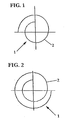
- Figure 1 is a transversal section view of a protective tube manufactured with the procedure of this present invention, that has a 25% proportion of its longitudinal ends overlapped;
- Figure 2 is a transversal section view similar to figure 1, with a 75% proportion of its longitudinal ends overlapped;
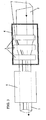
- Figure 3 is an outline drawing of the station where the shaping is carried out by heat using the present invention procedure;
- Figure 4 is an outline drawing of the station where the impregnation of the flat bands is carried out on a shaping material;
- Figure 5 is an outline drawing of the adhesion station for sheets where to said flat bands;
- Figure 6 is a plan view of a tube manufactured by means of the procedure of this present invention in the form of a Y; and
- Figure 7 is a transversal section view of the tube made in Figure 6.
- In the first place it must be stated that in the present description "protective tube" is understood as the structure where the transversal section is represented in Figures 1 and 2. This meaning, protective tube (shown by means of the numerical reference 1) described here that is formed from a flat band and it is deformed in a way so that the longitudinal ends of same are overlapped, defining a closed structure that can be opened longitudinally.
- In Figure 1, the overlapped proportion is 25% and in Figure 2 it is 75%.
- The weaving of some bands of fabric is carried out on a Raschel loom by warp with the following characteristics:
- Make: Liba
- Model: Racop-06
- N° of knitting heads: 1
- Knitting head width: 130"
- N° of combs: 6 (of which 3 form the mesh)
- Gauge: 14 needles per inch
- Speed: approximately 600 rows of mesh/min
- This type of fabric is standard and the workings and possibilities are known by any technician in the industry.
- Some 25 bands of fabric are obtained simultaneously (indicated by means of reference number 2) with widths of between 50 and 200mm with the following characteristics.
- Structure of three combs with the following movements:
- P-1: 2-0/0-2// linked to the stud chain
- P-2: 2-4/2-0// linked to the knitting
- P-3: 0-0/8-8// linked to the weft on four needles
- Threading and materials of the combs:
- P-1: full; polyester mono-filament (PET) with a 0.22 mm diameter or polyamide monofilament (PA) with a 0.20 mm diameter.
- P-2; full; polyester (PET) multifilament 500 dtex
- P-3; full; polyester (PET) monofilament 0.22 mm diameter
- Longitudinal density: 6 mesh rows per cm
- Transversal density: 7 mesh columns per cm
- With this structure, materials and weft, bands are obtained with the following properties:
- High resistance to abrasion: 300,000 cycles as a minimum before breaking on Trial ARP 15-36A compared to the resistance of approximately 60,000 cycles in the same trial on bands produced with other methods. This resistance is mainly given by the PET or PA threads disposed in the P-1.
- 2,400 hours resistance to temperature at 175°C without loss of mechanical properties.
- 1.5 mm thickness with a gram weight of 350 gr/m2 which gives good thermal and sound insulating properties. This significant thickness, compared with woven fabrics that are around 0.5 mm, with a relatively low gram weight are obtained thanks to the superimposing of the structures of each one of the three combs and the fact that in P-2 'tangle' type multifilament threads have been disposed.
- 10% maximum longitudinal shrinkage after 4 hours at 175°C. As a result of the fact that P-1 carries out a low retraction linking of the PET (polyester) or PA (polyamide) monofilament stud chain.
- The bands are likely to be subjected to a shaping stage, as the PET threads disposed in P-3 carrying out a linking of the mesh on four needles can give a tubular shape to the band in a subsequent process.
- Next the bands are subjected to a shaping stage (the station being represented in Figure 2) making them pass over some rings (3) lined up on the longitudinal axis of the band (2) and which have decreasing diameters as the band (2) advances on the inside. These rings (3) make the bands (2) fold in such a way that the two longitudinal ends converge one towards the other until first they meet and then overlap forming a tubular structure with a section that by preference is circular, although it could also have other sections such as square, triangular, oval, etc., in line with the internal section of the rings. With the diameter of the last ring (3) and the overlapped area of the two longitudinal ends of the band (2) that is approximately 50% of the total width of same, the internal diameter of the tubular (1) fabric structure is determined. This overlapped area is made by the difference between the width of the band (2) and the perimeter of the internal space of the last ring (3).
- This stage is carried out in an oven (4) at a temperature of some 350°C and a speed of band passage of some 6 metres per minute. Next the shaped tube (1) is passed through a low temperature (5) area in order to cause its rapid cooling. This achieves the polyester thread exceeding the softening temperature and then the polyester re-crystallises in such a way that it is fixed in the position in which it was when it was subjected to the rapid cooling.
- This shaping stage is particularly effective thanks to the P-1 and P-2 comb linking structure in which the polyester threads are disposed. This makes the resulting tube (1) have an optimum coiling strength, flexibility and elasticity for its use on the substrate to be protected likewise its maintenance over a long period of time.
- In the second preferred embodiment the following variables are introduced compared to the first:
- Structure of the four combs in accordance with the following movements:
- P-1: 2-0/0-2/4-6/6-4/ linked to the offset stud chain
- P-2: 4-6/6-4/2-0/0-2// linked to the offset stud chain
- P-3: 2-4/2-0// linked to the weft
- P-4: 0-0/8-8// linked to the weft on four needles
- Threading and materials of the combs:
- P-1: 1 full -1 empty; polyester mono-filament (PET) with a 0.22 mm diameter or polyamide monofilament (PA) with a 0.20 mm diameter.
- P-2; 1 full - 1 empty; polyester mono-filament (PET) with a 0.22 mm diameter or polyamide monofilament (PA) with a 0.20 mm diameter.
- P-3; full; polyester (PET) multifilament 500 dtex
- P-4: full: high retraction polyester (PET) monofilament 0.22 mm diameter
- The shaping phase that is subsequently carried out with the bands obtained in the weaving is the same as that described in the first preferred embodiment.
- With this structure, materials and linking and subsequent to the shaping stage a tubular structure is obtained that, in addition to having the tube properties described in the first embodiment, has the following improvements:
- Increased rolling strength due to the fact that the PET threads disposed are high retraction (approximately 40% at 160°C) in P-4. By passing the bands through a hot area in the shaping stage, these threads suffer a greater shrinkage than the rest of the threads that form the fabric's structure and on being disposed in a perpendicular position to the longitudinal axis of the band gives this bend greater strength with the two longitudinal edges coming together.
- Greater flexibility in the longitudinal direction due to the fact that on replacing the P-1 and P-2 stud chain linking structure, the threads of this comb, that are arranged in a fashion that is exclusively parallel to the longitudinal axis of the band, pass to a oblique position against this axis. By doing this the bending of the tube is achieved bringing the two transversal ends nearer to each other in such a way that the curvature radius (r) can be made smaller without producing the complete bending or collapsing of the tubular structure.
These two improvements to the tubular structure obtained in the first preferred embodiment make the product obtained in the second preferred embodiment process more suitable for use when, as a result of the curvature or irregularity nature of the substrate shape to be covered, greater rolling strength and ease of curving is required. - In the third preferred embodiment the following variables are introduced compared to the first:
- Structure of the two combs in accordance with the following movements:
- P-1: 2-0/0-2//linked to the offset stud chain
- P-2: 0-0/6-6//linked to the weft on three needles
- Threading and materials of the combs:
- P-1: full; fibre glass multifilament 68x2 tex.
- P-2; full; fibre glass multifilament 68x2 tex.
- With this linking structure, materials and weft, bands are obtained that, different to those obtained in the first and second preferred embodiments are characterised by their high resistance to temperature in such a way that said bands can support temperatures of 600°C for 90 hours have a loss of their mechanical properties not in excess of 50%.
- In the shaping stage of this embodiment, the impregnation of the bands is carried out with a silicone or resin compound, such as Acrylic PR Resin from the Repsol Company. This impregnation is carried out by the immersion of the bands in a bath (6) shown in figure 4 that contains the silicone or resin and the subsequent removal of the excess product on passing the bands (2) over some rollers that act as a grid. Then the bands (2) pass through the shaping stage as described in
Embodiment 1 with which the silicone or resin polymerises at the point when the bands acquire the tubular shape, thus this shape being fixed. - The structure obtained in the third preferred embodiment is especially preferable for the protection of conduits that are in high temperatures and at the same time act as thermal insulation being able to be used in areas where the protective tubes obtained by other processes or other materials are unusable after a few hours subjected to working temperatures.
- In the fourth preferred embodiment the following variables are introduced compared to the third:
- Structure of the two combs in accordance with the following movements:
- P-1: 2-0/0-2// linked to the stud chain
- P-2: 6-6/0-0//linked to the weft on three needles
- P-3: 0-0/6-6// linked to the weft on three needles
- Threading and materials of the combs:
- P-1: full; stainless steel multifilament 127x2 tex.
- P-2; full; fibre glass multifilament 68x2 tex.
- P-3; full; fibre glass multifilament 68x2 tex.
- With this linking structure, materials and weft, bands are obtained that, in addition to the thermal insulation and resistance properties, offer some values of resistance to friction that are extremely high given by the fact that in P-1, which carries out the linking of the stud chain, 316L stainless steel 127x2 tex multifilament threads are incorporated from the Sprint Metal company and in P-2 and P-3 the mesh links are made on three needles with opposite movements.
- The tubular structure obtained in this embodiment is especially suitable in the cases in which combined high thermal resistance and abrasion have to be obtained.
- In the fifth preferred embodiment the following variables are introduced compared to the first:
- Structure of the four combs in accordance with the following movements:
- P-1: 2-0/0-2// linked to the stud chain
- P-2: 2-0/2-4/4-6/4-2// atlas linking
- P-3: 4-6/4-2/2-0/2-4// atlas linking
- P-4: 0-0/8-8// linked to the weft on four needles
- Threading and materials of the combs:
- P-1: full ; polyester mono-filament (PET) with a 0.22 mm diameter or polyamide monofilament (PA) with a 0.20 mm diameter.
- P-2; full; polyester multifilament (PET 80%) and stainless steel (INOX 20%) 820 dtex.
- P-3; full; polyester multifilament (PET 80%) and stainless steel (INOX 20%) 820 dtex.
- P-4: full: polyester (PET) monofilament 0.22 mm diameter
- The shaping phase that is subsequently carried out with the bands obtained in the weaving is the same as that described in the first preferred embodiment.
- With this structure, materials and weft bands and subsequent to the shaping stage, tubular structures are obtained that, in addition to having the tube properties described in the first embodiment, have the following improvements:
- Screening effect for electromagnetic radiation as a result of the fact that P-2 and P-3 have polyester multifilament threads twisted with Politex Inox Resistex 80% PET +20% INOX 820 dtex stainless steel filaments made by the Tecnofilati Company and the fact that the two combs carry out an atlas type crossed link on three needles. The combination of the high electrical conductivity of these threads with the high covering factor of the fabric by the linking carried out makes a tubular structure that is especially suitable to protect and screen electrical cables likely to be affected by electromagnetic radiation (EMI).
- In the sixth preferred embodiment the following variables are introduced compared to the first:
- Longitudinal density: 4 mesh rows per cm
- Transversal density: 3.5 mesh rows per cm
- Structure of two combs with the following movements:
- P-1: 2-0/0-2// linked to the stud chain
- P-2: 0-0/8-8// linked to weft on four needles
- Threading and materials of the combs:
- P-1: full; polyester mono-filament (PET) with a 0.22 mm diameter or polyamide monofilament (PA) with a 0.20 mm diameter.
- P-2; full high retraction; polyester mono-filament (PET) with a 0.22 mm diameter.
- A sheet of an aluminium-polyester compound (7) is applied subsequent to the weaving of the bands which is adhered to them by means of welds (Figure 5), although other means can be used for this adhesion such as gluing.
- The shaping stage that is subsequently carried out, with the band compound of the fabric-aluminium sheet (8) obtained, is the same as that described in the first preferred embodiment.
- In this case the structure of the band, with the stud chain and weft links in P-1 and P-2 respectively, likewise the exclusive use of monofilament thread, is optimal to achieve a an aluminium sheet support fabric which has maximum mechanical resistance with minimum cost.
- The resulting tubular structure, after the shaping stage, with the aluminium sheet on the inside or the outside of the tube to achieve a high screening effect is particularly suitable to protect and screen electrical cables likely to be affected by electromagnetic radiation (EMI).
- In the seventh preferred embodiment the following variables are introduced above the first embodiment
- Structure of four combs with the following movements:
- P-1: 2-0/0-2// linked to the stud chain
- P-2: 2-4/2-0// linked to the knitting
- P-3: 20-0/8-8// linked to the weft on four needles
- P-4: 0-0/8-8/0-0/2-2// linked to the weft on four needles alternating with weaving link on two needles.
- Threading and materials of the combs:
- P-1: full; polyester mono-filament (PET) with a 0.22 mm diameter or polyamide monofilament (PA) with a 0.20 mm diameter.
- P-2; full; polyester (PET) multifilament 500 dtex
- P-3; full (except in the opening area and the band); polyester (PET) monofilament 0.22 mm diameter
- P-4: full (except in the opening area and the band); polyester (PET) monofilament 0.22 mm diameter.
- The shaping phase that is subsequently carried out with the bands obtained in the weaving is the same as that described in the first preferred embodiment.
- With this four comb linking structure a band (9) is obtained with a central longitudinal opening in the shape of a Y, shown in Figures 6 and 7, it being possible to programme the length of the unit part and the starting point in line with the loom drawing.
- In this way, after converting the flat band into a tubular structure in the shaping stage, a protective covering is obtained with properties described in the first preferred embodiment, but with the peculiarity that it is optimal for its fitting on conduits or cabling with a Y shape.
- In spite of making reference to a specific embodiment of the invention, it is clear to an expert in the industry that the procedure described is capable of numerous variations and modifications, and that all of the details stated can be replaced by others that are technically equivalent, without moving away from the sphere of the protection defined by the attached claims.
Claims (9)
- A procedure for the manufacture of protective tubes that has the following stages:- The obtaining of a plurality of flat knitted fabric bands by warping via a Raschel flat type of loom; and- Shaping said flat bands so that the longitudinal ends of each band join together and overlap defining a tubular shape.
- A procedure according to Claim 1, characterised in that said shaping is carried out making each one of the flat bands pass through some elements whose transversal section is gradually reduced.
- A procedure according to Claim 1 or 2, characterised in that said shaping is carried out at temperatures between 150°C and 400°C.
- A procedure according to Claim 2, characterised in that said flat bands advance in the shaping stage at a speed of between 5 and 15 metres/minute.
- A procedure according to Claim 1, characterised in that said overlap between the longitudinal ends of each one of the bands has a proportion of between 25% and 75% of the total band width.
- A procedure according to Claim 1, characterised in that said shaping stage includes the impregnation of the flat bands with a shaping product.
- A procedure according to Claim 6, characterised in that said shaping product is silicone or resin.
- A procedure according to Claim 1, characterised in that there is stage for the adhesion of a sheet to said flat bands prior to said shaping.
- A procedure according to Claim 8, characterised in that said sheet is made of aluminium and polyester.
Applications Claiming Priority (2)
| Application Number | Priority Date | Filing Date | Title |
|---|---|---|---|
| ES200401135A ES2243133B1 (en) | 2004-05-12 | 2004-05-12 | PROCEDURE FOR THE MANUFACTURE OF PROTECTION PIPES. |
| PCT/ES2005/000256 WO2005108845A1 (en) | 2004-05-12 | 2005-05-12 | Method of producing protective tubes |
Publications (1)
| Publication Number | Publication Date |
|---|---|
| EP1746324A1 true EP1746324A1 (en) | 2007-01-24 |
Family
ID=35320298
Family Applications (1)
| Application Number | Title | Priority Date | Filing Date |
|---|---|---|---|
| EP05748801A Withdrawn EP1746324A1 (en) | 2004-05-12 | 2005-05-12 | Method of producing protective tubes |
Country Status (6)
| Country | Link |
|---|---|
| US (1) | US8557073B2 (en) |
| EP (1) | EP1746324A1 (en) |
| CN (1) | CN100520141C (en) |
| ES (1) | ES2243133B1 (en) |
| MX (1) | MXPA06007644A (en) |
| WO (1) | WO2005108845A1 (en) |
Cited By (6)
| Publication number | Priority date | Publication date | Assignee | Title |
|---|---|---|---|---|
| EP2331745A2 (en) * | 2008-09-05 | 2011-06-15 | Federal-Mogul Powertrain, Inc. | Self-wrapping textile sleeve with protective coating and method of construction thereof |
| WO2014140207A1 (en) * | 2013-03-15 | 2014-09-18 | Delfingen Fr-Anteuil | Elongate self-closing sleeve for protecting elongate members |
| WO2014159807A1 (en) * | 2013-03-13 | 2014-10-02 | Federal-Mogul Powertrain, Inc. | Warp knit wrappable sleeve with extendable electro-functional yarns and method of construction thereof |
| DE102014119751A1 (en) | 2014-12-31 | 2016-06-30 | Michael Lindner | Method for producing a protective device |
| EP2486572A4 (en) * | 2009-10-07 | 2017-04-26 | Federal-Mogul Powertrain, Inc. | Flexible textile sleeve with end fray resistant, protective coating and method of construction thereof |
| EP4008820A1 (en) * | 2020-12-01 | 2022-06-08 | Relats, S.A. | A protective sleeve for electrically and thermally protecting an electrically conductive busbar and a method for obtaining the protective sleeve |
Families Citing this family (6)
| Publication number | Priority date | Publication date | Assignee | Title |
|---|---|---|---|---|
| US7395680B2 (en) * | 2004-07-20 | 2008-07-08 | Federal Mogul Worldwide, Inc. | Self-curling knitted sleeve and method of fabrication |
| WO2009010599A1 (en) * | 2007-07-17 | 2009-01-22 | Relats, S.A. | Flexible protective cover and method for manufacture thereof |
| ES2439818B1 (en) * | 2012-07-23 | 2014-12-29 | Relats, S.A. | TUBULAR PROTECTION COVER |
| KR101359465B1 (en) | 2013-11-11 | 2014-02-07 | 한미케이블 주식회사 | Manufacturing device for curled fabric |
| DE102014209826A1 (en) * | 2014-05-23 | 2015-11-26 | Contitech Ag | Insulating element or insulating system for sheathing a body |
| US10711378B2 (en) * | 2016-07-13 | 2020-07-14 | Federal-Mogul Powertrain Llc | Knit textile sleeve with self-sustaining expanded and contracted states and method of construction thereof |
Citations (2)
| Publication number | Priority date | Publication date | Assignee | Title |
|---|---|---|---|---|
| US4570789A (en) * | 1983-04-22 | 1986-02-18 | Polygress Plastic Gmbh | Bale of straw or hay |
| EP0425099A2 (en) * | 1989-09-28 | 1991-05-02 | Milliken Europe N.V. | Stabilised fabrics |
Family Cites Families (11)
| Publication number | Priority date | Publication date | Assignee | Title |
|---|---|---|---|---|
| US4477693A (en) * | 1982-12-09 | 1984-10-16 | Cooper Industries, Inc. | Multiply shielded coaxial cable with very low transfer impedance |
| US4631098A (en) * | 1983-01-06 | 1986-12-23 | Raychem Limited | Heat-recoverable article |
| BG41756A1 (en) * | 1985-01-22 | 1987-08-14 | Ribarev | Round knittings with warp- knitted structure and method for their manufacture |
| ES2007818A6 (en) * | 1988-04-08 | 1989-07-01 | Tejidos Telats S A | Insulation sleeving |
| US4929478A (en) * | 1988-06-17 | 1990-05-29 | The Bentley-Harris Manufacturing Company | Protective fabric sleeves |
| US5413149A (en) * | 1991-11-05 | 1995-05-09 | The Bentley-Harris Manufacturing Company | Shaped fabric products and methods of making same |
| DE19804221A1 (en) * | 1998-02-04 | 1999-08-05 | Natec Reich Summer Gmbh Co Kg | Method and device for producing a continuous film tube from a flat film web |
| ES2156049B1 (en) * | 1998-04-01 | 2002-02-01 | Relats Sa | PROCEDURE FOR THE TREATMENT OF PROTECTION PIPES. |
| US6649828B2 (en) * | 2000-05-02 | 2003-11-18 | Custom Coated Components, Inc | Self-sealing reflective sleeve |
| ES2190725B1 (en) * | 2001-03-02 | 2004-05-01 | Relats, S.A. | USE OF A POINT GENDER MACHINE PER URDIDE FOR THE MANUFACTURE OF AN OPEN OR CLOSED PROTECTION TUBE OF CABLES, CONDUCT AND SIMILAR, AND PROTECTION TUBE MANUFACTURED WITH THE MACHINE. |
| US20050124249A1 (en) * | 2003-12-09 | 2005-06-09 | Uribarri Peter V. | Abrasion-resistant sleeve for wiring and the like |
-
2004
- 2004-05-12 ES ES200401135A patent/ES2243133B1/en active Active
-
2005
- 2005-05-12 CN CNB2005800151570A patent/CN100520141C/en active Active
- 2005-05-12 WO PCT/ES2005/000256 patent/WO2005108845A1/en not_active Application Discontinuation
- 2005-05-12 MX MXPA06007644A patent/MXPA06007644A/en active IP Right Grant
- 2005-05-12 EP EP05748801A patent/EP1746324A1/en not_active Withdrawn
- 2005-05-12 US US10/589,485 patent/US8557073B2/en not_active Expired - Fee Related
Patent Citations (3)
| Publication number | Priority date | Publication date | Assignee | Title |
|---|---|---|---|---|
| US4570789A (en) * | 1983-04-22 | 1986-02-18 | Polygress Plastic Gmbh | Bale of straw or hay |
| EP0425099A2 (en) * | 1989-09-28 | 1991-05-02 | Milliken Europe N.V. | Stabilised fabrics |
| US5229056A (en) * | 1989-09-28 | 1993-07-20 | Willy De Meyer | Producing fabric reinforced hose |
Non-Patent Citations (1)
| Title |
|---|
| See also references of WO2005108845A1 * |
Cited By (12)
| Publication number | Priority date | Publication date | Assignee | Title |
|---|---|---|---|---|
| EP2331745A2 (en) * | 2008-09-05 | 2011-06-15 | Federal-Mogul Powertrain, Inc. | Self-wrapping textile sleeve with protective coating and method of construction thereof |
| EP2331745A4 (en) * | 2008-09-05 | 2014-04-16 | Federal Mogul Powertrain Inc | Self-wrapping textile sleeve with protective coating and method of construction thereof |
| US9336924B2 (en) | 2008-09-05 | 2016-05-10 | Federal-Mogul Powertrain, Inc. | Self-wrapping textile sleeve with protective coating and method of construction thereof |
| EP2486572A4 (en) * | 2009-10-07 | 2017-04-26 | Federal-Mogul Powertrain, Inc. | Flexible textile sleeve with end fray resistant, protective coating and method of construction thereof |
| WO2014159807A1 (en) * | 2013-03-13 | 2014-10-02 | Federal-Mogul Powertrain, Inc. | Warp knit wrappable sleeve with extendable electro-functional yarns and method of construction thereof |
| JP2016519221A (en) * | 2013-03-13 | 2016-06-30 | フェデラル−モーグル パワートレイン インコーポレイテッドFederal−Mogul Powertrain, Inc. | Wrapping sleeve with warp knitting with extendable electrical function yarn and method of construction |
| US9745679B2 (en) | 2013-03-13 | 2017-08-29 | Federal-Mogul Powertrain | Warp knit wrappable sleeve with extendable electro-functional yarns and method of construction thereof |
| WO2014140207A1 (en) * | 2013-03-15 | 2014-09-18 | Delfingen Fr-Anteuil | Elongate self-closing sleeve for protecting elongate members |
| US9657417B2 (en) | 2013-03-15 | 2017-05-23 | Delfingen Fr-Anteuil | Elongate self-closing sleeve for protecting elongate members having improved sound dampening quality |
| DE102014119751A1 (en) | 2014-12-31 | 2016-06-30 | Michael Lindner | Method for producing a protective device |
| DE102014119751B4 (en) | 2014-12-31 | 2017-03-02 | Michael Lindner | Method for producing a protective device |
| EP4008820A1 (en) * | 2020-12-01 | 2022-06-08 | Relats, S.A. | A protective sleeve for electrically and thermally protecting an electrically conductive busbar and a method for obtaining the protective sleeve |
Also Published As
| Publication number | Publication date |
|---|---|
| CN100520141C (en) | 2009-07-29 |
| WO2005108845A1 (en) | 2005-11-17 |
| US20070169876A1 (en) | 2007-07-26 |
| WO2005108845A8 (en) | 2005-12-15 |
| ES2243133A1 (en) | 2005-11-16 |
| US8557073B2 (en) | 2013-10-15 |
| ES2243133B1 (en) | 2006-07-01 |
| CN1961172A (en) | 2007-05-09 |
| MXPA06007644A (en) | 2006-09-01 |
Similar Documents
| Publication | Publication Date | Title |
|---|---|---|
| US8557073B2 (en) | Method of producing protective tubes | |
| US11053615B2 (en) | Metal alloy knit fabric for high temperature insulating materials | |
| EP2971307B1 (en) | Warp knit wrappable sleeve with extendable electro-functional yarns and method of construction thereof | |
| EP3346033B1 (en) | Single-layer ceramic-based knit fabric for high temperature bulb seals | |
| CN101390264B (en) | Self-curling knitted sleeve and method of fabrication | |
| CN100533890C (en) | Flexible protective corrugated tube | |
| RU2704458C2 (en) | Thermal protection made by knitting from multiple materials as a whole, for use in industry and for vehicles | |
| EP2743386A1 (en) | Conductive fabric and method and apparatus for manufacturing same | |
| CN107109730B (en) | Braided textile sleeve with self-retaining extended and retracted states and method of construction thereof | |
| MXPA05000198A (en) | Multiple layer insulating sleeve. | |
| KR20090086264A (en) | Protective sleeve assembly having support member and method of construction | |
| KR102567646B1 (en) | Self-wrapping braided fabric sleeve having expanded and contracted states while supporting itself and manufacturing method thereof | |
| US6854298B2 (en) | Methods and systems for providing a protecting tube | |
| MX2011005126A (en) | Protective tube and related manufacturing method. | |
| JP7019666B2 (en) | Knitted textile sleeves with self-sustaining expansion and contraction states and how to build them | |
| CN218352052U (en) | Telescopic wear-resistant sheath and plastic-coated pipe |
Legal Events
| Date | Code | Title | Description |
|---|---|---|---|
| PUAI | Public reference made under article 153(3) epc to a published international application that has entered the european phase |
Free format text: ORIGINAL CODE: 0009012 |
|
| 17P | Request for examination filed |
Effective date: 20060629 |
|
| AK | Designated contracting states |
Kind code of ref document: A1 Designated state(s): AT BE BG CH CY CZ DE DK EE ES FI FR GB GR HU IE IS IT LI LT LU MC NL PL PT RO SE SI SK TR |
|
| DAX | Request for extension of the european patent (deleted) | ||
| 17Q | First examination report despatched |
Effective date: 20071213 |
|
| GRAP | Despatch of communication of intention to grant a patent |
Free format text: ORIGINAL CODE: EPIDOSNIGR1 |
|
| STAA | Information on the status of an ep patent application or granted ep patent |
Free format text: STATUS: THE APPLICATION IS DEEMED TO BE WITHDRAWN |
|
| 18D | Application deemed to be withdrawn |
Effective date: 20090428 |