EP1746281A2 - Arrangement having a magnet circuit with a radial orientable connector - Google Patents
Arrangement having a magnet circuit with a radial orientable connector Download PDFInfo
- Publication number
- EP1746281A2 EP1746281A2 EP06114402A EP06114402A EP1746281A2 EP 1746281 A2 EP1746281 A2 EP 1746281A2 EP 06114402 A EP06114402 A EP 06114402A EP 06114402 A EP06114402 A EP 06114402A EP 1746281 A2 EP1746281 A2 EP 1746281A2
- Authority
- EP
- European Patent Office
- Prior art keywords
- arrangement
- magnetic circuit
- electrical connection
- housing component
- plug contact
- Prior art date
- Legal status (The legal status is an assumption and is not a legal conclusion. Google has not performed a legal analysis and makes no representation as to the accuracy of the status listed.)
- Granted
Links
Images
Classifications
-
- F—MECHANICAL ENGINEERING; LIGHTING; HEATING; WEAPONS; BLASTING
- F02—COMBUSTION ENGINES; HOT-GAS OR COMBUSTION-PRODUCT ENGINE PLANTS
- F02M—SUPPLYING COMBUSTION ENGINES IN GENERAL WITH COMBUSTIBLE MIXTURES OR CONSTITUENTS THEREOF
- F02M63/00—Other fuel-injection apparatus having pertinent characteristics not provided for in groups F02M39/00 - F02M57/00 or F02M67/00; Details, component parts, or accessories of fuel-injection apparatus, not provided for in, or of interest apart from, the apparatus of groups F02M39/00 - F02M61/00 or F02M67/00; Combination of fuel pump with other devices, e.g. lubricating oil pump
- F02M63/02—Fuel-injection apparatus having several injectors fed by a common pumping element, or having several pumping elements feeding a common injector; Fuel-injection apparatus having provisions for cutting-out pumps, pumping elements, or injectors; Fuel-injection apparatus having provisions for variably interconnecting pumping elements and injectors alternatively
- F02M63/0225—Fuel-injection apparatus having a common rail feeding several injectors ; Means for varying pressure in common rails; Pumps feeding common rails
-
- F—MECHANICAL ENGINEERING; LIGHTING; HEATING; WEAPONS; BLASTING
- F02—COMBUSTION ENGINES; HOT-GAS OR COMBUSTION-PRODUCT ENGINE PLANTS
- F02M—SUPPLYING COMBUSTION ENGINES IN GENERAL WITH COMBUSTIBLE MIXTURES OR CONSTITUENTS THEREOF
- F02M51/00—Fuel-injection apparatus characterised by being operated electrically
- F02M51/005—Arrangement of electrical wires and connections, e.g. wire harness, sockets, plugs; Arrangement of electronic control circuits in or on fuel injection apparatus
-
- F—MECHANICAL ENGINEERING; LIGHTING; HEATING; WEAPONS; BLASTING
- F02—COMBUSTION ENGINES; HOT-GAS OR COMBUSTION-PRODUCT ENGINE PLANTS
- F02M—SUPPLYING COMBUSTION ENGINES IN GENERAL WITH COMBUSTIBLE MIXTURES OR CONSTITUENTS THEREOF
- F02M59/00—Pumps specially adapted for fuel-injection and not provided for in groups F02M39/00 -F02M57/00, e.g. rotary cylinder-block type of pumps
- F02M59/20—Varying fuel delivery in quantity or timing
- F02M59/36—Varying fuel delivery in quantity or timing by variably-timed valves controlling fuel passages to pumping elements or overflow passages
- F02M59/366—Valves being actuated electrically
-
- F—MECHANICAL ENGINEERING; LIGHTING; HEATING; WEAPONS; BLASTING
- F02—COMBUSTION ENGINES; HOT-GAS OR COMBUSTION-PRODUCT ENGINE PLANTS
- F02M—SUPPLYING COMBUSTION ENGINES IN GENERAL WITH COMBUSTIBLE MIXTURES OR CONSTITUENTS THEREOF
- F02M63/00—Other fuel-injection apparatus having pertinent characteristics not provided for in groups F02M39/00 - F02M57/00 or F02M67/00; Details, component parts, or accessories of fuel-injection apparatus, not provided for in, or of interest apart from, the apparatus of groups F02M39/00 - F02M61/00 or F02M67/00; Combination of fuel pump with other devices, e.g. lubricating oil pump
- F02M63/0012—Valves
- F02M63/0014—Valves characterised by the valve actuating means
- F02M63/0015—Valves characterised by the valve actuating means electrical, e.g. using solenoid
-
- F—MECHANICAL ENGINEERING; LIGHTING; HEATING; WEAPONS; BLASTING
- F16—ENGINEERING ELEMENTS AND UNITS; GENERAL MEASURES FOR PRODUCING AND MAINTAINING EFFECTIVE FUNCTIONING OF MACHINES OR INSTALLATIONS; THERMAL INSULATION IN GENERAL
- F16K—VALVES; TAPS; COCKS; ACTUATING-FLOATS; DEVICES FOR VENTING OR AERATING
- F16K27/00—Construction of housing; Use of materials therefor
- F16K27/02—Construction of housing; Use of materials therefor of lift valves
- F16K27/029—Electromagnetically actuated valves
-
- F—MECHANICAL ENGINEERING; LIGHTING; HEATING; WEAPONS; BLASTING
- F16—ENGINEERING ELEMENTS AND UNITS; GENERAL MEASURES FOR PRODUCING AND MAINTAINING EFFECTIVE FUNCTIONING OF MACHINES OR INSTALLATIONS; THERMAL INSULATION IN GENERAL
- F16K—VALVES; TAPS; COCKS; ACTUATING-FLOATS; DEVICES FOR VENTING OR AERATING
- F16K31/00—Actuating devices; Operating means; Releasing devices
- F16K31/02—Actuating devices; Operating means; Releasing devices electric; magnetic
- F16K31/06—Actuating devices; Operating means; Releasing devices electric; magnetic using a magnet, e.g. diaphragm valves, cutting off by means of a liquid
-
- F—MECHANICAL ENGINEERING; LIGHTING; HEATING; WEAPONS; BLASTING
- F02—COMBUSTION ENGINES; HOT-GAS OR COMBUSTION-PRODUCT ENGINE PLANTS
- F02M—SUPPLYING COMBUSTION ENGINES IN GENERAL WITH COMBUSTIBLE MIXTURES OR CONSTITUENTS THEREOF
- F02M2200/00—Details of fuel-injection apparatus, not otherwise provided for
- F02M2200/80—Fuel injection apparatus manufacture, repair or assembly
Definitions
- the invention relates to an arrangement with a magnetic circuit with a radially orientable plug contact, for example, this is an arrangement in an electromagnetic pressure control valve, which is adjusted over a duty cycle of the power supply.
- pressure control valves are used for pressure control in storage injection systems. These injection systems include a high-pressure accumulator, which is supplied via a high-pressure pump with high-pressure fuel.
- a pressure control is involved, i. a pressure sensor axially arranged on the high-pressure storage space and an electromagnetic pressure control valve, whereby the pressure in the high-pressure accumulator chamber is adjusted quickly and precisely, so that a constant system pressure at different flow rates is possible.
- a plug contact for an electrical connection can not be made axially, but the plug contact is oriented in the radial direction, wherein an end position afflicted with a certain angular tolerance is set.
- An exact angular orientation of a plug contact is often not possible.
- only a very limited space available for such arrangements with a magnetic circuit is only a very limited space available for such arrangements with a magnetic circuit.
- this results in the need for a compact arrangement which on the other hand results in high demands on the manufacturing tolerances and complex geometries of the components involved, which adversely affect the costs.
- connection of an electrical connection with a housing component, in which a magnetic coil is integrated by means of a flange, a union nut, a threaded connection, being provided on both components at an angle oriented threads, or via sliding contacts between the solenoid and electrical connection.
- This is intended to achieve a specific angular orientation of a plug contact included in the electrical connection in the mounted state of the arrangement at its destination.
- an adjustable pressure control valve with an electrical connection for fuel injection systems is known, which is associated with a high-pressure delivery unit, which is arranged between a high-pressure side and a low-pressure side and comprises a valve element which can be controlled via an electric actuator.
- the electric actuator is designed as an electromagnetic actuator.
- the pressure regulating valve has an electrical connection which is connected to a housing component via a screw connection. In the housing component, an anchor plate is received, which acts on the one hand by a compression spring and on the other hand, a likewise disposed in the housing component electromagnet opposite.
- the housing component of the pressure regulating valve has a deformable region, by means of which a gap can be set between the surfaces of the electrically controllable actuator arrangement of the magnet system anchor plate / magnetic core when the pressure regulating valve is mounted on a receiving body.
- a gap can be set between the surfaces of the electrically controllable actuator arrangement of the magnet system anchor plate / magnetic core when the pressure regulating valve is mounted on a receiving body.
- the object of the present invention is to provide an arrangement with a magnetic circuit on which an electrical connection in the form of a plug contact with a radially orientable orientation is provided.
- Radial angular orientation of the integrated plug contact of the arrangement proposed according to the invention with a magnetic circuit comprising a preassembled unit and a housing component accommodating this unit is possible after installation of the entire arrangement with a magnetic circuit in a receiving body in a narrow angular tolerance range.
- the arrangement with a magnetic circuit comes without additional components, in particular union nut or flange, from and therefore offers a cost effective and easy to implement solution. Close manufacturing tolerances and complex geometries of the individual components are not necessary to achieve a radial alignment of the plug contact according to the requirements after installation of the arrangement with a magnetic circuit.
- the arrangement with a magnetic circuit comprises a preassembled unit, which combines a magnetic coil, at least one intermediate disc and a cover plate with an integrated electrical connection. These components are rotatably connected to each other in an arbitrary or with respect to a reference surface orientable position. The rotationally fixed connection of the individual components can be done by friction and / or positive engagement.
- This preassembled unit is accommodated in a housing component, whereby the proposed arrangement is provided with a magnetic circuit whose electrical connection has a radially orientable plug contact.
- the arrangement with a magnetic circuit can be accommodated, for example, by an axial screw in a receiving body.
- the final radial alignment of the plug contact of the electrical connection can be made in the desired Winkelendposition.
- the entire preassembled unit consisting of magnetic coil, washer and end cap with integrated electrical connection, brought by applying a certain minimum torque in the desired Winkelendposition.
- the angle end position is with great accuracy, i. Affected with a narrow angle tolerance range, adjustable.
- the set Winkelendposition can be secured by friction. Alternatively, by a subsequent manufacturing step, e.g. by notching, the Winkelendposition be secured form-fitting.
- any radial angular orientation of a male contact of an electrical connection, integrated into a magnetic component having arrangement can be achieved.
- a magnetic circuit for example, part of a pressure control valve
- the electrical connection included can be aligned in a biased with a narrow angular tolerance radial orientation, wherein as the reference surface Component itself, with which the assembly is connected to a magnetic circuit, ie, the high-pressure pump or the high-pressure storage chamber, acts and the alignment is no longer bound to reference surfaces, such as a surface of a hexagon.
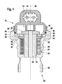
- the arrangement with a magnetic circuit 10 has a housing component 12 and a cover 14.
- the end cover 14 has an electrical connection 16, wherein a plug contact is integrated, via which an electrically controllable actuator integrated in the arrangement with a magnetic circuit 10 can be activated or deactivated.
- the electrical actuator is formed in the embodiment as an electromagnetic actuator whose details are not shown.
- a bore 18 is provided, into which a sleeve 20 is received.
- the housing 12 and the sleeve 20 may be made in one piece.
- the sleeve 20 serves for example to receive an anchor part, not shown.
- the sleeve 20 is partially enclosed by a preassembled magnetic coil 22, which has a winding unit 24 and an overmolding in the form of a sleeve 26 made of plastic such as plastic.
- PPS includes.
- the magnet coil 22 comprises a collar-shaped shoulder 28 which, for assembly reasons, has a conically tapering peripheral region 30.
- an annular surface 32 of the collar-shaped shoulder 28 of the magnetic coil 22 is located on an intermediate disc 34, wherein at the contact surface between the annular surface 32 and the intermediate disc 34 is a positive and / or frictional engagement, which can be made in the encapsulation.
- the intermediate disc 34 is in a form and / or frictional engagement with the end cover 14.
- a positive connection the connection between an outer periphery 36 of the washer 34 and a receiving portion 58 of the end cover 14 via a wedge or multi-wedge connection, a polygonal profile or a claw-shaped connection done.
- an end face 38 of the intermediate disk 34 it is likewise possible for an end face 38 of the intermediate disk 34 to be in positive engagement with a correspondingly formed region 60 of the end cover 14.
- a correspondingly shaped periphery 36 of the washer 34 ie, for example, serrated or polygonal profile, provides a cost-effective connection.
- the preassembled unit comprising solenoid 22, washer 34 and end cap 14 offers the advantage that the elements relevant to an electromagnetic actuator, i. Magnetic core, in which the solenoids of an electromagnet are accommodated, and an anchor plate 54, which is received for example in the end cover 14, can be brought into a predetermined position to each other, which does not change by a radial orientation of the electrical connection 16.
- an electromagnetic actuator i. Magnetic core, in which the solenoids of an electromagnet are accommodated, and an anchor plate 54, which is received for example in the end cover 14
- an anchor plate 54 which is received for example in the end cover 14
- the preassembled unit, including solenoid 22, washer 34 and end cap 14, is received in the housing component 12.
- the circumference 40 of the end cover 14 is formed such that the end cover 14, for example by means of a flange 42 or alternatively by means of a union nut with the housing component 12 is connectable.
- the end cover 14, including the intermediate disk 34 and the magnet coil 22 connected therewith in a rotationally fixed manner is pressed against a surface 44 of the housing component 12.
- a shoulder 46 is formed on the circumference 40 of the end cover 14, against which a sealing ring 48 abuts, which seals the end cover 14 against the housing component 12.
- the housing component 12 comprises at an end 50 opposite the end cap an external thread 52, which can be screwed into a corresponding thread on a - not shown - receiving body.
- the final radial orientation of the plug contact 16 takes place with a defined minimum torque in any Winkelendposition.
- the preassembled unit can be rotated 360 ° about its longitudinal axis 56.
Landscapes
- Engineering & Computer Science (AREA)
- General Engineering & Computer Science (AREA)
- Mechanical Engineering (AREA)
- Chemical & Material Sciences (AREA)
- Combustion & Propulsion (AREA)
- Physics & Mathematics (AREA)
- Electromagnetism (AREA)
- Magnetically Actuated Valves (AREA)
- Electrically Driven Valve-Operating Means (AREA)
- Electromagnets (AREA)
Abstract
Description
Die Erfindung betrifft eine Anordnung mit einem Magnetkreis mit einem radial orientierbaren Steckerkontakt, beispielsweise ist dies eine Anordnung in einem elektromagnetischen Druckregelventil, welches über ein Tastverhältnis der Stromversorgung verstellt wird. Derartige Druckregelventile werden zur Druckregelung in Speichereinspritzsystemen eingesetzt. Diese Einspritzsysteme umfassen einen Hochdruckspeicherraum, der über eine Hochdruckpumpe mit unter hohem Druck stehenden Kraftstoff versorgt wird. Hierbei ist eine Druckregelung umfasst, d.h. ein an dem Hochdruckspeicherraum jeweils axial angeordneter Drucksensor und ein elektromagnetisches Druckregelventil, wodurch der Druck in dem Hochdruckspeicherraum schnell und präzise eingestellt wird, so dass ein konstanter Systemdruck bei unterschiedlichen Volumenströmen möglich ist.The invention relates to an arrangement with a magnetic circuit with a radially orientable plug contact, for example, this is an arrangement in an electromagnetic pressure control valve, which is adjusted over a duty cycle of the power supply. Such pressure control valves are used for pressure control in storage injection systems. These injection systems include a high-pressure accumulator, which is supplied via a high-pressure pump with high-pressure fuel. Here, a pressure control is involved, i. a pressure sensor axially arranged on the high-pressure storage space and an electromagnetic pressure control valve, whereby the pressure in the high-pressure accumulator chamber is adjusted quickly and precisely, so that a constant system pressure at different flow rates is possible.
Häufig kann bei derartigen Anordnungen mit einem Magnetkreis aus Platzgründen ein Steckerkontakt für einen elektrischen Anschluss nicht axial ausgeführt werden, sondern der Steckerkontakt ist in radialer Richtung orientiert, wobei eine Endposition behaftet mit einer bestimmten Winkeltoleranz eingestellt wird. Eine exakte Winkelorientierung eines Steckerkontaktes ist häufig nicht möglich. Insbesondere stehen für derartige Anordnungen mit einem Magnetkreis nur ein äußerst begrenzter Bauraum zur Verfügung. Daraus ergibt sich einerseits die Notwendigkeit einer kompakten Anordnung, woraus sich andererseits hohe Anforderungen an die Fertigungstoleranzen sowie aufwendige Geometrien der umfassten Bauteile ergeben, die die Kosten ungünstig beeinflussen.Often, in such arrangements with a magnetic circuit for reasons of space, a plug contact for an electrical connection can not be made axially, but the plug contact is oriented in the radial direction, wherein an end position afflicted with a certain angular tolerance is set. An exact angular orientation of a plug contact is often not possible. In particular, only a very limited space available for such arrangements with a magnetic circuit. On the one hand, this results in the need for a compact arrangement, which on the other hand results in high demands on the manufacturing tolerances and complex geometries of the components involved, which adversely affect the costs.
Herkömmlicherweise erfolgt die Verbindung eines elektrischen Anschlusses mit einer Gehäusekomponente, in der eine Magnetspule integriert ist, mittels einer Flanschverbindung, einer Überwurfmutter, einer Gewindeverbindung, wobei an beiden Bauteilen im Winkel orientierte Gewinde vorgesehen sind, oder über Schleifkontakte zwischen Magnetspule und elektrischem Anschluss. Dadurch soll eine bestimmte Winkelausrichtung eines in dem elektrischen Anschluss umfassten Steckerkontaktes im montierten Zustand der Anordnung an seinem Bestimmungsort erreicht werden.Conventionally, the connection of an electrical connection with a housing component, in which a magnetic coil is integrated, by means of a flange, a union nut, a threaded connection, being provided on both components at an angle oriented threads, or via sliding contacts between the solenoid and electrical connection. This is intended to achieve a specific angular orientation of a plug contact included in the electrical connection in the mounted state of the arrangement at its destination.
Daraus erwachsen die Nachteile, dass zusätzliche Bauteile erforderlich sind, beispielsweise eine Überwurfmutter. Darüberhinaus muß ein entsprechend grösserer Bauraum bereitgestellt werden, wenn beispielsweise die Verbindung eines elektrischen Anschlusses mit einer Gehäusekomponente durch eine Flanschverbindung realisiert wird. Ebenso müssen enge Fertigungstoleranzen der einzelnen Bauteile eingehalten werden, um eine entsprechende Winkelorientierung des elektrischen Anschlusses zu erzielen. Dies führt zu einer kostenintensiven Anordnung, bei der die einzelnen Komponenten insgesamt oder auch nur in einzelnen Bereichen mit engen Fertigungstoleranzen behaftetet sind und/oder entsprechend eine aufwendige Bauteilgeometrie aufweisen.This causes the disadvantages that additional components are required, such as a union nut. In addition, a correspondingly larger space must be provided when, for example, the connection of an electrical connection with a housing component is realized by a flange connection. Likewise, close manufacturing tolerances of the individual components must be adhered to in order to achieve a corresponding angular orientation of the electrical connection. This leads to a cost-intensive arrangement in which the individual components are affected in total or even in individual areas with tight manufacturing tolerances and / or correspondingly have a complex component geometry.
Aus
Aufgabe der vorliegenden Erfindung ist es, eine Anordnung mit einem Magnetkreis bereitzustellen, an der ein elektrischer Anschluss in Form eines Steckerkontaktes mit einer radial orientierbaren Ausrichtung vorgesehen ist. Eine radiale Winkelausrichtung des integrierten Steckerkontaktes der erfindungsgemäß vorgeschlagenen Anordnung mit einem Magnetkreis, die eine vormontierte Einheit und eine diese Einheit aufnehmende Gehäusekomponente umfasst, ist nach dem Einbau der gesamten Anordnung mit einem Magnetkreis in einen Aufnahmekörper in einem engen Winkeltoleranzbereich möglich. Die Anordnung mit einem Magnetkreis kommt ohne zusätzliche Bauteile, insbesondere Überwurfmutter oder Flanschverbindung, aus und bietet demnach eine kostengünstige und einfach umzusetzende Lösung. Enge Fertigungstoleranzen und aufwendige Geometrien der einzelnen Bauteile sind nicht notwendig, um eine den Anforderungen entsprechende radiale Ausrichtung des Steckerkontaktes nach dem Einbau der Anordnung mit einem Magnetkreis zu erzielen.The object of the present invention is to provide an arrangement with a magnetic circuit on which an electrical connection in the form of a plug contact with a radially orientable orientation is provided. Radial angular orientation of the integrated plug contact of the arrangement proposed according to the invention with a magnetic circuit comprising a preassembled unit and a housing component accommodating this unit is possible after installation of the entire arrangement with a magnetic circuit in a receiving body in a narrow angular tolerance range. The arrangement with a magnetic circuit comes without additional components, in particular union nut or flange, from and therefore offers a cost effective and easy to implement solution. Close manufacturing tolerances and complex geometries of the individual components are not necessary to achieve a radial alignment of the plug contact according to the requirements after installation of the arrangement with a magnetic circuit.
Es wird eine Anordnung mit einem Magnetkreis vorgeschlagen, an dem ein elektrischer Anschluss in Form eines Steckerkontaktes mit einer radial orientierbaren Ausrichtung vorgesehen ist. Die Anordnung mit einem Magnetkreis umfasst eine vormontierte Einheit, welche eine Magnetspule, mindestens eine Zwischenscheibe und einen Abschlussdeckel mit einem integrierten elektrischen Anschluss zusammenfasst. Diese Komponenten sind in einer zueinander beliebigen oder bezogen auf eine Bezugsfläche orientierbaren Position drehfest miteinander verbunden. Die drehfeste Verbindung der einzelnen Komponenten kann durch Reib- und/oder Formschluß erfolgen. Diese vormontierte Einheit ist in einer Gehäusekomponente aufgenommen, wodurch die vorgeschlagene Anordnung mit einem Magnetkreis bereitgestellt wird, dessen elektrischer Anschluss einen radial orientierbaren Steckerkontakt aufweist. Die Anordnung mit einem Magnetkreis kann beispielsweise durch eine axiale Verschraubung in einen Aufnahmekörper aufgenommen werden. Nachdem die Anordnung mit einem Magnetkreis in dem Aufnahmekörper aufgenommen ist, kann die endgültige radiale Ausrichtung des Steckerkontaktes des elektrischen Anschlusses in die gewünschte Winkelendposition erfolgen. Dabei wird die gesamte vormontierte Einheit, bestehend aus Magnetspule, Zwischenscheibe und Abschlussdeckel mit integriertem elektrischen Anschluss, durch Aufbringen eines bestimmten Mindestdrehmomentes in die gewünschte Winkelendposition gebracht. Die Winkelendposition ist mit großer Exaktheit, d.h. behaftet mit einem engen Winkeltoleranzbereich, einstellbar. Die eingestellte Winkelendposition kann durch Reibschluß gesichert werden. Alternativ kann auch durch einen nachträglichen Fertigungsschritt, z.B. durch Verkerbung, die Winkelendposition formschlüssig gesichert werden.It is proposed an arrangement with a magnetic circuit to which an electrical connection in the form of a plug contact is provided with a radially oriented orientation. The arrangement with a magnetic circuit comprises a preassembled unit, which combines a magnetic coil, at least one intermediate disc and a cover plate with an integrated electrical connection. These components are rotatably connected to each other in an arbitrary or with respect to a reference surface orientable position. The rotationally fixed connection of the individual components can be done by friction and / or positive engagement. This preassembled unit is accommodated in a housing component, whereby the proposed arrangement is provided with a magnetic circuit whose electrical connection has a radially orientable plug contact. The arrangement with a magnetic circuit can be accommodated, for example, by an axial screw in a receiving body. After the arrangement is received with a magnetic circuit in the receiving body, the final radial alignment of the plug contact of the electrical connection can be made in the desired Winkelendposition. In this case, the entire preassembled unit, consisting of magnetic coil, washer and end cap with integrated electrical connection, brought by applying a certain minimum torque in the desired Winkelendposition. The angle end position is with great accuracy, i. Affected with a narrow angle tolerance range, adjustable. The set Winkelendposition can be secured by friction. Alternatively, by a subsequent manufacturing step, e.g. by notching, the Winkelendposition be secured form-fitting.
Der Vorteil der erfindungsgemäß vorgeschlagenen Lösung ist vor allem darin zu sehen, dass mit möglichst wenig Bauteilen, die in einfachen Fertigungsprozessen hergestellt werden, eine beliebige radiale Winkelausrichtung eines Steckerkontaktes eines elektrischen Anschlusses, integriert in eine eine Magnetkomponente aufweisende Anordnung erzielt werden kann. Ist die erfindungsgemäße Anordnung mit einem Magnetkreis beispielsweise Bestandteil eines Druckregelventils, folgt daraus, dass bei der Montage eines derartigen Druckregelventils an einer Hochdruckpumpe oder an einem Hochdruckspeicherraum der umfasste elektrische Anschluss in einer mit einer engen Winkeltoleranz behafteten radialen Orientierung ausgerichtet werden kann, wobei als Bezugsfläche das Bauteil selbst, mit dem die Anordnung mit einem Magnetkreis verbunden wird, d.h. die Hochdruckpumpe oder der Hochdruckspeicherraum, fungiert und die Ausrichtung nicht länger an Bezugsflächen wie beispielsweise eine Fläche eines Sechskants gebunden ist.The advantage of the proposed solution according to the invention is to be seen in the fact that with as few components that are manufactured in simple manufacturing processes, any radial angular orientation of a male contact of an electrical connection, integrated into a magnetic component having arrangement can be achieved. If the inventive arrangement with a magnetic circuit, for example, part of a pressure control valve, it follows that when mounting such a pressure control valve to a high-pressure pump or to a high-pressure reservoir, the electrical connection included can be aligned in a biased with a narrow angular tolerance radial orientation, wherein as the reference surface Component itself, with which the assembly is connected to a magnetic circuit, ie, the high-pressure pump or the high-pressure storage chamber, acts and the alignment is no longer bound to reference surfaces, such as a surface of a hexagon.
Ein Ausführungsbeispiel der Erfindung ist in der Zeichnung dargestellt und in der nachfolgenden Beschreibung näher erläutert, wobei
- Figur 1
- eine Prinzipdarstellung einer erfindungsgemäßen Komponente mit einem Magentkreis im Schnitt zeigt.
- FIG. 1
- a schematic diagram of a component according to the invention with a Magentkreis in section shows.
Die Anordnung mit einem Magnetkreis 10 weist eine Gehäusekomponente 12 und einen Abschlussdeckel 14 auf. Der Abschlussdeckel 14 weist einen elektrischen Anschluss 16 auf, wobei ein Steckerkontakt integriert ist, über welchen ein in der Anordnung mit einem Magnetkreis 10 integrierter elektrisch ansteuerbarer Steller aktiviert oder desaktiviert werden kann.The arrangement with a
Der elektrische Steller ist in dem Ausführungsbeispiel als elektromagnetischer Steller ausgebildet, dessen Einzelheiten nicht weiter dargestellt sind. In der Gehäusekomponente 12 ist eine Bohrung 18 vorgesehen, in die eine Hülse 20 aufgenommen ist. Vorzugsweise kann das Gehäuse 12 und die Hülse 20 einstückig ausgeführt sein. Die Hülse 20 dient beispielsweise der Aufnahme eines nicht dargestellten Ankerteils. Die Hülse 20 wird teilweise umschlossen von einer vormontierten Magnetspule 22, welche eine Wicklungseinheit 24 und eine Umspritzung in Form einer Hülse 26 aus Kunststoff wie z.B. PPS umfasst. Die Magnetspule 22 umfasst eine kragenförmige Schulter 28, welche aus Montagegründen einen konisch zulaufenden Umfangsbereich 30 aufweist.The electrical actuator is formed in the embodiment as an electromagnetic actuator whose details are not shown. In the
An einer Ringfläche 32 der kragenförmigen Schulter 28 der Magnetspule 22 liegt eine Zwischenscheibe 34 an, wobei an der Berührungsfläche zwischen Ringfläche 32 und der Zwischenscheibe 34 ein Form- und/oder Reibschluß besteht, der bei der Umspritzung gefertigt werden kann.On an
Die Zwischenscheibe 34 steht in einem Form- und/oder Reibschluß mit dem Abschlussdeckel 14. Beispielsweise kann im Falle eines Formschlusses die Verbindung zwischen einem Aussenumfang 36 der Zwischenscheibe 34 und einem Aufnahmebereich 58 des Abschlussdeckels 14 über eine Keil- oder Mehrkeilverbindung, einem Polygonprofil oder eine klauenförmige Verbindung erfolgen. Ebenso ist es möglich, dass eine Stirnfläche 38 der Zwischenscheibe 34 in Formschluss mit einem entsprechend ausgebildeten Bereich 60 des Abschlussdeckel 14 steht. Dadurch entsteht eine vormontierte Einheit, welche die Elemente Magnetspule 22, Zwischenscheibe 34 und Abschlussdeckel 14 drehfest miteinander verbindet. Vorzugsweise bietet ein entsprechend geformter Umfang 36 der Zwischenscheibe 34, d.h. beispielsweise Kerbzahn- oder Polygonprofil, eine kostengünstige Verbindung.The
Darüberhinaus bietet die vormontierte Einheit, umfassend Magnetspule 22, Zwischenscheibe 34 und Abschlussdeckel 14, den Vorteil, dass die für einen elektromagnetischen Steller relevanten Elemente, d.h. Magnetkern, in dem die Magnetspulen eines Elektromagneten aufgenommen sind, und eine Ankerplatte 54, welche beispielsweise in dem Abschlussdeckel 14 aufgenommen ist, in eine vorbestimmte Position zueinander gebracht werden können, welche sich durch eine radiale Ausrichtung des elektrischen Anschlusses 16 nicht verändert. Dadurch kann die Qualität eines die erfindungsgemäße Anordnung mit einem Magnetkreis 10 enthaltenden Druckregelventils sicher gestellt werden.Moreover, the preassembled
Die vormontierte Einheit, umfassend Magnetspule 22, Zwischenscheibe 34 und Abschlussdeckel 14, wird in der Gehäusekomponente 12 aufgenommen. Hierfür ist der Umfang 40 des Abschlussdeckels 14 derart ausgebildet, dass der Abschlussdeckel 14 beispielsweise mittels einer Bördelung 42 oder alternativ mittels einer Überwurfmutter mit der Gehäusekomponente 12 verbindbar ist. Durch diese Verbindung wird der Abschlussdeckel 14 einschließlich der damit drehfest verbundenen Zwischenscheibe 34 und der Magnetspule 22 gegen eine Fläche 44 der Gehäusekomponente 12 gepresst. Desweiteren ist an dem Umfang 40 des Abschlussdeckels 14 eine Schulter 46 ausgebildet, an der ein Dichtring 48 anliegt, der den Abschlussdeckel 14 gegen die Gehäusekomponente 12 abdichtet.The preassembled unit, including
Die Gehäusekomponente 12 umfasst an einem dem Abschlußdeckel 14 entgegengesetzten Ende 50 ein Außengewinde 52, welches in ein korrespondierendes Gewinde an einem ― nicht dargestellten ― Aufnahmekörper eingeschraubt werden kann.The
Der Steckerkontakt 16 der Anordnung mit einem Magnetkreis 10, welche die vormontierte Einheit umfasst, in der Magnetspule 22, Zwischenscheibe 34 und Abschlußdeckel 14 drehfest miteinander verbunden sind, nimmt nach der Verschraubung mit dem Aufnahmekörper eine radiale Winkelposition an, welche von den Verschraubungsparametern des Aufnahmekörpers und der Gehäusekomponente 12 wie z.B. Gewindeorientierung abhängig ist. Die abschließende radiale Orientierung des Steckerkontaktes 16 erfolgt mit einem definierten Mindestdrehmoment in eine beliebige Winkelendposition. In diesem montierten Zustand kann die vormontierte Einheit um 360° um ihre Längsachse 56 gedreht werden. Durch die radiale Ausrichtung des elektrischen Steckerskontaktes 16 in dem montierten Zustand durch Aufbringen eines Mindestdrehmomentes, welches sich in seiner Höhe nach den herrschenden Paarungen der Form- und/oder Reibschlussverbindungen richtet, werden enge Winkeltoleranzen, die in einem Bereich von ± 5° liegen, erreicht. Im Gegensatz dazu können mit bisher bekannten Anordnungen über orientierende Gewinde herkömmlicherweise nur Toleranzen im Bereich von ± 20° erzielt werden.The plug contact 16 of the arrangement with a
Mit der erfindungsgemäß vorgeschlagenen Ausführung der Anordnung mit einem Magentkreis 10, welches einen elektrischen Anschluss in Form eines Steckerkontaktes 16 umfasst, lassen sich kostengünstige Bauteile mit relativ großen Fertigungstoleranzen verwenden. Die mit der erfindungsgemäßen Anordnung mit einem Magnetkreis 10 erreichbare radiale Orientierung des Steckerkontaktes 16 ist unabhängig von der Verschraubung der Anordnung mit einem Magnetkreis 10 mit einem Aufnahmekörper, so dass die radiale Orientierung des Steckerkontaktes 16, welche bezogen ist auf den Aufnahmekörper, in einer beliebigen Position möglich ist. Darüberhinaus birgt die Anordnung den Vorteil, dass die Winkelendposition mit einer sehr geringen Toleranz eingestellt werden kann. Der benötigte Bauraum ist äußerst gering, da zusätzliche, Platz beanspruchende Bauteile entfallen. Weitere Vorteile der erfindungsgemäßen Anordnung mit einem Magnetkreis 10 ergeben sich für die Funktionsweise des die Anordnung mit einem Magnetkreis 10 aufnehmenden Bauteils, beispielsweise ein Druckregelventils.With the proposed embodiment of the arrangement with a
- 1010
- Anordnung mit einem MagnetkreisArrangement with a magnetic circuit
- 1212
- Gehäusekomponentehousing component
- 1414
- AbschlussdeckelEnd cover
- 1616
- Steckerkontaktplug Contact
- 1818
- Bohrungdrilling
- 2020
- Hülseshell
- 2222
- Magnetspulesolenoid
- 2424
- Wicklungseinheitwinding unit
- 2626
- Umspritzte HülseOvermolded sleeve
- 2828
- Schultershoulder
- 3030
- Umfang SchulterCircumference shoulder
- 3232
- Ringflächering surface
- 3434
- Zwischenscheibewasher
- 3636
- Umfang ZwischenscheibeCircumference washer
- 3838
- Stirnfläche ZwischenscheibeFace washer washer
- 4040
- Umfang AbschlussdeckelCircumference end cap
- 4242
- Bördelungflanging
- 4444
- Fläche der GehäusekomponenteSurface of the housing component
- 4646
- Schultershoulder
- 4848
- Dichtringseal
- 5050
- Ende GehäusekomponenteEnd of housing component
- 5252
- Außengewindeexternal thread
- 5454
- Ankerplatteanchor plate
- 5656
- Längsachselongitudinal axis
- 5858
- Aufnahmebereich des AbschlussdeckelssReception area of the end cover
- 6060
- Bereich des AbschlussdeckelsArea of the end cover
Claims (9)
Applications Claiming Priority (1)
| Application Number | Priority Date | Filing Date | Title |
|---|---|---|---|
| DE102005033871A DE102005033871A1 (en) | 2005-07-20 | 2005-07-20 | Arrangement with a magnetic circuit with radially orientable plug |
Publications (3)
| Publication Number | Publication Date |
|---|---|
| EP1746281A2 true EP1746281A2 (en) | 2007-01-24 |
| EP1746281A3 EP1746281A3 (en) | 2007-03-07 |
| EP1746281B1 EP1746281B1 (en) | 2012-04-18 |
Family
ID=37116035
Family Applications (1)
| Application Number | Title | Priority Date | Filing Date |
|---|---|---|---|
| EP06114402A Not-in-force EP1746281B1 (en) | 2005-07-20 | 2006-05-23 | Arrangement having a magnet circuit with a radial orientable connector |
Country Status (3)
| Country | Link |
|---|---|
| EP (1) | EP1746281B1 (en) |
| AT (1) | ATE554285T1 (en) |
| DE (1) | DE102005033871A1 (en) |
Cited By (3)
| Publication number | Priority date | Publication date | Assignee | Title |
|---|---|---|---|---|
| CN109243757A (en) * | 2018-11-01 | 2019-01-18 | 零八电子集团四川力源电子有限公司 | High-pressure common rail high-speed electro-magnet tailstock structure |
| CN109416011A (en) * | 2016-06-27 | 2019-03-01 | 罗伯特·博世有限公司 | Method for manufacturing injector for injecting fuel |
| WO2019134990A1 (en) * | 2018-01-08 | 2019-07-11 | Cpt Group Gmbh | High-pressure fuel pump for a fuel injection system |
Citations (1)
| Publication number | Priority date | Publication date | Assignee | Title |
|---|---|---|---|---|
| DE10214084A1 (en) | 2002-03-28 | 2003-10-30 | Bosch Gmbh Robert | Adjustable pressure control valve for fuel injection systems |
Family Cites Families (7)
| Publication number | Priority date | Publication date | Assignee | Title |
|---|---|---|---|---|
| US5244180A (en) * | 1992-09-03 | 1993-09-14 | Siemens Automotive L.P. | Solenoid pre-loader |
| US5549274A (en) * | 1994-04-20 | 1996-08-27 | Cummins Engine Company, Inc. | Ball guide for an electronically actuated control valve |
| DE19832826C2 (en) * | 1998-07-21 | 2000-08-17 | Bosch Gmbh Robert | Assembly procedure for fuel injector and pilot valve and fuel injector |
| DE10131201A1 (en) * | 2001-06-28 | 2003-01-16 | Bosch Gmbh Robert | Solenoid valve for controlling an injection valve of an internal combustion engine |
| DE10138756A1 (en) * | 2001-08-07 | 2003-02-20 | Bosch Gmbh Robert | High-pressure fuel storage |
| DE10222895A1 (en) * | 2002-05-23 | 2003-12-11 | Bosch Gmbh Robert | High pressure accumulator for fuel injection systems with integrated pressure control valve |
| DE10240880B4 (en) * | 2002-09-04 | 2016-12-01 | Robert Bosch Gmbh | Actuator connection to fuel injectors of internal combustion engines |
-
2005
- 2005-07-20 DE DE102005033871A patent/DE102005033871A1/en not_active Withdrawn
-
2006
- 2006-05-23 AT AT06114402T patent/ATE554285T1/en active
- 2006-05-23 EP EP06114402A patent/EP1746281B1/en not_active Not-in-force
Patent Citations (1)
| Publication number | Priority date | Publication date | Assignee | Title |
|---|---|---|---|---|
| DE10214084A1 (en) | 2002-03-28 | 2003-10-30 | Bosch Gmbh Robert | Adjustable pressure control valve for fuel injection systems |
Cited By (3)
| Publication number | Priority date | Publication date | Assignee | Title |
|---|---|---|---|---|
| CN109416011A (en) * | 2016-06-27 | 2019-03-01 | 罗伯特·博世有限公司 | Method for manufacturing injector for injecting fuel |
| WO2019134990A1 (en) * | 2018-01-08 | 2019-07-11 | Cpt Group Gmbh | High-pressure fuel pump for a fuel injection system |
| CN109243757A (en) * | 2018-11-01 | 2019-01-18 | 零八电子集团四川力源电子有限公司 | High-pressure common rail high-speed electro-magnet tailstock structure |
Also Published As
| Publication number | Publication date |
|---|---|
| DE102005033871A1 (en) | 2007-01-25 |
| ATE554285T1 (en) | 2012-05-15 |
| EP1746281B1 (en) | 2012-04-18 |
| EP1746281A3 (en) | 2007-03-07 |
Similar Documents
| Publication | Publication Date | Title |
|---|---|---|
| DE102011013702B4 (en) | Electromagnetic actuator | |
| EP2646709B1 (en) | Actuator for an adjustable damper-valve device 1 | |
| EP2156046B1 (en) | Armature stroke adjustment for solenoid valve | |
| EP2132432B1 (en) | Magnetic head for solenoid valve | |
| WO2015039949A1 (en) | Electromagnetically actuated suction valve | |
| EP3172428B1 (en) | Electromagnetic actuating unit for a suction valve and a suction valve | |
| EP3078036B1 (en) | Valve for a hydraulic hybrid system | |
| EP1746281B1 (en) | Arrangement having a magnet circuit with a radial orientable connector | |
| WO2018033278A1 (en) | Electromagnetically actuatable suction valve and high-pressure fuel pump | |
| WO2015039960A1 (en) | Electromagnetically actuated suction valve | |
| WO1999066239A1 (en) | Electromagnetic valve | |
| DE102014202334A1 (en) | High pressure pump for a fuel injection system | |
| EP2209992B1 (en) | Pump element, hydraulic block with pump element and installation method | |
| WO2016055268A1 (en) | Proportional valve that can be electromagnetically actuated and high-pressure fuel pump having such a proportional valve | |
| DE102011086313B4 (en) | magnetic valve | |
| EP3353408B1 (en) | Electric actuator of a valve device | |
| DE102007053800A1 (en) | Fuel system for internal-combustion engine, has fuel pump and adjustable throttle device for adjusting supply for fuel pump, where cylinder section is retained at housing section of actuation equipment with angle play or radial play | |
| DE102014201101A1 (en) | Electromagnetically controllable suction valve | |
| DE102016224722A1 (en) | Electromagnetically actuated inlet valve and high-pressure pump with inlet valve | |
| DE102011089935A1 (en) | Magnetic component for magnetic valve for operating fuel injectors, has residual air gap disk positively connected with armature or magnetic core by using plugging connection such that air gap disk is positionally fixed | |
| WO2016062497A1 (en) | Suction valve that can be actuated electromagnetically, high-pressure pump having such a suction valve, and method for connecting such a suction valve to a housing part of a high-pressure pump | |
| DE102004025969A1 (en) | Solenoid valve for cam shaft adjustment device, has magnetic part comprising housing connected with bush of valve part, and seal arranged in housing for sealing valve in mounting position, where housing has axial retaining components | |
| EP3420257B1 (en) | Solenoid valve | |
| EP1355096B1 (en) | Proportional magnetic valve | |
| DE102012213225B4 (en) | valve assembly |
Legal Events
| Date | Code | Title | Description |
|---|---|---|---|
| PUAI | Public reference made under article 153(3) epc to a published international application that has entered the european phase |
Free format text: ORIGINAL CODE: 0009012 |
|
| AK | Designated contracting states |
Kind code of ref document: A2 Designated state(s): AT BE BG CH CY CZ DE DK EE ES FI FR GB GR HU IE IS IT LI LT LU LV MC NL PL PT RO SE SI SK TR |
|
| AX | Request for extension of the european patent |
Extension state: AL BA HR MK YU |
|
| PUAL | Search report despatched |
Free format text: ORIGINAL CODE: 0009013 |
|
| AK | Designated contracting states |
Kind code of ref document: A3 Designated state(s): AT BE BG CH CY CZ DE DK EE ES FI FR GB GR HU IE IS IT LI LT LU LV MC NL PL PT RO SE SI SK TR |
|
| AX | Request for extension of the european patent |
Extension state: AL BA HR MK YU |
|
| 17P | Request for examination filed |
Effective date: 20070907 |
|
| 17Q | First examination report despatched |
Effective date: 20071015 |
|
| AKX | Designation fees paid |
Designated state(s): AT BE BG CH CY CZ DE DK EE ES FI FR GB GR HU IE IS IT LI LT LU LV MC NL PL PT RO SE SI SK TR |
|
| REG | Reference to a national code |
Ref country code: DE Ref legal event code: R079 Ref document number: 502006011312 Country of ref document: DE Free format text: PREVIOUS MAIN CLASS: F02M0059360000 Ipc: F02M0063020000 |
|
| RIC1 | Information provided on ipc code assigned before grant |
Ipc: F16K 27/02 20060101ALI20111208BHEP Ipc: F02M 63/00 20060101ALI20111208BHEP Ipc: F02M 63/02 20060101AFI20111208BHEP Ipc: F02M 51/00 20060101ALI20111208BHEP Ipc: F02M 59/36 20060101ALI20111208BHEP Ipc: F16K 31/06 20060101ALI20111208BHEP |
|
| GRAP | Despatch of communication of intention to grant a patent |
Free format text: ORIGINAL CODE: EPIDOSNIGR1 |
|
| GRAS | Grant fee paid |
Free format text: ORIGINAL CODE: EPIDOSNIGR3 |
|
| GRAA | (expected) grant |
Free format text: ORIGINAL CODE: 0009210 |
|
| AK | Designated contracting states |
Kind code of ref document: B1 Designated state(s): AT BE BG CH CY CZ DE DK EE ES FI FR GB GR HU IE IS IT LI LT LU LV MC NL PL PT RO SE SI SK TR |
|
| REG | Reference to a national code |
Ref country code: GB Ref legal event code: FG4D Free format text: NOT ENGLISH |
|
| REG | Reference to a national code |
Ref country code: CH Ref legal event code: EP |
|
| REG | Reference to a national code |
Ref country code: IE Ref legal event code: FG4D Free format text: LANGUAGE OF EP DOCUMENT: GERMAN |
|
| REG | Reference to a national code |
Ref country code: AT Ref legal event code: REF Ref document number: 554285 Country of ref document: AT Kind code of ref document: T Effective date: 20120515 |
|
| REG | Reference to a national code |
Ref country code: DE Ref legal event code: R096 Ref document number: 502006011312 Country of ref document: DE Effective date: 20120614 |
|
| REG | Reference to a national code |
Ref country code: NL Ref legal event code: VDEP Effective date: 20120418 |
|
| LTIE | Lt: invalidation of european patent or patent extension |
Effective date: 20120418 |
|
| PG25 | Lapsed in a contracting state [announced via postgrant information from national office to epo] |
Ref country code: SE Free format text: LAPSE BECAUSE OF FAILURE TO SUBMIT A TRANSLATION OF THE DESCRIPTION OR TO PAY THE FEE WITHIN THE PRESCRIBED TIME-LIMIT Effective date: 20120418 Ref country code: CY Free format text: LAPSE BECAUSE OF FAILURE TO SUBMIT A TRANSLATION OF THE DESCRIPTION OR TO PAY THE FEE WITHIN THE PRESCRIBED TIME-LIMIT Effective date: 20120418 Ref country code: FI Free format text: LAPSE BECAUSE OF FAILURE TO SUBMIT A TRANSLATION OF THE DESCRIPTION OR TO PAY THE FEE WITHIN THE PRESCRIBED TIME-LIMIT Effective date: 20120418 Ref country code: LT Free format text: LAPSE BECAUSE OF FAILURE TO SUBMIT A TRANSLATION OF THE DESCRIPTION OR TO PAY THE FEE WITHIN THE PRESCRIBED TIME-LIMIT Effective date: 20120418 Ref country code: PL Free format text: LAPSE BECAUSE OF FAILURE TO SUBMIT A TRANSLATION OF THE DESCRIPTION OR TO PAY THE FEE WITHIN THE PRESCRIBED TIME-LIMIT Effective date: 20120418 Ref country code: IS Free format text: LAPSE BECAUSE OF FAILURE TO SUBMIT A TRANSLATION OF THE DESCRIPTION OR TO PAY THE FEE WITHIN THE PRESCRIBED TIME-LIMIT Effective date: 20120818 |
|
| BERE | Be: lapsed |
Owner name: ROBERT BOSCH G.M.B.H. Effective date: 20120531 |
|
| PG25 | Lapsed in a contracting state [announced via postgrant information from national office to epo] |
Ref country code: SI Free format text: LAPSE BECAUSE OF FAILURE TO SUBMIT A TRANSLATION OF THE DESCRIPTION OR TO PAY THE FEE WITHIN THE PRESCRIBED TIME-LIMIT Effective date: 20120418 Ref country code: GR Free format text: LAPSE BECAUSE OF FAILURE TO SUBMIT A TRANSLATION OF THE DESCRIPTION OR TO PAY THE FEE WITHIN THE PRESCRIBED TIME-LIMIT Effective date: 20120719 Ref country code: LV Free format text: LAPSE BECAUSE OF FAILURE TO SUBMIT A TRANSLATION OF THE DESCRIPTION OR TO PAY THE FEE WITHIN THE PRESCRIBED TIME-LIMIT Effective date: 20120418 Ref country code: PT Free format text: LAPSE BECAUSE OF FAILURE TO SUBMIT A TRANSLATION OF THE DESCRIPTION OR TO PAY THE FEE WITHIN THE PRESCRIBED TIME-LIMIT Effective date: 20120820 |
|
| PG25 | Lapsed in a contracting state [announced via postgrant information from national office to epo] |
Ref country code: MC Free format text: LAPSE BECAUSE OF NON-PAYMENT OF DUE FEES Effective date: 20120531 |
|
| REG | Reference to a national code |
Ref country code: CH Ref legal event code: PL |
|
| PG25 | Lapsed in a contracting state [announced via postgrant information from national office to epo] |
Ref country code: NL Free format text: LAPSE BECAUSE OF FAILURE TO SUBMIT A TRANSLATION OF THE DESCRIPTION OR TO PAY THE FEE WITHIN THE PRESCRIBED TIME-LIMIT Effective date: 20120418 Ref country code: CH Free format text: LAPSE BECAUSE OF NON-PAYMENT OF DUE FEES Effective date: 20120531 Ref country code: SK Free format text: LAPSE BECAUSE OF FAILURE TO SUBMIT A TRANSLATION OF THE DESCRIPTION OR TO PAY THE FEE WITHIN THE PRESCRIBED TIME-LIMIT Effective date: 20120418 Ref country code: DK Free format text: LAPSE BECAUSE OF FAILURE TO SUBMIT A TRANSLATION OF THE DESCRIPTION OR TO PAY THE FEE WITHIN THE PRESCRIBED TIME-LIMIT Effective date: 20120418 Ref country code: EE Free format text: LAPSE BECAUSE OF FAILURE TO SUBMIT A TRANSLATION OF THE DESCRIPTION OR TO PAY THE FEE WITHIN THE PRESCRIBED TIME-LIMIT Effective date: 20120418 Ref country code: CZ Free format text: LAPSE BECAUSE OF FAILURE TO SUBMIT A TRANSLATION OF THE DESCRIPTION OR TO PAY THE FEE WITHIN THE PRESCRIBED TIME-LIMIT Effective date: 20120418 Ref country code: LI Free format text: LAPSE BECAUSE OF NON-PAYMENT OF DUE FEES Effective date: 20120531 Ref country code: RO Free format text: LAPSE BECAUSE OF FAILURE TO SUBMIT A TRANSLATION OF THE DESCRIPTION OR TO PAY THE FEE WITHIN THE PRESCRIBED TIME-LIMIT Effective date: 20120418 |
|
| PLBE | No opposition filed within time limit |
Free format text: ORIGINAL CODE: 0009261 |
|
| STAA | Information on the status of an ep patent application or granted ep patent |
Free format text: STATUS: NO OPPOSITION FILED WITHIN TIME LIMIT |
|
| REG | Reference to a national code |
Ref country code: IE Ref legal event code: MM4A |
|
| PG25 | Lapsed in a contracting state [announced via postgrant information from national office to epo] |
Ref country code: IT Free format text: LAPSE BECAUSE OF FAILURE TO SUBMIT A TRANSLATION OF THE DESCRIPTION OR TO PAY THE FEE WITHIN THE PRESCRIBED TIME-LIMIT Effective date: 20120418 Ref country code: BE Free format text: LAPSE BECAUSE OF NON-PAYMENT OF DUE FEES Effective date: 20120531 |
|
| REG | Reference to a national code |
Ref country code: FR Ref legal event code: ST Effective date: 20130131 |
|
| 26N | No opposition filed |
Effective date: 20130121 |
|
| GBPC | Gb: european patent ceased through non-payment of renewal fee |
Effective date: 20120718 |
|
| PG25 | Lapsed in a contracting state [announced via postgrant information from national office to epo] |
Ref country code: GB Free format text: LAPSE BECAUSE OF NON-PAYMENT OF DUE FEES Effective date: 20120718 Ref country code: IE Free format text: LAPSE BECAUSE OF NON-PAYMENT OF DUE FEES Effective date: 20120523 Ref country code: FR Free format text: LAPSE BECAUSE OF NON-PAYMENT OF DUE FEES Effective date: 20120618 Ref country code: ES Free format text: LAPSE BECAUSE OF FAILURE TO SUBMIT A TRANSLATION OF THE DESCRIPTION OR TO PAY THE FEE WITHIN THE PRESCRIBED TIME-LIMIT Effective date: 20120729 |
|
| REG | Reference to a national code |
Ref country code: DE Ref legal event code: R097 Ref document number: 502006011312 Country of ref document: DE Effective date: 20130121 |
|
| REG | Reference to a national code |
Ref country code: AT Ref legal event code: MM01 Ref document number: 554285 Country of ref document: AT Kind code of ref document: T Effective date: 20120523 |
|
| PG25 | Lapsed in a contracting state [announced via postgrant information from national office to epo] |
Ref country code: BG Free format text: LAPSE BECAUSE OF FAILURE TO SUBMIT A TRANSLATION OF THE DESCRIPTION OR TO PAY THE FEE WITHIN THE PRESCRIBED TIME-LIMIT Effective date: 20120718 Ref country code: AT Free format text: LAPSE BECAUSE OF NON-PAYMENT OF DUE FEES Effective date: 20120523 |
|
| PG25 | Lapsed in a contracting state [announced via postgrant information from national office to epo] |
Ref country code: TR Free format text: LAPSE BECAUSE OF FAILURE TO SUBMIT A TRANSLATION OF THE DESCRIPTION OR TO PAY THE FEE WITHIN THE PRESCRIBED TIME-LIMIT Effective date: 20120418 |
|
| PG25 | Lapsed in a contracting state [announced via postgrant information from national office to epo] |
Ref country code: LU Free format text: LAPSE BECAUSE OF NON-PAYMENT OF DUE FEES Effective date: 20120523 |
|
| PG25 | Lapsed in a contracting state [announced via postgrant information from national office to epo] |
Ref country code: HU Free format text: LAPSE BECAUSE OF FAILURE TO SUBMIT A TRANSLATION OF THE DESCRIPTION OR TO PAY THE FEE WITHIN THE PRESCRIBED TIME-LIMIT Effective date: 20060523 |
|
| PGFP | Annual fee paid to national office [announced via postgrant information from national office to epo] |
Ref country code: DE Payment date: 20140724 Year of fee payment: 9 |
|
| REG | Reference to a national code |
Ref country code: DE Ref legal event code: R119 Ref document number: 502006011312 Country of ref document: DE |
|
| PG25 | Lapsed in a contracting state [announced via postgrant information from national office to epo] |
Ref country code: DE Free format text: LAPSE BECAUSE OF NON-PAYMENT OF DUE FEES Effective date: 20151201 |