EP1746194A2 - Steam jet drum washing machine - Google Patents
Steam jet drum washing machine Download PDFInfo
- Publication number
- EP1746194A2 EP1746194A2 EP06022219A EP06022219A EP1746194A2 EP 1746194 A2 EP1746194 A2 EP 1746194A2 EP 06022219 A EP06022219 A EP 06022219A EP 06022219 A EP06022219 A EP 06022219A EP 1746194 A2 EP1746194 A2 EP 1746194A2
- Authority
- EP
- European Patent Office
- Prior art keywords
- drum
- steam
- tub
- wash water
- supplying
- Prior art date
- Legal status (The legal status is an assumption and is not a legal conclusion. Google has not performed a legal analysis and makes no representation as to the accuracy of the status listed.)
- Granted
Links
- 238000005406 washing Methods 0.000 title claims abstract description 79
- XLYOFNOQVPJJNP-UHFFFAOYSA-N water Substances O XLYOFNOQVPJJNP-UHFFFAOYSA-N 0.000 claims abstract description 115
- 238000010438 heat treatment Methods 0.000 claims abstract description 9
- 238000005507 spraying Methods 0.000 claims abstract description 7
- 238000000034 method Methods 0.000 claims description 19
- 230000001954 sterilising effect Effects 0.000 abstract description 5
- 238000002791 soaking Methods 0.000 abstract description 3
- 239000003599 detergent Substances 0.000 description 17
- 230000008569 process Effects 0.000 description 11
- 238000010276 construction Methods 0.000 description 4
- 238000013021 overheating Methods 0.000 description 3
- 230000000712 assembly Effects 0.000 description 2
- 238000000429 assembly Methods 0.000 description 2
- 238000004140 cleaning Methods 0.000 description 2
- 229920006328 Styrofoam Polymers 0.000 description 1
- 238000007792 addition Methods 0.000 description 1
- 230000008859 change Effects 0.000 description 1
- 230000003247 decreasing effect Effects 0.000 description 1
- 238000007689 inspection Methods 0.000 description 1
- 238000009434 installation Methods 0.000 description 1
- 239000012212 insulator Substances 0.000 description 1
- 238000012986 modification Methods 0.000 description 1
- 230000004048 modification Effects 0.000 description 1
- 230000008439 repair process Effects 0.000 description 1
- 239000008261 styrofoam Substances 0.000 description 1
- 238000006467 substitution reaction Methods 0.000 description 1
- 239000002699 waste material Substances 0.000 description 1
Images


Classifications
-
- D06F39/40—
-
- D—TEXTILES; PAPER
- D06—TREATMENT OF TEXTILES OR THE LIKE; LAUNDERING; FLEXIBLE MATERIALS NOT OTHERWISE PROVIDED FOR
- D06F—LAUNDERING, DRYING, IRONING, PRESSING OR FOLDING TEXTILE ARTICLES
- D06F39/00—Details of washing machines not specific to a single type of machines covered by groups D06F9/00 - D06F27/00
- D06F39/08—Liquid supply or discharge arrangements
- D06F39/088—Liquid supply arrangements
-
- D—TEXTILES; PAPER
- D06—TREATMENT OF TEXTILES OR THE LIKE; LAUNDERING; FLEXIBLE MATERIALS NOT OTHERWISE PROVIDED FOR
- D06F—LAUNDERING, DRYING, IRONING, PRESSING OR FOLDING TEXTILE ARTICLES
- D06F39/00—Details of washing machines not specific to a single type of machines covered by groups D06F9/00 - D06F27/00
- D06F39/04—Heating arrangements
-
- D—TEXTILES; PAPER
- D06—TREATMENT OF TEXTILES OR THE LIKE; LAUNDERING; FLEXIBLE MATERIALS NOT OTHERWISE PROVIDED FOR
- D06F—LAUNDERING, DRYING, IRONING, PRESSING OR FOLDING TEXTILE ARTICLES
- D06F39/00—Details of washing machines not specific to a single type of machines covered by groups D06F9/00 - D06F27/00
- D06F39/08—Liquid supply or discharge arrangements
- D06F39/087—Water level measuring or regulating devices
-
- D—TEXTILES; PAPER
- D06—TREATMENT OF TEXTILES OR THE LIKE; LAUNDERING; FLEXIBLE MATERIALS NOT OTHERWISE PROVIDED FOR
- D06F—LAUNDERING, DRYING, IRONING, PRESSING OR FOLDING TEXTILE ARTICLES
- D06F2103/00—Parameters monitored or detected for the control of domestic laundry washing machines, washer-dryers or laundry dryers
- D06F2103/28—Air properties
- D06F2103/32—Temperature
-
- D—TEXTILES; PAPER
- D06—TREATMENT OF TEXTILES OR THE LIKE; LAUNDERING; FLEXIBLE MATERIALS NOT OTHERWISE PROVIDED FOR
- D06F—LAUNDERING, DRYING, IRONING, PRESSING OR FOLDING TEXTILE ARTICLES
- D06F2103/00—Parameters monitored or detected for the control of domestic laundry washing machines, washer-dryers or laundry dryers
- D06F2103/52—Parameters monitored or detected for the control of domestic laundry washing machines, washer-dryers or laundry dryers related to electric heating means, e.g. temperature or voltage
-
- D—TEXTILES; PAPER
- D06—TREATMENT OF TEXTILES OR THE LIKE; LAUNDERING; FLEXIBLE MATERIALS NOT OTHERWISE PROVIDED FOR
- D06F—LAUNDERING, DRYING, IRONING, PRESSING OR FOLDING TEXTILE ARTICLES
- D06F2105/00—Systems or parameters controlled or affected by the control systems of washing machines, washer-dryers or laundry dryers
- D06F2105/10—Temperature of washing liquids; Heating means therefor
-
- Y—GENERAL TAGGING OF NEW TECHNOLOGICAL DEVELOPMENTS; GENERAL TAGGING OF CROSS-SECTIONAL TECHNOLOGIES SPANNING OVER SEVERAL SECTIONS OF THE IPC; TECHNICAL SUBJECTS COVERED BY FORMER USPC CROSS-REFERENCE ART COLLECTIONS [XRACs] AND DIGESTS
- Y02—TECHNOLOGIES OR APPLICATIONS FOR MITIGATION OR ADAPTATION AGAINST CLIMATE CHANGE
- Y02B—CLIMATE CHANGE MITIGATION TECHNOLOGIES RELATED TO BUILDINGS, e.g. HOUSING, HOUSE APPLIANCES OR RELATED END-USER APPLICATIONS
- Y02B40/00—Technologies aiming at improving the efficiency of home appliances, e.g. induction cooking or efficient technologies for refrigerators, freezers or dish washers
Definitions
- the present invention relates to a drum washing machine which is capable of lifting clothes to a predetermined height and then dropping the lifted clothes so that the clothes can be washed by means of friction and impact, and more particularly to a steam jet drum washing machine which is capable of heating wash water and spraying the heated wash water into a tub and a drum of the washing machine in a phase of high-temperature and high-pressure steam, whereby sterilizing and washing efficiencies of the drum washing machine are improved.
- a drum washing machine is a kind of washer which is capable of washing clothes by friction between a drum rotated by a motor and the clothes put in the drum while a detergent and wash water are supplied in a horizontally mounted tub and the drum, which is disposed in the tub.
- the clothes are neither damaged nor tangled with one another.
- the drum washing machine washes clothes by striking and rubbing the clothes, whereby washing efficiency is improved.
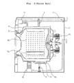
- Fig. 1 is a perspective view of a conventional drum washing machine
- Fig. 2 is a side view, in cross section, of the conventional drum washing machine.
- the conventional drum washing machine comprises: a casing 2 forming the exterior of the drum washing machine; a tub 6 disposed in the casing 2 in such a manner that the tub 6 is suspended by means of springs 4 and simultaneously supported by means of damper assemblies 5; a drum 8 rotatably mounted in the tub 6, in which clothes are put and into which wash water is supplied; a plurality of vanes 8a provided on the inner circumference of the drum 8 for lifting the clothes in the drum 8 as the drum 8 is rotated, the vanes 8a being longitudinally extended parallel to the axis of rotation of the drum 8 and inwardly protruded to a predetermined height while the vanes 8a are uniformly spaced apart from each other; and a motor 10 connected to the drum 8 in the rear of the tub 6 for rotating the drum 8.
- the drum washing machine further comprises: a water-supply valve assembly 12 mounted above the tub 6 for supplying wash water into the tub 6 and the drum 8; a detergent box assembly 14 also mounted above the tub 6 for supplying a detergent into the tub 6 and the drum 8; and a drainage pump assembly 16 mounted below the tub 6 for draining the wash water from the tub 6 and the drum 8.
- the drum 8 is provided at the inner circumference thereof with a plurality of through-holes 8h, through which the wash water flows between the drum 8 and the tub 6.
- the water-supply valve assembly 12 includes a water-supply valve (not shown) so that the water-supply valve assembly 12 supplies wash water into the tub 6 and the drum 8 when the water-supply valve is opened.
- the drainage pump assembly 16 includes a drainage pump (not shown) so that the drainage pump assembly 16 discharges the wash water from the tub 6 and the drum 8 when the drainage pump is operated.
- the tub 6 includes a heater mounting part 6a formed at the lower part thereof.
- the heater mounting part 6a of the tub 6 is downwardly extended from the tub 6 so that the heater 20 is mounted in the heater mounting part 6a.
- the heater 20 is slidably inserted into the heater mounting part 6a of the tub 6 from the front part thereof, and then securely fixed to the heater mounting part 6a of the tub 6.
- the water-supply valve When a washing process is performed while clothes are put in the drum 8, the water-supply valve is opened so that a proper amount of wash water is supplied into the tub 6 and the drum 8 depending upon the amount of the clothes.
- the wash water passes through the water-supply valve assembly 12, and then passes through the detergent box assembly 14.
- the wash water having passed through the detergent box assembly 14 is supplied into the tub 6 together with a detergent.
- the clothes are lifted to a predetermined height by the vanes 8a and then dropped from the vanes 8a so that the clothes can be washed by means of friction and impact.
- the heater 20 may be operated to heat the wash water in the tub 6 so that the washing efficiency is improved.
- the drainage pump is operated so that the wash water is discharged.
- the motor 10 is rotated at a high speed, and thus the drum 8 is also rotated at a high speed.
- the drum 8 is rotated, the wash water contained in the clothes is separated from the clothes by means of the centrifugal force of the drum 8. At this time, the wash water separated from the clothes is discharged through the through-holes 8h. In this way, an intermittent dewatering process is performed.
- the water-supply valve is opened again so that wash water is supplied into the tub 6 and the drum 8.
- the drum 8 is rotated so that a rinsing process is performed.
- the wash water is supplied into the tub 6 from the upper part thereof together with the detergent via the water-supply valve assembly 12 and the detergent box assembly 14, and the wash water supplied into the tub 6 is heated by the heater 20 mounted to the lower part of the tub 6.
- the wash water initially supplied into the tub is cold. Consequently, the wash water is slowly absorbed by the clothes.
- the conventional drum washing machine includes the heater mounting part 6a of the tub 6, which is provided so that the heater 20 is mounted in the tub 6.
- the heater mounting part 6a is formed at the lower part of the tub 6 in such a manner that the heater mounting part 6a is downwardly extended from the tub 6. Consequently, it is required to provide an additional space necessary for forming the heater mounting part 6a in the tub 6, which complicates construction of the drum washing machine.
- the wash water supplied in the tub 6 is heated by the heater 20. Since the heater 20 is mounted in the heater mounting part 6a of the tub 6, the wash water is also filled in the heater mounting part 6a of the tub 6, and thus the wash water filled in the heater mounting part 6a of the tub 6 is also heated. However, the wash water filled in the heater mounting part 6a of the tub 6 is not used to wash the clothes. Consequently, wash water and electric energy are uselessly wasted. In addition, the detergent is left with the wash water in the heater mounting part 6a of the tub 6, by which the washing efficiency of the drum washing machine is decreased.
- the present invention has been made in view of the above problems, and it is an object of the present invention to provide a steam jet drum washing machine which is capable of heating wash water and spraying the heated wash water into a tub and a drum of the washing machine in a phase of high-temperature and high-pressure steam, thereby rapidly soaking clothes in the wash water, reducing waste of the wash water and electric energy, and improving sterilizing and washing efficiencies of the drum washing machine.
- a steam jet drum washing machine comprising: a tub disposed in a casing and adapted so that wash water is supplied into the tub; a drum rotatably mounted in the tub and adapted so that clothes are put in the drum and the wash water is supplied into the drum; a water-supply unit disposed at one side of the tub for supplying the wash water into the tub and the drum; and a steam generator connected to the water-supply unit for heating the wash water to obtain high-temperature and high-pressure steam, and supplying the high-temperature and high-pressure steam into the tub and the drum.
- Fig. 3 is a perspective view of a steam jet drum washing machine according to a first preferred embodiment of the present invention
- Fig. 4 is a side view, in cross section, of the steam jet drum washing machine according to the first preferred embodiment of the present invention
- Fig. 5 is a perspective view, partially cutaway, of a steam generator of the present invention.
- the steam jet drum washing machine comprises: a casing 52 forming the exterior of the drum washing machine; a tub 56 disposed in the casing 52 in such a manner that the tub 56 is suspended by means of springs 54 and elastically supported by means of damper assemblies 55; a drum 58 rotatably mounted in the tub 56, in which clothes are put and into which wash water is supplied; a plurality of vanes 58a provided on the inner circumference of the drum 58 for lifting the clothes in the drum 58 as the drum 58 is rotated, the vanes 58a being longitudinally extended parallel to the axis of rotation of the drum 58 and inwardly protruded to a predetermined height while the vanes 58a are uniformly spaced apart from each other; a motor 60 connected to the drum 58 in the rear of the tub 56 for rotating the drum 58; and a steam generator 70 disposed above the tub 56 for heating the wash water to obtain high-temperature and high-pressure
- the drum washing machine further comprises: a water-supply unit 62 mounted above the tub 56 for supplying wash water into the tub 56 and the drum 58; and a drainage pump assembly 66 mounted below the tub 56 for draining the wash water from the tub 56 and the drum 58.
- the steam generator 70 is connected to the water-supply unit 62.
- the water-supply unit 62 comprises: a water-supply valve assembly 62a mounted to the rear of the casing 52 for supplying wash water; a detergent box assembly 62b mounted between the water-supply valve assembly 62a and the tub 56 for storing a detergent; a water-supply tube 62c connected between the water-supply valve assembly 62a and the steam generator 70; an auxiliary water-supply tube 62c' connected between the water-supply valve assembly 62a and the detergent box assembly 62b; and a steam tube 62d having one end connected to the steam generator 70 and the other end 62d' disposed in the tub 56 and the drum 58 for supplying the steam into the tub 56 and the drum 58.
- the water-supply unit 62 may comprise the water-supply valve assembly 62a, the water-supply tube 62c, and the steam tube 62d so that the wash water is supplied into the tub 56 and the drum 58 via only the steam generator 70.
- the drum 58 is provided at the inner circumference thereof with a plurality of through-holes 58h, through which the wash water flows between the drum 58 and the tub 56.
- the water-supply valve assembly 62 includes a water-supply valve (not shown) so that the water-supply valve assembly 62 supplies wash water into the tub 56 and the drum 58 when the water-supply valve is opened.
- the drainage pump assembly 66 includes a drainage pump (not shown) so that the drainage pump assembly 66 discharges the wash water from the tub 56 and the drum 58 when the drainage pump is operated.
- the water-supply tube 62c is connected between the water-supply valve assembly 62a and the steam generator 70 so that the wash water is supplied into the steam generator 70.
- the auxiliary water-supply tube 62c' is connected between the water-supply valve assembly 62a and the detergent box assembly 62b so that the wash water is supplied into the detergent box assembly 62b.
- the end 62d' of the steam tube 62d is formed in the shape of a nozzle so that steam is sprayed at a high speed from the end 62d'.
- the end 62d' of the steam tube 62d penetrates through the upper end of a gasket 57, which is made of rubber, for preventing leakage of water between the tub 56 and the casing 52. Consequently, the steam guided along the steam tube 62d is downwardly sprayed through the end 62d' of the steam tube 62d into the tub 56 and the drum 58.
- the water-supply tube 62c and the steam tube 62d are relatively short by the provision of the steam generator 70.
- the steam generator 70 is disposed above the tub 56 between the tub 56 and the casing 52 so that repair and inspection of the stem generator 70 can be easily and conveniently conducted.
- the steam generator 70 comprises: an airtight pressure container 72 connected at the top end thereof to the water-supply tube 62c and the steam tube 62d and having an inner space for storing wash water defined therein; a heater 74 mounted in the pressure container 72 for heating the wash water stored in the pressure container 72; an inlet valve 76a disposed between the water-supply tube 62c and the pressure container 72 for supplying the wash water into the pressure container 72; and an outlet valve 76b disposed between the steam tube 62d and the pressure container 72 for supplying steam into the steam tube 62d.
- the pressure container 72 comprises an upper container part 72a forming the upper part of the pressure container 72, and a lower container part 72b forming the lower part of the pressure container 72.
- the upper container part 72a and the lower container part 72b are preferably attached to each other by means of bolts (not shown).
- the inlet valve 76a and the outlet valve 76b are pressure valves that can be opened or closed depending upon the pressure inside the pressure container 72.
- the inlet valve 76a may be controlled either electrically or mechanically so that the inlet valve 76a is opened when the pressure inside the pressure container 72 is below a predetermined pressure.
- the outlet valve 76b may be controlled either electrically or mechanically so that the inlet valve 76a is opened when the pressure inside the pressure container 72 is over a predetermined pressure.
- the steam generator 70 further comprises: a water level sensor 77 disposed at the upper part of the pressure container 72 for sensing the amount of the wash water stored in the pressure container 72 to control the operation of the inlet valve 76a and the outlet valve 76b; and a temperature sensor 78 disposed at the lower part of the pressure container 72 for sensing the temperature inside the pressure container 72 to control the operation of the heater 74 on the basis of the temperature inside the pressure container 72.
- the water level sensor 77 senses the level of the wash water on the basis of the movement of a float on the wash water. Alternatively, the water level sensor 77 may sense the level of the wash water on the basis of the change in inside pressure of the pressure container 72 when the wash water is supplied into the pressure container 72.
- the heater 74 is horizontally disposed in the lower container part 72b so that heater 74 can be submerged under the wash water even when the wash water is supplied into the pressure container 72 to the minimum water level.
- the heater 74 is preferably formed in the shape of a curved pipe so that the heating surface area is increased.
- the heater 74 may be overheated while the heater 74 is energized. Consequently, there is preferably provided a safety unit for preventing overheating of the heater 74.
- the safety unit comprises: an automatic pressure switch 79a disposed by the side of the water level sensor 77 for cutting off the supply of electric current to the heater 74 to primarily stop the operation of the heater 74 when the pressure inside the pressure container 72 is over a predetermined pressure; and an automatic temperature switch 79b, such as a thermostat, disposed by the side of the temperature sensor 78 for cutting off the supply of electric current to the heater 74 to secondarily stop the operation of the heater 74 when the temperature inside the pressure container 72 is over a predetermined temperature.
- Additional automatic temperature switches 79b may be disposed for preventing overheating of the heater 74 when the automatic pressure switch 79a is not normally operated or when the pressure container 72 leaks.
- the steam generator 70 further comprises a thermal insulator 75, such as Styrofoam, for shielding the pressure container 72 to prevent thermal energy generated in the pressure container 72 from leaking out of the pressure container 72 when the heater 74 is operated.
- a thermal insulator 75 such as Styrofoam
- the operation of the heater 74, the inlet valve 76a, and the outlet valve 76b are controlled by a controller (not shown) for controlling the operation of the drum washing machine.
- Fig. 6 is a perspective view of a steam jet drum washing machine according to a second preferred embodiment of the present invention.
- the steam jet drum washing machine according to the second preferred embodiment of the present invention is identical to the steam jet drum washing machine according to the first preferred embodiment of the present invention except that the steam generator 70 is disposed below the tub 56 between the tub 56 and the casing 52, as shown in Fig. 6.
- the water-supply tube 63c connected between the steam generator 70 and the water-supply valve assembly (not shown) is disposed between one side of the tub 56 and the casing 52.
- the steam tube 63d connected between the steam generator 70 and the tub 56 is disposed between one side of the tub 56 and the casing 52.
- the water-supply valve When a washing process is performed while clothes are put in the drum 58, the water-supply valve is opened so that a proper amount of wash water is supplied into the tub 56 and the drum 58 depending upon the amount of the clothes.
- the wash water passes through the auxiliary water-supply tube 62c', and then passes through the detergent box assembly 62b.
- the wash water having passed through the detergent box assembly 62b is supplied into the tub 56 together with a detergent.
- the wash water passes through the water-supply tube 62c, and is then supplied into the steam generator 70 where the wash water is heated to obtain high-temperature and high-pressure steam.
- the high-temperature and high-pressure steam generated in the steam generator 70 is sprayed into the tub 56 and the drum 58 via the steam tube 62d.
- the water-supply valve when the water-supply valve is opened so that the wash water is supplied via the water-supply tube 62c, the wash water is supplied into the pressure container 72 while the inlet valve 76a and the outlet valve 76b are opened. As the wash water is supplied into the pressure container 72, the water level sensor 77 senses the level of the wash water in the pressure container 72.
- the inlet valve 76a is opened so that the wash water is supplied into the pressure container 72
- the outlet valve 76b is opened so that air is discharged from the pressure container 72.
- the inlet valve 76a and the outlet valve 76b are closed, and simultaneously the heater 74 is operated to heat the wash water so that high-temperature and high-pressure steam is generated.
- the heater 74 Since the heater 74 is operated in the airtight space in the pressure container 72, higher-temperature and higher-pressure steam may be generated as the heater 74 is operated for a longer time.
- the temperature sensor 78 senses the temperature of the interior of the pressure container 72, and the operation of the heater 74 is controlled on the basis of the sensed temperature so that the heater 74 is not overheated.
- the automatic pressure switch 79a and the automatic temperature switch 79b are operated to cut off the supply of electric current to the heater 74 so that overheating of the heater 74 is prevented.
- the wash water supplied into the airtight pressure container 72 is heated to generate high-temperature and high-pressure steam.
- the temperature sensor 78 senses that the temperature of the interior of the pressure container 72 is over a predetermined pressure
- the outlet valve 76b is opened so that the steam passes through the steam tube 62d and is then sprayed into the tub 56 and the drum 58.
- the water-supply valve When a proper amount of the wash water is supplied into the tub 56 and the drum 58, the water-supply valve is closed, and the motor 60 is operated. When the drum 58 is rotated by operation of the motor 60, the clothes are lifted to a predetermined height by the vanes 58a and then dropped from the vanes 58a. In this way, a washing process is performed.
- the drainage pump is operated so that the wash water is discharged.
- the motor 60 is rotated at a high speed, and thus the drum 58 is also rotated at a high speed.
- the drum 58 is rotated, the wash water contained in the clothes is separated from the clothes by means of the centrifugal force of the drum 58. In this way, an intermittent dewatering process is performed.
- the water-supply valve is opened again so that wash water is supplied into the tub 56 and the drum 58 to a predetermined level via the auxiliary water-supply tube 62c'. Thereafter, the drum 58 is rotated so that a rinsing process is performed.
- the wash water may be supplied into the steam generator 70 where the wash water is heated to obtain high-temperature and high-pressure steam, and the high-temperature and high-pressure steam may be sprayed into the tub 56 and the drum 58 even when the clothes are washed or rinsed as well as when the wash water is initially supplied into the tub 56 and the drum 58, in order to improve sterilizing and washing efficiencies of the drum washing machine.
- the present invention provides a steam jet drum washing machine characterized in that wash water is supplied into a steam generator where the wash water is heated to obtain high-temperature and high-pressure steam, and the steam is sprayed into a tub and a drum of the drum washing machine, thereby rapidly soaking clothes in the wash water when the wash water is initially supplied into the tub and the drum, saving wash water and electric energy. Furthermore, the wash water is supplied in a phase of high-temperature and high-pressure steam when clothes are washed and rinsed, whereby sterilizing and washing efficiencies of the drum washing machine are improved.
Abstract
Description
- The present invention relates to a drum washing machine which is capable of lifting clothes to a predetermined height and then dropping the lifted clothes so that the clothes can be washed by means of friction and impact, and more particularly to a steam jet drum washing machine which is capable of heating wash water and spraying the heated wash water into a tub and a drum of the washing machine in a phase of high-temperature and high-pressure steam, whereby sterilizing and washing efficiencies of the drum washing machine are improved.
- A drum washing machine is a kind of washer which is capable of washing clothes by friction between a drum rotated by a motor and the clothes put in the drum while a detergent and wash water are supplied in a horizontally mounted tub and the drum, which is disposed in the tub. With the drum washing machine, the clothes are neither damaged nor tangled with one another. Furthermore, the drum washing machine washes clothes by striking and rubbing the clothes, whereby washing efficiency is improved.
- Fig. 1 is a perspective view of a conventional drum washing machine, and Fig. 2 is a side view, in cross section, of the conventional drum washing machine.
- As shown in Figs. 1 and 2, the conventional drum washing machine comprises: a
casing 2 forming the exterior of the drum washing machine; atub 6 disposed in thecasing 2 in such a manner that thetub 6 is suspended by means ofsprings 4 and simultaneously supported by means ofdamper assemblies 5; adrum 8 rotatably mounted in thetub 6, in which clothes are put and into which wash water is supplied; a plurality ofvanes 8a provided on the inner circumference of thedrum 8 for lifting the clothes in thedrum 8 as thedrum 8 is rotated, thevanes 8a being longitudinally extended parallel to the axis of rotation of thedrum 8 and inwardly protruded to a predetermined height while thevanes 8a are uniformly spaced apart from each other; and amotor 10 connected to thedrum 8 in the rear of thetub 6 for rotating thedrum 8. - The drum washing machine further comprises: a water-
supply valve assembly 12 mounted above thetub 6 for supplying wash water into thetub 6 and thedrum 8; adetergent box assembly 14 also mounted above thetub 6 for supplying a detergent into thetub 6 and thedrum 8; and adrainage pump assembly 16 mounted below thetub 6 for draining the wash water from thetub 6 and thedrum 8. - The
drum 8 is provided at the inner circumference thereof with a plurality of through-holes 8h, through which the wash water flows between thedrum 8 and thetub 6. When thedrum 8 is rotated to dewater the clothes, the wash water contained in the clothes is separated from the clothes by means of the centrifugal force of thedrum 8. At this time, the wash water separated from the clothes is discharged through the through-holes 8h. The water-supply valve assembly 12 includes a water-supply valve (not shown) so that the water-supply valve assembly 12 supplies wash water into thetub 6 and thedrum 8 when the water-supply valve is opened. Similarly, thedrainage pump assembly 16 includes a drainage pump (not shown) so that thedrainage pump assembly 16 discharges the wash water from thetub 6 and thedrum 8 when the drainage pump is operated. - To the lower part of the
tub 6 is mounted aheater 20 for heating wash water in thetub 6 to a high temperature, by which the washing efficiency is improved. Specifically, thetub 6 includes aheater mounting part 6a formed at the lower part thereof. Theheater mounting part 6a of thetub 6 is downwardly extended from thetub 6 so that theheater 20 is mounted in theheater mounting part 6a. Theheater 20 is slidably inserted into theheater mounting part 6a of thetub 6 from the front part thereof, and then securely fixed to theheater mounting part 6a of thetub 6. - The operation of the conventional drum washing machine with the above-stated construction will now be described.
- When a washing process is performed while clothes are put in the
drum 8, the water-supply valve is opened so that a proper amount of wash water is supplied into thetub 6 and thedrum 8 depending upon the amount of the clothes. The wash water passes through the water-supply valve assembly 12, and then passes through thedetergent box assembly 14. The wash water having passed through thedetergent box assembly 14 is supplied into thetub 6 together with a detergent. - When the
drum 8 is rotated by operation of themotor 10, the clothes are lifted to a predetermined height by thevanes 8a and then dropped from thevanes 8a so that the clothes can be washed by means of friction and impact. At this time, theheater 20 may be operated to heat the wash water in thetub 6 so that the washing efficiency is improved. - After the washing process is finished, the drainage pump is operated so that the wash water is discharged. Subsequently, the
motor 10 is rotated at a high speed, and thus thedrum 8 is also rotated at a high speed. When thedrum 8 is rotated, the wash water contained in the clothes is separated from the clothes by means of the centrifugal force of thedrum 8. At this time, the wash water separated from the clothes is discharged through the through-holes 8h. In this way, an intermittent dewatering process is performed. Thereafter, the water-supply valve is opened again so that wash water is supplied into thetub 6 and thedrum 8. At the same time, thedrum 8 is rotated so that a rinsing process is performed. - The aforementioned rinsing and intermittent dewatering processes are alternately and repeatedly carried out, and finally a dewatering process is performed. In this way, a cleaning process comprising washing, rinsing, and dewatering processes is completed.
- In the conventional drum washing machine, however, the wash water is supplied into the
tub 6 from the upper part thereof together with the detergent via the water-supply valve assembly 12 and thedetergent box assembly 14, and the wash water supplied into thetub 6 is heated by theheater 20 mounted to the lower part of thetub 6. As can be easily understood from the above description, the wash water initially supplied into the tub is cold. Consequently, the wash water is slowly absorbed by the clothes. - The conventional drum washing machine includes the
heater mounting part 6a of thetub 6, which is provided so that theheater 20 is mounted in thetub 6. Theheater mounting part 6a is formed at the lower part of thetub 6 in such a manner that theheater mounting part 6a is downwardly extended from thetub 6. Consequently, it is required to provide an additional space necessary for forming theheater mounting part 6a in thetub 6, which complicates construction of the drum washing machine. - The wash water supplied in the
tub 6 is heated by theheater 20. Since theheater 20 is mounted in theheater mounting part 6a of thetub 6, the wash water is also filled in theheater mounting part 6a of thetub 6, and thus the wash water filled in theheater mounting part 6a of thetub 6 is also heated. However, the wash water filled in theheater mounting part 6a of thetub 6 is not used to wash the clothes. Consequently, wash water and electric energy are uselessly wasted. In addition, the detergent is left with the wash water in theheater mounting part 6a of thetub 6, by which the washing efficiency of the drum washing machine is decreased. - Therefore, the present invention has been made in view of the above problems, and it is an object of the present invention to provide a steam jet drum washing machine which is capable of heating wash water and spraying the heated wash water into a tub and a drum of the washing machine in a phase of high-temperature and high-pressure steam, thereby rapidly soaking clothes in the wash water, reducing waste of the wash water and electric energy, and improving sterilizing and washing efficiencies of the drum washing machine.
- In accordance with the present invention, the above and other objects can be accomplished by the provision of a steam jet drum washing machine comprising: a tub disposed in a casing and adapted so that wash water is supplied into the tub; a drum rotatably mounted in the tub and adapted so that clothes are put in the drum and the wash water is supplied into the drum; a water-supply unit disposed at one side of the tub for supplying the wash water into the tub and the drum; and a steam generator connected to the water-supply unit for heating the wash water to obtain high-temperature and high-pressure steam, and supplying the high-temperature and high-pressure steam into the tub and the drum.
- The above and other objects, features and other advantages of the present invention will be more clearly understood from the following detailed description taken in conjunction with the accompanying drawings, in which:
- Fig. 1 is a perspective view of a conventional drum washing machine;
- Fig. 2 is a side view, in cross section, of the conventional drum washing machine;
- Fig. 3 is a perspective view of a steam jet drum washing machine according to a first preferred embodiment of the present invention;
- Fig. 4 is a side view, in cross section, of the steam jet drum washing machine according to the first preferred embodiment of the present invention;
- Fig. 5 is a perspective view, partially cutaway, of a steam generator of the present invention; and
- Fig. 6 is a perspective view of a steam jet drum washing machine according to a second preferred embodiment of the present invention.
- Now, preferred embodiments of the present invention will be described in detail with reference to the accompanying drawings. In the drawings, the same or similar elements are denoted by the same reference numerals even though they are depicted in different drawings.
- Fig. 3 is a perspective view of a steam jet drum washing machine according to a first preferred embodiment of the present invention, Fig. 4 is a side view, in cross section, of the steam jet drum washing machine according to the first preferred embodiment of the present invention, and Fig. 5 is a perspective view, partially cutaway, of a steam generator of the present invention.
- As shown in Figs. 3 and 4, the steam jet drum washing machine according to the first preferred embodiment of the present invention comprises: a
casing 52 forming the exterior of the drum washing machine; atub 56 disposed in thecasing 52 in such a manner that thetub 56 is suspended by means ofsprings 54 and elastically supported by means ofdamper assemblies 55; adrum 58 rotatably mounted in thetub 56, in which clothes are put and into which wash water is supplied; a plurality ofvanes 58a provided on the inner circumference of thedrum 58 for lifting the clothes in thedrum 58 as thedrum 58 is rotated, thevanes 58a being longitudinally extended parallel to the axis of rotation of thedrum 58 and inwardly protruded to a predetermined height while thevanes 58a are uniformly spaced apart from each other; amotor 60 connected to thedrum 58 in the rear of thetub 56 for rotating thedrum 58; and asteam generator 70 disposed above thetub 56 for heating the wash water to obtain high-temperature and high-pressure steam, which is supplied to thetub 56 and thedrum 58. - The drum washing machine further comprises: a water-
supply unit 62 mounted above thetub 56 for supplying wash water into thetub 56 and thedrum 58; and adrainage pump assembly 66 mounted below thetub 56 for draining the wash water from thetub 56 and thedrum 58. Thesteam generator 70 is connected to the water-supply unit 62. - The water-
supply unit 62 comprises: a water-supply valve assembly 62a mounted to the rear of thecasing 52 for supplying wash water; adetergent box assembly 62b mounted between the water-supply valve assembly 62a and thetub 56 for storing a detergent; a water-supply tube 62c connected between the water-supply valve assembly 62a and thesteam generator 70; an auxiliary water-supply tube 62c' connected between the water-supply valve assembly 62a and thedetergent box assembly 62b; and asteam tube 62d having one end connected to thesteam generator 70 and theother end 62d' disposed in thetub 56 and thedrum 58 for supplying the steam into thetub 56 and thedrum 58. - Alternatively, the water-
supply unit 62 may comprise the water-supply valve assembly 62a, the water-supply tube 62c, and thesteam tube 62d so that the wash water is supplied into thetub 56 and thedrum 58 via only thesteam generator 70. - The
drum 58 is provided at the inner circumference thereof with a plurality of through-holes 58h, through which the wash water flows between thedrum 58 and thetub 56. When thedrum 58 is rotated to dewater the clothes, the wash water contained in the clothes is separated from the clothes by means of the centrifugal force of thedrum 58. At this time, the wash water separated from the clothes is discharged through the through-holes 58h. The water-supply valve assembly 62 includes a water-supply valve (not shown) so that the water-supply valve assembly 62 supplies wash water into thetub 56 and thedrum 58 when the water-supply valve is opened. Similarly, thedrainage pump assembly 66 includes a drainage pump (not shown) so that thedrainage pump assembly 66 discharges the wash water from thetub 56 and thedrum 58 when the drainage pump is operated. - The water-
supply tube 62c is connected between the water-supply valve assembly 62a and thesteam generator 70 so that the wash water is supplied into thesteam generator 70. The auxiliary water-supply tube 62c' is connected between the water-supply valve assembly 62a and thedetergent box assembly 62b so that the wash water is supplied into thedetergent box assembly 62b. - The
end 62d' of thesteam tube 62d is formed in the shape of a nozzle so that steam is sprayed at a high speed from theend 62d'. Theend 62d' of thesteam tube 62d penetrates through the upper end of agasket 57, which is made of rubber, for preventing leakage of water between thetub 56 and thecasing 52. Consequently, the steam guided along thesteam tube 62d is downwardly sprayed through theend 62d' of thesteam tube 62d into thetub 56 and thedrum 58. - The water-
supply tube 62c and thesteam tube 62d are relatively short by the provision of thesteam generator 70. Thesteam generator 70 is disposed above thetub 56 between thetub 56 and thecasing 52 so that repair and inspection of thestem generator 70 can be easily and conveniently conducted. - As shown in Fig. 5, the
steam generator 70 comprises: anairtight pressure container 72 connected at the top end thereof to the water-supply tube 62c and thesteam tube 62d and having an inner space for storing wash water defined therein; aheater 74 mounted in thepressure container 72 for heating the wash water stored in thepressure container 72; aninlet valve 76a disposed between the water-supply tube 62c and thepressure container 72 for supplying the wash water into thepressure container 72; and anoutlet valve 76b disposed between thesteam tube 62d and thepressure container 72 for supplying steam into thesteam tube 62d. - The
pressure container 72 comprises anupper container part 72a forming the upper part of thepressure container 72, and alower container part 72b forming the lower part of thepressure container 72. Theupper container part 72a and thelower container part 72b are preferably attached to each other by means of bolts (not shown). - The
inlet valve 76a and theoutlet valve 76b are pressure valves that can be opened or closed depending upon the pressure inside thepressure container 72. Theinlet valve 76a may be controlled either electrically or mechanically so that theinlet valve 76a is opened when the pressure inside thepressure container 72 is below a predetermined pressure. Similarly, theoutlet valve 76b may be controlled either electrically or mechanically so that theinlet valve 76a is opened when the pressure inside thepressure container 72 is over a predetermined pressure. - The
steam generator 70 further comprises: awater level sensor 77 disposed at the upper part of thepressure container 72 for sensing the amount of the wash water stored in thepressure container 72 to control the operation of theinlet valve 76a and theoutlet valve 76b; and atemperature sensor 78 disposed at the lower part of thepressure container 72 for sensing the temperature inside thepressure container 72 to control the operation of theheater 74 on the basis of the temperature inside thepressure container 72. - The
water level sensor 77 senses the level of the wash water on the basis of the movement of a float on the wash water. Alternatively, thewater level sensor 77 may sense the level of the wash water on the basis of the change in inside pressure of thepressure container 72 when the wash water is supplied into thepressure container 72. - The
heater 74 is horizontally disposed in thelower container part 72b so thatheater 74 can be submerged under the wash water even when the wash water is supplied into thepressure container 72 to the minimum water level. - The
heater 74 is preferably formed in the shape of a curved pipe so that the heating surface area is increased. Theheater 74 may be overheated while theheater 74 is energized. Consequently, there is preferably provided a safety unit for preventing overheating of theheater 74. - The safety unit comprises: an
automatic pressure switch 79a disposed by the side of thewater level sensor 77 for cutting off the supply of electric current to theheater 74 to primarily stop the operation of theheater 74 when the pressure inside thepressure container 72 is over a predetermined pressure; and anautomatic temperature switch 79b, such as a thermostat, disposed by the side of thetemperature sensor 78 for cutting off the supply of electric current to theheater 74 to secondarily stop the operation of theheater 74 when the temperature inside thepressure container 72 is over a predetermined temperature. - Additional
automatic temperature switches 79b may be disposed for preventing overheating of theheater 74 when theautomatic pressure switch 79a is not normally operated or when thepressure container 72 leaks. - The
steam generator 70 further comprises athermal insulator 75, such as Styrofoam, for shielding thepressure container 72 to prevent thermal energy generated in thepressure container 72 from leaking out of thepressure container 72 when theheater 74 is operated. - In the
steam generator 70 with the above-stated construction, the operation of theheater 74, theinlet valve 76a, and theoutlet valve 76b are controlled by a controller (not shown) for controlling the operation of the drum washing machine. - Fig. 6 is a perspective view of a steam jet drum washing machine according to a second preferred embodiment of the present invention.
- The steam jet drum washing machine according to the second preferred embodiment of the present invention is identical to the steam jet drum washing machine according to the first preferred embodiment of the present invention except that the
steam generator 70 is disposed below thetub 56 between thetub 56 and thecasing 52, as shown in Fig. 6. - Consequently, the water-
supply tube 63c connected between thesteam generator 70 and the water-supply valve assembly (not shown) is disposed between one side of thetub 56 and thecasing 52. Similarly, thesteam tube 63d connected between thesteam generator 70 and thetub 56 is disposed between one side of thetub 56 and thecasing 52. - When the
steam generator 70 is disposed below thetub 56 as described above, an empty space defined below thetub 56 between thetub 56 and thecasing 52 may be used as the installation space for thesteam generator 70. Consequently, the total size of the drum washing machine is not increased even though thesteam generator 70 is mounted in the drum washing machine. - The operation of the steam jet drum washing machine with the above-stated construction according to the present invention will now be described.
- When a washing process is performed while clothes are put in the
drum 58, the water-supply valve is opened so that a proper amount of wash water is supplied into thetub 56 and thedrum 58 depending upon the amount of the clothes. The wash water passes through the auxiliary water-supply tube 62c', and then passes through thedetergent box assembly 62b. The wash water having passed through thedetergent box assembly 62b is supplied into thetub 56 together with a detergent. - When the wash water is to be sprayed in a phase of steam according to a user's selection, the wash water passes through the water-
supply tube 62c, and is then supplied into thesteam generator 70 where the wash water is heated to obtain high-temperature and high-pressure steam. The high-temperature and high-pressure steam generated in thesteam generator 70 is sprayed into thetub 56 and thedrum 58 via thesteam tube 62d. - Specifically, when the water-supply valve is opened so that the wash water is supplied via the water-
supply tube 62c, the wash water is supplied into thepressure container 72 while theinlet valve 76a and theoutlet valve 76b are opened. As the wash water is supplied into thepressure container 72, thewater level sensor 77 senses the level of the wash water in thepressure container 72. - At this time, the
inlet valve 76a is opened so that the wash water is supplied into thepressure container 72, and theoutlet valve 76b is opened so that air is discharged from thepressure container 72. - When a proper amount of the wash water is supplied into the
pressure container 72, theinlet valve 76a and theoutlet valve 76b are closed, and simultaneously theheater 74 is operated to heat the wash water so that high-temperature and high-pressure steam is generated. - Since the
heater 74 is operated in the airtight space in thepressure container 72, higher-temperature and higher-pressure steam may be generated as theheater 74 is operated for a longer time. - At this time, the
temperature sensor 78 senses the temperature of the interior of thepressure container 72, and the operation of theheater 74 is controlled on the basis of the sensed temperature so that theheater 74 is not overheated. - When the
temperature sensor 78 is out of order or abnormally operated, theautomatic pressure switch 79a and theautomatic temperature switch 79b are operated to cut off the supply of electric current to theheater 74 so that overheating of theheater 74 is prevented. - When the
heater 74 is operated, the wash water supplied into theairtight pressure container 72 is heated to generate high-temperature and high-pressure steam. When thetemperature sensor 78 senses that the temperature of the interior of thepressure container 72 is over a predetermined pressure, theoutlet valve 76b is opened so that the steam passes through thesteam tube 62d and is then sprayed into thetub 56 and thedrum 58. - At this time, the steam is sprayed into the
tub 56 and thedrum 58 through theend 62d' of the steam tube, which is formed in the shape of a nozzle. As a result, the clothes are rapidly soaked. - When a proper amount of the wash water is supplied into the
tub 56 and thedrum 58, the water-supply valve is closed, and themotor 60 is operated. When thedrum 58 is rotated by operation of themotor 60, the clothes are lifted to a predetermined height by thevanes 58a and then dropped from thevanes 58a. In this way, a washing process is performed. - After the washing process is finished, the drainage pump is operated so that the wash water is discharged. Subsequently, the
motor 60 is rotated at a high speed, and thus thedrum 58 is also rotated at a high speed. When thedrum 58 is rotated, the wash water contained in the clothes is separated from the clothes by means of the centrifugal force of thedrum 58. In this way, an intermittent dewatering process is performed. The water-supply valve is opened again so that wash water is supplied into thetub 56 and thedrum 58 to a predetermined level via the auxiliary water-supply tube 62c'. Thereafter, thedrum 58 is rotated so that a rinsing process is performed. - The aforementioned rinsing and intermittent dewatering processes are alternately and repeatedly carried out, and finally a dewatering process is performed. In this way, a process for cleaning the clothes is completed.
- It should be noted that the wash water may be supplied into the
steam generator 70 where the wash water is heated to obtain high-temperature and high-pressure steam, and the high-temperature and high-pressure steam may be sprayed into thetub 56 and thedrum 58 even when the clothes are washed or rinsed as well as when the wash water is initially supplied into thetub 56 and thedrum 58, in order to improve sterilizing and washing efficiencies of the drum washing machine. - As apparent from the above description, the present invention provides a steam jet drum washing machine characterized in that wash water is supplied into a steam generator where the wash water is heated to obtain high-temperature and high-pressure steam, and the steam is sprayed into a tub and a drum of the drum washing machine, thereby rapidly soaking clothes in the wash water when the wash water is initially supplied into the tub and the drum, saving wash water and electric energy. Furthermore, the wash water is supplied in a phase of high-temperature and high-pressure steam when clothes are washed and rinsed, whereby sterilizing and washing efficiencies of the drum washing machine are improved.
- Although the preferred embodiments of the present invention have been disclosed for illustrative purposes, those skilled in the art will appreciate that various modifications, additions and substitutions are possible, without departing from the scope and spirit of the invention as disclosed in the accompanying claims.
Claims (8)
- A washing method for a steam jet washing machine comprising:a water supplying step for supplying wash water into a tub;a steam supplying step for supplying steam into a drum by operating a steam generator; anda drum driving step for driving the drum.
- The washing method for the steam jet washing machine of claim 1, wherein the steam supplying step for supplying steam into a drum by operating a steam generator and the drum driving step for driving the drum are performed after completing the water supplying step for supplying wash water into a tub.
- The washing method for the steam jet washing machine of claim 1, wherein the steam supplying step for supplying steam into a drum by operating a steam generator and the drum driving step for driving the drum are performed simultaneously.
- The washing method for the steam jet washing machine of claim 1, wherein the steam supplying step comprises:a water supplying step for supplying wash water into the steam generator;a heater driving step for driving a heater of the steam generator to generate steam; anda steam spraying step for spraying steam into the drum.
- A washing method for a steam jet washing machine comprising a tub disposed within a cabinet and adapted so that wash water is supplied into the tub; a drum rotatably mounted in the tub and adapted so that wash water is supplied into the tub; a water-supply unit disposed at one side of the tub for supplying the wash water into the tub and the drum; and a steam generator connected to the water-supply unit for heating the wash water to obtain high-temperature and high-pressure, and supplying the high-temperature and high pressure steam into the tub and the drum, comprising:a water supplying step for supplying wash water into the tub;a steam supplying step for supplying steam into the drum by operating the steam generator; anda drum driving step for driving the drum.
- The washing method for a steam jet washing machine of claim 5, wherein the steam supplying step for supplying steam into the drum by operating the steam generator and the drum driving step for driving the drum are performed after completing the water supplying step for supplying wash water into the tub.
- The washing method for a steam jet washing machine of claim 5, wherein the steam supplying step for supplying steam into the drum by operating the steam generator and the drum driving step for driving the drum are performed simultaneously.
- The washing method for a steam jet washing machine of claim 5, wherein the steam supplying step for supplying steam into the drum by operating the steam generator comprises:a water supplying step for supplying wash water into the steam generator;a heater driving step for driving a heater of the steam generator to generate steam; anda steam spraying step for spraying steam into the drum.
Applications Claiming Priority (2)
| Application Number | Priority Date | Filing Date | Title |
|---|---|---|---|
| KR10-2003-0020204A KR100510680B1 (en) | 2003-03-31 | 2003-03-31 | Drum washer by spray steam |
| EP04000337.8A EP1464751B2 (en) | 2003-03-31 | 2004-01-09 | Steam jet drum washing machine |
Related Parent Applications (2)
| Application Number | Title | Priority Date | Filing Date |
|---|---|---|---|
| EP04000337.8A Division EP1464751B2 (en) | 2003-03-31 | 2004-01-09 | Steam jet drum washing machine |
| EP04000337.8A Division-Into EP1464751B2 (en) | 2003-03-31 | 2004-01-09 | Steam jet drum washing machine |
Publications (3)
| Publication Number | Publication Date |
|---|---|
| EP1746194A2 true EP1746194A2 (en) | 2007-01-24 |
| EP1746194A3 EP1746194A3 (en) | 2008-09-17 |
| EP1746194B1 EP1746194B1 (en) | 2018-09-05 |
Family
ID=36918367
Family Applications (3)
| Application Number | Title | Priority Date | Filing Date |
|---|---|---|---|
| EP06022219.7A Expired - Lifetime EP1746194B1 (en) | 2003-03-31 | 2004-01-09 | Washing method for steam jet washing machine |
| EP04000337.8A Expired - Lifetime EP1464751B2 (en) | 2003-03-31 | 2004-01-09 | Steam jet drum washing machine |
| EP06022220.5A Expired - Lifetime EP1746195B1 (en) | 2003-03-31 | 2004-01-09 | Steam jet drum washing machine |
Family Applications After (2)
| Application Number | Title | Priority Date | Filing Date |
|---|---|---|---|
| EP04000337.8A Expired - Lifetime EP1464751B2 (en) | 2003-03-31 | 2004-01-09 | Steam jet drum washing machine |
| EP06022220.5A Expired - Lifetime EP1746195B1 (en) | 2003-03-31 | 2004-01-09 | Steam jet drum washing machine |
Country Status (6)
| Country | Link |
|---|---|
| US (3) | US7490493B2 (en) |
| EP (3) | EP1746194B1 (en) |
| JP (1) | JP2004298616A (en) |
| KR (1) | KR100510680B1 (en) |
| CN (3) | CN1818188B (en) |
| DE (1) | DE602004021450D1 (en) |
Families Citing this family (127)
| Publication number | Priority date | Publication date | Assignee | Title |
|---|---|---|---|---|
| US8844160B2 (en) | 1997-04-29 | 2014-09-30 | Whirlpool Corporation | Modular fabric revitalizing system |
| US20070151312A1 (en) * | 2005-12-30 | 2007-07-05 | Bruce Beihoff C | Modular fabric revitalizing system |
| KR100504501B1 (en) | 2003-04-14 | 2005-08-02 | 엘지전자 주식회사 | Drum washer's washing method by spray steam |
| EP1651093B1 (en) * | 2003-07-30 | 2016-09-07 | BSH Hausgeräte GmbH | Method for operating a dishwasher with at least one partial programme step of drying |
| KR20050017490A (en) * | 2003-08-13 | 2005-02-22 | 엘지전자 주식회사 | Method for generating steam in Drum-type washing machine |
| KR100531379B1 (en) * | 2003-08-13 | 2005-11-28 | 엘지전자 주식회사 | Method for smoothing wrinkles of laundry in Drum-type washing machine |
| KR100540749B1 (en) * | 2003-08-13 | 2006-01-10 | 엘지전자 주식회사 | Steam generator for drum-type washing machine |
| US7600402B2 (en) * | 2003-11-04 | 2009-10-13 | Lg Electronics Inc. | Washing apparatus and control method thereof |
| KR100595555B1 (en) * | 2004-05-13 | 2006-07-03 | 엘지전자 주식회사 | Steam injection type washing machine and temperature correction method thereof |
| US8276230B2 (en) * | 2004-05-31 | 2012-10-02 | Lg Electronics Inc. | Operating method of laundry device |
| WO2006001612A1 (en) * | 2004-06-23 | 2006-01-05 | Lg Electronics Inc. | Washing machine and method thereof |
| EP1616990B1 (en) * | 2004-07-13 | 2017-08-30 | LG Electronics, Inc. | Washing machine with steam generation apparatus |
| KR100739544B1 (en) * | 2005-02-28 | 2007-07-18 | 엘지전자 주식회사 | Apparatus for Spraying Steam in Washing machine |
| US20060096333A1 (en) * | 2004-11-05 | 2006-05-11 | Samsung Electronics Co., Ltd. | Steam generating device and washing machine having the same |
| KR100621697B1 (en) * | 2004-11-05 | 2006-09-19 | 삼성전자주식회사 | Washing machine with steam generator |
| KR100745418B1 (en) * | 2004-11-16 | 2007-08-02 | 삼성전자주식회사 | Control method of washing machine having steam generation |
| KR20060055222A (en) * | 2004-11-18 | 2006-05-23 | 삼성전자주식회사 | Washing machine and control method thereof |
| KR20060061974A (en) * | 2004-12-02 | 2006-06-09 | 삼성전자주식회사 | Apparatus for remove wrinkles of clothes and method thereof |
| KR101186595B1 (en) | 2005-02-28 | 2012-09-27 | 엘지전자 주식회사 | coupling structure of steam generator in washing device |
| AU2006223786B2 (en) | 2005-03-16 | 2008-10-02 | Lg Electronics Inc. | Washing machine using steam and method for controlling the same |
| KR20060100604A (en) * | 2005-03-17 | 2006-09-21 | 엘지전자 주식회사 | Apparatus for spraying steam in washing machine |
| KR100751408B1 (en) * | 2005-03-17 | 2007-08-23 | 엘지전자 주식회사 | Apparatus for spraying steam in washing machine ? Method for cleaning as the same |
| KR100753506B1 (en) * | 2005-03-17 | 2007-08-31 | 엘지전자 주식회사 | Water level sensor of apparatus for spraying steam in washing machine |
| KR100826176B1 (en) * | 2005-03-22 | 2008-04-30 | 엘지전자 주식회사 | control method for washing machine |
| KR100531328B1 (en) * | 2005-03-25 | 2005-11-29 | 엘지전자 주식회사 | Control method of drum type washing machine |
| KR100744514B1 (en) * | 2005-03-25 | 2007-08-01 | 엘지전자 주식회사 | operating method in washing machine |
| AU2006225475B2 (en) | 2005-03-25 | 2009-05-21 | Lg Electronics Inc. | Method for washing of washer |
| AU2006225458B2 (en) * | 2005-03-25 | 2009-04-23 | Lg Electronics Inc. | Laundry machine and method for controlling the same |
| KR100808174B1 (en) * | 2005-03-25 | 2008-03-03 | 엘지전자 주식회사 | steam generator for drum type washing machine |
| KR100672322B1 (en) * | 2005-03-25 | 2007-01-24 | 엘지전자 주식회사 | Operating method in Washing machine |
| DE602006019559D1 (en) * | 2005-03-25 | 2011-02-24 | Lg Electronics Inc | METHOD FOR CONTROLLING THE OPERATION OF A WASHING MACHINE |
| KR100672371B1 (en) * | 2005-03-25 | 2007-01-24 | 엘지전자 주식회사 | Operating method in washing machine |
| KR100672367B1 (en) * | 2005-03-25 | 2007-01-24 | 엘지전자 주식회사 | Method for washing by steam in drum type washer |
| KR100808176B1 (en) * | 2005-03-25 | 2008-02-29 | 엘지전자 주식회사 | steam generator for drum type washing machine |
| KR20060102950A (en) * | 2005-03-25 | 2006-09-28 | 엘지전자 주식회사 | Drum type washing machine |
| KR100672526B1 (en) | 2005-03-25 | 2007-01-24 | 엘지전자 주식회사 | Washing device and method thereof |
| DE112006000045B4 (en) * | 2005-03-25 | 2020-01-30 | Lg Electronics Inc. | Operating method for a laundry machine |
| KR100808175B1 (en) * | 2005-03-25 | 2008-02-29 | 엘지전자 주식회사 | drum type washing machine |
| DE602006012942D1 (en) | 2005-03-25 | 2010-04-29 | Lg Electronics Inc | STEAM GENERATOR AND WASHING APPARATUS AND METHOD THEREFOR |
| KR100765278B1 (en) * | 2005-04-04 | 2007-10-09 | 엘지전자 주식회사 | Washer with Aroma Sprayer |
| KR20060120818A (en) * | 2005-05-23 | 2006-11-28 | 엘지전자 주식회사 | Steam generator having thermostat for drum washing machine and contrl method as the same |
| KR101253126B1 (en) * | 2005-05-23 | 2013-04-10 | 엘지전자 주식회사 | Water Level Sensor of Apparatus for Spraying Steam in Drum type Washer |
| KR101216073B1 (en) * | 2005-05-23 | 2012-12-26 | 엘지전자 주식회사 | steam generator for washing machine |
| WO2006126803A2 (en) * | 2005-05-23 | 2006-11-30 | Lg Electronics Inc. | Laundry device |
| KR101154962B1 (en) * | 2005-05-23 | 2012-06-18 | 엘지전자 주식회사 | steam generator having press-sensor for drum washing machine and contrl method as the same |
| EP1885935B1 (en) * | 2005-05-31 | 2019-09-04 | LG Electronics Inc. | A method for controlling a washing machine |
| US8438755B2 (en) * | 2005-05-31 | 2013-05-14 | Lg Electronics Inc. | Laundry machine |
| KR100833857B1 (en) * | 2005-05-31 | 2008-06-02 | 엘지전자 주식회사 | Washing machine |
| KR100751765B1 (en) * | 2005-07-01 | 2007-08-24 | 주식회사 대우일렉트로닉스 | Drum type washing machine having steam injection apparatus |
| KR101215347B1 (en) * | 2005-08-29 | 2012-12-26 | 엘지전자 주식회사 | steam generator for drum washing machine and control method as the same |
| US9663894B2 (en) * | 2005-11-10 | 2017-05-30 | Lg Electronics Inc. | Steam generator and laundry dryer having the same and controlling method thereof |
| US7934280B2 (en) † | 2005-11-11 | 2011-05-03 | Lg Electronics Inc. | Drum-type washing machine and tub cleaning method of the same |
| WO2007058477A1 (en) * | 2005-11-15 | 2007-05-24 | Lg Electronics, Inc. | Apparatus of supplying and dicharging fluid and method of operating the same |
| US20070151041A1 (en) * | 2005-12-30 | 2007-07-05 | Mcallister Karl D | Control process for a revitalizing appliance |
| US20070163097A1 (en) * | 2005-12-30 | 2007-07-19 | Metcalfe Ld | Low absorbency pad system for a fabric treatment appliance |
| US7665227B2 (en) * | 2005-12-30 | 2010-02-23 | Whirlpool Corporation | Fabric revitalizing method using low absorbency pads |
| US20070163096A1 (en) * | 2005-12-30 | 2007-07-19 | Mcallister Karl D | Fluid delivery system for a fabric treatment appliance |
| US20070163095A1 (en) * | 2005-12-30 | 2007-07-19 | Mcallister Karl D | Fabric revitalizing system and treatment appliance |
| US7921578B2 (en) | 2005-12-30 | 2011-04-12 | Whirlpool Corporation | Nebulizer system for a fabric treatment appliance |
| US7735345B2 (en) * | 2005-12-30 | 2010-06-15 | Whirlpool Corporation | Automatic fabric treatment appliance with a manual fabric treatment station |
| US20070163094A1 (en) * | 2005-12-30 | 2007-07-19 | Tremitchell Wright | Fabric revitalizing method using mist |
| KR101215447B1 (en) * | 2006-01-03 | 2012-12-26 | 삼성전자주식회사 | Washing machine |
| KR20070078320A (en) * | 2006-01-26 | 2007-07-31 | 삼성전자주식회사 | Washing machine and method of controlling the same |
| KR101233164B1 (en) * | 2006-01-26 | 2013-02-15 | 엘지전자 주식회사 | Steam generator and washing machine using the same |
| KR20070078329A (en) * | 2006-01-26 | 2007-07-31 | 엘지전자 주식회사 | Steam generator and washing machine using the same |
| KR101139250B1 (en) | 2006-01-26 | 2012-05-14 | 삼성전자주식회사 | Washing machine with steam generator and method using the same |
| KR20070078328A (en) * | 2006-01-26 | 2007-07-31 | 엘지전자 주식회사 | Steam generator and washing machine using the same |
| KR100762337B1 (en) * | 2006-03-29 | 2007-10-02 | 주식회사 대우일렉트로닉스 | Steam device of washing machine and control method thereof |
| CN100503941C (en) * | 2006-06-07 | 2009-06-24 | 南京乐金熊猫电器有限公司 | Washing method of washing device |
| US20070283728A1 (en) * | 2006-06-09 | 2007-12-13 | Nyik Siong Wong | Prevention of scale and sludge in a steam generator of a fabric treatment appliance |
| US7765628B2 (en) | 2006-06-09 | 2010-08-03 | Whirlpool Corporation | Steam washing machine operation method having a dual speed spin pre-wash |
| US7941885B2 (en) | 2006-06-09 | 2011-05-17 | Whirlpool Corporation | Steam washing machine operation method having dry spin pre-wash |
| US20070283509A1 (en) * | 2006-06-09 | 2007-12-13 | Nyik Siong Wong | Draining liquid from a steam generator of a fabric treatment appliance |
| US7627920B2 (en) | 2006-06-09 | 2009-12-08 | Whirlpool Corporation | Method of operating a washing machine using steam |
| US7730568B2 (en) | 2006-06-09 | 2010-06-08 | Whirlpool Corporation | Removal of scale and sludge in a steam generator of a fabric treatment appliance |
| KR101265601B1 (en) * | 2006-06-27 | 2013-05-22 | 엘지전자 주식회사 | steam generator |
| KR100793800B1 (en) * | 2006-06-30 | 2008-01-11 | 엘지전자 주식회사 | Washing machine and control method of steam generator for the same |
| US7591859B2 (en) * | 2006-08-15 | 2009-09-22 | Whirlpool Corporation | Water supply control for a steam generator of a fabric treatment appliance using a weight sensor |
| US20080041120A1 (en) * | 2006-08-15 | 2008-02-21 | Nyik Siong Wong | Fabric Treatment Appliance with Anti-Siphoning |
| US7841219B2 (en) | 2006-08-15 | 2010-11-30 | Whirlpool Corporation | Fabric treating appliance utilizing steam |
| US20080040869A1 (en) * | 2006-08-15 | 2008-02-21 | Nyik Siong Wong | Determining Fabric Temperature in a Fabric Treating Appliance |
| US7886392B2 (en) | 2006-08-15 | 2011-02-15 | Whirlpool Corporation | Method of sanitizing a fabric load with steam in a fabric treatment appliance |
| US7707859B2 (en) * | 2006-08-15 | 2010-05-04 | Whirlpool Corporation | Water supply control for a steam generator of a fabric treatment appliance |
| US7665332B2 (en) | 2006-08-15 | 2010-02-23 | Whirlpool Corporation | Steam fabric treatment appliance with exhaust |
| US7681418B2 (en) | 2006-08-15 | 2010-03-23 | Whirlpool Corporation | Water supply control for a steam generator of a fabric treatment appliance using a temperature sensor |
| US7753009B2 (en) | 2006-10-19 | 2010-07-13 | Whirlpool Corporation | Washer with bio prevention cycle |
| US20080095660A1 (en) * | 2006-10-19 | 2008-04-24 | Nyik Siong Wong | Method for treating biofilm in an appliance |
| WO2008056841A1 (en) * | 2006-11-10 | 2008-05-15 | Lg Electronics, Inc. | Method for refreshing clothes |
| KR101341461B1 (en) * | 2006-12-15 | 2013-12-16 | 엘지전자 주식회사 | Steam laundry dryer |
| EP1959043B1 (en) * | 2007-02-19 | 2018-11-14 | Electrolux Home Products Corporation N.V. | Domestic appliance with external water supply |
| US8393183B2 (en) | 2007-05-07 | 2013-03-12 | Whirlpool Corporation | Fabric treatment appliance control panel and associated steam operations |
| ATE505582T1 (en) * | 2007-05-09 | 2011-04-15 | Lg Electronics Inc | WASHING MACHINE |
| EP2009167A3 (en) * | 2007-05-25 | 2009-08-12 | Daewoo Electronics Corporation | Washing machine and steam washing method thereof |
| DE102007028618A1 (en) | 2007-06-19 | 2009-01-02 | Miele & Cie. Kg | A method of operating a laundry treating machine with steam generating means and laundry treating machine |
| DE102007028617B4 (en) | 2007-06-19 | 2010-10-28 | Miele & Cie. Kg | Front-loadable laundry treatment machine with steam generator |
| CN100545339C (en) * | 2007-07-06 | 2009-09-30 | 南京乐金熊猫电器有限公司 | A kind of washing methods of removing anaphylactogen |
| DE102008035787B4 (en) * | 2007-08-03 | 2023-07-20 | Lg Electronics Inc. | Steam generator and clothes treatment machine and dishwasher with a steam generator |
| US7690062B2 (en) | 2007-08-31 | 2010-04-06 | Whirlpool Corporation | Method for cleaning a steam generator |
| US7861343B2 (en) | 2007-08-31 | 2011-01-04 | Whirlpool Corporation | Method for operating a steam generator in a fabric treatment appliance |
| US8555675B2 (en) | 2007-08-31 | 2013-10-15 | Whirlpool Corporation | Fabric treatment appliance with steam backflow device |
| US8037565B2 (en) | 2007-08-31 | 2011-10-18 | Whirlpool Corporation | Method for detecting abnormality in a fabric treatment appliance having a steam generator |
| US8555676B2 (en) | 2007-08-31 | 2013-10-15 | Whirlpool Corporation | Fabric treatment appliance with steam backflow device |
| US7905119B2 (en) | 2007-08-31 | 2011-03-15 | Whirlpool Corporation | Fabric treatment appliance with steam generator having a variable thermal output |
| US7918109B2 (en) | 2007-08-31 | 2011-04-05 | Whirlpool Corporation | Fabric Treatment appliance with steam generator having a variable thermal output |
| US7966683B2 (en) | 2007-08-31 | 2011-06-28 | Whirlpool Corporation | Method for operating a steam generator in a fabric treatment appliance |
| JP5107684B2 (en) * | 2007-11-28 | 2012-12-26 | ハイアール グループ コーポレーション | Washing and drying machine |
| US8966944B2 (en) | 2008-08-01 | 2015-03-03 | Lg Electronics Inc. | Control method of a laundry machine |
| US9416478B2 (en) | 2009-03-31 | 2016-08-16 | Lg Electronics Inc. | Washing machine and washing method |
| RU2480542C2 (en) | 2009-02-11 | 2013-04-27 | ЭлДжи ЭЛЕКТРОНИКС ИНК. | Method of washing and washing machine |
| KR20100129161A (en) | 2009-05-28 | 2010-12-08 | 엘지전자 주식회사 | Laundry machine |
| US8302431B2 (en) * | 2009-06-03 | 2012-11-06 | Green Solution, Inc. | Method and apparatus for using steam in a commercial laundry machine as an environmentally-friendly replacement of conventional dry cleaning or wet cleaning processes |
| EP2264240B1 (en) | 2009-06-18 | 2011-06-15 | Miele & Cie. KG | Front loaded laundry treatment machine with steam creation device |
| ATE541980T1 (en) | 2009-06-25 | 2012-02-15 | Miele & Cie | STEAM GENERATING DEVICE FOR A LAUNDRY TREATMENT MACHINE AND LAUNDRY TREATMENT MACHINE |
| US9234307B2 (en) | 2009-07-27 | 2016-01-12 | Lg Electronics Inc. | Control method of a laundry machine |
| US10533275B2 (en) | 2009-07-27 | 2020-01-14 | Lg Electronics Inc. | Control method of a laundry machine |
| US9822473B2 (en) | 2009-07-27 | 2017-11-21 | Lg Electronics Inc. | Control method of a laundry machine |
| US9695537B2 (en) | 2009-07-27 | 2017-07-04 | Lg Electronics Inc. | Control method of a laundry machine |
| US9045853B2 (en) * | 2009-10-13 | 2015-06-02 | Lg Electronics Inc. | Laundry treating apparatus |
| US8776297B2 (en) | 2009-10-13 | 2014-07-15 | Lg Electronics Inc. | Laundry treating apparatus and method |
| CN103205873A (en) * | 2013-04-01 | 2013-07-17 | 慈溪市小金鱼电器厂 | Washing machine |
| CN106702676B (en) * | 2015-07-27 | 2020-11-10 | 青岛海尔滚筒洗衣机有限公司 | Steam generation device for washing machine and washing machine |
| CN105544148B (en) * | 2016-01-22 | 2018-01-16 | 珠海格力电器股份有限公司 | Inner tank of washing machine and washing machine |
| CN110042619B (en) * | 2018-01-15 | 2022-04-12 | 青岛海尔洗涤电器有限公司 | Clothes treatment method for clothes treatment equipment and clothes treatment equipment |
| CN110144702A (en) * | 2019-06-13 | 2019-08-20 | 东莞市双盈精密五金制品有限公司 | A kind of steam washing machine |
| CN110974109B (en) * | 2019-11-25 | 2022-01-28 | 佛山市顺德区美的洗涤电器制造有限公司 | Steam generator and dish washing machine |
| CN114045634B (en) * | 2021-11-30 | 2022-12-16 | 珠海格力电器股份有限公司 | Steam generator and clothes treatment device comprising same |
| WO2023157468A1 (en) * | 2022-02-18 | 2023-08-24 | パナソニックIpマネジメント株式会社 | Garment treatment device |
Citations (4)
| Publication number | Priority date | Publication date | Assignee | Title |
|---|---|---|---|---|
| GB799788A (en) | 1956-02-03 | 1958-08-13 | Erich Sulzmann | Improvements in or relating to the laundering of textile articles |
| GB1222227A (en) | 1968-07-13 | 1971-02-10 | Poensgen Gmbh Geb | Improvements in or relating to washing and spin-drying |
| JPH04158896A (en) | 1990-10-22 | 1992-06-01 | Sanyo Electric Co Ltd | Fully automatic washing machine |
| JP2003019382A (en) | 2001-07-09 | 2003-01-21 | Mitsubishi Electric Corp | Washing machine |
Family Cites Families (73)
| Publication number | Priority date | Publication date | Assignee | Title |
|---|---|---|---|---|
| DE604415C (en) * | ||||
| US1755101A (en) * | 1921-12-16 | 1930-04-15 | Mills G Clark | Dishwasher |
| US1501746A (en) * | 1923-03-31 | 1924-07-15 | Martin W Carter | Washing machine |
| US1570552A (en) * | 1924-04-05 | 1926-01-19 | Bowerbank John Wainwright | Combined boiling, washing, condensing, and drying machine |
| US1852179A (en) * | 1926-05-11 | 1932-04-05 | Thomas J Mcdonald | Steam washing machine |
| US1755746A (en) * | 1926-12-02 | 1930-04-22 | Perrera Altitolo | Pocket lighter |
| US1946278A (en) | 1931-06-10 | 1934-02-06 | Elfving Thore Martin | Washing machine |
| US1999446A (en) * | 1933-10-06 | 1935-04-30 | James K Delano | Transformer coupled induction heater |
| FR992852A (en) * | 1944-09-14 | 1951-10-24 | Washing machine | |
| US2574098A (en) * | 1946-01-11 | 1951-11-06 | Fraraccio Pasco | Centrifugal cleaning and drying machine |
| US2431246A (en) * | 1946-01-25 | 1947-11-18 | Edwin R Hallanan | Domestic washing machine for clothes, dishes, and the like |
| US2664094A (en) * | 1947-08-01 | 1953-12-29 | Spragins John Harris | Dishwasher |
| US2880300A (en) * | 1953-02-06 | 1959-03-31 | Reimers Electric Appliance Co | Electrically-heated steam generators |
| US3025381A (en) * | 1959-02-09 | 1962-03-13 | Walter E Pickering | Steam generator |
| US3129361A (en) * | 1959-02-12 | 1964-04-14 | Philco Corp | Control mechanism for laundering equipment |
| US3203013A (en) * | 1964-04-06 | 1965-08-31 | Ametek Inc | Laundry method |
| US3410986A (en) * | 1965-03-15 | 1968-11-12 | David W. Groom | Electric steam generator |
| US3402576A (en) * | 1966-02-28 | 1968-09-24 | Michael R. Krupsky | Combination clothes washer, dryer, dishwasher, drycleaner, and garment appearance-finishing machine |
| US3347066A (en) * | 1966-09-15 | 1967-10-17 | Alvin S Klausner | Washing machine or the like with adjustable programming controls |
| US3443406A (en) * | 1967-02-28 | 1969-05-13 | Ametek Inc | Washing machine with fluid injection through openings in drum |
| FR1531485A (en) * | 1967-05-03 | 1968-07-05 | Method of cleaning, in particular of textile articles, and of equipment allowing the implementation | |
| US3615822A (en) * | 1968-12-09 | 1971-10-26 | Kingsland Drum & Barrel Co Inc | Methods and apparatus for cleaning drums |
| US3730682A (en) * | 1971-01-25 | 1973-05-01 | Staphex Corp | Sterilization system for clothes treating machines and method of using |
| US4287407A (en) * | 1978-08-17 | 1981-09-01 | Hobart Corporation | Tank flushing delay arrangement for a steam generator |
| US4207683A (en) * | 1979-02-01 | 1980-06-17 | Horton Roberta J | Clothes dryer |
| US4471792A (en) * | 1981-11-24 | 1984-09-18 | Lpw Reinigungstechnik Gmbh | Apparatus for the treatment of articles with a volatile liquid |
| JPS58137427A (en) * | 1982-02-12 | 1983-08-15 | Mitsubishi Heavy Ind Ltd | Method for controlling operation of dust collecting apparatus in exhaust gas treating system |
| DE3230764C2 (en) * | 1982-08-16 | 1985-04-04 | Jörg 8500 Nürnberg Danneberg | Process for finishing and / or drying textile pieces |
| JPS5995A (en) | 1983-06-20 | 1984-01-05 | 三洋電機株式会社 | Full automatic washer |
| JPS61128995A (en) | 1984-11-26 | 1986-06-17 | 三洋電機株式会社 | Washing machine |
| US5361322A (en) * | 1988-12-21 | 1994-11-01 | Dov Z Glucksman | Ejector tube humidifier for blowerless mixing of air and steam |
| JP2639045B2 (en) * | 1989-01-27 | 1997-08-06 | 松下電器産業株式会社 | Washing machine with sterilization and miticide function |
| US4941333A (en) | 1989-01-31 | 1990-07-17 | Levi Strauss & Co. | Centrifugally draining single drum washing machine |
| US5180438A (en) * | 1989-10-11 | 1993-01-19 | Hockh Metall-Reinigungsanlagen Gmbh | Cleaning and drying system |
| US5255840A (en) * | 1989-12-26 | 1993-10-26 | Praxair Technology, Inc. | Fluxless solder coating and joining |
| JP2746485B2 (en) | 1991-07-23 | 1998-05-06 | シャープ株式会社 | Fully automatic washing and drying machine |
| NL9002305A (en) | 1990-10-23 | 1992-05-18 | Shell Int Research | METHOD FOR UNPARAFINIFICATION. |
| US5215043A (en) * | 1991-02-19 | 1993-06-01 | Mitsui Mining Company, Ltd. | Steam generator for a steam bath |
| US5219371A (en) * | 1992-03-27 | 1993-06-15 | Shim Kyong S | Dry cleaning system and method having steam injection |
| IT1254981B (en) * | 1992-06-19 | 1995-10-11 | WASHING AND STERILIZATION APPARATUS OF RUBBER CAPS, OR SIMILAR APPLICABLE IN PHARMACEUTICAL PACKAGES | |
| US5390385A (en) | 1993-05-28 | 1995-02-21 | Knight Equipment International | Laundry management system for washing machines |
| GB9319857D0 (en) | 1993-09-25 | 1993-11-10 | Groves Paul A | Kitchen appliance |
| JP3067510B2 (en) | 1993-12-17 | 2000-07-17 | シャープ株式会社 | Drum type fully automatic washing machine |
| US5425255A (en) * | 1994-02-10 | 1995-06-20 | Eaton Corporation | Washing machine fill system |
| FR2723970B1 (en) * | 1994-08-09 | 1996-09-20 | Ilsa Spa | PROCESS FOR CLEANING IN A LIQUID MEDIUM PARTS OF FABRICS OR CLOTHING AND THE APPLICATION OF ITS IMPLEMENTATION |
| IT1267603B1 (en) | 1994-12-13 | 1997-02-07 | Zanussi Elettrodomestici | WASHING MACHINES WITH PERFECTED DEVICES FOR DETERMINING THE TYPE OF FABRIC |
| DE4447160A1 (en) * | 1994-12-29 | 1996-07-04 | Bosch Siemens Hausgeraete | Washing machine with a detergent dispenser |
| BE1009718A6 (en) * | 1995-10-20 | 1997-07-01 | Peeters Tom Walter | Washing machine. |
| DE874580T1 (en) | 1995-12-05 | 1999-06-02 | Ken Maskinfabrik A S | METHOD FOR DISINFECTING THE WASHING SPACE OF AN AUTOMATIC DISHWASHER AND AUTOMATIC DISHWASHER FOR CARRYING OUT THE METHOD |
| US5962288A (en) * | 1996-03-06 | 1999-10-05 | Belloch Corp. | Method for treating biological cells in a degassed medium by rapid heating |
| FR2745896B1 (en) * | 1996-03-07 | 1998-04-24 | Armines | METHOD AND INSTALLATION FOR DRYING A MASS OF WET FIBROUS MATERIAL, IN PARTICULAR A LAUNDRY MASS |
| KR0157747B1 (en) | 1996-03-30 | 1999-01-15 | 배순훈 | Humidifier operating control method |
| FR2750709B1 (en) | 1996-07-05 | 1998-10-30 | Esswein Sa | HEATING METHOD AND DEVICE FOR A DRYING WASHING MACHINE |
| US5989203A (en) * | 1996-08-02 | 1999-11-23 | Wang; Chun-Chung | Steam massaging device |
| DE19641309B4 (en) † | 1996-10-08 | 2014-07-31 | Electrolux Rothenburg Gmbh Factory And Development | drum washing machine |
| JP3907770B2 (en) * | 1997-02-25 | 2007-04-18 | 東静電気株式会社 | Method and apparatus for reclaiming futons |
| DE19743508A1 (en) * | 1997-10-01 | 1999-04-08 | Bosch Siemens Hausgeraete | Heating washing solution in washing machine |
| JPH11226290A (en) * | 1998-02-16 | 1999-08-24 | Takeshi Murakami | Vacuum-sterilizing and washing method of washing machine |
| GB2337274B (en) * | 1998-05-12 | 2001-10-17 | Notetry Ltd | Method and apparatus for agitating the contents of a container |
| US6854300B2 (en) * | 1998-05-12 | 2005-02-15 | Dyson Limited | Method and apparatus for containing and agitating the contents of a container |
| JP4354558B2 (en) * | 1998-12-16 | 2009-10-28 | 有限会社ネオフィールド | Cleaning method and cleaning device |
| GB2358641B (en) * | 1999-03-25 | 2002-10-09 | John Herbert North | Improved washing machine |
| SE521337C2 (en) * | 1999-08-09 | 2003-10-21 | Electrolux Ab | Textile washing machine with steam drying |
| US6299076B1 (en) * | 2000-03-10 | 2001-10-09 | Jeffrey E. Sloan | Steam cleaning system |
| KR20010088208A (en) * | 2000-03-11 | 2001-09-26 | 구자홍 | Balancer with Drum Washing Machine |
| US7021087B2 (en) * | 2000-06-05 | 2006-04-04 | Procter & Gamble Company | Methods and apparatus for applying a treatment fluid to fabrics |
| US6811811B2 (en) * | 2001-05-04 | 2004-11-02 | Procter & Gamble Company | Method for applying a treatment fluid to fabrics |
| US6691536B2 (en) | 2000-06-05 | 2004-02-17 | The Procter & Gamble Company | Washing apparatus |
| US6434857B1 (en) * | 2000-07-05 | 2002-08-20 | Smartclean Jv | Combination closed-circuit washer and drier |
| JP2002360987A (en) † | 2001-06-05 | 2002-12-17 | Matsushita Electric Ind Co Ltd | Washing and drying machine |
| CH695383A5 (en) * | 2001-07-10 | 2006-04-28 | V Zug Ag | Dryer or washing machine with steamer. |
| JP4784029B2 (en) * | 2001-09-21 | 2011-09-28 | パナソニック株式会社 | Washing machine |
| KR20050065722A (en) | 2003-12-23 | 2005-06-30 | 삼성전자주식회사 | Washing machine and control method thereof |
-
2003
- 2003-03-31 KR KR10-2003-0020204A patent/KR100510680B1/en active IP Right Grant
-
2004
- 2004-01-09 EP EP06022219.7A patent/EP1746194B1/en not_active Expired - Lifetime
- 2004-01-09 DE DE602004021450T patent/DE602004021450D1/en not_active Expired - Lifetime
- 2004-01-09 EP EP04000337.8A patent/EP1464751B2/en not_active Expired - Lifetime
- 2004-01-09 US US10/753,496 patent/US7490493B2/en active Active
- 2004-01-09 EP EP06022220.5A patent/EP1746195B1/en not_active Expired - Lifetime
- 2004-01-17 CN CN2006100070616A patent/CN1818188B/en not_active Expired - Lifetime
- 2004-01-17 CN CNB2004100028605A patent/CN1303278C/en not_active Expired - Lifetime
- 2004-01-17 CN CN2006100070601A patent/CN1818187B/en not_active Expired - Lifetime
- 2004-01-21 JP JP2004013356A patent/JP2004298616A/en active Pending
-
2007
- 2007-02-06 US US11/702,620 patent/US7520146B2/en not_active Expired - Lifetime
- 2007-02-06 US US11/702,630 patent/US7661169B2/en not_active Expired - Lifetime
Patent Citations (4)
| Publication number | Priority date | Publication date | Assignee | Title |
|---|---|---|---|---|
| GB799788A (en) | 1956-02-03 | 1958-08-13 | Erich Sulzmann | Improvements in or relating to the laundering of textile articles |
| GB1222227A (en) | 1968-07-13 | 1971-02-10 | Poensgen Gmbh Geb | Improvements in or relating to washing and spin-drying |
| JPH04158896A (en) | 1990-10-22 | 1992-06-01 | Sanyo Electric Co Ltd | Fully automatic washing machine |
| JP2003019382A (en) | 2001-07-09 | 2003-01-21 | Mitsubishi Electric Corp | Washing machine |
Also Published As
| Publication number | Publication date |
|---|---|
| EP1746194B1 (en) | 2018-09-05 |
| DE602004021450D1 (en) | 2009-07-23 |
| EP1464751A1 (en) | 2004-10-06 |
| EP1746195A2 (en) | 2007-01-24 |
| CN1818187A (en) | 2006-08-16 |
| EP1746195B1 (en) | 2016-07-27 |
| US7490493B2 (en) | 2009-02-17 |
| CN1818188B (en) | 2011-12-28 |
| CN1818187B (en) | 2012-02-29 |
| EP1464751B1 (en) | 2009-06-10 |
| US20070137262A1 (en) | 2007-06-21 |
| US7661169B2 (en) | 2010-02-16 |
| US7520146B2 (en) | 2009-04-21 |
| US20040187527A1 (en) | 2004-09-30 |
| EP1464751B2 (en) | 2015-02-25 |
| EP1746195A3 (en) | 2008-11-19 |
| CN1818188A (en) | 2006-08-16 |
| US20070136956A1 (en) | 2007-06-21 |
| JP2004298616A (en) | 2004-10-28 |
| EP1746194A3 (en) | 2008-09-17 |
| CN1534128A (en) | 2004-10-06 |
| KR100510680B1 (en) | 2005-08-31 |
| KR20040085507A (en) | 2004-10-08 |
| CN1303278C (en) | 2007-03-07 |
Similar Documents
| Publication | Publication Date | Title |
|---|---|---|
| EP1746194A2 (en) | Steam jet drum washing machine | |
| EP2107153B1 (en) | Drum washing machine | |
| KR101003358B1 (en) | Washing machine | |
| KR100504501B1 (en) | Drum washer's washing method by spray steam | |
| KR100763386B1 (en) | Control Method of The Washing Machine | |
| KR101003359B1 (en) | Drum type washing machine and washing method thereof | |
| KR100686031B1 (en) | Control Method for washing course by spray steam in drum type washer | |
| EP2602379B1 (en) | Laundry washing machine | |
| KR100517612B1 (en) | Drum washer by spray steam | |
| EP1507032B1 (en) | Washing method and washing machine with steam generator | |
| KR20060055222A (en) | Washing machine and control method thereof | |
| KR20050065721A (en) | Washing machine | |
| KR20060094998A (en) | Control method of the washing machine | |
| WO2006126813A2 (en) | Steam generator and washing machine having the same | |
| KR100531330B1 (en) | washing method for dual spraying type drum washer | |
| US20050028295A1 (en) | Method for controlling drum-type washing machine | |
| KR20050044884A (en) | Steam spraying type drum washer | |
| KR20050043874A (en) | Washing method for steam injection type drum washer | |
| KR100672590B1 (en) | Operating method in washing machine | |
| KR100531331B1 (en) | dual spraying type washer | |
| KR20060024026A (en) | Washing method for steam injection type drum washer |
Legal Events
| Date | Code | Title | Description |
|---|---|---|---|
| PUAI | Public reference made under article 153(3) epc to a published international application that has entered the european phase |
Free format text: ORIGINAL CODE: 0009012 |
|
| 17P | Request for examination filed |
Effective date: 20061024 |
|
| AC | Divisional application: reference to earlier application |
Ref document number: 1464751 Country of ref document: EP Kind code of ref document: P |
|
| AK | Designated contracting states |
Kind code of ref document: A2 Designated state(s): DE FR GB |
|
| RIN1 | Information on inventor provided before grant (corrected) |
Inventor name: OH, SOO YOUNG Inventor name: JEON, SI MOON Inventor name: WOO, KYUNG CHUL Inventor name: KIM, JIN WOONG |
|
| PUAL | Search report despatched |
Free format text: ORIGINAL CODE: 0009013 |
|
| AK | Designated contracting states |
Kind code of ref document: A3 Designated state(s): DE FR GB |
|
| AKX | Designation fees paid |
Designated state(s): DE FR GB |
|
| 17Q | First examination report despatched |
Effective date: 20140430 |
|
| REG | Reference to a national code |
Ref country code: DE Ref legal event code: R079 Ref document number: 602004053154 Country of ref document: DE Free format text: PREVIOUS MAIN CLASS: D06F0039080000 Ipc: D06F0039000000 |
|
| GRAP | Despatch of communication of intention to grant a patent |
Free format text: ORIGINAL CODE: EPIDOSNIGR1 |
|
| RIC1 | Information provided on ipc code assigned before grant |
Ipc: D06F 39/00 20060101AFI20180216BHEP |
|
| INTG | Intention to grant announced |
Effective date: 20180326 |
|
| RAP1 | Party data changed (applicant data changed or rights of an application transferred) |
Owner name: LG ELECTRONICS INC. |
|
| GRAS | Grant fee paid |
Free format text: ORIGINAL CODE: EPIDOSNIGR3 |
|
| GRAA | (expected) grant |
Free format text: ORIGINAL CODE: 0009210 |
|
| AC | Divisional application: reference to earlier application |
Ref document number: 1464751 Country of ref document: EP Kind code of ref document: P |
|
| AK | Designated contracting states |
Kind code of ref document: B1 Designated state(s): DE FR GB |
|
| REG | Reference to a national code |
Ref country code: GB Ref legal event code: FG4D |
|
| REG | Reference to a national code |
Ref country code: DE Ref legal event code: R096 Ref document number: 602004053154 Country of ref document: DE |
|
| REG | Reference to a national code |
Ref country code: DE Ref legal event code: R097 Ref document number: 602004053154 Country of ref document: DE |
|
| PLBE | No opposition filed within time limit |
Free format text: ORIGINAL CODE: 0009261 |
|
| STAA | Information on the status of an ep patent application or granted ep patent |
Free format text: STATUS: NO OPPOSITION FILED WITHIN TIME LIMIT |
|
| 26N | No opposition filed |
Effective date: 20190606 |
|
| GBPC | Gb: european patent ceased through non-payment of renewal fee |
Effective date: 20190109 |
|
| PG25 | Lapsed in a contracting state [announced via postgrant information from national office to epo] |
Ref country code: FR Free format text: LAPSE BECAUSE OF NON-PAYMENT OF DUE FEES Effective date: 20190131 |
|
| PG25 | Lapsed in a contracting state [announced via postgrant information from national office to epo] |
Ref country code: GB Free format text: LAPSE BECAUSE OF NON-PAYMENT OF DUE FEES Effective date: 20190109 |
|
| PGFP | Annual fee paid to national office [announced via postgrant information from national office to epo] |
Ref country code: DE Payment date: 20221205 Year of fee payment: 20 |
|
| P01 | Opt-out of the competence of the unified patent court (upc) registered |
Effective date: 20230524 |
|
| REG | Reference to a national code |
Ref country code: DE Ref legal event code: R071 Ref document number: 602004053154 Country of ref document: DE |