EP1745904A2 - Method for the forming of ceramic tiles or slabs reproducing the typical characteristics of the natural stones and related apparatus - Google Patents
Method for the forming of ceramic tiles or slabs reproducing the typical characteristics of the natural stones and related apparatus Download PDFInfo
- Publication number
- EP1745904A2 EP1745904A2 EP06076158A EP06076158A EP1745904A2 EP 1745904 A2 EP1745904 A2 EP 1745904A2 EP 06076158 A EP06076158 A EP 06076158A EP 06076158 A EP06076158 A EP 06076158A EP 1745904 A2 EP1745904 A2 EP 1745904A2
- Authority
- EP
- European Patent Office
- Prior art keywords
- powders
- container
- compressed air
- layer
- air flow
- Prior art date
- Legal status (The legal status is an assumption and is not a legal conclusion. Google has not performed a legal analysis and makes no representation as to the accuracy of the status listed.)
- Withdrawn
Links
Images


Classifications
-
- B—PERFORMING OPERATIONS; TRANSPORTING
- B28—WORKING CEMENT, CLAY, OR STONE
- B28B—SHAPING CLAY OR OTHER CERAMIC COMPOSITIONS; SHAPING SLAG; SHAPING MIXTURES CONTAINING CEMENTITIOUS MATERIAL, e.g. PLASTER
- B28B13/00—Feeding the unshaped material to moulds or apparatus for producing shaped articles; Discharging shaped articles from such moulds or apparatus
- B28B13/02—Feeding the unshaped material to moulds or apparatus for producing shaped articles
- B28B13/0215—Feeding the moulding material in measured quantities from a container or silo
-
- B—PERFORMING OPERATIONS; TRANSPORTING
- B28—WORKING CEMENT, CLAY, OR STONE
- B28B—SHAPING CLAY OR OTHER CERAMIC COMPOSITIONS; SHAPING SLAG; SHAPING MIXTURES CONTAINING CEMENTITIOUS MATERIAL, e.g. PLASTER
- B28B1/00—Producing shaped prefabricated articles from the material
- B28B1/005—Devices or processes for obtaining articles having a marble appearance
Definitions
- the present invention refers to a method for the forming of ceramic tiles or slabs reproducing the typical characteristics of the natural stones and a related apparatus.
- the present invention refers to a method and related apparatus for the forming of ceramic tiles or slabs reproducing the typical visible aspects of the natural stones, altering the prearranged veining arrangement in powders forming a layer to be compacted.
- Object of the present invention is that of providing a method and related apparatus which permits satisfying the aforesaid needs and overcoming at the same time the drawbacks mentioned with reference to the prior art.
- the apparatus comprises, in its most general form, a container adapted to contain a layer 100 of coloured powders to be compacted having a prearranged arrangement and compressed air blowing means adapted to insert an air flow inside the container through at least one hole 3, so to locally alter the prearranged arrangement of the powders.
- the hole has a very small diameter in relation to the thickness, so to have a reduced air flow rate at high speed.
- the layer 100 is conveyed towards forming means adapted to compact the powders.
- the container is a carriage 20 adapted to move atop a surface 30 between a back position (Fig. 1), wherein it receives (by not illustrated, prior art means) the coloured powders which form at its interior the layer 100 to be compacted, having a substantially constant thickness S, and an advanced position, not illustrated, wherein it loads a forming cavity 50 of the tile.
- the carriage 20 laterally has the hole 3, through which the compressed air is inserted (Fig. 2). Although only one hole 3 is illustrated it is possible to foresee several holes through which compressed air is blown, also arranged on opposite sides.
- the compressed air blowing means is a compressed air blower, schematised in figure 2 and indicated with 2.
- the insertion pressure of the compressed air can be adjusted with known means, such as an electric valve 4 which intercepts the air input conduit.
- a movable plate 20b associated with the carriage 20 and adapted to slide in relation to it so to be able to close the lower opening, as is visible in figure 2.
- This embodiment is well adapted for carriages 20 containing a great volume of powders; however, for reduced volumes it is possible that the powders can exit during the insertion of compressed air, through the upper opening which has been left open. In such case, it is possible to foresee the use, in association with the lower plate 20b, of a further plate 20a adapted to close the upper opening of the carriage 20 (Figs.1A,2A).
- the exit of the air inserted in the carriage 20 closed by both plates 20a,20b, the wall of the carriage 20 opposite to that from which the air is inserted is provided with an air discharge valve, not illustrated.
- valve With respect to the insertion hole, situated on the opposite wall, determines the progression of the line of air in the powders and therefore the position of the "crack" marked by the broken line in the figures.
- the carriage is brought towards the forming cavity 50 according to the prior art, and subsequently the lower plate 20b, and if present the upper plate 20a, accompany the carriage 20 until they arrive above the mould cavity 50, then the plates 20a,20b are removed to permit the loading of the powder in the mould. If the used plate has a high thickness, it may be removed from the carriage 20 at the edge of the mould.
- the pressure of the compressed air can be adjusted as desired, as a function of the desired aesthetic effect.
- operation takes place at a pressure in the range of 0.2 - 6 bars through a hole having a diameter in the range of 1 - 8 mm.
- the container is a vertical hopper 40 with a loading opening 6 above and an unloading opening 7 below.
- the hopper 40 is placed above a horizontal movable surface 10 and has a parallelepiped conformation with the two faces 40a,40b with larger surface placed perpendicular to the advancing direction of the movable surface 10, indicated with an arrow in Fig. 4, and therefore with the remaining two opposite vertical faces 40c,40d placed parallel to the advancing direction of the surface 10.
- the distance between the two faces 40a,40b with larger surface is preferably equal to the thickness S of the layer 100 of powders to be compacted.
- the distance between the unloading opening 7 and the underlying movable surface 10 is equal to that of the thickness S of the layer 100 to be compacted, so that the exit speed of the powders from the hopper is approximately equal to that of the movable surface 10.
- the compressed air flow is preferably inserted in a substantially horizontal direction.
- the method and apparatus for the forming of ceramic tiles or slabs reproducing the typical characteristics of the natural stones according to the present invention permits satisfying the needs and overcoming the drawbacks as stated in the introductive part of the present description with reference to the prior art.
Landscapes
- Engineering & Computer Science (AREA)
- Manufacturing & Machinery (AREA)
- Chemical & Material Sciences (AREA)
- Ceramic Engineering (AREA)
- Mechanical Engineering (AREA)
- Devices For Post-Treatments, Processing, Supply, Discharge, And Other Processes (AREA)
- Press-Shaping Or Shaping Using Conveyers (AREA)
- Aftertreatments Of Artificial And Natural Stones (AREA)
Abstract
Description
- The present invention refers to a method for the forming of ceramic tiles or slabs reproducing the typical characteristics of the natural stones and a related apparatus.
- More in particular, the present invention refers to a method and related apparatus for the forming of ceramic tiles or slabs reproducing the typical visible aspects of the natural stones, altering the prearranged veining arrangement in powders forming a layer to be compacted.
- As is known, there exist methods and related systems at the state of the art which are capable of achieving tiles reproducing aesthetic effects very close to those present in the natural stones.
- One of these systems is described in the application PCT/IB2005/000025 of the same applicant.
- The drawback encountered by applying the methods and the systems of the known art is the difficulty to faithfully recreate, on the finished tiles, in addition to the normal veining, also those typical discontinuous decorative motifs caused by particular natural phenomena, such as those which cause a "crack" or irregular displacements of the veining.
- There is therefore a great need to have available a method and related apparatus for the forming of ceramic tiles or slabs reproducing the typical characteristics of the natural stones which permits obtaining a final tile having an arrangement of the veining altered, so to also reproduce the discontinuous decorative motifs caused by particular natural phenomena, such as for example a crack.
- Object of the present invention is that of providing a method and related apparatus which permits satisfying the aforesaid needs and overcoming at the same time the drawbacks mentioned with reference to the prior art.
- Such object is attained by means of a method and related apparatus in accordance with the
claims 1 and 8, respectively. - The dependent claims outline preferred and particularly advantageous embodiments of the method and the apparatus according to the invention.
- Further characteristics and advantages of the invention shall be evident from the reading of the following description, provided as exemplifying and not limiting, with the aid of the figures illustrated in the attached tables, wherein:
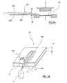
- Figures 1 and 1A show a schematic view in vertical section of an apparatus for the forming of ceramic tiles or slabs reproducing the typical characteristics of the natural stones, in accordance with a first embodiment of the present invention;
- Figures 2 and 2A show a perspective view of a detail of figure 1 and 1A, respectively;
- Figure 3 shows a front view, partially in section, of the apparatus in accordance with a second embodiment of the present invention;
- Figure 4 shows a view taken along the line IV-IV of figure 3.
- In the figures, an apparatus is shown for the forming of ceramic tiles or slabs reproducing the typical characteristics of the natural stones, in accordance with the present invention.
- The apparatus comprises, in its most general form, a container adapted to contain a
layer 100 of coloured powders to be compacted having a prearranged arrangement and compressed air blowing means adapted to insert an air flow inside the container through at least onehole 3, so to locally alter the prearranged arrangement of the powders. - The hole has a very small diameter in relation to the thickness, so to have a reduced air flow rate at high speed.
- At the end of the alteration of the powders, with respect to their prearranged arrangement, the
layer 100 is conveyed towards forming means adapted to compact the powders. - In accordance with a first embodiment of the present invention, the container is a
carriage 20 adapted to move atop asurface 30 between a back position (Fig. 1), wherein it receives (by not illustrated, prior art means) the coloured powders which form at its interior thelayer 100 to be compacted, having a substantially constant thickness S, and an advanced position, not illustrated, wherein it loads a formingcavity 50 of the tile. - The
carriage 20 laterally has thehole 3, through which the compressed air is inserted (Fig. 2). Although only onehole 3 is illustrated it is possible to foresee several holes through which compressed air is blown, also arranged on opposite sides. - The compressed air blowing means is a compressed air blower, schematised in figure 2 and indicated with 2.
- The insertion pressure of the compressed air can be adjusted with known means, such as an
electric valve 4 which intercepts the air input conduit. - Essentially, by blowing compressed air within the
carriage 20, the powders present at its interior undergo a local remixing, with consequent interruption at the blow point of the previously achieved graphics. This generates alayer 100 having, at the point wherein it was operated, an effect similar to a crack. - In order to avoid the undesired exit of the powders present in the
carriage 20 during the compressed air insertion, it is necessary that at least the lower opening of thecarriage 20 is closed. - To such end, the use is foreseen of a
movable plate 20b associated with thecarriage 20 and adapted to slide in relation to it so to be able to close the lower opening, as is visible in figure 2. - This embodiment is well adapted for
carriages 20 containing a great volume of powders; however, for reduced volumes it is possible that the powders can exit during the insertion of compressed air, through the upper opening which has been left open. In such case, it is possible to foresee the use, in association with thelower plate 20b, of afurther plate 20a adapted to close the upper opening of the carriage 20 (Figs.1A,2A). - In order to permit, in the variant of the first embodiment just described, the exit of the air inserted in the
carriage 20 closed by bothplates carriage 20 opposite to that from which the air is inserted is provided with an air discharge valve, not illustrated. - The positioning of the valve with respect to the insertion hole, situated on the opposite wall, determines the progression of the line of air in the powders and therefore the position of the "crack" marked by the broken line in the figures.
- At the end of the compressed air insertion, the carriage is brought towards the forming
cavity 50 according to the prior art, and subsequently thelower plate 20b, and if present theupper plate 20a, accompany thecarriage 20 until they arrive above themould cavity 50, then theplates carriage 20 at the edge of the mould. - Alternatively, it is possible to not use any lower plate, and to rest the
carriage 20 directly atop thesurface 30 which in this case must be flush with the mould, which will have the lower punch raised when thecarriage 20 is brought over the mould. - The pressure of the compressed air can be adjusted as desired, as a function of the desired aesthetic effect. Preferably, operation takes place at a pressure in the range of 0.2 - 6 bars through a hole having a diameter in the range of 1 - 8 mm.
- In order to create a new aesthetic effect, for example reproducing extraneous inclusions, it is possible to insert in the
carriage 20, through the blown air, additional coloured powders which can be placed in apourer 5 and dragged by the Venturi effect (Figs. 2,2A). - In accordance with a second embodiment, illustrated in figures 3 and 4, the container is a
vertical hopper 40 with aloading opening 6 above and an unloading opening 7 below. In particular, thehopper 40 is placed above a horizontalmovable surface 10 and has a parallelepiped conformation with the twofaces movable surface 10, indicated with an arrow in Fig. 4, and therefore with the remaining two oppositevertical faces surface 10. The distance between the twofaces layer 100 of powders to be compacted. - Due to this second embodiment, it is possible to operate on a
layer 100 of powders which continuously descends into thehopper 40, which is fed from above with the coloured powders with a predefined arrangement and which are unloaded below after having been altered by means of the insertion of compressed air through thehole 3 made on at least one of the twofaces - It is preferable that the distance between the
unloading opening 7 and the underlyingmovable surface 10 is equal to that of the thickness S of thelayer 100 to be compacted, so that the exit speed of the powders from the hopper is approximately equal to that of themovable surface 10. - Although only one
hole 3 was used in the illustrated examples, it is possible to operate through several holes arranged in any manner, preferably always along the sides defining the thickness S of thepowder layer 100. - Moreover, the compressed air flow is preferably inserted in a substantially horizontal direction.
- As can be appreciated from that described, the method and apparatus for the forming of ceramic tiles or slabs reproducing the typical characteristics of the natural stones according to the present invention permits satisfying the needs and overcoming the drawbacks as stated in the introductive part of the present description with reference to the prior art.
- Of course, a man skilled in the art, in order to satisfy contingent and specific needs, may make numerous modifications and variations to the method and apparatus described above, all moreover contained in the protective scope of the invention as defined by the following claims.
Claims (15)
- Method for the forming of ceramic tiles or slabs reproducing the typical characteristics of the natural stones, comprising the following steps:a) providing a layer (100) of coloured powders to be compacted having a prearranged arrangement, said layer (100) being defined inside a container (20;40);b) inserting a compressed air flow inside said container (20;40) through at least one hole (3), so to locally alter the prearranged arrangement of the powders;c) conveying the layer (100) of altered powders towards a system of compaction and forming.
- Method according to claim 1, wherein said container (20;40) has a parallelepiped conformation.
- Method according to claim 2, wherein said at least one hole (3) is made on one of the sides of the container (20;40) defining the thickness (S) of the contained layer (100) of powders.
- Method according to claim 3, wherein said compressed air flow is inserted in a substantially horizontal direction.
- Method according to claim 1, wherein said compressed air flow drags additional coloured powders inside the container (20;40).
- Method according to claim 1, wherein said additional coloured powders are dragged by the Venturi effect.
- Method according to claim 1, wherein said step b) of air insertion is conducted at a pressure in the range of 0.2 - 6 bars through a hole having a diameter in the range of 1 - 8 mm.
- Apparatus for the forming of ceramic tiles or slabs reproducing the typical characteristics of the natural stones, characterised in that it comprises a container (20;40) adapted to contain a layer (100), to be compacted, of coloured powders having a prearranged arrangement, compressed air blowing means (2) adapted to insert a compressed air flow inside the container (20;40) through at least one hole (3), said air flow altering the prearranged arrangement of the powders.
- Apparatus according to claim 8, further comprising forming means adapted to compact the powders after their arrangement has been altered.
- Apparatus according to claim 8, wherein said container is composed of a movable carriage (20) provided with a first plate (20b) which is movable in relation to the carriage (20) and is adapted to close its bottom during the insertion of compressed air.
- Apparatus according to claim 10, wherein said carriage (20) is further provided with a second plate (20a) which is movable in relation to the carriage (20) and is adapted to close its top during the insertion of compressed air, said carriage (20) being provided, on the wall opposite to that of the air insertion, with an air discharge valve.
- Apparatus according to claim 8, wherein said container is composed of a vertical hopper (40) with a loading opening (6) above and an unloading opening (7) below, said hopper (40) being placed above a horizontal movable surface (10) and has a parallelepiped conformation with the two faces (40a,40b) with larger surface placed perpendicular to the advancing direction of said surface (10) and the remaining opposite vertical faces (40c,40d) placed parallel to the advancing direction, the distance between said faces (40a,40b) with larger surface being equal to the thickness (S) of the layer (100) of powders to be compacted.
- Apparatus according to claim 12, wherein said at least one hole (3), through which the air flow is inserted, is made on one of the two opposite faces (40c,40d) of the hopper (40) placed vertically and parallel to the advancing direction of the surface (10).
- Apparatus according to claim 12, wherein said hopper (40) is fed from the loading opening (6) in a continuous manner.
- Apparatus according to claim 8, comprising a pourer (5) adapted to pour additional coloured powders in the insertion conduit of said air flow, so that they are dragged by the Venturi effect into the container (20;40).
Applications Claiming Priority (1)
| Application Number | Priority Date | Filing Date | Title |
|---|---|---|---|
| ITRE20050083 ITRE20050083A1 (en) | 2005-07-19 | 2005-07-19 | METHOD FOR FORMING TILES OR REPRODUCING CERAMIC SHEETS THE TYPICAL CHARACTERISTICS OF NATURAL STONES AND ITS APPARATUS |
Publications (2)
| Publication Number | Publication Date |
|---|---|
| EP1745904A2 true EP1745904A2 (en) | 2007-01-24 |
| EP1745904A3 EP1745904A3 (en) | 2009-09-30 |
Family
ID=37192654
Family Applications (1)
| Application Number | Title | Priority Date | Filing Date |
|---|---|---|---|
| EP06076158A Withdrawn EP1745904A3 (en) | 2005-07-19 | 2006-06-02 | Method for the forming of ceramic tiles or slabs reproducing the typical characteristics of the natural stones and related apparatus |
Country Status (4)
| Country | Link |
|---|---|
| EP (1) | EP1745904A3 (en) |
| CN (1) | CN1903533A (en) |
| IT (1) | ITRE20050083A1 (en) |
| RU (1) | RU2006124429A (en) |
Families Citing this family (3)
| Publication number | Priority date | Publication date | Assignee | Title |
|---|---|---|---|---|
| CN102505765B (en) * | 2011-10-14 | 2013-11-20 | 青岛科瑞新型环保材料有限公司 | Powder-filling and compacting process and device for heat-insulating plate core material |
| CN108460239B (en) * | 2018-04-16 | 2019-06-07 | 佛山市顺德区海瑞斯装饰工程有限公司 | A kind of installation method towards ceramic tile distribution calculation device |
| IT201900011025A1 (en) * | 2019-07-05 | 2021-01-05 | Sacmi | METHOD AND APPARATUS FOR THE REALIZATION OF CERAMIC PRODUCTS |
Family Cites Families (3)
| Publication number | Priority date | Publication date | Assignee | Title |
|---|---|---|---|---|
| JPH0557715A (en) * | 1991-08-30 | 1993-03-09 | Inax Corp | Pottery with pattern and manufacture thereof |
| EP0927687B1 (en) * | 1997-12-23 | 2004-05-26 | Maris Algeri | Method and means for transfer of granular materials |
| CA2278105A1 (en) * | 1998-07-23 | 2000-01-23 | Hiroshi Uchida | Method for producing patterned shaped articles |
-
2005
- 2005-07-19 IT ITRE20050083 patent/ITRE20050083A1/en unknown
-
2006
- 2006-06-02 EP EP06076158A patent/EP1745904A3/en not_active Withdrawn
- 2006-07-10 RU RU2006124429/03A patent/RU2006124429A/en not_active Application Discontinuation
- 2006-07-11 CN CNA2006101019142A patent/CN1903533A/en active Pending
Also Published As
| Publication number | Publication date |
|---|---|
| ITRE20050083A1 (en) | 2007-01-20 |
| RU2006124429A (en) | 2008-01-20 |
| EP1745904A3 (en) | 2009-09-30 |
| CN1903533A (en) | 2007-01-31 |
Similar Documents
| Publication | Publication Date | Title |
|---|---|---|
| CA2472224A1 (en) | Masonry block and method of making same | |
| AU2002218759A1 (en) | Method for producing foam products | |
| AU2002223469A1 (en) | Method for unpacking shaped bodies embedded inside unbound particle material | |
| WO2005068146A2 (en) | Method and plant for prearranging powders for forming ceramic tiles or slabs | |
| ES2980227T3 (en) | Equipment for making ceramic and/or stone slabs | |
| CN1311933C (en) | Method and device for filling casting sand | |
| BE1027229B1 (en) | Apparatus and method for manufacturing concrete articles | |
| CN100493875C (en) | Method and apparatus for forming ceramic tiles or slabs | |
| ITRE20010072A1 (en) | METHOD FOR LOADING THE CERAMIC MOLDS OF FORMING THE TILES, IMPLANT FOR ITS IMPLEMENTATION, AND TILES OBTAINED WITH DET | |
| WO2005025829B1 (en) | Method and plant for forming ceramic tiles or slabs | |
| KR970014882A (en) | Casting equipment | |
| DE60015490D1 (en) | Mold container with a replaceable mold container part | |
| CN1903533A (en) | Method for ceramic tile or sheet material with shaped stimulant natural stone material typical feature and its device | |
| EP1305149B1 (en) | Unit and method for loading the mould cavity with powder or granular material, in ceramic tile manufacture | |
| US20080067707A1 (en) | Method and press for the production of molding elements | |
| JP3092764B2 (en) | Blow molding method | |
| EP1043134A2 (en) | Method, charging device and press for the production of tiles with striping or veining in the mass | |
| EP1745905A2 (en) | System for altering the arrangement of the powders forming a strip for the forming of ceramic tiles or slabs | |
| ES2271186T3 (en) | PROCEDURE AND INSTALLATION FOR THE FORMATION OF TILES OR CERAMIC Slabs. | |
| JPS6111140B2 (en) | ||
| EP1745906A2 (en) | System for altering the arrangement of the powders forming a strip for the forming of ceramic tiles or slabs | |
| ITMI20080417A1 (en) | MACHINE AND PROCEDURE FOR REALIZING COSMETIC PRODUCTS IN COMPACT POWDER | |
| ZA200304593B (en) | Method and apparatus for introducing blowing air into glass container forming machine molds. | |
| JP2845390B2 (en) | Compressed air supply method in mold making apparatus | |
| JPH0262203A (en) | Surface decorating method and material feeding device of rupture concrete block |
Legal Events
| Date | Code | Title | Description |
|---|---|---|---|
| PUAI | Public reference made under article 153(3) epc to a published international application that has entered the european phase |
Free format text: ORIGINAL CODE: 0009012 |
|
| AK | Designated contracting states |
Kind code of ref document: A2 Designated state(s): AT BE BG CH CY CZ DE DK EE ES FI FR GB GR HU IE IS IT LI LT LU LV MC NL PL PT RO SE SI SK TR |
|
| AX | Request for extension of the european patent |
Extension state: AL BA HR MK YU |
|
| PUAL | Search report despatched |
Free format text: ORIGINAL CODE: 0009013 |
|
| AK | Designated contracting states |
Kind code of ref document: A3 Designated state(s): AT BE BG CH CY CZ DE DK EE ES FI FR GB GR HU IE IS IT LI LT LU LV MC NL PL PT RO SE SI SK TR |
|
| AX | Request for extension of the european patent |
Extension state: AL BA HR MK YU |
|
| AKX | Designation fees paid | ||
| REG | Reference to a national code |
Ref country code: DE Ref legal event code: 8566 |
|
| STAA | Information on the status of an ep patent application or granted ep patent |
Free format text: STATUS: THE APPLICATION IS DEEMED TO BE WITHDRAWN |
|
| 18D | Application deemed to be withdrawn |
Effective date: 20100401 |