EP1745902A2 - Method and device for producing a moulded brick, moulded brick and construction of at least two moulded bricks - Google Patents
Method and device for producing a moulded brick, moulded brick and construction of at least two moulded bricks Download PDFInfo
- Publication number
- EP1745902A2 EP1745902A2 EP06015133A EP06015133A EP1745902A2 EP 1745902 A2 EP1745902 A2 EP 1745902A2 EP 06015133 A EP06015133 A EP 06015133A EP 06015133 A EP06015133 A EP 06015133A EP 1745902 A2 EP1745902 A2 EP 1745902A2
- Authority
- EP
- European Patent Office
- Prior art keywords
- channels
- shaped
- pourable
- insulating
- block
- Prior art date
- Legal status (The legal status is an assumption and is not a legal conclusion. Google has not performed a legal analysis and makes no representation as to the accuracy of the status listed.)
- Granted
Links
- 238000000034 method Methods 0.000 title claims description 62
- 238000010276 construction Methods 0.000 title description 7
- 239000011459 moulded brick Substances 0.000 title 3
- 239000002245 particle Substances 0.000 claims abstract description 105
- 239000011449 brick Substances 0.000 claims abstract description 79
- 239000002557 mineral fiber Substances 0.000 claims abstract description 69
- 239000011230 binding agent Substances 0.000 claims abstract description 64
- 238000011049 filling Methods 0.000 claims abstract description 39
- 239000000463 material Substances 0.000 claims abstract description 17
- 238000004519 manufacturing process Methods 0.000 claims abstract description 12
- 238000009413 insulation Methods 0.000 claims description 67
- 238000000465 moulding Methods 0.000 claims description 66
- 239000011490 mineral wool Substances 0.000 claims description 58
- 239000011810 insulating material Substances 0.000 claims description 51
- 229910052751 metal Inorganic materials 0.000 claims description 22
- 239000004575 stone Substances 0.000 claims description 22
- 239000002184 metal Substances 0.000 claims description 20
- 239000004033 plastic Chemical class 0.000 claims description 20
- 239000003921 oil Substances 0.000 claims description 18
- 230000006835 compression Effects 0.000 claims description 17
- 238000007906 compression Methods 0.000 claims description 17
- 239000011491 glass wool Substances 0.000 claims description 17
- 239000011521 glass Substances 0.000 claims description 15
- 239000000853 adhesive Substances 0.000 claims description 14
- 230000001070 adhesive effect Effects 0.000 claims description 14
- 239000006185 dispersion Substances 0.000 claims description 14
- 239000011888 foil Substances 0.000 claims description 14
- 238000002844 melting Methods 0.000 claims description 13
- 239000011248 coating agent Substances 0.000 claims description 12
- 238000000576 coating method Methods 0.000 claims description 12
- 239000007924 injection Substances 0.000 claims description 12
- 238000002347 injection Methods 0.000 claims description 12
- 239000011347 resin Substances 0.000 claims description 12
- 229920005989 resin Polymers 0.000 claims description 11
- 239000000945 filler Substances 0.000 claims description 10
- 239000008187 granular material Substances 0.000 claims description 10
- 230000008018 melting Effects 0.000 claims description 10
- 239000000203 mixture Substances 0.000 claims description 10
- 239000003365 glass fiber Substances 0.000 claims description 9
- 239000011505 plaster Substances 0.000 claims description 9
- 239000003795 chemical substances by application Substances 0.000 claims description 8
- 235000019353 potassium silicate Nutrition 0.000 claims description 8
- 239000004793 Polystyrene Substances 0.000 claims description 7
- 239000002734 clay mineral Substances 0.000 claims description 7
- 230000004907 flux Effects 0.000 claims description 7
- 238000003780 insertion Methods 0.000 claims description 7
- 230000037431 insertion Effects 0.000 claims description 7
- 229920002223 polystyrene Polymers 0.000 claims description 7
- 239000012209 synthetic fiber Substances 0.000 claims description 7
- 229920002994 synthetic fiber Polymers 0.000 claims description 7
- 229920001187 thermosetting polymer Polymers 0.000 claims description 7
- 210000002105 tongue Anatomy 0.000 claims description 7
- 239000000839 emulsion Substances 0.000 claims description 6
- 239000011152 fibreglass Substances 0.000 claims description 6
- 239000012528 membrane Substances 0.000 claims description 6
- 239000003973 paint Substances 0.000 claims description 6
- 239000000049 pigment Substances 0.000 claims description 6
- 239000008262 pumice Substances 0.000 claims description 6
- 230000005855 radiation Effects 0.000 claims description 6
- 150000004756 silanes Chemical class 0.000 claims description 6
- RMAQACBXLXPBSY-UHFFFAOYSA-N silicic acid Chemical compound O[Si](O)(O)O RMAQACBXLXPBSY-UHFFFAOYSA-N 0.000 claims description 6
- 229920003043 Cellulose fiber Polymers 0.000 claims description 5
- 239000007788 liquid Substances 0.000 claims description 5
- 239000000126 substance Substances 0.000 claims description 5
- 229920003002 synthetic resin Polymers 0.000 claims description 5
- 239000000057 synthetic resin Substances 0.000 claims description 5
- 238000007664 blowing Methods 0.000 claims description 4
- KXGFMDJXCMQABM-UHFFFAOYSA-N 2-methoxy-6-methylphenol Chemical compound [CH]OC1=CC=CC([CH])=C1O KXGFMDJXCMQABM-UHFFFAOYSA-N 0.000 claims description 3
- 229910000639 Spring steel Inorganic materials 0.000 claims description 3
- 239000004745 nonwoven fabric Substances 0.000 claims description 3
- 229920001568 phenolic resin Polymers 0.000 claims description 3
- 239000005011 phenolic resin Substances 0.000 claims description 3
- 229920001169 thermoplastic Polymers 0.000 claims description 3
- 239000004416 thermosoftening plastic Substances 0.000 claims description 3
- 239000012858 resilient material Substances 0.000 claims description 2
- 230000008093 supporting effect Effects 0.000 claims description 2
- 239000000443 aerosol Substances 0.000 claims 1
- -1 for example Substances 0.000 claims 1
- 239000013590 bulk material Substances 0.000 abstract 1
- 239000012774 insulation material Substances 0.000 description 21
- 239000010410 layer Substances 0.000 description 21
- 239000004570 mortar (masonry) Substances 0.000 description 16
- 239000011470 perforated brick Substances 0.000 description 14
- 210000001503 joint Anatomy 0.000 description 13
- 230000000694 effects Effects 0.000 description 9
- 230000002829 reductive effect Effects 0.000 description 8
- 230000005540 biological transmission Effects 0.000 description 7
- 238000010438 heat treatment Methods 0.000 description 7
- 239000011464 hollow brick Substances 0.000 description 7
- 230000009467 reduction Effects 0.000 description 7
- 238000003860 storage Methods 0.000 description 7
- 239000000835 fiber Substances 0.000 description 6
- XLYOFNOQVPJJNP-UHFFFAOYSA-N water Substances O XLYOFNOQVPJJNP-UHFFFAOYSA-N 0.000 description 6
- 239000000654 additive Substances 0.000 description 5
- 239000000919 ceramic Substances 0.000 description 5
- 230000001419 dependent effect Effects 0.000 description 5
- 238000001035 drying Methods 0.000 description 5
- 239000011324 bead Substances 0.000 description 4
- 239000002131 composite material Substances 0.000 description 3
- 150000001875 compounds Chemical class 0.000 description 3
- 239000004567 concrete Substances 0.000 description 3
- 238000009826 distribution Methods 0.000 description 3
- 230000000452 restraining effect Effects 0.000 description 3
- 239000004576 sand Substances 0.000 description 3
- 238000007789 sealing Methods 0.000 description 3
- 239000007787 solid Substances 0.000 description 3
- 238000012546 transfer Methods 0.000 description 3
- 230000015572 biosynthetic process Effects 0.000 description 2
- 230000001680 brushing effect Effects 0.000 description 2
- 239000004566 building material Substances 0.000 description 2
- 239000000969 carrier Substances 0.000 description 2
- 239000004568 cement Substances 0.000 description 2
- 239000004927 clay Substances 0.000 description 2
- 230000001143 conditioned effect Effects 0.000 description 2
- 238000005336 cracking Methods 0.000 description 2
- 238000013016 damping Methods 0.000 description 2
- 230000007423 decrease Effects 0.000 description 2
- 238000005429 filling process Methods 0.000 description 2
- 239000011451 fired brick Substances 0.000 description 2
- 238000005470 impregnation Methods 0.000 description 2
- 238000011065 in-situ storage Methods 0.000 description 2
- 230000002401 inhibitory effect Effects 0.000 description 2
- 238000003475 lamination Methods 0.000 description 2
- 239000011148 porous material Substances 0.000 description 2
- 238000012545 processing Methods 0.000 description 2
- 230000002035 prolonged effect Effects 0.000 description 2
- 238000002310 reflectometry Methods 0.000 description 2
- 238000010008 shearing Methods 0.000 description 2
- 238000005245 sintering Methods 0.000 description 2
- 239000002893 slag Substances 0.000 description 2
- 239000012791 sliding layer Substances 0.000 description 2
- NTHWMYGWWRZVTN-UHFFFAOYSA-N sodium silicate Chemical compound [Na+].[Na+].[O-][Si]([O-])=O NTHWMYGWWRZVTN-UHFFFAOYSA-N 0.000 description 2
- QNRATNLHPGXHMA-XZHTYLCXSA-N (r)-(6-ethoxyquinolin-4-yl)-[(2s,4s,5r)-5-ethyl-1-azabicyclo[2.2.2]octan-2-yl]methanol;hydrochloride Chemical compound Cl.C([C@H]([C@H](C1)CC)C2)CN1[C@@H]2[C@H](O)C1=CC=NC2=CC=C(OCC)C=C21 QNRATNLHPGXHMA-XZHTYLCXSA-N 0.000 description 1
- 208000031872 Body Remains Diseases 0.000 description 1
- 235000008733 Citrus aurantifolia Nutrition 0.000 description 1
- 235000011941 Tilia x europaea Nutrition 0.000 description 1
- 229920001807 Urea-formaldehyde Polymers 0.000 description 1
- 238000005299 abrasion Methods 0.000 description 1
- 230000000996 additive effect Effects 0.000 description 1
- 230000002411 adverse Effects 0.000 description 1
- 230000004075 alteration Effects 0.000 description 1
- 239000012298 atmosphere Substances 0.000 description 1
- 229910052810 boron oxide Inorganic materials 0.000 description 1
- 239000011455 calcium-silicate brick Substances 0.000 description 1
- 238000006243 chemical reaction Methods 0.000 description 1
- 238000005253 cladding Methods 0.000 description 1
- 210000000078 claw Anatomy 0.000 description 1
- 238000004140 cleaning Methods 0.000 description 1
- 230000008878 coupling Effects 0.000 description 1
- 238000010168 coupling process Methods 0.000 description 1
- 238000005859 coupling reaction Methods 0.000 description 1
- 239000006063 cullet Substances 0.000 description 1
- 238000013461 design Methods 0.000 description 1
- 238000009792 diffusion process Methods 0.000 description 1
- 238000007598 dipping method Methods 0.000 description 1
- 239000000428 dust Substances 0.000 description 1
- 229920001971 elastomer Polymers 0.000 description 1
- 230000005284 excitation Effects 0.000 description 1
- 238000000605 extraction Methods 0.000 description 1
- 230000002349 favourable effect Effects 0.000 description 1
- 210000003746 feather Anatomy 0.000 description 1
- 239000002657 fibrous material Substances 0.000 description 1
- 239000010419 fine particle Substances 0.000 description 1
- 239000007789 gas Substances 0.000 description 1
- 239000003292 glue Substances 0.000 description 1
- 150000004676 glycans Chemical group 0.000 description 1
- 238000000227 grinding Methods 0.000 description 1
- 230000036541 health Effects 0.000 description 1
- 238000005338 heat storage Methods 0.000 description 1
- 238000000265 homogenisation Methods 0.000 description 1
- 230000036571 hydration Effects 0.000 description 1
- 238000006703 hydration reaction Methods 0.000 description 1
- 230000001976 improved effect Effects 0.000 description 1
- 239000004615 ingredient Substances 0.000 description 1
- 238000009434 installation Methods 0.000 description 1
- 239000004571 lime Substances 0.000 description 1
- 239000011431 lime mortar Substances 0.000 description 1
- 230000000670 limiting effect Effects 0.000 description 1
- 239000000155 melt Substances 0.000 description 1
- 239000002480 mineral oil Substances 0.000 description 1
- 238000002156 mixing Methods 0.000 description 1
- 238000012986 modification Methods 0.000 description 1
- 230000004048 modification Effects 0.000 description 1
- 230000003287 optical effect Effects 0.000 description 1
- MOWNZPNSYMGTMD-UHFFFAOYSA-N oxidoboron Chemical class O=[B] MOWNZPNSYMGTMD-UHFFFAOYSA-N 0.000 description 1
- 238000012856 packing Methods 0.000 description 1
- 230000036961 partial effect Effects 0.000 description 1
- 238000005192 partition Methods 0.000 description 1
- 230000000149 penetrating effect Effects 0.000 description 1
- 230000002093 peripheral effect Effects 0.000 description 1
- 239000010451 perlite Substances 0.000 description 1
- 235000019362 perlite Nutrition 0.000 description 1
- ISWSIDIOOBJBQZ-UHFFFAOYSA-N phenol group Chemical group C1(=CC=CC=C1)O ISWSIDIOOBJBQZ-UHFFFAOYSA-N 0.000 description 1
- ODGAOXROABLFNM-UHFFFAOYSA-N polynoxylin Chemical compound O=C.NC(N)=O ODGAOXROABLFNM-UHFFFAOYSA-N 0.000 description 1
- 229920001282 polysaccharide Polymers 0.000 description 1
- 239000005017 polysaccharide Substances 0.000 description 1
- 238000011417 postcuring Methods 0.000 description 1
- 238000003825 pressing Methods 0.000 description 1
- 239000000047 product Substances 0.000 description 1
- 230000001737 promoting effect Effects 0.000 description 1
- 238000005086 pumping Methods 0.000 description 1
- 230000002787 reinforcement Effects 0.000 description 1
- 230000003014 reinforcing effect Effects 0.000 description 1
- 239000005871 repellent Substances 0.000 description 1
- 239000011435 rock Substances 0.000 description 1
- 150000003839 salts Chemical class 0.000 description 1
- 238000007493 shaping process Methods 0.000 description 1
- 238000007873 sieving Methods 0.000 description 1
- 229920002545 silicone oil Polymers 0.000 description 1
- 229920002050 silicone resin Polymers 0.000 description 1
- 238000005507 spraying Methods 0.000 description 1
- 239000007858 starting material Substances 0.000 description 1
- 230000003068 static effect Effects 0.000 description 1
- 239000006228 supernatant Substances 0.000 description 1
- 239000013589 supplement Substances 0.000 description 1
- 210000002435 tendon Anatomy 0.000 description 1
- 230000003313 weakening effect Effects 0.000 description 1
- 210000002268 wool Anatomy 0.000 description 1
Images


Classifications
-
- E—FIXED CONSTRUCTIONS
- E04—BUILDING
- E04B—GENERAL BUILDING CONSTRUCTIONS; WALLS, e.g. PARTITIONS; ROOFS; FLOORS; CEILINGS; INSULATION OR OTHER PROTECTION OF BUILDINGS
- E04B2/00—Walls, e.g. partitions, for buildings; Wall construction with regard to insulation; Connections specially adapted to walls
- E04B2/02—Walls, e.g. partitions, for buildings; Wall construction with regard to insulation; Connections specially adapted to walls built-up from layers of building elements
- E04B2/14—Walls having cavities in, but not between, the elements, i.e. each cavity being enclosed by at least four sides forming part of one single element
- E04B2/16—Walls having cavities in, but not between, the elements, i.e. each cavity being enclosed by at least four sides forming part of one single element using elements having specially-designed means for stabilising the position
-
- B—PERFORMING OPERATIONS; TRANSPORTING
- B28—WORKING CEMENT, CLAY, OR STONE
- B28B—SHAPING CLAY OR OTHER CERAMIC COMPOSITIONS; SHAPING SLAG; SHAPING MIXTURES CONTAINING CEMENTITIOUS MATERIAL, e.g. PLASTER
- B28B11/00—Apparatus or processes for treating or working the shaped or preshaped articles
- B28B11/04—Apparatus or processes for treating or working the shaped or preshaped articles for coating or applying engobing layers
- B28B11/042—Apparatus or processes for treating or working the shaped or preshaped articles for coating or applying engobing layers with insulating material
- B28B11/043—Apparatus or processes for treating or working the shaped or preshaped articles for coating or applying engobing layers with insulating material filling cavities or chambers of hollow blocks
-
- B—PERFORMING OPERATIONS; TRANSPORTING
- B29—WORKING OF PLASTICS; WORKING OF SUBSTANCES IN A PLASTIC STATE IN GENERAL
- B29C—SHAPING OR JOINING OF PLASTICS; SHAPING OF MATERIAL IN A PLASTIC STATE, NOT OTHERWISE PROVIDED FOR; AFTER-TREATMENT OF THE SHAPED PRODUCTS, e.g. REPAIRING
- B29C44/00—Shaping by internal pressure generated in the material, e.g. swelling or foaming ; Producing porous or cellular expanded plastics articles
- B29C44/02—Shaping by internal pressure generated in the material, e.g. swelling or foaming ; Producing porous or cellular expanded plastics articles for articles of definite length, i.e. discrete articles
- B29C44/12—Incorporating or moulding on preformed parts, e.g. inserts or reinforcements
- B29C44/18—Filling preformed cavities
- B29C44/186—Filling multiple cavities
-
- B—PERFORMING OPERATIONS; TRANSPORTING
- B29—WORKING OF PLASTICS; WORKING OF SUBSTANCES IN A PLASTIC STATE IN GENERAL
- B29C—SHAPING OR JOINING OF PLASTICS; SHAPING OF MATERIAL IN A PLASTIC STATE, NOT OTHERWISE PROVIDED FOR; AFTER-TREATMENT OF THE SHAPED PRODUCTS, e.g. REPAIRING
- B29C44/00—Shaping by internal pressure generated in the material, e.g. swelling or foaming ; Producing porous or cellular expanded plastics articles
- B29C44/34—Auxiliary operations
- B29C44/36—Feeding the material to be shaped
- B29C44/38—Feeding the material to be shaped into a closed space, i.e. to make articles of definite length
- B29C44/44—Feeding the material to be shaped into a closed space, i.e. to make articles of definite length in solid form
- B29C44/445—Feeding the material to be shaped into a closed space, i.e. to make articles of definite length in solid form in the form of expandable granules, particles or beads
-
- B—PERFORMING OPERATIONS; TRANSPORTING
- B29—WORKING OF PLASTICS; WORKING OF SUBSTANCES IN A PLASTIC STATE IN GENERAL
- B29K—INDEXING SCHEME ASSOCIATED WITH SUBCLASSES B29B, B29C OR B29D, RELATING TO MOULDING MATERIALS OR TO MATERIALS FOR MOULDS, REINFORCEMENTS, FILLERS OR PREFORMED PARTS, e.g. INSERTS
- B29K2025/00—Use of polymers of vinyl-aromatic compounds or derivatives thereof as moulding material
- B29K2025/04—Polymers of styrene
- B29K2025/06—PS, i.e. polystyrene
-
- B—PERFORMING OPERATIONS; TRANSPORTING
- B29—WORKING OF PLASTICS; WORKING OF SUBSTANCES IN A PLASTIC STATE IN GENERAL
- B29L—INDEXING SCHEME ASSOCIATED WITH SUBCLASS B29C, RELATING TO PARTICULAR ARTICLES
- B29L2031/00—Other particular articles
- B29L2031/10—Building elements, e.g. bricks, blocks, tiles, panels, posts, beams
- B29L2031/102—Bricks
-
- E—FIXED CONSTRUCTIONS
- E04—BUILDING
- E04B—GENERAL BUILDING CONSTRUCTIONS; WALLS, e.g. PARTITIONS; ROOFS; FLOORS; CEILINGS; INSULATION OR OTHER PROTECTION OF BUILDINGS
- E04B2/00—Walls, e.g. partitions, for buildings; Wall construction with regard to insulation; Connections specially adapted to walls
- E04B2/02—Walls, e.g. partitions, for buildings; Wall construction with regard to insulation; Connections specially adapted to walls built-up from layers of building elements
- E04B2002/0202—Details of connections
- E04B2002/0204—Non-undercut connections, e.g. tongue and groove connections
- E04B2002/0208—Non-undercut connections, e.g. tongue and groove connections of trapezoidal shape
-
- E—FIXED CONSTRUCTIONS
- E04—BUILDING
- E04B—GENERAL BUILDING CONSTRUCTIONS; WALLS, e.g. PARTITIONS; ROOFS; FLOORS; CEILINGS; INSULATION OR OTHER PROTECTION OF BUILDINGS
- E04B2/00—Walls, e.g. partitions, for buildings; Wall construction with regard to insulation; Connections specially adapted to walls
- E04B2/02—Walls, e.g. partitions, for buildings; Wall construction with regard to insulation; Connections specially adapted to walls built-up from layers of building elements
- E04B2002/0202—Details of connections
- E04B2002/0204—Non-undercut connections, e.g. tongue and groove connections
- E04B2002/0226—Non-undercut connections, e.g. tongue and groove connections with tongues and grooves next to each other on the end surface
-
- E—FIXED CONSTRUCTIONS
- E04—BUILDING
- E04B—GENERAL BUILDING CONSTRUCTIONS; WALLS, e.g. PARTITIONS; ROOFS; FLOORS; CEILINGS; INSULATION OR OTHER PROTECTION OF BUILDINGS
- E04B2/00—Walls, e.g. partitions, for buildings; Wall construction with regard to insulation; Connections specially adapted to walls
- E04B2/02—Walls, e.g. partitions, for buildings; Wall construction with regard to insulation; Connections specially adapted to walls built-up from layers of building elements
- E04B2002/0256—Special features of building elements
- E04B2002/0289—Building elements with holes filled with insulating material
- E04B2002/0293—Building elements with holes filled with insulating material solid material
-
- Y—GENERAL TAGGING OF NEW TECHNOLOGICAL DEVELOPMENTS; GENERAL TAGGING OF CROSS-SECTIONAL TECHNOLOGIES SPANNING OVER SEVERAL SECTIONS OF THE IPC; TECHNICAL SUBJECTS COVERED BY FORMER USPC CROSS-REFERENCE ART COLLECTIONS [XRACs] AND DIGESTS
- Y02—TECHNOLOGIES OR APPLICATIONS FOR MITIGATION OR ADAPTATION AGAINST CLIMATE CHANGE
- Y02P—CLIMATE CHANGE MITIGATION TECHNOLOGIES IN THE PRODUCTION OR PROCESSING OF GOODS
- Y02P40/00—Technologies relating to the processing of minerals
- Y02P40/60—Production of ceramic materials or ceramic elements, e.g. substitution of clay or shale by alternative raw materials, e.g. ashes
Definitions
- the invention relates to a method for producing a molded block, for example a brick, in particular a brick with a preferably substantially cuboid body, the two substantially parallel and spaced apart aligned large surfaces and substantially perpendicular thereto extending side surfaces and substantially parallel to the Side surfaces and substantially perpendicular to the large surfaces extending channels, which is at least partially a filling of an at least limited compressible insulating material, in particular of a mineral fiber insulation is introduced.
- the invention further relates to a device for carrying out the method and a molded block, such as brick, in particular brick with a preferably substantially cuboid body, the two substantially parallel and spaced apart aligned large surfaces and substantially perpendicular thereto extending side surfaces and substantially parallel to the side surfaces and thus has substantially perpendicular to the large surfaces extending channels, wherein at least one channel is a filling of an at least limited compressible insulating material, in particular of a mineral fiber insulating material is arranged.
- a molded block such as brick, in particular brick with a preferably substantially cuboid body, the two substantially parallel and spaced apart aligned large surfaces and substantially perpendicular thereto extending side surfaces and substantially parallel to the side surfaces and thus has substantially perpendicular to the large surfaces extending channels, wherein at least one channel is a filling of an at least limited compressible insulating material, in particular of a mineral fiber insulating material is arranged.
- the invention relates to a building, in particular a wall, consisting of at least two molded bricks, wherein the bricks are arranged with two side surfaces abutting each other.
- Buildings have outer and inner partitions. These walls separate heated from unheated rooms. As a rule, transmission heat losses occur via the outer walls, which, as multifunctional components, represent an essential component of the supporting structure and therefore must have sufficient compressive strength. Since exterior walls must separate the interior of the building from the outside environment and thus the effects of the atmosphere and transmission heat losses must be limited, it is common practice to form the exterior walls with thermal insulation. Furthermore, exterior walls should bring about the highest possible sound insulation, in order to both reduce external noise compared to the interior and to reduce noise emissions to the outside.
- Airborne sound is, for example, by speaking, structure-borne noise by the direct excitation of the wall, z. B. generated by actuation on or attached fittings, knock or the like.
- the sound reduction factor is the logarithmic ratio of the sound energy incident on a wall to the transmitted energy.
- the sound reduction coefficient increases with single-shell homogeneous walls with the basis weight, the connection is called Berg'sches law.
- the achievable sound insulation dimensions depend on many factors. In general, cavities present in these walls should be small so that their boundary surfaces are not already excited by small sound energy to vibrate. If the components of the wall get into resonant vibrations, this regularly leads to a significant reduction of the sound insulation value in a certain frequency range.
- external walls must provide protection against external fire attacks and against fire propagation to the outside.
- Walls are made, for example, from shaped bricks, for example made of bricks, which consist of clay, loam or a clayey mass and have long been proven building materials for exterior walls. A distinction is made between air-dried bricks and fired bricks.
- a wall made of these bricks is clad on its outside with thermal insulation materials.
- the thermal insulation materials can be designed as ventilated claddings or with plaster layers applied directly to the insulating layers in the form of so-called composite thermal insulation systems.
- a reduction of the weight and thus also of the specific use of energy in the production of bricks is achieved by the formation of high holes in the Form stone achieved.
- the high holes are arranged at right angles to bearing surfaces.
- bearing surface the product of length x width of the molding is defined.
- this also applies to lime sand, concrete or slag bricks which are pressed discontinuously into molds.
- these high holes affect only a small extent due to their low volume fraction and the high thermal conductivity of the molded block.
- the density limited to 1.000 kg / m3 is achieved on the one hand by a reduced bulk density of the structure-forming ceramic shards and on the other hand by a high proportion of high holes of more than 50% with respect to the respective bearing surface.
- the reduction of the bulk density of the ceramic cullet is carried out by burning out arranged therein fine particles.
- Large-sized and / or heavy molded blocks also have grip holes, which facilitate the handling, in particular of the setting of the molded blocks.
- Holes A, B or C have certain hole patterns, which are referred to as holes A, B or C.
- the hole percentage may be 55% for bricks with handle holes.
- the diameters of the circular, elliptical or rhombic holes are fixed.
- Lightweight bricks are bricks with a hole B and have a height of 238 mm, which additional requirements u. a. have to meet in terms of the number of holes.
- webs are arranged, which have a certain web thickness.
- the webs can be arranged offset from one another.
- both faces of the blocks have teeth and recesses which are arranged so that they engage in the assembly of the stones together and thus form verspringende butt joints. These teeth and recesses are not reworked, so that the butt joints are not closed because of the unavoidable dimensional tolerances, but at least partially open. This results in thermal bridges.
- Significantly disadvantageous, however, is the effect of the partially open butt joints in terms of sound transmission. Relative movements of the shaped blocks in the area of the open butt joints can also lead to cracks in a plaster layer applied on one or both sides.
- thin-bed mortars are used, which are mortars with cement and sand to 1 mm grain size and additives and additives that u. a. Increase the water retention capacity of the thin bed mortar so that the cement does not deprive the water required for hydration from the environment.
- the bearing surfaces of the bricks must be smooth and flat plan running parallel to each other, so that thickness tolerances are reduced to ⁇ 1 mm and at the same time correspondingly flat bearing surfaces arise.
- molding blocks can be immersed in the thin bed mortar layer with the lower bearing surface and an end face and take on a certain amount of thin-bed mortar depending on the time, which adheres only in a thin layer due to its limited internal cohesion.
- the bricks are then placed up and down in a bandage.
- the distance adjacent tile arranged and thus the joint thickness remains limited in this processing to 1 to 3 mm, so that the mortar adheres only to the webs of the tile.
- the thermal bridge effect of the thin-bed mortar layer is low despite the relatively high thermal conductivity of the thin-bed mortar.
- the thin-bed mortar can also be applied by mounting with the aid of a device on the upper bearing surfaces of a series of juxtaposed bricks.
- the high holes in the bricks become closed chambers by covering with a layer of mortar.
- the thin, porosiere webs of the lightly hollow bricks can be stimulated by sound waves, whereby the holes or the closed in the brickwork chambers of the bricks assume the character of resonance bodies.
- the lightweight hollow bricks are formed symmetrically in their horizontal cross sections. Soundproof adversely affect also ungrounded and therefore air-permeable butt joints. This is also true if both wall surfaces are covered with plaster layers.
- a hollow brick with a large number of channels which avoids these disadvantages, describes the DE 100 34 342 A1 ,
- This hollow brick has an increased shearing density of at least> 1,400 kg / m3 and a conventional butt joint, with rows of small rectangular slots are arranged alternately with larger holes in comparison.
- the elongated holes are aligned transversely to the main heat flow direction of the walls made of these perforated bricks or in the direction of the butt teeth with respect to the perforated bricks.
- rectangular holes may also be provided holes with square, elliptical to circular cross-section.
- the bulk density of the perforated brick should be> 600 kg / m3.
- a molded body of insulating material is to be arranged, which is slightly smaller than the dimensions of the hole receiving it. This naturally facilitates the pushing in of hard, incompressible or even less stiff insulating materials.
- the holes In order to avoid falling out of the molding during handling or during transport of the perforated brick, the holes have sharp edges, tips, preferably triangular strips or hook-shaped projections. These projections serve as holding devices and are preferably arranged opposite one another in order to be effective at all. Furthermore, a light mortar from the previously known hollow bricks brick wall of 36.5 cm thickness only insufficient thermal conductivity.
- the perforated brick is fitted in the factory with the moldings, being used as insulation mineral wool or plastic, such as polystyrene.
- the moldings are formed with the holes intended for receiving corresponding dimension and may be made slightly smaller than the cross section of the holes to allow easier insertion, but the engagement of the projecting edges of the moldings is still guaranteed in the inserted moldings.
- Soundproofing brick known as the one comprise labyrinth-like cross-structure with preferably webs, which have strips, depressions, nubs, holes or the like and should enable a positive connection with arranged in channels filling materials such as concrete.
- fillers insulation materials preferably made of foamy material for thermal insulation and / or fibrous material, such as mineral fibers, to increase the airborne sound insulation of the brick are also called.
- a device for introducing packing into channels of a perforated brick is known.
- This device consists of two sheet-like bodies, which are movable separately in a direction of movement and between which the filler can be arranged and compressed.
- the filler of mineral wool is placed in a first step between the two sheet-like bodies and then compressed, whereupon both sheet-like bodies are inserted together into a channel of a perforated brick. After reaching the end position, a first sheet-like body is pulled out of the channel, so that a large surface of the shaped body made of mineral wool comes into contact with an inner surface of the channel of the perforated brick.
- insulating materials made of mineral fibers consist of vitreous solidified mineral fibers with average diameters of approx. 2 - 6 ⁇ m.
- the mineral fibers are biosoluble.
- Commercially available glass wool and rock wool insulation materials are distinguished. Because of the high Salts of alkalis and boron oxides melt the glass wool insulating materials at just over 650 ° C, while rock wool insulation materials have a melting point> 1,000 ° C according to DIN 4102 Part 17.
- the insulating materials are usually combined with mixtures of thermosetting phenolic and formaldehyde-urea resins. By adding mineral oils, silicone oils and resins, the insulating materials made from the mineral fibers are almost completely water-repellent.
- melts are used, which can be completely converted into mineral fibers.
- the impregnated with binders and additives mineral fibers are collected below a chute as a mineral fiber web on a slow-moving air-permeable conveyor belt.
- the smooth mineral fibers lie flat, albeit randomly aligned.
- the fibrous web formed from the mineral fibers has large surfaces and side surfaces and is easily compressed in the vertical direction, and its structure is then fixed by curing the binders.
- the thermal conductivities can differ by up to about 0.003 W / m K, so that the insulation materials in a normal arrangement with an orientation of the large surfaces across the main heat flow regularly in the heat conductivity group 035 according to DIN 4108 and with the arrangement of mineral fibers parallel to the next higher thermal conductivity group 040 can be set.
- glass wool insulating materials have a gross density of between about 12 and about 17 kg / m 3 thermal conductivity group 040 according to DIN 4108 or> 20 kg / m 3 thermal conductivity group 035.
- Glass fiber insulation materials described above have binder contents of about 4.5 to about 8% by weight. The tensile strength of these insulating materials is parallel to the large surfaces and thus to the flat storage of mineral fibers relatively high, at least significantly higher than transverse to it.
- rockwool insulation consists of rockwool mineral fibers that can be produced on different fiberizing devices.
- insulation materials from rock wool mineral fibers on the market which are produced with the usual in the production of glass wool insulation devices and processing techniques.
- the structure of these insulating materials of rock wool mineral fibers is thus similar to the structure of the glass wool insulating materials, although the binder contents in insulating materials made of rock wool mineral fibers less than about 5.5 mass% and the insulation of rock wool mineral fibers regularly about 25 to 35% by weight of non-fibrous ingredients in various shapes and sizes.
- the medium to coarser non-fibrous components are not bound via binders. They are mostly anchored in the mineral fiber web because of their shapes or due to complications.
- rockwool insulation is produced by means of cascade fiberizing machines.
- a thin, endless, impregnated with uncured, wet binders and additives mineral fiber web is formed.
- This mineral fiber web is referred to as a primary web and deposited by means of a pendulum device across a slower running second conveyor, thus overlapping each other in meanders.
- This second mineral fiber web formed from several individual layers is called a secondary web and is compressed both vertically and slightly in the horizontal direction before the structure of the mineral fiber web is in turn fixed by heating and curing the binder in a hardening furnace.
- the primary fleece already consists of flake-like structures whose main orientation is now oriented transversely or obliquely to the conveying direction of the second conveying device, even without horizontal compression of the secondary fleece, a significantly higher transverse tensile strength results at right angles to the large surfaces than the glass wool insulating materials and similarly structured rock wool insulation materials, as described above.
- the horizontal compression of the secondary web leads to a blending of the mineral fibers.
- the tensile and compressive strength in the direction of the folding axes is significantly higher than in the folding or conveying direction.
- Typical rockwool insulation materials have densities of between about 27 kg / m 3 and about 150 kg / m 3 and about 2 to 4.5% by mass of organic binders which may also be modified with polysaccharides. If the absolute binder content is based solely on the mass of mineral fibers, the percentage increases accordingly.
- the large surfaces of all continuously produced mineral fiber insulation materials are characterized by surveys, which result from the pressing of impregnated with binders mineral fiber web in perforations arranged in the curing furnace conveyor stands. These surveys are sharpened at higher densities and higher binder levels.
- the composite of the mineral fibers of a mineral fiber web or an insulating board can be largely dissolved by smashing, for example with hammer mills, ripping and / or grinding. This naturally also break many mineral fibers. By sieving different sizes of flakes can be obtained.
- the bulk density of the starting material is determined by the density of the flakes and their bulk densities.
- the flakes have due to the shape and orientation of the mineral fibers together with the not completely dissolved composite on the Binder on a soft spring behavior. They are not free-flowing, but also have steep slopes in loose beds. Commercially, such flakes are referred to as granules.
- These granules of mineral fibers are filled into film bags and compacted. They can be distributed on even or inclined open areas and distributed, for example, with rakes, thereby causing a loosening.
- the granules carriers In most cases, for the distribution of the granules carriers are used, with the aid of which the granules are transported from a central storage location to the installation site.
- the compacted granules are first loosened up with the help of arranged in the carrier rotating arms and passed through a metering device in a uniform mass flow of mineral fibers in a hose with an end disposed outlet nozzle, in which an air flow is maintained. Due to the shearing effect of the air flow and the outlet nozzle as well as the friction on the inner walls of the delivery hose, flakes of the granules are loosened up and partially dissolved, thus making the particle sizes and shapes uniform overall.
- the flakes or granules can or can therefore be easily distributed on surfaces and blown into cavities.
- the light flakes get caught in the thus accumulated mineral fiber masses, so that a high positional stability is achieved.
- the mass flow of mineral fibers permanently or periodically an atmospheric drying binder and / or fixing agents such as water glass, plastic dispersions are admixed alone or in mixture.
- injection nozzles are arranged in the region of the starting nozzle.
- the bulk weights of the freefall distributed flakes usually vary between about 45 and about 60 kg / m3.
- the bed can also be fixed by subsequent over-spraying of the mineral fibers with a binder which dries out under atmospheric conditions and thereby solidifies, for example a water glass.
- each one row of a wall filling materials such as sand, broken rocks or slags are known, have the bulk densities of> 1,400 kg / m3 and as heavy unbound masses have high internal damping and airborne sound insulation the walls can improve significantly.
- these fillers are not more, increasingly replaced by free-flowing insulation materials, such as expanding gas, perlite, pumice, polystyrene beads.
- free-flowing insulation materials such as expanding gas, perlite, pumice, polystyrene beads.
- relatively small particles are used, which may lead to a dust release and thus to a health burden of the craftsman.
- the filling takes place mostly without additional devices, so that material losses occur and the site is contaminated.
- the upper bearing surfaces of the bricks must then be freed of excess material. From subsequently drilled cavities, the loose filling runs out easily.
- the method according to the present invention is for producing a molded block, for example a brick, in particular a tile having a preferably substantially parallelepiped body, the two substantially parallel and spaced large surfaces and substantially perpendicular thereto extending side surfaces and substantially parallel Having to the side surfaces and substantially perpendicular to the large surfaces extending channels.
- the Schalldämmcore such blocks is heavily dependent on the number of channels, their size, their arrangement or symmetry, their periodicity, the shear density and the shape of the webs, which separate the individual channels.
- the channels of individual blocks may become too vertical for a long time running channels are connected.
- Their boundary walls can be easily excited by airborne sound, the cavities act like sound box. At the same time they also conduct the structure-borne noise to a high degree.
- sonic longitudinal conduction makes it possible to easily reach the interior of the building via the room-limiting ceilings.
- the fillings of insulating material are formed at least for part of the channels as shaped bodies - hereinafter also referred to as insulating molded bodies or mineral wool shaped bodies -, the shaped bodies being drawn into the channels.
- insulating molded bodies or mineral wool shaped bodies -
- the shaped bodies being drawn into the channels.
- the tensile strength parallel to the large surfaces of the molded bodies is significantly higher than the compressive strength or the rigidity.
- the inventive method takes into account by the insulating moldings are drawn into the channels to be filled. Accordingly, the moldings can be positioned precisely and without damage in the channels of the molded block.
- all channels of the molded block are filled with moldings.
- a part of the channels in particular with a smaller opening cross-section, filled with pourable and / or blowable insulation particles, in particular mineral fibers with or without binder.
- the minimum channel size is technically conditioned by the size of the retracting device for the insertion of insulating moldings. With a large number of small and / or irregularly shaped channels, it is accordingly much more economical to fill them with pourable and / or blowable insulating particles.
- the pourable and / or blowable insulating particles are preferably blown into the channels and / or sucked in, whereby a proper and fast filling of the channels with the insulating particles can be ensured.
- the channels of the shaped block are advantageously formed with a regular, in particular symmetrical, preferably rectangular, round or elliptical cross section.
- the introduction of mineral wool moldings in the channels of the molded block is particularly economical and technically easy to perform when the channels have a sufficient cross-sectional size and / or regular cross-sectional shape. These are in particular rectangular and elliptical to circular cross-sections, since otherwise the production of the moldings from the mostly plate-shaped insulation itself is already too expensive.
- the channels are preferably formed with different sized cross-sections. In the channels with a larger cross-section moldings are then preferably used with respect to the molds used in the channels with a smaller cross-section lower density and / or rigidity. The strength values of the insulating moldings decrease with the reduction of their dimensions. With smaller channel cross-sections insulation materials with higher density and greater rigidity are then advantageously used to then bring them easily into the channels can.
- the shaped bodies are advantageously compressed prior to drawing into the channels, the shaped bodies preferably being formed with an oversize or undersize formed in relation to the channels.
- the frictional forces required for a secure clamping between at least two opposite channel inner walls can not be quantified directly because of the large number of insulating variants and their inhomogeneities. However, they are achieved by a corresponding and, if necessary, easily correctable measure with respect to the direction of compression.
- the oversize can be reduced with the here preferred contents of inorganic binders 3 2% by mass with respect to the pure fiber mass with increasing bulk density.
- General standard guidelines are approx. 1 mm to approx.
- the excess of the insulating molded body in the compression direction is largely dependent on the clamping effect and the compression resistance of the insulating molded body. At a low compression resistance of the insulating molded body is drawn in at a considerable oversize. If the insulation moldings are less compressible, the oversize is reduced to 0 or to a lesser undersize if necessary, since the transversely compressed insulation moldings cause a slight bulging of the side surfaces over the thickness.
- the moldings are preferably formed with an oversize or undersize of at least 2% based on the volume of the opening. Furthermore, the moldings advantageously have a bulk density of 20 kg / m 3 to 120 kg / m 3 .
- the shaped bodies are provided on at least one side with a sliding and / or radiation-reflecting lining, for example a random web, in particular a fiberglass or synthetic fiber random web or a preferably perforated metal foil.
- a sliding and / or radiation-reflecting lining for example a random web, in particular a fiberglass or synthetic fiber random web or a preferably perforated metal foil.
- Non-flammable glass fiber random webs, but also synthetic fiber random webs can serve as sliding layers. Due to their reflectivity, metal foils should reduce the radiation transmission and thus the energy transmission.
- Insulating moldings with radiation-reflecting films are used in particular in the room-side and thus in the heating period to be heated part of the molded block.
- the shaped bodies are preferably divided into sections and preferably introduced into the channels from both sides, whereby the positioning of the shaped bodies in the channels can be accelerated.
- the shaped bodies can also be formed with a geometry deviating from the geometry, in particular from the cross section of the channels, and introduced into the channels.
- the pourable and / or blowable insulation particles in particular the mineral fibers
- binders in particular with inorganic water glasses, silica sol, organically modified silanes, plastic dispersions and / or thermosetting, water-soluble resins, for example phenolic resin and / or thermoplastics introduced, wherein the binder may additionally pigments and / or fillers.
- the pourable and / or blowable insulating particles are preferably made of a mineral fiber granules having up to 20% by weight of binder.
- the pourable and / or blowable insulating particles can also be made of binder-free mineral fibers, which can be mixed with up to 20% by weight of binders when introduced into the channels.
- the binder in the pourable and / or blowable insulating particles dries either atmospherically or is solidified, especially in the near-surface zones, by exposing the molded blocks to thermal radiation.
- thermal radiation microwave radiation and / or a heated air stream guided through the pourable and / or blowable insulating particles and / or at least one heat radiator can be used.
- the pourable and / or blowable insulating particles are introduced into the channels of a heated, in particular a temperature between 100 ° C and 180 ° C, preferably between 150 ° C and 180 ° C, having shaped block.
- the introduction of the pourable and / or blowable insulating particles and the binder in the channels of the molded block can be done sequentially or simultaneously.
- aerosolized aerosolized oils or oil emulsions are additionally introduced into the channels, in particular injected and / or aspirated.
- the additional impregnation with oil should increase the often required water repellency of the insulating particles or bring after the addition of binders to the old state.
- a for the blowing and / or sucking introduction of pourable and / or blowable insulation particles, in particular the mineral fibers, provided air flow is preferably set depending on a desired degree of filling of the channels and / or the density of the arranged in the channels insulating particles. In this case, the negative pressure and / or the exhaust air flow can be varied.
- the filling can also be different Channels are made uniform both in terms of the time required and the bulk density of the pourable and / or blowable insulating particles. Conversely, this also achieves a greater range of variation in terms of filling.
- the pourable and / or blowable insulating particles are advantageously introduced into the channels at a density between 45 kg / m 3 and 120 kg / m 3 , depending on the original particle size of the pourable and / or blowable insulating particles and the channel geometries.
- a density between 45 kg / m 3 and 120 kg / m 3 , depending on the original particle size of the pourable and / or blowable insulating particles and the channel geometries.
- protruding insulating particles are removed after introduction of the pourable and / or blowable insulating particles over at least one large surface of the shaped body. This can be done for example by a light brushing over.
- the pourable and / or blowable insulation particles are fixed after introduction into the channels in the region of the large surfaces of the molding.
- the fixation in the region of at least one large surface can be carried out with a layer of at least one binder, which is preferably sprayed onto the pourable and / or blowable insulating particles and in particular cured atmospherically and / or in a curing oven.
- the pourable and / or blowable insulating particles are preferably impregnated with an oil after introduction into the channels in the region of the large surfaces of the shaped body.
- the pourable and / or blowable insulating particles can also be formed from cellulose fibers, expanded glass, pumice and / or spherical polystyrene particles. These are then introduced into the channels and thereby impregnated with binders and connected with each other and with the inner walls of the channels. In most cases, even the form-fitting bond with the inner walls of the holes is sufficient to prevent falling not too heavy masses.
- the channels are after the introduction of pourable and / or blowable insulating particles with at least one closure element, in particular a plug of insulating material, preferably made of mineral wool, sealed, the plug advantageously has a height of about 20 mm to 50 mm.
- the closure element is then preferably connected to the shaped body, especially glued.
- the closure elements can be formed of pourable and / or blowable insulation particles and binders, wherein unbound insulation particles are arranged between the closure elements.
- the moldings are preferably cylindrical, hollow cylindrical, partially hollow cylindrical or partially cylindrical.
- Hollow cylindrical molded bodies are advantageously formed with a linear opening extending in the longitudinal direction of the shaped body, wherein the linear opening of the hollow cylindrical shaped bodies in adjacent channels or sections are advantageously oriented differently in a channel by a hollow cylindrical shaped body, so that no continuous opening is formed.
- the moldings can be laminated with a perforated metal foil or an air-permeable nonwoven or coated with a paint or a plaster.
- the molded block is formed in the region of two parallel side surfaces with corresponding grooves, which serve to receive an insulating strip, wherein adjoining the insulating strips adjacent shaped blocks are connected.
- the insulation strip is advantageously held by clamping in the groove.
- the insulating molded body can already be clamped at the factory, but there is a risk that it will be damaged in the handling of the molded block and then no longer fits into the groove of the molded block to be connected.
- This insulating molded body is intended to reduce the heat as well as the sound bridge effect of the butt joints.
- the depth of the groove can be the same or different on both sides.
- the insulating strips are preferably formed of mineral wool and advantageously have a bulk density of 3 30 kg / m 3 .
- the hollow cylindrical molded body is advantageously formed with a linear opening extending in its longitudinal direction.
- the line-shaped openings of the hollow cylindrical shaped bodies can be aligned differently in adjacent channels or sections of a hollow cylindrical shaped body in a channel.
- the moldings can be laminated with a perforated metal foil or an air-permeable nonwoven or coated with a paint or a plaster.
- the molded block is formed in the region of two parallel side surfaces with corresponding grooves, which serve to receive an insulating strip, wherein adjoining the insulating strips adjacent molded blocks are connected.
- the insulating strip is preferably held by clamping in the groove, advantageously formed of mineral wool and preferably has a density of> 30 kg / m 3 .
- the insulating strip is advantageously laminated on at least one side with a glass fiber random fleece and / or a heat-reflecting layer.
- the insulating strip can also be formed at least on one side with an airtight coating.
- the molded block is formed at least in two parts, wherein each part of the shaped block may have different geometric, mechanical, physical and / or chemical properties.
- the parts of the molded block are advantageously connected to each other, in particular glued.
- the parts of the formstone can be joined together with an engobe.
- the parts of the molded block in the region of surfaces to be joined are formed with positively interlocking connecting elements, in particular in the form of grooves and springs.
- the parts of the shaped block, in particular of differently dense brick shards can be dried separately, then joined together and finally fired.
- the optionally added plastic dispersions should counteract slippage in smooth joint surfaces.
- the ceramic compound of the two parts is carried out by the melting or sintering of the flux-rich adhesive.
- appropriately shaped burners are preferably guided through the channels and along the connection points. In this way, only the surfaces to be directly connected are heated and the cost of alternative heating of the entire molded block is avoided.
- the adhesive can be post-cured after setting.
- the present invention relates to a molded block, such as brick, especially brick, with a particular in particular substantially cuboidal body having two substantially parallel and spaced apart aligned large surfaces and substantially perpendicular thereto extending side surfaces and substantially parallel to the side surfaces and substantially perpendicular to the large surfaces extending channels, wherein in at least one channel, a filling of a at least limited compressible insulation material, in particular of a mineral fiber insulation, is arranged.
- the filling or fillings are designed as retractable moldings into the channels.
- All channels of the shaped block can be filled with moldings.
- a part of the channels, in particular with a smaller opening cross-section, may be filled with pourable and / or blowable insulation particles, in particular of mineral fibers with or without a binder.
- the channels advantageously have a regular, in particular symmetrical, preferably rectangular, round or elliptical cross section. Furthermore, the channels are advantageously formed with different sized cross sections.
- channels with a larger cross-section are preferably molded body with opposite inserted into the channels of smaller cross section moldings of lower density and / or stiffness used.
- the shaped bodies are preferably arranged compressed in the channels.
- the shaped bodies can be formed with an oversize or undersize formed with respect to the channels, the oversize or undersize preferably being at least 2% based on the volume of the opening.
- the moldings advantageously have densities of between 20 kg / m 3 and 120 kg / m 3 .
- the shaped bodies are advantageously designed at least on one side with a sliding and / or radiation-reflecting lining, for example a random web, in particular a fiberglass or synthetic fiber random web or a preferably perforated metal foil.
- a sliding and / or radiation-reflecting lining for example a random web, in particular a fiberglass or synthetic fiber random web or a preferably perforated metal foil.
- the shaped body in a channel can be divided into sections.
- the shaped bodies can be formed with a geometry deviating from the geometry, in particular the cross section of the channels, and introduced into the channels.
- the pourable and / or blowable insulation particles, in particular the mineral fibers, are preferably introduced with liquid binders, in particular with inorganic water glasses, silica sol, organically modified silane, plastic dispersions and / or thermosetting, water-soluble resins, the binders additionally pigments and / or fillers can have.
- aerosol-atomized oils or oil emulsions can be introduced into the channels, in particular injected and / or sucked in.
- the pourable and / or blowable insulating particles preferably have a density of between 45 kg / m 3 and 120 kg / m 3 .
- pourable and / or blowable insulating particles advantageously close flush with at least one large surface of the shaped body.
- the pourable and / or blowable insulation particles can be fixed in the region of the large surfaces of the molded body, wherein the pourable and / or blowable insulating particles in the region of at least one large surface are advantageously fixed with a layer of at least one binder, which preferably on the bulk - and / or blowable insulating particles sprayed and in particular atmospheric and / or cured in a curing oven.
- the pourable and / or blowable insulating particles in the region of the large surfaces of the molding are preferably impregnated with an oil.
- the pourable and / or blowable insulating particles can be formed from mineral wool flakes or alternatively from cellulose fibers, expanded glass, pumice and / or spherical polystyrene particles.
- the channels can then be closed with at least one closure element, in particular a plug of insulating material, preferably of mineral wool.
- the closure element is advantageously connected to the molded block, in particular glued.
- the closure elements preferably consist of pourable and / or blowable insulating particles and binders, unbound between the closure elements Insulating particles are arranged.
- the molded body may be cylindrical, hollow cylindrical, partially hollow cylindrical or partially cylindrical. If the shaped body is hollow cylindrical, it is preferably provided with a linear opening extending in its longitudinal direction, wherein the linear openings of the hollow cylindrical shaped bodies in adjacent channels or sections of a hollow cylindrical shaped body in a channel are advantageously aligned differently.
- the moldings can be laminated with a perforated metal foil or an air-permeable nonwoven or coated with a paint or a plaster.
- the molded block may be formed in the region of two parallel side surfaces with corresponding grooves, which serve to receive an insulating strip, wherein adjoining the insulating strips adjacent molded blocks are connected.
- the insulation strip is preferably held by clamping in the groove.
- the insulating strip is advantageously formed of mineral wool, which preferably has a bulk density 3 30 kg / m 3 .
- the insulating strip is preferably laminated on at least one side with a glass fiber random fleece and / or a heat-reflecting layer and / or formed at least on one side with an airtight coating.
- the molded block may be formed by at least two parts, wherein the parts may have different geometric, mechanical, physical and / or chemical properties.
- the parts are preferably connected to each other, in particular glued.
- the parts can be connected together with an engobe.
- the parts are in the area of surfaces to be joined together with form-fitting interlocking connecting elements, in particular in the form of grooves and springs.
- the parts are preferably formed of differently dense brick shards.
- the parts are advantageously glued with an adhesive of mixtures of flux-rich clay minerals with frits of low-melting glasses, for example glass wool glasses with melting ranges ⁇ 700 ° C, plastic dispersions, setting agents or the like or a high-strength synthetic resin, for example multi-component resins.
- the invention relates to an apparatus for carrying out the method and / or for producing a molded block according to the present invention Invention, with at least one bearing surface which serves the support at least of the filling to be provided with a large surface stone having at least one perpendicular to the large surfaces running channel and at least one gripping device, the recording of at least one molded body of an at least limited compressible Insulating material is used, wherein the gripping device has a receptacle for the shaped body and is movable parallel to the channel in the molded block relative to the support surface and wherein the gripping device has a relative to the longitudinal axis of the receptacle movable Ausschubvorraum for the molded body.
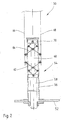
- the receptacle preferably has a wall consisting of at least two sections which are connected to one another via an energy accumulator and are movable relative to one another to a limited extent, wherein the energy accumulator is preferably designed as a compression spring.
- the receptacle has at its end facing the shaped stone advantageously converging wall sections in order to facilitate the insertion of a shaped body into a corresponding channel of the molded block.
- the Ausschubvorraum advantageously comprises a punch as a support for the molding and a preferably hydraulically or pneumatically actuated cylinder having a first piston rod and a second, connected to the gripping device piston rod, wherein the second piston rod is also preferably hydraulically or pneumatically movable.
- the first piston rod is preferably guided telescopically in the second piston rod.
- the ejection device may be designed such that it is movable in the direction of the surface normal or normal to this.
- the support surface preferably has a holding device for fixing at least one molded article to be fitted with shaped bodies.
- the receptacle may consist of thin sheet metal elements, which preferably comprise beads for reinforcement. Furthermore, the receptacle may have an outer contour that substantially coincides with the geometric shape of the channel to be filled.
- the recording is disassembled and replaceable.
- the receptacle may have on its outer surfaces sliding elements, such as plastic strips, resilient metal strips or the like.
- the receptacle may further fork-shaped at at least one end, preferably the free end be formed and have a plurality of prongs or tongues, wherein the prongs or tongues are preferably made of a resilient material, in particular of spring steel, are formed.
- the receptacle may be formed at least in two parts and the prongs or tongues of both parts offset from one another.
- the bearing surface for the shaped body is preferably movable relative to the gripping device in a plane extending parallel to a plane of the large surfaces aligned at right angles to the axial direction of the channels of the shaped body.
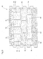
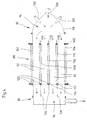
- An embodiment of a device according to the present invention for introducing pourable and / or blowable insulating particles in molded stone channels comprises at least one support surface, the support of at least to be provided with a filling and large surfaces having molded block with at least one perpendicular to the large surfaces extending channel serves, and a conveyor, which promotes pourable and / or blowable insulating particles, in particular mineral fiber with a channel flowing air stream comprises.
- the conveyor preferably has a particular bell-shaped housing, which has a supply line for the Constant pourable and / or blowable insulating particles and can be placed with the interposition of a seal on a large surface of the molded block.
- the conveyor may comprise a housing having a suction line for generating a negative pressure in the channel of the molded block for the pourable and / or blowable insulating particles to be sucked in and can be placed with the interposition of a seal on a large surface of a molded block.
- the housing can comprise an input area facing the shaped block, which has an air-permeable membrane spanning this input area, which is essentially impermeable to the pourable and / or blowable insulation particles.
- the conveying direction of the blowable insulating particles is preferably aligned substantially horizontally, wherein the channel is formed in the molded block on the output side with an air-permeable membrane.
- the membrane may be formed as a film and is preferably detachably connectable to the molded block.
- the housing preferably has a guide device, for example in the form of, at its input and / or output region facing the shaped block Baffles, up.
- the housing advantageously comprises an injection device for the addition of binding and / or impregnating agents in the flow.
- the injection device advantageously comprises at least two injection nozzles, which are arranged diametrically opposite on both sides of the supply line.
- the guide device in particular the length of the guide plates, preferably formed adjustable.
- the housing may comprise a collecting device for excess insulating particles.
- the supply line and / or the suction line preferably comprises or comprise a valve via which excess conveying air can be discharged.
- the injection device preferably has at least one storage container for binders.
- the supply line and / or the suction line are advantageously connected to a pump, in particular a vacuum pump and / or a fan.
- the present invention relates to a building, in particular a wall, consisting of at least two molded bricks according to the invention, wherein the bricks are arranged abutting with two side surfaces, wherein between the adjacently arranged molded bricks an insulating element, in particular of mineral fibers, is arranged.
- the molded blocks preferably have alternately arranged projections, in particular springs and recesses, in particular grooves, at least in the region of their abutting side surfaces.
- the insulating element is advantageously designed as a shaped body, wherein it preferably extends over approximately the entire side surface and is flush with an edge of the side surface.
- the material thickness of the insulating element is advantageously between 3 mm to 15 mm, in particular between 3 mm and 5 mm.
- the density of the insulating element is preferably in the range between 50 kg / m 3 and 120 kg / m 3 .
- the insulating element advantageously comprises at least one side an adhesion-promoting coating, so that it is firmly positioned on a molded block.
- each side face of the shaped bricks has a groove which serves to receive an insulating strip which substantially, preferably completely, fills the grooves of adjacent shaped bricks.
- the groove is preferably arranged substantially centrally in the side surface and may have different depths.
- the insulating strip advantageously has a width of the groove slightly increased material thickness, preferably between 10 mm and 70 mm, in particular between 20 mm and 40 mm.
- the groove preferably has a ratio of depth to width of 3: 1.
- the bulk density of the insulating strip is advantageously> 30 kg / m 3 .
- the insulating strip is preferably laminated on at least one large area with a heat-reflecting coating or a fiberglass mat.
- the insulating strip on a large surface may have a substantially air-impermeable coating.
- the present invention relates to a shaped brick, such as brick, especially brick, with a preferably substantially cuboid body, the two substantially parallel and spaced apart aligned large surfaces and substantially perpendicular thereto extending side surfaces and substantially parallel to the side surfaces and having substantially perpendicular to the large surfaces extending channels, wherein in at least one channel, a filling of an at least limited compressible insulating material, in particular of a mineral fiber insulation, is arranged.
- the filling has a vapor-permeable layer which is arranged together with the insulating material in the channel.
- the layer is advantageously located directly on a wall of the channel. Furthermore, a plurality of channels are preferably arranged adjacent and separated by transverse webs.
- transverse webs are preferably formed at least partially pliable.
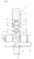
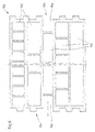
- Fig. 1 shows a partially sectioned front view of an embodiment of a first device 10 according to the present invention, which serves as a collection device for drawing a shaped body 12 into a channel 14 of a molded block 16.
- the molded block 16 is a perforated brick having channels 14, which is held by means of a gripper 18 of the device 10 to be positioned precisely such that the channels 14 of the shaped block 16 are vertical extend.
- the gripper 18 is at least horizontally, but preferably freely moved in space, so that the molded block 16 and the device 10 can be moved relative to each other so that the individual channels 14 of the molded block 16 can be filled by means of the device 10 with moldings 12.
- the molded block 16 can be optionally held by means of an alternative support, wherein the alternative support is presently formed by a perforated plate 20, the hole pattern is formed according to the channels 14 of the molded block 16.
- the device 10 is mounted on a platform 22 that is movable at least in height, but preferably freely movable in space.
- the platform 22 may for example be attached to guide rails, not shown, and is at least movable up and down by means of pneumatically or hydraulically moving piston rods or drive motors.
- the drive is preferably effected by a hydraulic drive.
- the platform 22 can also be attached to a vectorially controlled, three-dimensionally movable arm of a so-called robot in order to be able to precisely control the individual channels 14 of the molded block 16 with the aid of suitable sensors.
- the device 10 shown in FIG. 1 serves for filling a respective channel 14 of a molded block 16 with a shaped body 12.
- the device 10 can also be extended such that a plurality of channels 14 or entire rows of channels of one or more blocks 16 are simultaneously filled with corresponding moldings 12. However, this will not be discussed further below for the sake of simplicity.
- a support structure 24 is arranged, which is in the present case formed from a sleeve 26 which is connected at its upper free end fixed to a serving as a stamp plate 28 whose outer contour is smaller than that of the molded body 12 to be filled channel 14th of the molded block 16, so that the plate 28 can move through the corresponding channel 14.
- the plate 28 serves primarily to receive the shaped body 12.
- the required pressure cylinder 32 of the hydraulic drive is attached to the platform 22.
- the piston rod 30 can of course also be moved pneumatically or by means of drive motors up and down, however, as indicated previously, due to the exact positioning a hydraulic drive is preferred.
- a plurality of piston rods are movable by a single pressure cylinder, if several channels 14 of a molded block 16 are to be filled with moldings 12 at the same time.
- the piston rods can for example be attached to a common plate, which in turn is moved by a central piston rod of the impression cylinder.
- pin-shaped projections 34 are attached on both sides for coupling in each case a compression and draft-receiving linkage 36.
- the sleeve 26 is laterally open, so that the projections 34 can extend therethrough.
- corresponding, vertically extending guide slots may be provided.
- Another linkage 38 is attached to an upper guide sleeve 40, which is pushed over the sleeve 26 and guided up and down on this movable.
- the upward movement of the guide sleeve 40 is limited by the plate 28, which serves as a stop here.
- the guide sleeve 40 may alternatively be performed similar to the head 33 of the piston rod 30 within the sleeve 26.
- Both rods 36 and 38 are attached to two gripper shells 42 and 44 and give them an exact guide.
- the gripper shells 42 and 44 may for example consist of thin sheets which can accommodate the pressure forces required for the compression of the shaped body 12 without substantial deformations.
- the gripper shells 42 and 44 can be provided for stiffening with beads, which optionally form guide rails.
- plastic strips or resilient metal strips can be attached to the outside of the gripper shells 42 and 44.
- rollers or wheels can be arranged on the outside of the gripper shells 44 and 46.
- closed gripper shells 42 and 44 these can be constructed fork-shaped, wherein the prongs consist of rods or tongues made of spring steel.
- the reinforcing and guide rails as well as the tines of the forked grippers can be used in devices for the simultaneous filling of a plurality of channels 14 of a molded block 16 in each case in relation to the gripper shells 42, 44 which are moved relative to one another when opened, are arranged offset.
- the largest possible opening width can be achieved with a simultaneous filling of consecutive channels 14.
- this aspect is negligible when the device for filling only one channel 14 of a molded block 16 with a shaped body 12 is used, or if every second channel row of a molded block 16 is skipped, so that the individual gripper shells 42, 44 are not so close to each other ,
- the gripper shells 42 and 44 are angled inwardly at the lower end so that they can be easily moved into the refill channels 14 of the molded block 16.
- the device 10 is operated as follows:
- the support structure 24 For receiving the molded body 12, the support structure 24 is first brought together with the pulled-down looper shells 42 and 44 via the platform 22 in the upper position, which is shown in Fig. 1.
- the piston rod 30 moved upward, the lower linkage 36 exerts a lateral, outward pressure on the claw shells 42 and 44.
- the same is done by the upper linkage 44 after it is driven against the serving as a stop plate 28.
- the spring 46 is preferably a metal spring. Alternatively, however, an air-filled rubber cushion or a gas spring may be provided. Furthermore, it is of course possible to arrange a plurality of springs 46.
- the shaped body 12 is optionally guided or dropped by hand, by means of a corresponding task device or with the aid of a robot between the gripper shells 42 and 44 and is seated on the plate 28.
- the piston rod 30 is offset by means of the pressure cylinder 32 in a downward movement.
- the lower linkage 36 is aligned in the pulling direction.
- the platform 22 is also moved downwards, so that the angled gripper shells 42 and 44 touch the inner edges of the channels 14 of the molded block 16.
- the train of the piston rod 30 is now a sufficient counterforce on the two gripper shells 42 and 44 constructed, which now leads to the compression of the shaped body 12.
- the downward movement of the platform 22 is stopped when the plate 28 is located approximately at the level of the lower opening of the channel 14 of the molded block 16.
- the exact position is dependent on the stiffness of the insulating material of the molded body 12, but usually it is above the lower opening of the channel 14, to prevent the molded body 12 protrudes from the channel 14.
- the piston rod 30 is moved further down. Since the molded body 12 is held on the plate 28 and optionally upsetting, the gripper shells 42 and 44 are pulled past this out of the channel 14 of the molded block 16.
- the gripper shells 42 and 44 are either moved under the next channel 14 of the block 16 or the shaped block 16 is moved accordingly by means of the gripper 18. Subsequently, the support structure 24 is moved to receive a new molded body through the corresponding channel 14 of the molded block 16 upwards.
- Fig. 2 shows a partially sectioned front view of another embodiment of a device 50 according to the invention, which serves for drawing a shaped body into a channel of a molded block.
- the device 50 comprises a platform 52, which is movable by suitable means at least up and down, but preferably freely in space.
- a support structure 54 is held, which has a sleeve 56 in which two telescopically movable piston rods 58 and 60 are arranged and movable up and down.
- the actuating means for the piston rods 58 and 60 which may be, for example, pressure cylinder, are not shown in Fig. 2.
- the remaining structure of the device 50 substantially corresponds to that of the device 10 in Fig. 1, which is why will not be discussed in more detail below.
- the piston rod 60 is moved to an upper position.
- the piston rod 58 is moved upwards until the rods 62 and 64 have pushed apart the gripper shells 66 and 68.
- the piston rods 58 and 60 are pulled apart, so that the gripper shells 66 and 68 not only contactless, but even with significantly reduced thickness in the corresponding channel 14 of the molded block 16 can be fed.
- the gripper shells 66 and 68 In the lower end position of the punch-like plate 70 of the piston rod 60, the gripper shells 66 and 68 as far as it allows the channel width, moved apart and deducted from the mold body 12.
- the molded body 12 can generally protrude upwardly from the gripper shells 66 and 68 as well as laterally, so that it itself clamps during the downward movement and the frictional forces thereby developed facilitate the extraction or reduce the compression in the region of the plate 70.
- the telescopic arrangement of the piston rods 58 and 60 allows high compression of the molded body 12 with low stress on the channel inner walls, in particular the upper edges of the molded block 16 and the inevitable wear on the outer surfaces of the gripper shells 66 and 68th
- the moldings 12, which are drawn into the channels 14 of the molded blocks 16, preferably have densities in the range from 20 kg / m 3 to 120 kg / m 3 fiber mass.
- the frictional forces required for a secure clamping between at least two opposite inner walls of the holes can not be quantified directly because of the large number of types of insulating material and their inhomogeneities. However, they are achieved by a corresponding and, if necessary, easily correctable excess with respect to the compression direction.
- the oversize can be reduced with the usual contents of organic binders of 3 2% by mass with respect to the pure fiber mass with increasing bulk density. Generally standard values are approx. 1 mm to approx.
- the oversize of the moldings 12 with respect to the side surfaces lying parallel to the compression direction of the gripper shells 66, 68 depends to a great extent on their clamping effect and the compression resistance of the shaped body 12. At a low compression resistance of the molded body 12 is drawn in even at a considerable excess. If the insulation materials are less compressible, the excess is reduced to 0 or to a small undersize, if necessary, since the insulation materials compressed transversely thereto cause a slight bulging of the side walls across the thickness.
- the moldings 12 for use can be laminated on at least one surface, for example with glass fiber mats or perforated metal foils.
- Non-flammable glass fiber random webs, but also synthetic fiber random webs can serve as sliding layers. Due to their reflectivity, metal foils should reduce the radiation transmission and thus the energy transmission. Insulating moldings with radiation-reflecting films are used in particular in the room-side and thus in the heating period to be heated part of the molded block 16.
- the gripper shells 66, 68 of the collection device are arranged parallel to the longitudinal axis of the shaped stone channels. However, especially in the case of stiff rock wool insulation materials, they can also be oriented transversely thereto. Thus, the gripper shells 66, 68 can be further contracted to the respective channel center.
- the minimum channel size of the molded block 16 is technically conditioned by the size of the retraction device for the drawing of insulating moldings. With a variety of small and / or irregularly shaped holes, it is much more economical to fill them with mineral wool flakes or other blowable insulating materials.
- FIG 3 shows an example of a cross-sectional view of an embodiment of a molded block 80 according to the present invention, which is a so-called perforated brick whose channels 82 have very different geometries, but otherwise the usual outer shape.
- the moldings are formed with a density between 20 kg / m 3 and 120 kg / m 3 and can at least one side with a sliding and / or radiation-reflecting Lamination, for example, a random web, in particular a glass fiber or synthetic fiber random web or a preferably perforated metal foil be provided.
- the inner smaller channels are not filled with insulating materials. All other channels 86, in which no moldings are used, are filled with mineral wool flakes or other pourable and / or blowable insulation particles.
- the pourable and / or blowable insulation particles can be mixed with binders, in particular with inorganic water glasses, silica sol, organically modified silanes, plastic dispersions and / or thermosetting, water-soluble resins, for example phenolic resin and / or thermoplastics, the binders additionally pigments and / or or fillers.
- the pourable and / or blowable insulating particles can be produced from a mineral fiber granulate which has up to 20% by mass of binder.
- the binder in the pourable and / or blowable insulation particles is advantageously cured with microwave radiation and / or with heated air guided through the pourable and / or blowable insulation particles and / or at least one heat radiator.
- the pourable and / or blowable insulating particles can also be introduced into the channels of a given, in particular a temperature between 100 ° C and 180 ° C, preferably between 150 ° C and 180 ° C having shaped block 80.
- aerosol-like atomized oils or oil emulsions can additionally be introduced into the channels 86, in particular blown in and / or sucked in.
- the pourable and / or blowable insulation particles preferably have a density of between 45 kg / m 3 and 120 kg / m 3 in the state introduced into the molded block 80.
- An example of a corresponding blowing device is shown in FIG.
- Fig. 4 is a sectional view and shows the example of a horizontally shaped block 88, a device 90 for filling channels 92 of the block 88 with arbitrarily shaped cross-sections.
- the molded block 88 can rest on a support or be positioned by means of a gripper, which is not shown in Fig. 4.
- the device 90 comprises two independently movable heads, namely a material supply head 94 and a suction head 96.
- Both the Materialzu Fightingkopf 94 and the suction head 96 can be fixed, for example, not shown guides and means also not shown electric drives or optionally by means of pneumatically or hydraulically driven Moves piston rods and pressed from both sides according to the molded block 88.
- the heads 94 and 96 can also be moved by freely movable in space robot arms.
- the device 90 can also have a plurality of material feed heads 94 and correspondingly also suction heads 96, which are moved via a common control unit and via common guide elements.
- the supply of mineral wool flakes via the Materialzu slaughterwood 94 comprises a split sheet metal construction 98 which is pressed via a sealing ring 100 at least on the peripheral outer webs 102 and 104 of the block 88, but optionally also on the webs of a channel row or a single channel in that the gasket produced by the gasket 100 is intended to prevent the escape of conveying air and mineral wool flakes.
- the mineral wool flakes are conveyed by means of the commonly used carriers whose respective power is adapted to consumption, via one or more distribution nozzles or via several conveying lines together with corresponding connections in the direction of arrow 106 into the cavity of Materialzuseasonedkopfes 94.
- guide vanes 114, 116, 118 are arranged above the webs 108, 110, 112 of the molded block 88. These can fully reproduce the pattern with the channels to be filled.
- the height of the baffles 114, 116, 118 can be varied in order to achieve a uniform or just a selective admission of the openings of individual channel rows or individual channels 92.
- baffles 114, 116 and 118 and the congestion of mineral wool flakes before or on the webs 108, 110 and 112 is prevented, which drop after the end of the filling process and must be eliminated consuming.
- one or more bulges may be provided on the material feed head 94 in the lower part of the housing in which the excess mineral wool flakes are collected. At the beginning of the next filling process, these can then optionally be blown into the channels to be filled.
- injection nozzles 120 distributed along the circumference are provided on the material supply head 94 in the present case. If liquids are to be introduced, both injection nozzles and high-pressure nozzles with the corresponding storage containers can be installed on the conveyor.
- Suitable liquid binders are, for example, inorganic water glasses, silica sol, organically modified silanes, plastic dispersions or thermosetting, water-soluble resin mixtures.
- the components or mixtures may be added alone or together or sequentially to the mineral wool flakes or other blowable insulation materials.
- aerosol-type atomized oils or oil emulsions can be injected.
- Both the liquid inorganic and the organic binders may contain pigments and / or fillers.
- the suction head 96 of the device 90 is connected either to a pumping system, such as a vacuum pump, or to a ventilator, which produces both a sufficiently high vacuum and a sufficiently high conveying air flow. Also, the suction head 96 is sealed by means of appropriate seals 122 against the block 88 to prevent the suction of so-called false air as well as the escape of fibers safely.
- a pumping system such as a vacuum pump
- a ventilator which produces both a sufficiently high vacuum and a sufficiently high conveying air flow.
- the suction head 96 is sealed by means of appropriate seals 122 against the block 88 to prevent the suction of so-called false air as well as the escape of fibers safely.
- a screen 124 which intercepts the mineral wool flakes or non-fibrous particles contained therein. By occupying with the mineral wool flakes, a filter quickly builds up on the screen 124, which itself is highly effective.
- the suction head 96 is subdivided by means of baffles 126 or by means of fixtures adapted to the web widths of the molded block 88. In this way, similar to the baffles 114, 116 and 118, a uniform application or filling of the channels 92 of the molded block 88 is effected.
- the screen 124 can be set back so far along the baffles 126 in the suction 96, that after each filling always enough residual material remains, so that from the outset, a sufficiently high filter resistance is present.
- the vacuum and / or the exhaust air flow can be varied.
- the individual connection of individual channels 92 or rows of channels to the exhaust system, the filling of different channels 92, both in terms of time and the bulk density of the mineral wool flakes are made uniform or similar.
- the bulk density of the injected or sucked mineral wool flakes varies depending on the original floc size and the channel geometries between about 45 kg / m 3 to 120 kg / m 3 .
- the highly compressed mineral wool flakes after lifting the heads 94 and 96 is still a slight expansion, so that the insulating material from the channels 92 of the molded block 88 can swell out. By slightly brushing over the supernatant material can be finally removed.
- the mineral wool flakes can be added to binders or be subsequently sprayed onto the open end faces of the molded block 88.
- binders either dry atmospherically or are solidified, especially in the near-surface zones, by virtue of the fact that the shaped brick 88 is pushed past area-effect radiant heaters.
- other drying methods are conceivable.
- the additional impregnation with oil should increase the often required water repellency of the mineral wool flakes or bring after the addition of binders to the old state.
- blowable insulation particles may be introduced into the channels 92 of the molding block 88, such as cellulose fibers, expanded glass, pumice, polystyrene beads or the like. These blowable insulating particles can also be impregnated with binders and connected to one another and to the inner walls of the channels 92 of the molded block 88. In most cases, even the form-fitting bond with the inner walls of the holes is sufficient to prevent falling not too heavy masses.
- FIG. 5 shows a cross-sectional view of another embodiment of a molded block 130 according to the invention.
- the channels 132 of the molded block 130 are filled with insulating material by first blowing in mineral wool flakes which form a plug 134 approximately 20 mm to 50 mm high, which is bound by a binder is fixed. Subsequently, unbound loose particles 136 are filled, the final conclusion in turn a plug 138 bound from Mineral wool flakes forms, which is shown on the left side in Fig. 5.
- the plugs closing off a channel 132 may also be formed, for example, from shaped articles, such as rockwool moldings with densities> 40 kg / m 3 , as shown in FIG. 5 by the plugs designated by the reference numbers 140 and 142.
- FIG. 6 shows a further embodiment of a molded block 150 according to the invention, which has any channel pattern conceived taking into consideration aspects of heat and / or sound insulation.
- the channels 152 of the molded block 150 may optionally be filled with insulating materials.
- the side surfaces 154 of the molded block 150 are formed toothed, whereby an accurate positioning of adjacent blocks 150 is ensured relative to each other.
- Grooves 156 extending in each case over the height of the molded block 150 are formed in the side surfaces 154, into which, preferably after the setting of the molded block 150, an insulating molded article (not shown) with, for example, a rectangular cross section can be inserted.
- the insulating molded body can already be clamped at the factory, but there is a risk that it will be damaged in the handling of the block 150 and then no longer fits into the corresponding groove 156 of the adjacent block 150 to be arranged.
- This insulating molded body is intended to reduce heat as well as shadow bridge effect of the butt joints.
- the grooves 156 can each be arranged in the middle of the toothed side surface 154 of the molded block 150, to allow a symmetrical toothing. However, it is also possible that the grooves 154 are arranged off-center. The depth of the grooves 156 may be equal or different on both sides.
- the thickness of the preferably made of mineral wool insulating molding is about 10 mm to about 70 mm, preferably about 20 mm to 40 mm.
- the cross-section is usually rectangular, the width-to-thickness ratio mostly> 3: 1. In order to achieve sufficient rigidity, the bulk density should exceed> 30 kg / m 3 .
- the insulating molded body can be laminated on one or both sides with heat-reflecting layers or fiberglass nonwovens. Furthermore, it may have an air-inhibiting coating alone or in addition to the aforementioned laminations. This air-inhibiting coating is preferably directed outwards.
- FIG. 7 shows a cross-sectional view of another embodiment of two adjacently arranged molded bricks 160 according to the present invention.
- the molded blocks 160 likewise have moldings 160 made of insulating material Channels 162 and provided with a toothing end faces 166. Between the toothed end faces 166 of the adjacently arranged molded blocks 160, a shaped body, preferably formed of rock wool, is provided which has a form corresponding to the serrations of the end faces 166 of the adjacently arranged shaped blocks 160.
- the height of the molded body 168 corresponds to the height of the molded blocks 160.
- the thickness of the molded body 168 is about 3 mm to 15 mm, preferably about 3 mm to 5 mm.
- the apparent density is in a range of preferably between 50 kg / m 3 and 120 kg / m 3 .
- the mold body 168 may be flush with the side surfaces of the adjacently located mold bricks 160, see reference numeral 170. This embodiment is appropriate when the outer surface of the outer wall made of these mold bricks 160 is covered, for example, with another insulating layer or only with a ventilated clothing.
- the molded body 168 may alternatively spring back slightly on the usually plastered inner wall surface, see reference numeral 172.
- One or both side edges of the molding 168 may be provided with adhesion promoting primers.
- adhesion-promoting primers or layers By means of these adhesion-promoting primers or layers, a non-positive bond with the plaster layers is to be achieved.
- Fig. 8 shows a cross-sectional view of another embodiment of a molded block 180 according to the invention with a two-part construction.
- the first part 182 is formed with a high bulk density and smaller channels 184, while the second part 186, which is preferably directed outwardly, has a lower bulk density and correspondingly a lower compressive strength, but a higher thermal resistance.
- the insulating shaped body 188 and insulating flakes 190 are preferably introduced into the corresponding channels of the second part 186.
- the two parts 182 and 186 of the molded block 190 are prepared as usual, each in a separate extruder and joined together by applying a slip on the adhesive surfaces, dried and fired.
- flat grooves may be formed in the wall of the rear part, in which the webs of the part to be bonded are introduced, which is not shown here.
- both parts 182 and 186 of the molded block 180 can be glued to high-strength synthetic resins.
- the minimum width of the rear part 182 of the molded block 180 is preferably 3 17.5 cm.
- the bonding surfaces are treated with suitable primers, that is, sufficiently deep-primed. This pretreatment is known in principle. If multi-component resins with sufficient reaction rate and heat release are used, a post-curing is unnecessary. Prophylactically, however, the bonding surfaces are heated and, if necessary, also after the application of the adhesive aftertreated, for example, to obtain a consistently solid compound at lower temperatures in the production halls.
- Fig. 9 shows a cross-sectional view of another embodiment of a molded block 192 according to the invention, the channels 194 are at least partially filled with segments 196 and 198 of mineral wool pipe shells.
- pipe shells are preferred with a sufficiently high rigidity in the axial direction.
- the segments 196 have the shape of the channels 194 corresponding to beveled longitudinal side surfaces.
- the tubing segments can be stretched along the tendon and thus easily inserted into the channels 194.
- the small thicknesses of the side surfaces do not lead to high frictional forces and excessive abrasion, so that a tight fit is ensured.
- the tubing segments 196, 198 may be divided in height and inserted into the channels 194 from both sides.
- the pipe shell segments 194 and 196 serve primarily the airborne sound damping. You should therefore be placed at any angle to the outer surfaces, so that they point in different directions.
- Tubular shell segments are particularly suitable for filling round or elliptical holes. They may be laminated with perforated metal foils and / or with air-permeable nonwovens or coated with sealing paints, plasters or the like.
Abstract
Description
Die Erfindung betrifft ein Verfahren zur Herstellung eines Formsteins, beispielsweise eines Mauersteins, insbesondere eines Ziegels mit einem vorzugsweise im wesentlichen quaderförmigen Körper, der zwei im wesentlichen parallel und im Abstand zueinander ausgerichteten großen Oberflächen und im wesentlichen hierzu rechtwinklig verlaufende Seitenflächen sowie im wesentlichen parallel zu den Seitenflächen und im wesentlichen rechtwinklig zu den großen Oberflächen verlaufende Kanäle aufweist, die zumindest teilweise eine Füllung aus einem zumindest begrenzt kompressiblen Dämmstoffmaterial, insbesondere aus einem Mineralfaserdämmstoff eingebracht wird.The invention relates to a method for producing a molded block, for example a brick, in particular a brick with a preferably substantially cuboid body, the two substantially parallel and spaced apart aligned large surfaces and substantially perpendicular thereto extending side surfaces and substantially parallel to the Side surfaces and substantially perpendicular to the large surfaces extending channels, which is at least partially a filling of an at least limited compressible insulating material, in particular of a mineral fiber insulation is introduced.
Die Erfindung betrifft ferner eine Vorrichtung zur Durchführung des Verfahrens sowie einen Formstein, beispielsweise Mauerstein, insbesondere Ziegel mit einem vorzugsweise im wesentlichen quaderförmigen Körper, der zwei im wesentlichen parallel und im Abstand zueinander ausgerichtete große Oberflächen und im wesentlichen hierzu rechtwinklig verlaufende Seitenflächen sowie im wesentlichen parallel zu den Seitenflächen und somit im wesentlichen rechtwinklig zu den großen Oberflächen verlaufende Kanäle aufweist, wobei zumindest einem Kanal eine Füllung aus einem zumindest begrenzt kompressiblen Dämmstoffmaterial, insbesondere aus einem Mineralfaserdämmstoff angeordnet ist.The invention further relates to a device for carrying out the method and a molded block, such as brick, in particular brick with a preferably substantially cuboid body, the two substantially parallel and spaced apart aligned large surfaces and substantially perpendicular thereto extending side surfaces and substantially parallel to the side surfaces and thus has substantially perpendicular to the large surfaces extending channels, wherein at least one channel is a filling of an at least limited compressible insulating material, in particular of a mineral fiber insulating material is arranged.
Schließlich betrifft die Erfindung ein Bauwerk, insbesondere eine Mauer, bestehend aus zumindest zwei Formsteinen, wobei die Formsteine mit zwei Seitenflächen aneinander stoßend angeordnet sind.Finally, the invention relates to a building, in particular a wall, consisting of at least two molded bricks, wherein the bricks are arranged with two side surfaces abutting each other.
Gebäude weisen Außen- und innere Trennwände auf. Diese Wände trennen beheizte von nicht beheizten Räumen. In der Regel treten Transmissionswärmeverluste über die Außenwände auf, die als multifunktionelle Bauteile einen wesentlichen Bestandteil der Tragkonstruktion darstellen und daher eine ausreichende Druckfestigkeit aufweisen müssen. Da Außenwände das Gebäudeinnere von der äußeren Umgebung und damit von den Auswirkungen der Atmosphärilien trennen und Transmissionswärmeverluste begrenzt werden müssen, ist es üblich, die Außenwände mit einer Wärmedämmung auszubilden. Ferner sollen Außenwände eine möglichst hohe Schalldämmung bewirken, um sowohl Außenlärm gegenüber den Innenräumen abzumindern als auch Schallemissionen nach außen zu verringern.Buildings have outer and inner partitions. These walls separate heated from unheated rooms. As a rule, transmission heat losses occur via the outer walls, which, as multifunctional components, represent an essential component of the supporting structure and therefore must have sufficient compressive strength. Since exterior walls must separate the interior of the building from the outside environment and thus the effects of the atmosphere and transmission heat losses must be limited, it is common practice to form the exterior walls with thermal insulation. Furthermore, exterior walls should bring about the highest possible sound insulation, in order to both reduce external noise compared to the interior and to reduce noise emissions to the outside.
Es wird zwischen Luftschalldämmung und Körperschalldämmung unterschieden. Luftschall wird beispielsweise durch das Sprechen, Körperschall durch die direkte Anregung der Wand, z. B. durch Betätigung ein- oder angebauter Armaturen, Klopfen oder dergleichen erzeugt. Als Schalldämmmaß wird das logarithmische Verhältnis der auf eine Wand auftreffenden Schallenergie zu der durchgelassenen Energie bezeichnet. Das Schalldämmmaß steigt bei einschaligen homogenen Wänden mit dem Flächengewicht, der Zusammenhang wird als Berg'sches Gesetz bezeichnet. Bei porigen oder vielkammerigen Wänden sind die erreichbaren Schalldämmungsmaße von vielen Faktoren abhängig. Generell sollen in diesen Wänden vorhandene Hohlräume klein sein, damit deren Begrenzungsflächen nicht bereits durch geringe Schallenergie zum Schwingen angeregt werden. Wenn die Bauteile der Wand in Resonanzschwingungen geraten, führt das regelmäßig in einem bestimmten Frequenzbereich zu einer deutlichen Abminderung des Schalldämmmaßes.A distinction is made between airborne sound insulation and structure-borne sound insulation. Airborne sound is, for example, by speaking, structure-borne noise by the direct excitation of the wall, z. B. generated by actuation on or attached fittings, knock or the like. The sound reduction factor is the logarithmic ratio of the sound energy incident on a wall to the transmitted energy. The sound reduction coefficient increases with single-shell homogeneous walls with the basis weight, the connection is called Berg'sches law. For porous or multi-walled walls, the achievable sound insulation dimensions depend on many factors. In general, cavities present in these walls should be small so that their boundary surfaces are not already excited by small sound energy to vibrate. If the components of the wall get into resonant vibrations, this regularly leads to a significant reduction of the sound insulation value in a certain frequency range.
Als weitere wesentliche Anforderung müssen Außenwände einen Schutz gegen Brandangriffe von außen und gegen eine Brandweiterleitung nach außen bilden.As a further essential requirement, external walls must provide protection against external fire attacks and against fire propagation to the outside.
Wände werden beispielsweise aus Formsteinen, beispielsweise aus Ziegeln hergestellt, die aus Ton, Lehm oder einer tonigen Masse bestehen und seit langer Zeit bewährte Baustoffe für Außenwände darstellen. Es werden luftgetrocknete Ziegel und gebrannte Ziegel unterschieden.Walls are made, for example, from shaped bricks, for example made of bricks, which consist of clay, loam or a clayey mass and have long been proven building materials for exterior walls. A distinction is made between air-dried bricks and fired bricks.
Die Formgebung der für die Ziegelherstellung verwendeten plastischen und somit bildsamen tonmineralhaltigen Massen erfolgt mit Hilfe von kontinuierlich arbeitenden Strangpressen. Ein endloser Massenstrom wird unter Berücksichtigung von Trocken- und Brennschwindung entsprechend der Höhe des gebrannten Ziegels als Formlinge von der Masse mit Hilfe eines dünnen Drahtes abgelängt. Nach dem Trocknen der Formlinge werden diese gebrannt. Durch das Erhitzen wird den Tonmineralien das chemisch gebundene Wasser ausgetrieben, so daß feinporöse Ziegel entstehen, die druckfest und in Wasser unlöslich sind.The shaping of the plastic and thus plastic clay-containing masses used for the brick production takes place with the help of continuous extruders. An endless mass flow, taking into account drying and burning shrinkage, corresponding to the height of the fired brick as moldings cut to length from the mass with the help of a thin wire. After drying the moldings they are fired. By heating the clay minerals, the chemically bound water is expelled, so that fine-porous brick arise, which are pressure-resistant and insoluble in water.
Die Ziegel bestehen aus einem gebrannten Scherben, der porös und kapillaraktiv ist und eine Wasserdampf-Diffusionswiderstandszahl µ von ca. 10 aufweist, die im feuchten Zustand auf µ = 5 abfällt. Es wird eine Porengröße bzw. Porengrößenverteilung angestrebt, die den Scherben fortbeständig macht. In die Ziegel bzw. daraus hergestellte Wände eindringende Feuchte kann sich gut in diesen verteilen und leicht abdiffundieren, wobei der gebrannte Scherben weitgehend unverändert bleibt. Genormte Ziegel weisen bei Rohdichten zwischen 1.200 und 2.000 kg/m3 hohe Druckbeständigkeiten, aber mit 0,50 bis 0,81 w/m o K auch hohe Wärmeleitfähigkeiten ? auf. Der Wärmedurchlaßwiderstand einer beidseitig unverputzten 24 cm dicken Wand aus Ziegeln mit einer Rohdichte ? von 1.600 kg/m3, die in einem üblichen Zement-Kalk-Mörtel verlegt sind, beträgt nur ca. 0,35 m2 o K/W. Diese Wand weist einen Wärmedurchgangskoeffizienten U von ca. 2 W/m2 K auf. Wegen des hohen Flächengewichts ist das Schalldämmmaß allerdings hoch.The bricks consist of a burned body, which is porous and capillary active and has a water vapor diffusion resistance coefficient μ of about 10, which drops to μ = 5 in the wet state. It is a pore size or pore size distribution sought, which makes the broken pieces persistant. Moisture penetrating into the bricks or walls produced therefrom can be well distributed in these and easily diffused out, whereby the fired body remains largely unchanged. Standardized bricks have high compressive strengths at densities between 1,200 and 2,000 kg / m3, but with 0.50 to 0.81 w / m o K also high thermal conductivities? on. The thermal resistance of a brick wall of bricks with a gross density of 24 cm thick which was not plastered on both sides? of 1,600 kg / m3 laid in a standard cement-lime mortar is only about 0,35 m2 o K / W. This wall has a heat transfer coefficient U of about 2 W / m2 K. However, because of the high basis weight, the sound reduction index is high.
Um den Wärmedurchgangskoeffizienten U von derartigen Außenwänden auf einen als angemessen angesehenen Wert von = 0,3 W/m2 o K zu reduzieren, wird eine aus diesen Ziegeln hergestellte Wand an ihrer Außenseite mit Wärmedämmstoffen verkleidet. Beispielsweise können die Wärmedämmstoffe als hinterlüftete Bekleidungen oder mit direkt auf den Dämmschichten aufgetragenen Putzschichten in Form sogenannter Wärmedämm-Verbundsysteme ausgebildet sein.In order to reduce the heat transfer coefficient U of such outer walls to a value of = 0.3 W / m 2 o K considered appropriate, a wall made of these bricks is clad on its outside with thermal insulation materials. For example, the thermal insulation materials can be designed as ventilated claddings or with plaster layers applied directly to the insulating layers in the form of so-called composite thermal insulation systems.
Bei Neubauten werden zumeist schlanke Wandschalen aus hochfesten und deshalb hoch wärmeleitenden Baustoffen wie Beton, Kalksand-Vollsteinen, Voll- oder Hochlochziegeln erstellt und auf die geschilderte Weise gedämmt. Bei diesen Konstruktionen können die Anforderungen an den Wärme-, Schall- und Brandschutz mit verschiedenartigen optischen Anmutungen kombiniert werden. Die massiven Wandschalen sind zudem gute Wärmespeicher und tragen zur Vergleichmäßigung des Innenraumklimas bei. In den Wandschalen können von den Nutzern der Gebäude Befestigungsmittel, beispielsweise mit Hilfe von Dübeln, leicht verankert werden.In new buildings mostly slender wall shells made of high-strength and therefore highly thermally conductive building materials such as concrete, sand-lime bricks, solid or perforated bricks are created and insulated in the manner described. In these constructions, the requirements for heat, sound and fire protection can be combined with various optical impressions. The solid wall shells are also good heat storage and contribute to the homogenization of the indoor climate. In the wall shells fastening means, for example by means of dowels, can be easily anchored by the users of the building.
Eine Reduzierung des Gewichts und damit auch des spezifischen Energieeinsatzes bei der Herstellung der Ziegel wird durch die Ausbildung von Hochlöchern in dem Formstein erreicht. Die Hochlöcher sind rechtwinklig zu Lagerflächen angeordnet. Als Lagerfläche ist das Produkt aus Länge x Breite des Formkörpers definiert. Neben Formsteinen in Form von Ziegeln trifft dies auch auf diskontinuierlich in Formen gepreßten Kalksand-, Beton- oder Hüttensteinen zu. In Bezug auf die Größe des Wärmedurchgangskoeffizienten wirken sich diese Hochlöcher durch ihren geringen Volumenanteil und die hohe Wärmeleitfähigkeit des Formsteins nur in geringem Maße aus. Bei als Leichthochlochziegel bezeichneten Formsteinen wird die auf = 1.000 kg/m3 begrenzte Rohdichte zum einen durch eine verringerte Rohdichte des strukturbildenden keramischen Scherbens und zum anderen durch einen hohen Anteil Hochlöcher von über 50 % in Bezug auf die jeweilige Lagerfläche erreicht. Die Reduktion der Rohdichte des keramischen Scherbens erfolgt durch ein Ausbrennen von darin verteilt angeordneten feinen Partikeln.A reduction of the weight and thus also of the specific use of energy in the production of bricks is achieved by the formation of high holes in the Form stone achieved. The high holes are arranged at right angles to bearing surfaces. As bearing surface, the product of length x width of the molding is defined. In addition to shaped bricks in the form of bricks, this also applies to lime sand, concrete or slag bricks which are pressed discontinuously into molds. In terms of the size of the heat transfer coefficient, these high holes affect only a small extent due to their low volume fraction and the high thermal conductivity of the molded block. For shaped bricks called light hollow bricks, the density limited to = 1.000 kg / m3 is achieved on the one hand by a reduced bulk density of the structure-forming ceramic shards and on the other hand by a high proportion of high holes of more than 50% with respect to the respective bearing surface. The reduction of the bulk density of the ceramic cullet is carried out by burning out arranged therein fine particles.
Großformatige und/oder schwere Formsteine weisen ferner Grifflöcher auf, welche die Handhabung insbesondere des Setzten der Formsteine erleichtern.Large-sized and / or heavy molded blocks also have grip holes, which facilitate the handling, in particular of the setting of the molded blocks.
Hochziegel, wie auch Leichthochlochziegel weisen bestimmte Lochbilder auf, die als Lochung A, B oder C bezeichnet werden. Der Lochanteil darf bei Ziegeln mit Grifflöchern 55 % betragen. Die Durchmesser der kreisförmigen, ellipsenförmigen oder rhombischen Löcher sind festgelegt. Leichthochlochziegel sind Ziegel mit einer Lochung B und haben eine Höhe von 238 mm, welche zusätzliche Anforderungen u. a. hinsichtlich der Lochreihenzahl erfüllen müssen.Hochziegel, as well as light hollow bricks have certain hole patterns, which are referred to as holes A, B or C. The hole percentage may be 55% for bricks with handle holes. The diameters of the circular, elliptical or rhombic holes are fixed. Lightweight bricks are bricks with a hole B and have a height of 238 mm, which additional requirements u. a. have to meet in terms of the number of holes.
Zwischen den in Lochreihen angeordneten Löchern sind Stege angeordnet, die eine bestimmte Stegdicke aufweisen. Die Summe der Stegdicken rechtwinklig zur Wanddicke bzw. bezogen auf die Länge des Ziegels muß = 250 mm/m sein. Die Stege können versetzt zueinander angeordnet sein.Between the holes arranged in rows of webs webs are arranged, which have a certain web thickness. The sum of the web thicknesses at right angles to the wall thickness or relative to the length of the brick must be = 250 mm / m. The webs can be arranged offset from one another.
Mit Rohdichten = 1.000 kg/m3 werden möglichst großformatige filigrane keramische Formsteine hergestellt, deren niedrigste Wärmeleitfähigkeiten ca. 0,24 W/m K betragen. Diese Formsteine werden mit Leichtmörteln LM 21 (?10,tr = 0,18 W/m K) oder LM 36 (?10,tr = 0,27 W/m K) im Verband verlegt. Beim Auftrag des Leichtmörtels auf die obere Lagerfläche des Formsteins kann natürlich Leichtmörtel in die Löcher hineinfallen oder sich in die Löcher erstrecken. Die Formsteine werden mit ihren Stirnflächen dicht aneinanderliegend angeordnet, so daß zwischen den Formsteinen bestehende Stoßfugen unvermörtelt bleiben. Das ist möglich, wenn beide Stirnflächen der Formsteine Zähne und Ausnehmungen aufweisen, die so angeordnet sind, daß diese beim Zusammensetzen der Formsteine ineinander greifen und somit verspringende Stoßfugen bilden. Diese Zähne und Ausnehmungen werden nicht nachbearbeitet, so daß die Stoßfugen wegen der unvermeidbaren Maßtoleranzen nicht geschlossen, sondern zumindest partiell offen sind. Hieraus ergeben sich Wärmebrücken. Wesentlich nachteiliger ist aber die Wirkung der teilweise offenen Stoßfugen hinsichtlich einer Schalldurchleitung. Relative Bewegungen der Formsteine im Bereich der offenen Stoßfugen können ferner zu Rissen in einer einseitig oder beidseitig aufgetragenen Putzschichten führen.Gross densities = 1,000 kg / m3 are used to produce as large as possible filigree ceramic shaped bricks, whose lowest thermal conductivities are approx. 0.24 W / m K. These bricks are laid with lightweight mortar LM 21 (? 10, tr = 0.18 W / m K) or LM 36 (? 10, tr = 0.27 W / m K) in association. When applying the light mortar on the upper bearing surface of the block, of course, light mortar can fall into the holes or extend into the holes. The stones are arranged close to each other with their faces, so that existing joints between the blocks remain ungrounded. This is possible if both faces of the blocks have teeth and recesses which are arranged so that they engage in the assembly of the stones together and thus form verspringende butt joints. These teeth and recesses are not reworked, so that the butt joints are not closed because of the unavoidable dimensional tolerances, but at least partially open. This results in thermal bridges. Significantly disadvantageous, however, is the effect of the partially open butt joints in terms of sound transmission. Relative movements of the shaped blocks in the area of the open butt joints can also lead to cracks in a plaster layer applied on one or both sides.
Zur Verbindung voranstehend beschriebener Formsteine, insbesondere Ziegel, werden Dünnbettmörtel verwendet, bei denen es sich um Mörtel mit Zement und Sand bis 1 mm Korngröße sowie Zusatzmitteln und Zusatzstoffen handelt, die u. a. das Wasserrückhaltevermögen des Dünnbettmörtels erhöhen, damit dem Zement nicht das für die Hydratation erforderliche Wasser durch die Umgebung entzogen wird. Für die Verwendung von Dünnbettmörteln müssen die Lagerflächen der Ziegel glatt und plan parallel zueinander verlaufend geschliffen werden, so daß Dickentoleranzen auf < 1 mm reduziert werden und gleichzeitig entsprechend ebene Lagerflächen entstehen. Diese handelsüblich Planziegel genannten Formsteine können mit der unteren Lagerfläche und einer Stirnfläche in die Dünnbettmörtelschicht getaucht werden und nehmen dabei in Abhängigkeit von der Zeit eine bestimmte Menge Dünnbettmörtel auf, der wegen seiner begrenzten inneren Kohäsion nur in einer dünnen Schicht anhaftet. Die Ziegel werden anschließend im Verband auf- und nebeneinander gesetzt. Der Abstand benachbart angeordneter Ziegel und damit die Fugendicke bleibt bei dieser Verarbeitung auf 1 bis 3 mm beschränkt, so daß der Mörtel nur an den Stegen der Ziegel haftet. Die Wärmebrückenwirkung der Dünnbettmörtelschicht ist trotz der relativ hohen Wärmeleitfähigkeit des Dünnbettmörtels gering. Der Dünnbettmörtel kann auch durch Aufziehen mit Hilfe einer Vorrichtung auf die oberen Lagerflächen einer Reihe nebeneinander angeordneter Ziegel appliziert werden.For connecting above-described molded bricks, especially bricks, thin-bed mortars are used, which are mortars with cement and sand to 1 mm grain size and additives and additives that u. a. Increase the water retention capacity of the thin bed mortar so that the cement does not deprive the water required for hydration from the environment. For the use of thin-bed mortars, the bearing surfaces of the bricks must be smooth and flat plan running parallel to each other, so that thickness tolerances are reduced to <1 mm and at the same time correspondingly flat bearing surfaces arise. These commercially available planographic blocks called molding blocks can be immersed in the thin bed mortar layer with the lower bearing surface and an end face and take on a certain amount of thin-bed mortar depending on the time, which adheres only in a thin layer due to its limited internal cohesion. The bricks are then placed up and down in a bandage. The distance adjacent tile arranged and thus the joint thickness remains limited in this processing to 1 to 3 mm, so that the mortar adheres only to the webs of the tile. The thermal bridge effect of the thin-bed mortar layer is low despite the relatively high thermal conductivity of the thin-bed mortar. The thin-bed mortar can also be applied by mounting with the aid of a device on the upper bearing surfaces of a series of juxtaposed bricks.
Die Hochlöcher in den Ziegeln werden durch das Abdecken mit einer Mörtelschicht zu abgeschlossenen Kammern.The high holes in the bricks become closed chambers by covering with a layer of mortar.
Die dünnen, porosierten Stege der Leichthochlochziegel lassen sich durch Schallwellen anregen, wobei die Löcher bzw. die im Mauerwerk geschlossenen Kammern der Ziegel den Charakter von Resonanzkörpern annehmen. Aus brennwie auch aus verarbeitungstechnischen Gründen sowie wegen der erforderlichen Festigkeit der aus den Ziegeln zu erstellenden Wände sind die Leichthochlochziegel in ihren horizontalen Querschnitten symmetrisch ausgebildet. Schalltechnisch nachteilig wirken sich ferner unvermörtelte und deshalb luftdurchlässige Stoßfugen aus. Dies trifft auch zu, wenn beide Wandflächen mit Putzschichten abgedeckt sind.The thin, porosierte webs of the lightly hollow bricks can be stimulated by sound waves, whereby the holes or the closed in the brickwork chambers of the bricks assume the character of resonance bodies. For burning as well as processing-technical reasons and because of the required strength of the walls to be created from the bricks, the lightweight hollow bricks are formed symmetrically in their horizontal cross sections. Soundproof adversely affect also ungrounded and therefore air-permeable butt joints. This is also true if both wall surfaces are covered with plaster layers.
Die Schalldämmmaße von Wänden, die aus Leichthochlochziegeln bestehen, sind häufig zu niedrig. In Bezug auf eine Schalllängsleitung können sich Unterbrechungen an den Stoßfugen auch wiederum günstig auswirken.The sound insulation of walls made of light heavy bricks is often too low. With regard to a longitudinal sound pipe, interruptions to the butt joints can in turn also have a favorable effect.
Einen diese Nachteile vermeidende Hochlochziegel mit einer großen Anzahl von Kanälen beschreibt die
Bei einem Lochanteil in Bezug auf die Lagerfläche von > 50 % soll die Rohdichte des Hochlochziegels > 600 kg/m3 betragen. In mindestens eine der größeren Lochkammern soll ein Formkörper aus Dämmmaterial angeordnet werden, der geringfügig kleiner als die Abmessungen des ihn aufnehmenden Loches ist. Das erleichtert naturgemäß das Hereinschieben von harten, inkompressiblen oder selbst wenig steifen Dämmstoffen. Um ein Herausfallen des Formkörpers bei der Handhabung oder beim Transport des Hochlochziegels zu vermeiden, weisen die Löcher scharfe Kanten, Spitzen, vorzugsweise dreieckförmige Leisten oder hakenförmige Vorsprünge auf. Diese Vorsprünge dienen als Haltevorrichtungen und sind vorzugsweise einander gegenüberliegend angeordnet, um überhaupt wirksam werden zu können. Weiterhin weist eine mit Leichtmörtel aus den vorbekannten Hochlochziegeln aufgemauerte Wand von 36,5 cm Dicke eine nur unzureichende Wärmeleitfähigkeit auf.With a hole proportion in relation to the bearing surface of> 50%, the bulk density of the perforated brick should be> 600 kg / m3. In at least one of the larger perforated chambers, a molded body of insulating material is to be arranged, which is slightly smaller than the dimensions of the hole receiving it. This naturally facilitates the pushing in of hard, incompressible or even less stiff insulating materials. In order to avoid falling out of the molding during handling or during transport of the perforated brick, the holes have sharp edges, tips, preferably triangular strips or hook-shaped projections. These projections serve as holding devices and are preferably arranged opposite one another in order to be effective at all. Furthermore, a light mortar from the previously known hollow bricks brick wall of 36.5 cm thickness only insufficient thermal conductivity.
Der Hochlochziegel wird im Herstellerwerk mit den Formkörper bestückt, wobei als Dämmstoff Mineralwolle oder Kunststoff, beispielsweise Polystyrol verwendet wird. Die Formkörper werden mit den der zur Aufnahme bestimmten Löchern entsprechender Abmessung ausgebildet und können etwas kleiner als der Querschnitt der Löcher ausgeführt sein, um ein leichteres Einführen zu ermöglichen, wobei der Eingriff der auskragenden Kanten der Ausformungen in die eingesteckten Formkörper aber noch gewährleistet ist. Beim Einsteckvorgang wird der Formkörper mit Druck in Richtung seiner Längsachse in das Loch geschoben.The perforated brick is fitted in the factory with the moldings, being used as insulation mineral wool or plastic, such as polystyrene. The moldings are formed with the holes intended for receiving corresponding dimension and may be made slightly smaller than the cross section of the holes to allow easier insertion, but the engagement of the projecting edges of the moldings is still guaranteed in the inserted moldings. When inserting the molded body is pushed with pressure in the direction of its longitudinal axis in the hole.
Ferner sind aus der
Die Formgebung der Hohlräume und der Rauhigkeit der die Kanäle begrenzenden Stege verhindern das Einbringen von Formkörpern bzw. machen es vollkommen unwirtschaftlich.The shape of the cavities and the roughness of the channels delimiting webs prevent the introduction of moldings or make it completely uneconomical.
Aus der
Aus dem voranstehend dargestellten Stand der Technik ist es bereits bekannt, Dämmstoffe aus Mineralfasern in die Kanäle eines Ziegels einzubringen. Diese Dämmstoffe bestehen aus glasig erstarrten Mineralfasern mit mittleren Durchmessern von ca. 2 - 6 µm. Die Mineralfasern sind biolöslich. Handelsüblich werden Glaswolle- und Steinwolle-Dämmstoffe unterschieden. Aufgrund der hohen Gehalte von Alkalien und Boroxiden schmelzen die Glaswolle-Dämmstoffe bereits bei knapp über 650°C, während Steinwolle-Dämmstoffe einen Schmelzpunkt > 1.000°C nach DIN 4102 Teil 17 aufweisen. Die Dämmstoffe werden gewöhnlich mit Mischungen aus duroplastisch aushärtenden Phenol- und Formaldehyd-Harnstoffharzen verbunden. Durch Zusätze von Mineralölen, Silikonölen und -harzen sind die aus den Mineralfasern hergestellten Dämmstoffe nahezu vollständig wasserabweisend ausgerüstet.From the prior art described above, it is already known to introduce insulating materials made of mineral fibers in the channels of a brick. These insulating materials consist of vitreous solidified mineral fibers with average diameters of approx. 2 - 6 μm. The mineral fibers are biosoluble. Commercially available glass wool and rock wool insulation materials are distinguished. Because of the high Salts of alkalis and boron oxides melt the glass wool insulating materials at just over 650 ° C, while rock wool insulation materials have a melting point> 1,000 ° C according to DIN 4102 Part 17. The insulating materials are usually combined with mixtures of thermosetting phenolic and formaldehyde-urea resins. By adding mineral oils, silicone oils and resins, the insulating materials made from the mineral fibers are almost completely water-repellent.
Zur Herstellung von Glaswolle-Dämmstoffen werden Schmelzen verwendet, die vollständig in Mineralfasern umgewandelt werden können. Die mit Binde- und Zusatzmitteln imprägnierten Mineralfasern werden unterhalb eines Fallschachts als Mineralfaserbahn auf einem langsam laufenden luftdurchlässigen Förderband ausgesammelt. Dabei liegen die in sich glatten Mineralfasern flach, wenn auch regellos gerichtet übereinander. Die aus den Mineralfasern gebildete Faserbahn weist große Oberflächen und Seitenflächen auf und wird leicht in vertikaler Richtung gestaucht, wobei ihre Struktur anschließend durch ein Aushärten der Bindemittel fixiert wird.For the production of glass wool insulating materials melts are used, which can be completely converted into mineral fibers. The impregnated with binders and additives mineral fibers are collected below a chute as a mineral fiber web on a slow-moving air-permeable conveyor belt. The smooth mineral fibers lie flat, albeit randomly aligned. The fibrous web formed from the mineral fibers has large surfaces and side surfaces and is easily compressed in the vertical direction, and its structure is then fixed by curing the binders.
Durch die flache Lagerung der Mineralfasern rechtwinklig zu den großen Oberflächen ist der Wärmestrom in Richtung der großen Oberfläche deutlich geringer als in Richtung der Seitenflächen, also parallel zu den Mineralfasern. Die Wärmeleitfähigkeiten können sich um bis zu ca. 0,003 W/m K unterscheiden, so daß die Dämmstoffe bei normaler Anordnung mit einer Ausrichtung der großen Oberflächen quer zum Hauptwärmestrom regelmäßig in die Wärmeleitfähigkeitsgruppe 035 nach DIN 4108 und mit der Anordnung der Mineralfasern parallel dazu in die nächst höhere Wärmeleitfähigkeitsgruppe 040 eingestellt werden.Due to the flat storage of mineral fibers perpendicular to the large surfaces of the heat flow in the direction of the large surface is significantly less than in the direction of the side surfaces, ie parallel to the mineral fibers. The thermal conductivities can differ by up to about 0.003 W / m K, so that the insulation materials in a normal arrangement with an orientation of the large surfaces across the main heat flow regularly in the heat conductivity group 035 according to DIN 4108 and with the arrangement of mineral fibers parallel to the next higher thermal conductivity group 040 can be set.
Handelsübliche Glaswolle-Dämmstoffe weisen eine Rohdichte zwischen ca. 12 bis ca. 17 kg/m3 Wärmeleitfähigkeitsgruppe 040 nach DIN 4108 oder > 20 kg/m3 Wärmeleitfähigkeitsgruppe 035 auf. Voranstehend beschriebene Glaswolle-Dämmstoffe weisen Bindemittelgehalte mit ca. 4,5 bis ca. 8 Masse-% auf. Die Zugfestigkeit dieser Dämmstoffe ist parallel zu den großen Oberflächen und damit zu der flachen Lagerung der Mineralfasern relativ hoch, zumindest deutlich höher als quer dazu.Commercially available glass wool insulating materials have a gross density of between about 12 and about 17 kg / m 3 thermal conductivity group 040 according to DIN 4108 or> 20 kg / m 3 thermal conductivity group 035. Glass fiber insulation materials described above have binder contents of about 4.5 to about 8% by weight. The tensile strength of these insulating materials is parallel to the large surfaces and thus to the flat storage of mineral fibers relatively high, at least significantly higher than transverse to it.
Leichte Dämmstoffe aus Glaswolle delaminieren bereits aufgrund der Eigenspannungen in der Dämmstoffstruktur. Eine mangelnde Querzugfestigkeit reduziert ferner auch die Steifigkeit von aus Mineralfaserbahn hergestellten Dämmkörpern parallel zu deren großen Oberflächen. Die Höhe der Steifigkeit ist zudem noch von dem Querschnitt der Dämmkörper abhängig. Schmale und dünne Dämmkörper, die beispielsweise als Formkörper zur Befüllung von Kanälen im Ziegel verwendet werden sollen, knicken entweder weg oder wölben sich auf, wenn eine Last und/oder eine Stützhöhe zu groß sind. Derartige Dämmkörper lassen sich nicht ohne Weiteres, d. h. ohne zusätzliche Vorrichtungen und nur mit gegenüber den Kanälen geringeren Abmessungen in die Kanäle einstecken. Bei einer engen Lochung im Ziegel ist ferner ein mehrmaliges Nachfassen des Dämmkörpers erforderlich, der den Zeitaufwand erheblich vergrößert und die Stabilität des Dämmkörpers mindert.Light insulating materials made of glass wool already delaminate due to the residual stresses in the insulation structure. A lack of transverse tensile strength also reduces the rigidity of mineral fiber web Insulating bodies parallel to their large surfaces. The amount of rigidity is also dependent on the cross section of the insulating body. Narrow and thin insulating body, which are to be used for example as a shaped body for filling channels in the brick, either buckle or buckle up when a load and / or a support height are too large. Such insulating body can not be readily plugged into the channels without additional devices and only with respect to the channels smaller dimensions. In a tight perforation in the brick a repeated Nachfassen the insulating body is also required, which significantly increases the time required and reduces the stability of the insulating body.
Im Unterschied zu Glaswolle-Dämmstoffen bestehen Steinwolle-Dämmstoffe aus Steinwolle-Mineralfasern, die auf unterschiedlichen Zerfaserungsvorrichtungen hergestellt werden können. Es sind Dämmstoffe aus Steinwolle-Mineralfasern auf dem Markt, die mit den bei der Herstellung von Glaswolle-Dämmstoffen üblichen Vorrichtungen und Verfahrenstechniken hergestellt werden. Die Struktur dieser Dämmstoffe aus Steinwolle-Mineralfasern ist somit ähnlich der Struktur der Glaswolle-Dämstoffe, wenngleich die Bindemittelgehalte bei Dämmstoffen aus Steinwolle-Mineralfasern weniger als ca. 5,5 Masse-% betragen und die Dämmstoffe aus Steinwolle-Mineralfasern regelmäßig ca. 25 bis 35 Masse-% nichtfaserige Bestandteile in verschiedenen Formen und Größen enthalten. Die mittelgroßen bis gröberen nichtfaserigen Bestandteile sind nicht über Bindemittel eingebunden. Sie sind zumeist aufgrund ihrer Formen oder aufgrund von Verfaltungen in der Mineralfaserbahn verankert.Unlike glass wool insulation, rockwool insulation consists of rockwool mineral fibers that can be produced on different fiberizing devices. There are insulation materials from rock wool mineral fibers on the market, which are produced with the usual in the production of glass wool insulation devices and processing techniques. The structure of these insulating materials of rock wool mineral fibers is thus similar to the structure of the glass wool insulating materials, although the binder contents in insulating materials made of rock wool mineral fibers less than about 5.5 mass% and the insulation of rock wool mineral fibers regularly about 25 to 35% by weight of non-fibrous ingredients in various shapes and sizes. The medium to coarser non-fibrous components are not bound via binders. They are mostly anchored in the mineral fiber web because of their shapes or due to complications.
Die weitaus überwiegende Menge an Steinwolle-Dämmstoffen wird mit Hilfe von Kaskaden-Zerfaserungsmaschinen hergestellt. Am Ende einer sogenannten Sammelkammer wird eine dünne endlose, mit unausgehärteten, feuchten Binde- und Zusatzmitteln imprägnierte Mineralfaserbahn gebildet. Diese Mineralfaserbahn wird als Primärvlies bezeichnet und mit Hilfe einer pendelnden Vorrichtung quer auf eine langsamer laufende zweite Fördereinrichtung, somit einander überlappend in Mäandern abgelegt. Diese zweite aus mehreren Einzellagen gebildete Mineralfaserbahn wird als Sekundärvlies bezeichnet und sowohl in vertikaler wie auch leicht in horizontaler Richtung gestaucht, bevor die Struktur der Mineralfaserbahn wiederum durch Erhitzen und Aushärten des Bindemittels in einem Härteofen fixiert wird. Da bereits das Primärvlies aus flockenartigen Gebilden besteht, deren Hauptausrichtung nunmehr quer bzw. schräg zu der Förderrichtung der zweiten Fördereinrichtung orientiert ist, ergibt sich selbst ohne eine horizontale Stauchung des Sekundärvlieses eine deutlich höhere Querzugfestigkeit rechtwinklig zu den großen Oberflächen als bei den Glaswolle-Dämmstoffen und ähnlich strukturierten Steinwolle-Dämmstoffen, wie sie voranstehend beschrieben werden. Die horizontale Stauchung des Sekundärvlieses führt zu einer Verfaltung der Mineralfasern. Dabei ist die Zug- und Druckfestigkeit in Richtung der Faltungsachsen deutlich höher als in Faltungs- bzw. Förderrichtung.The vast majority of rockwool insulation is produced by means of cascade fiberizing machines. At the end of a so-called collection chamber, a thin, endless, impregnated with uncured, wet binders and additives mineral fiber web is formed. This mineral fiber web is referred to as a primary web and deposited by means of a pendulum device across a slower running second conveyor, thus overlapping each other in meanders. This second mineral fiber web formed from several individual layers is called a secondary web and is compressed both vertically and slightly in the horizontal direction before the structure of the mineral fiber web is in turn fixed by heating and curing the binder in a hardening furnace. Since the primary fleece already consists of flake-like structures whose main orientation is now oriented transversely or obliquely to the conveying direction of the second conveying device, even without horizontal compression of the secondary fleece, a significantly higher transverse tensile strength results at right angles to the large surfaces than the glass wool insulating materials and similarly structured rock wool insulation materials, as described above. The horizontal compression of the secondary web leads to a blending of the mineral fibers. The tensile and compressive strength in the direction of the folding axes is significantly higher than in the folding or conveying direction.
Übliche Steinwolle-Dämmstoffe weisen Rohdichten zwischen ca. 27 kg/m3 und ca. 150 kg/m3 und ca. 2 bis 4,5 Masse-% organische Bindemittel, die auch mit Polysacchariden modifiziert sein können, auf. Wenn der absolute Bindemittelanteil allein auf die Masse der Mineralfasern bezogen wird, steigt der prozentuale Anteil dementsprechend.Typical rockwool insulation materials have densities of between about 27 kg / m 3 and about 150 kg / m 3 and about 2 to 4.5% by mass of organic binders which may also be modified with polysaccharides. If the absolute binder content is based solely on the mass of mineral fibers, the percentage increases accordingly.
Die großen Oberflächen aller kontinuierlich hergestellten Mineralfaser-Dämmstoffe sind durch Erhebungen gekennzeichnet, die durch das Einpressen der mit Bindemitteln imprägnierten Mineralfaserbahn in Lochungen von im Härteofen angeordneten Förderständen entstehen. Diese Erhebungen werden bei höheren Rohdichten und höheren Bindemittelanteilen schärfer ausgeprägt.The large surfaces of all continuously produced mineral fiber insulation materials are characterized by surveys, which result from the pressing of impregnated with binders mineral fiber web in perforations arranged in the curing furnace conveyor stands. These surveys are sharpened at higher densities and higher binder levels.
Aus der
Der Verbund der Mineralfasern einer Mineralfaserbahn oder einer Dämmstoff-Platte kann durch Zerschlagen, beispielsweise mit Hammer-Mühlen, Zerreißen und/oder Zerreiben weitgehend aufgelöst werden. Dabei zerbrechen naturgemäß auch viele Mineralfasern. Durch Absieben lassen sich unterschiedlich große Flocken gewinnen. Die Rohdichte des Ausgangsmaterials bestimmt mit die Dichte der Flocken und deren Schüttgewichte. Die Flocken weisen wegen der Form und der Orientierung der Mineralfasern zusammen mit dem nicht restlos aufgelösten Verbund über die Bindemittel ein weichfederndes Verhalten auf. Sie sind nicht rieselfähig, sondern weisen auch in losen Schüttungen steile Böschungswinkel auf. Handelsüblich werden derartige Flocken als Granulat bezeichnet.The composite of the mineral fibers of a mineral fiber web or an insulating board can be largely dissolved by smashing, for example with hammer mills, ripping and / or grinding. This naturally also break many mineral fibers. By sieving different sizes of flakes can be obtained. The bulk density of the starting material is determined by the density of the flakes and their bulk densities. The flakes have due to the shape and orientation of the mineral fibers together with the not completely dissolved composite on the Binder on a soft spring behavior. They are not free-flowing, but also have steep slopes in loose beds. Commercially, such flakes are referred to as granules.
Diese Granulate aus Mineralfasern werden in Foliensäcke eingefüllt und verdichtet. Sie können auf ebene oder geneigte offene Flächen ausgeschüttet und beispielsweise mit Harken verteilt werden, wobei dadurch eine Auflockerung erfolgt.These granules of mineral fibers are filled into film bags and compacted. They can be distributed on even or inclined open areas and distributed, for example, with rakes, thereby causing a loosening.
Zumeist werden zur Verteilung der Granulate Fördermaschinen verwendet, mit deren Hilfe das Granulat von einem zentralen Lagerort zur Einbaustelle transportiert wird. Das verdichtete Granulat wird zunächst mit Hilfe von in der Fördermaschine angeordneten rotierenden Armen aufgelockert und über eine Dosiereinrichtung in einem gleichmäßigen Massenstrom aus Mineralfasern in einen Schlauch mit einer endseitig angeordneten Auslaßdüse geleitet, in dem ein Luftstrom aufrechterhalten wird. Durch die scherende Wirkung des Luftstroms und der Auslaßdüse sowie über die Reibung an den Innenwänden des Förderschlauchs werden Flocken des Granulats aufgelockert und teilweise auch aufgelöst, somit die Partikelgrößen und - formen insgesamt vergleichmäßigt. Die Flocken bzw. das Granulat können bzw. kann deshalb ohne Weiteres auf Flächen verteilt und in Hohlräume eingeblasen werden. Die leichten Flocken verhaken sich in der auf diese Weise aufgeschichteten Mineralfasermassen, so daß eine hohe Lagestabilität erreicht wird. Um ein Abrutschen der lockeren Mineralfasermassen auf stärker geneigten Flächen wie beispielsweise Kuppeln von Kirchen zu verhindern, kann dem Massenstrom aus Mineralfasern permanent oder periodisch ein atmosphärisch austrocknendes Binde- und/oder Fixiermittel wie Wasserglas, Kunststoff-Dispersionen jeweils allein oder in Mischung beigemischt werden. Um Verstopfungen des Förderwegs zu vermeiden, werden Einspritzdüsen im Bereich der Anlaßdüse angeordnet. Die Schüttgewichte der im freien Fall verteilten Flocken variieren gewöhnlich zwischen ca. 45 und ca. 60 kg/m3. Durch das Einspritzen von Bindemitteln erhöht sich die Rohdichte geringfügig. Die Schüttung kann auch durch ein nachträgliches Überspritzen der Mineralfasern mit einem unter atmosphärischen Bedingungen austrocknenden und sich dabei verfestigenden Bindemittel, beispielsweise einem Wasserglas, fixiert werden.In most cases, for the distribution of the granules carriers are used, with the aid of which the granules are transported from a central storage location to the installation site. The compacted granules are first loosened up with the help of arranged in the carrier rotating arms and passed through a metering device in a uniform mass flow of mineral fibers in a hose with an end disposed outlet nozzle, in which an air flow is maintained. Due to the shearing effect of the air flow and the outlet nozzle as well as the friction on the inner walls of the delivery hose, flakes of the granules are loosened up and partially dissolved, thus making the particle sizes and shapes uniform overall. The flakes or granules can or can therefore be easily distributed on surfaces and blown into cavities. The light flakes get caught in the thus accumulated mineral fiber masses, so that a high positional stability is achieved. In order to prevent slippage of the loose mineral fiber masses on more inclined surfaces such as domes of churches, the mass flow of mineral fibers permanently or periodically an atmospheric drying binder and / or fixing agents such as water glass, plastic dispersions are admixed alone or in mixture. In order to avoid blockages of the conveying path, injection nozzles are arranged in the region of the starting nozzle. The bulk weights of the freefall distributed flakes usually vary between about 45 and about 60 kg / m3. By injecting binders, the density increases slightly. The bed can also be fixed by subsequent over-spraying of the mineral fibers with a binder which dries out under atmospheric conditions and thereby solidifies, for example a water glass.
Für eine Füllung von Kanälen von Hochlochziegeln nach dem Aufmauern jeweils einer Reihe einer Wand sind Füllmaterialien, wie beispielsweise Sand, gebrochene Gesteine oder Schlacken bekannt, die Schüttgewichte von > 1.400 kg/m3 aufweisen und als schwere ungebundene Massen eine hohe innere Dämpfung aufweisen und das Luftschallschutzmaß der Wände erheblich verbessern können. Wegen der hohen Wärmeleitfähigkeit dieser Füllmaterialien sind diese nicht mehr, vermehrt durch rieselfähige Dämmstoffe, wie Blähgas, Perlite, Bims, Polystyrol-Kugeln ersetzt werden. Um ein rasches Auffüllen im Querschnitt kleinerer Kanäle zu ermöglichen, sind relativ kleine Partikel zu verwenden, was unter Umständen zu einer Staubfreisetzung und damit zu einer gesundheitlichen Belastung der Handwerker führt. Das Befüllen erfolgt zumeist ohne zusätzliche Vorrichtungen, so daß Materialverluste auftreten und die Baustelle verunreinigt wird. Die oberen Lagerflächen der Ziegel müssen anschließend von überschüssigem Material befreit werden. Aus nachträglich angebohrten Hohlräumen läuft die lose Füllung leicht heraus.For a filling of channels of perforated bricks after walling each one row of a wall filling materials, such as sand, broken rocks or slags are known, have the bulk densities of> 1,400 kg / m3 and as heavy unbound masses have high internal damping and airborne sound insulation the walls can improve significantly. Because of the high thermal conductivity of these fillers, these are not more, increasingly replaced by free-flowing insulation materials, such as expanding gas, perlite, pumice, polystyrene beads. In order to allow a rapid filling in the cross section of smaller channels, relatively small particles are used, which may lead to a dust release and thus to a health burden of the craftsman. The filling takes place mostly without additional devices, so that material losses occur and the site is contaminated. The upper bearing surfaces of the bricks must then be freed of excess material. From subsequently drilled cavities, the loose filling runs out easily.
Es ist eine Aufgabe der vorliegenden Erfindung, ein alternatives Verfahren zur Herstellung eines Formsteins, einen alternativen Formstein, eine Vorrichtung zur Durchführung des Verfahrens sowie ein alternatives Bauwerk bestehend aus zumindest zwei alternativen Formsteinen zu schaffen.It is an object of the present invention to provide an alternative method of making a molded block, an alternative shaped block, an apparatus for carrying out the method, and an alternative building comprising at least two alternative shaped bricks.
Diese Aufgabe wird gemäß der vorliegenden Erfindung durch ein Verfahren nach Anspruch 1, einen Formstein nach Anspruch 51, eine Vorrichtung nach Anspruch 90 und ein Bauwerk nach Anspruch 121 gelöst.This object is achieved according to the present invention by a method according to claim 1, a block in accordance with claim 51, an apparatus according to
Die abhängigen Ansprüche beziehen sich jeweils auf individuelle Ausgestaltungen der vorliegenden Erfindung.The dependent claims each relate to individual embodiments of the present invention.
Das Verfahren gemäß der vorliegenden Erfindung dient zur Herstellung eines Formsteins, beispielsweise eines Mauersteins, insbesondere eines Ziegels mit einem vorzugsweise im wesentlichen quaderförmigen Körper, der zwei im wesentlichen parallel und im Abstand zueinander ausgerichtete große Oberflächen und im wesentlichen hierzu rechtwinklig verlaufende Seitenflächen sowie im wesentlichen parallel zu den Seitenflächen und im wesentlichen rechtwinklig zu den großen Oberflächen verlaufende Kanäle aufweist.The method according to the present invention is for producing a molded block, for example a brick, in particular a tile having a preferably substantially parallelepiped body, the two substantially parallel and spaced large surfaces and substantially perpendicular thereto extending side surfaces and substantially parallel Having to the side surfaces and substantially perpendicular to the large surfaces extending channels.
Das Schalldämmvermögen derartiger Formsteine ist im starken Maße von der Zahl der Kanäle, ihrer Größe, deren Anordnung bzw. Symmetrie, deren Periodizität, der Scherbendichte und der Form der Stege abhängig, welche die einzelnen Kanäle voneinander trennen. Um einen raschen Baufortschritt bei der Errichtung von Mauerwerken zu erzielen und die Zahl der Fugen, insbesondere die Zahl der mörtellosen Stoßfugen, zu vermindern, werden möglichst großformatige Ziegel zur Erzeugung eines solchen Mauerwerks verwendet. Wird hierbei Dünnbettmörtel im Tauchverfahren appliziert, können die Kanäle einzelner Formsteine zu lang vertikal verlaufenden Kanälen verbunden werden. Deren Begrenzungswände lassen sich leicht durch Luftschall anregen, wobei die Hohlräume wie Resonanzkörper wirken. Gleichzeitig leiten sie auch den Körperschall in hohem Maße. Durch SchallLängsleitung kann zudem die Schallenergie leicht über die raumbegrenzenden Decken weit in das Gebäudeinnere gelangen.The Schalldämmvermögen such blocks is heavily dependent on the number of channels, their size, their arrangement or symmetry, their periodicity, the shear density and the shape of the webs, which separate the individual channels. In order to achieve a rapid construction progress in the construction of masonry and to reduce the number of joints, in particular the number of mortarless joints, as large as possible bricks are used to produce such masonry. If thin-bed mortar is applied by dipping, the channels of individual blocks may become too vertical for a long time running channels are connected. Their boundary walls can be easily excited by airborne sound, the cavities act like sound box. At the same time they also conduct the structure-borne noise to a high degree. In addition, sonic longitudinal conduction makes it possible to easily reach the interior of the building via the room-limiting ceilings.
Durch eine entsprechende Gestaltung der Formsteinkanäle, deren Anordnung und eine möglichst hohe Scherbendichte kann das Schalldämmvermögen der Formsteine verbessert werden. Durch die gesteigerte Festigkeit der Formsteinscherben steigt nicht nur die Druckfestigkeit des gesamten Formsteins, gleichzeitig sinkt auch die Bruchgefahr bei den feingestalteten Formsteinen, so daß die Ausschußraten deutlich sinken. Da diese Ausführungsformen zumindest den Wärmedurchlaßwiderstand der Formsteine verringern, werden in die Kanäle des Formsteins zumindest teilweise Füllungen aus einem zumindest begrenzt kompressiblen Dämmstoffmaterial, insbesondere aus einem Mineralfaserdämmstoff, eingebracht. Derartiges Dämmstoffmaterial wirkt zudem schallabsorbierend.By a corresponding design of the molding stone channels, their arrangement and the highest possible shear density Schalldämmvermögen the blocks can be improved. Due to the increased strength of the molded stone shards not only increases the compressive strength of the entire block, at the same time decreases the risk of breakage in the finely shaped blocks, so that the reject rates fall significantly. Since these embodiments reduce at least the thermal resistance of the molded blocks, at least partially fillings of an at least limited compressible insulating material, in particular of a mineral fiber insulation, are introduced into the channels of the molded block. Such insulating material also has a sound-absorbing effect.
Erfindungsgemäß werden die Füllungen aus Dämmstoffmaterial zumindest für einen Teil der Kanäle als Formkörper - nachfolgend auch Dämmstoff-Formkörper oder Mineralwolle-Formkörper genannt - ausgebildet, wobei die Formkörper in die Kanäle eingezogen werden. Bei vielen Mineralwolle-Dämmstoffen, insbesondere Glaswolle-Dämmstoffen, ist die Zugfestigkeit parallel zu den großen Oberflächen der Formkörper deutlich höher als die Druckfestigkeit bzw. die Steifigkeit. Auf diese Festigkeitseigenschaften nimmt das erfindungsgemäße Verfahren Rücksicht, indem die Dämmstoff-Formkörper in die auszufüllenden Kanäle eingezogen werden. Entsprechend können die Formkörper präzise und beschädigungsfrei in den Kanälen des Formsteins positioniert werden.According to the invention, the fillings of insulating material are formed at least for part of the channels as shaped bodies - hereinafter also referred to as insulating molded bodies or mineral wool shaped bodies -, the shaped bodies being drawn into the channels. In the case of many mineral wool insulating materials, in particular glass wool insulating materials, the tensile strength parallel to the large surfaces of the molded bodies is significantly higher than the compressive strength or the rigidity. On these strength properties, the inventive method takes into account by the insulating moldings are drawn into the channels to be filled. Accordingly, the moldings can be positioned precisely and without damage in the channels of the molded block.
Gemäß einer Ausführungsform der vorliegenden Erfindung werden sämtliche Kanäle des Formsteins mit Formkörpern ausgefüllt.According to one embodiment of the present invention, all channels of the molded block are filled with moldings.
Alternativ wird ein Teil der Kanäle, insbesondere mit kleinerem Öffnungsquerschnitt, mit schütt- und/oder blasfähigen Dämmstoffpartikeln, insbesondere aus Mineralfasern mit oder ohne Bindemittel ausgefüllt. Die minimale Kanalgröße wird für das Einziehen von Dämmstoff-Formkörpern technisch durch die Baugröße der Einziehvorrichtung bedingt. Bei einer Vielzahl kleiner und/oder irregulär geformter Kanäle ist es entsprechend wesentlich wirtschaftlicher, diese mit schütt- und/oder blasfähigen Dämmstoffpartikeln auszufüllen.Alternatively, a part of the channels, in particular with a smaller opening cross-section, filled with pourable and / or blowable insulation particles, in particular mineral fibers with or without binder. The minimum channel size is technically conditioned by the size of the retracting device for the insertion of insulating moldings. With a large number of small and / or irregularly shaped channels, it is accordingly much more economical to fill them with pourable and / or blowable insulating particles.
Die schütt- und/oder blasfähigen Dämmstoffpartikel werden bevorzugt in die Kanäle eingeblasen und/oder eingesaugt, wodurch ein ordnungsgemäßes und schnelles Füllen der Kanäle mit den Dämmstoffpartikeln gewährleistet werden kann.The pourable and / or blowable insulating particles are preferably blown into the channels and / or sucked in, whereby a proper and fast filling of the channels with the insulating particles can be ensured.
Die Kanäle des Formsteins werden vorteilhaft mit einem regelmäßigen, insbesondere symmetrischen, vorzugsweise rechteckigen, runden oder elliptischen Querschnitt ausgebildet. Das Einbringen von Mineralwolle-Formkörpern in die Kanäle des Formsteins ist insbesondere dann wirtschaftlich und technisch einfach durchzuführen, wenn die Kanäle eine ausreichende Querschnittsgröße und/oder reguläre Querschnittsform aufweisen. Dies sind insbesondere rechteckige und elliptische bis kreisförmige Querschnitte, da ansonsten die Herstellung der Formkörper aus den zumeist plattenförmigen Dämmstoffen selbst bereits zu aufwendig ist. Dabei werden die Kanäle bevorzugt mit unterschiedlich großen Querschnitten ausgebildet. In die Kanäle mit größerem Querschnitt werden dann bevorzugt Formkörper mit gegenüber in die Kanäle mit kleinerem Querschnitt eingesetzten Formkörpern geringerer Rohdichte und/oder Steifigkeit eingesetzt. Die Festigkeitswerte der Dämmstoff-Formkörper sinken mit der Verringerung ihrer Abmessungen. Mit kleiner werdenden Kanal-Querschnitten werden dann vorteilhaft Dämmstoffe mit höherer Rohdichte und größerer Steifigkeit verwendet, um diese dann problemlos in die Kanäle einbringen zu können.The channels of the shaped block are advantageously formed with a regular, in particular symmetrical, preferably rectangular, round or elliptical cross section. The introduction of mineral wool moldings in the channels of the molded block is particularly economical and technically easy to perform when the channels have a sufficient cross-sectional size and / or regular cross-sectional shape. These are in particular rectangular and elliptical to circular cross-sections, since otherwise the production of the moldings from the mostly plate-shaped insulation itself is already too expensive. The channels are preferably formed with different sized cross-sections. In the channels with a larger cross-section moldings are then preferably used with respect to the molds used in the channels with a smaller cross-section lower density and / or rigidity. The strength values of the insulating moldings decrease with the reduction of their dimensions. With smaller channel cross-sections insulation materials with higher density and greater rigidity are then advantageously used to then bring them easily into the channels can.
Die Formkörper werden vorteilhaft vor dem Einziehen in die Kanäle komprimiert, wobei die Formkörper bevorzugt mit einem gegenüber den Kanälen ausgebildeten Übermaß oder Untermaß ausgebildet werden. Die für ein sicheres Einklemmen zwischen zumindest zwei gegenüberliegenden Kanalinnenwänden erforderlichen Reibungskräfte können wegen der Vielzahl von Dämmstoffvarianten und deren Inhomogenitäten nicht direkt quantifiziert werden. Sie werden aber durch ein entsprechendes und im Bedarfsfall leicht korrigierbares Maß in Bezug auf die Kompressionsrichtung erreicht. Das Übermaß kann bei den hierbei bevorzugten Gehalten an anorganischen Bindemitteln 3 2 Masse-% in Bezug auf die reine Fasermasse mit zunehmender Rohdichte verringert werden. Allgemeine übliche Richtwerte sind ca. 1 mm bis ca. 20 mm, vorzugsweise 5 mm bis 10 mm, wobei die Übermaße bei Steinwolle-Dämmstoffen eher geringer sind als bei Glaswolle-Dämmstoffen. Bei der Bemessung der Übermaße ist zu berücksichtigen, daß die Dämmstoffe erheblich gestaucht werden müssen, um sie in die Kanäle eines Formsteins ziehen zu können. Die meisten Dämmstoffe lassen sich rechtwinkelig zu den großen Oberflächen ohne wesentliche Festigkeitsverluste um ca. 40 % bis 50 % ihres Ausgangsvolumens stauchen und erreichen nahezu ihre ursprüngliche Dicke wieder. Die dadurch erreichten Zwängungskräfte sind auch nach längerer Lagerung zumeist ausreichend hoch, um ein Herausfallen der Dämmstoff-Formkörper bei der Handhabung der einzelnen Formsteine zu verhindern. Höhere Zwängungsspannungen sind aber erforderlich, wenn die angeschnittenen Dämmstoff-Formkörper auch bei der Herstellung von Paßstücken durch Sägen in situ verbleiben sollen. Das Übermaß der Dämmstoff-Formkörper in Kompressionsrichtung ist in einem starken Maße von deren Klemmwirkung und dem Kompressionswiderstand des Dämmstoff-Formkörpers abhängig. Bei einem geringen Kompressionswiderstand wird der Dämmstoff-Formkörper auch bei einem nennenswerten Übermaß hineingezogen. Wenn die Dämmstoff-Formkörper weniger kompressibel sind, wird das Übermaß nötigenfalls auf 0 oder auf ein geringeres Untermaß reduziert, da die quer dazu komprimierten Dämmstoff-Formkörper ein leichtes Auswölben der Seitenflächen über die Dicke bewirken.The shaped bodies are advantageously compressed prior to drawing into the channels, the shaped bodies preferably being formed with an oversize or undersize formed in relation to the channels. The frictional forces required for a secure clamping between at least two opposite channel inner walls can not be quantified directly because of the large number of insulating variants and their inhomogeneities. However, they are achieved by a corresponding and, if necessary, easily correctable measure with respect to the direction of compression. The oversize can be reduced with the here preferred contents of inorganic binders 3 2% by mass with respect to the pure fiber mass with increasing bulk density. General standard guidelines are approx. 1 mm to approx. 20 mm, preferably 5 mm to 10 mm, whereby the excess dimensions of rock wool insulating materials are rather lower than those of glass wool insulating materials. When measuring the oversize, it must be taken into account that the insulation material must be significantly compressed in order to be able to pull it into the channels of a shaped block. Most insulating materials can be compressed perpendicular to the large surfaces without significant strength losses by about 40% to 50% of their original volume and almost reach their original thickness again. The restraining forces achieved by this are also after prolonged storage usually high enough to prevent falling out of the insulating molded body in the handling of the individual blocks. Higher restraining stresses are required, however, if the cut insulation moldings are to remain in situ during sawing by means of sawing. The excess of the insulating molded body in the compression direction is largely dependent on the clamping effect and the compression resistance of the insulating molded body. At a low compression resistance of the insulating molded body is drawn in at a considerable oversize. If the insulation moldings are less compressible, the oversize is reduced to 0 or to a lesser undersize if necessary, since the transversely compressed insulation moldings cause a slight bulging of the side surfaces over the thickness.
Die Formkörper werden bevorzugt mit einem Übermaß oder Untermaß von zumindest 2 % bezogen auf das Volumen der Öffnung ausgebildet. Ferner weisen die Formkörper vorteilhaft eine Rohdichte von 20 kg/m3 bis 120 kg/m3 auf.The moldings are preferably formed with an oversize or undersize of at least 2% based on the volume of the opening. Furthermore, the moldings advantageously have a bulk density of 20 kg / m 3 to 120 kg / m 3 .
Gemäß einer weiteren Ausgestaltung der vorliegenden Erfindung werden die Formkörper zumindest einseitig mit einer gleitenden und/oder strahlungsreflektierenden Kaschierung, beispielsweise einem Wirrvlies, insbesondere einem Glasfaser- oder Kunstfaser-Wirrvlies oder einer vorzugsweise perforierten Metallfolie versehen. Nicht brennbare Glasfaser-Wirrvliese, aber auch Kunstfaser-Wirrvliese können als Gleitschichten dienen. Metallfolien sollen durch ihr Reflektionsvermögen den Strahlungsdurchgang und damit den Energiedurchgang reduzieren. Dämmstoff-Formkörper mit strahlungsreflektierenden Folien werden insbesondere im raumseitigen und damit in der Heizperiode zu erwärmenden Teil des Formsteins eingesetzt.According to a further embodiment of the present invention, the shaped bodies are provided on at least one side with a sliding and / or radiation-reflecting lining, for example a random web, in particular a fiberglass or synthetic fiber random web or a preferably perforated metal foil. Non-flammable glass fiber random webs, but also synthetic fiber random webs can serve as sliding layers. Due to their reflectivity, metal foils should reduce the radiation transmission and thus the energy transmission. Insulating moldings with radiation-reflecting films are used in particular in the room-side and thus in the heating period to be heated part of the molded block.
Die Formkörper werden bevorzugt in Abschnitte aufgeteilt und vorzugsweise von beiden Seiten in die Kanäle eingebracht, wodurch die Positionierung der Formkörper in den Kanälen beschleunigt werden kann.The shaped bodies are preferably divided into sections and preferably introduced into the channels from both sides, whereby the positioning of the shaped bodies in the channels can be accelerated.
Alternativ können die Formkörper auch mit einer von der Geometrie, insbesondere von dem Querschnitt der Kanäle abweichenden Geometrie ausgebildet und in die Kanäle eingebracht werden.Alternatively, the shaped bodies can also be formed with a geometry deviating from the geometry, in particular from the cross section of the channels, and introduced into the channels.
Werden einige der Kanäle des Formsteins mit schütt- und/oder blasfähigen Dämmstoffpartikeln gefüllt, so werden die schütt- und/oder blasfähigen Dämmstoffpartikel, insbesondere die Mineralfasern bevorzugt mit Bindemitteln, insbesondere mit anorganischen Wassergläsern, Kieselsol, organisch modifizierten Silanen, Kunststoffdispersionen und/oder duroplastisch aushärtenden, in Wasser löslichen Harzen, beispielsweise Phenolharz und/oder Thermoplasten, eingebracht, wobei die Bindemittel ergänzend Pigmente und/oder Füllstoffe aufweisen können. Auf diese Weise kann ein sicherer Halt der schütt- und/oder blasfähigen Dämmstoffpartikel in den Kanälen gewährleistet werden.If some of the channels of the shaped block are filled with pourable and / or blowable insulation particles, then the pourable and / or blowable insulation particles, in particular the mineral fibers, are preferred with binders, in particular with inorganic water glasses, silica sol, organically modified silanes, plastic dispersions and / or thermosetting, water-soluble resins, for example phenolic resin and / or thermoplastics introduced, wherein the binder may additionally pigments and / or fillers. In this way, a secure hold of the pourable and / or blowable insulation particles can be ensured in the channels.
Die schütt- und/oder blasfähigen Dämmstoffpartikel werden bevorzugt aus einem Mineralfasergranulat hergestellt, das bis zu 20 Masse-% Bindemittel aufweist. Alternativ können die schütt- und/oder blasfähigen Dämmstoffpartikel auch aus bindemittelfreien Mineralfasern hergestellt werden, die beim Einbringen in die Kanäle mit bis zu 20 Masse-% Bindemitteln vermischt werden können.The pourable and / or blowable insulating particles are preferably made of a mineral fiber granules having up to 20% by weight of binder. Alternatively, the pourable and / or blowable insulating particles can also be made of binder-free mineral fibers, which can be mixed with up to 20% by weight of binders when introduced into the channels.
Das Bindemittel in den schütt- und/oder blasfähigen Dämmstoffpartikeln trocknet entweder atmosphärisch oder wird vor allem in den oberflächennahen Zonen dadurch verfestigt, daß die Formsteine einer Wärmestrahlung ausgesetzt werden. Dazu kann eine Mikrowellenstrahlung und/oder ein durch die schütt- und/oder blasfähigen Dämmstoffpartikel geführter erwärmter Luftstrom und/oder zumindest ein Wärmestrahler verwendet werden. Auch ist es möglich, daß die schütt- und/oder blasfähigen Dämmstoffpartikel in die Kanäle eines erwärmten, insbesondere eine Temperatur zwischen 100°C und 180°C, vorzugsweise zwischen 150°C und 180°C, aufweisenden Formstein eingebracht werden.The binder in the pourable and / or blowable insulating particles dries either atmospherically or is solidified, especially in the near-surface zones, by exposing the molded blocks to thermal radiation. For this purpose, microwave radiation and / or a heated air stream guided through the pourable and / or blowable insulating particles and / or at least one heat radiator can be used. It is also possible that the pourable and / or blowable insulating particles are introduced into the channels of a heated, in particular a temperature between 100 ° C and 180 ° C, preferably between 150 ° C and 180 ° C, having shaped block.
Das Einbringen der schütt- und/oder blasfähigen Dämmstoffpartikel und der Bindemittel in die Kanäle des Formsteins kann zeitlich nacheinander oder gleichzeitig erfolgen.The introduction of the pourable and / or blowable insulating particles and the binder in the channels of the molded block can be done sequentially or simultaneously.
Ferner werden gemäß einer weiteren Ausführungsform der vorliegenden Erfindung ergänzend aerosolartig zerstäubte Öle bzw. Öl-Emulsionen in die Kanäle eingebracht, insbesondere eingeblasen und/oder eingesaugt. Die zusätzliche Imprägnierung mit Öl soll die häufig geforderte Wasserabweisung der Dämmstoffpartikel erhöhen oder nach der Zugabe von Bindemitteln wieder auf den alten Stand bringen. Ein für das blasende und/oder saugende Einbringen der schütt- und/oder blasfähigen Dämmstoffpartikel, insbesondere der Mineralfasern, vorgesehener Luftstrom wird bevorzugt in Abhängigkeit eines gewünschten Füllungsgrades der Kanäle und/oder der Dichte der in den Kanälen angeordneten Dämmstoffpartikel eingestellt. Dabei können der Unterdruck und/oder der Abluftstrom variiert werden. Durch den individuellen Anschluß einzelner Kanäle oder von Kanalreihen an das Abluftsystem kann die Befüllung auch unterschiedlicher Kanäle sowohl hinsichtlich des Zeitaufwandes als auch der Rohdichte der schütt- und/oder blasfähigen Dämmstoffpartikel vergleichmäßigt werden. Umgekehrt wird dadurch auch eine größere Variationsbreite hinsichtlich der Befüllung erreicht.Furthermore, in accordance with a further embodiment of the present invention, aerosolized aerosolized oils or oil emulsions are additionally introduced into the channels, in particular injected and / or aspirated. The additional impregnation with oil should increase the often required water repellency of the insulating particles or bring after the addition of binders to the old state. A for the blowing and / or sucking introduction of pourable and / or blowable insulation particles, in particular the mineral fibers, provided air flow is preferably set depending on a desired degree of filling of the channels and / or the density of the arranged in the channels insulating particles. In this case, the negative pressure and / or the exhaust air flow can be varied. By individually connecting individual channels or channel rows to the exhaust air system, the filling can also be different Channels are made uniform both in terms of the time required and the bulk density of the pourable and / or blowable insulating particles. Conversely, this also achieves a greater range of variation in terms of filling.
Die schütt- und/oder blasfähigen Dämmstoffpartikel werden vorteilhaft mit einer Dichte zwischen 45 kg/m3 und 120 kg/m3 in die Kanäle eingebracht, und zwar in Abhängigkeit von der ursprünglichen Partikelgröße der schütt- und/oder blasfähigen Dämmstoffpartikel und den Kanalgeometrien. Gerade bei den hochverdichteten schütt- und/oder blasfähigen Dämmstoffpartikeln kommt es nach dem Einbringen in die Kanäle des Formsteins noch zu einer leichten Expansion, so daß der Dämmstoff aus den Kanälen herausquellen kann. Ist dies der Fall, so werden nach dem Einbringen der schütt- und/oder blasfähigen Dämmstoffpartikel über zumindest eine große Oberfläche des Formkörpers hervorstehende Dämmstoffpartikel entfernt. Dies kann beispielsweise durch ein leichtes Überbürsten erfolgen.The pourable and / or blowable insulating particles are advantageously introduced into the channels at a density between 45 kg / m 3 and 120 kg / m 3 , depending on the original particle size of the pourable and / or blowable insulating particles and the channel geometries. Especially in the case of highly compressed pourable and / or vaporizable insulating particles, after introduction into the channels of the molded block, slight expansion still occurs, so that the insulating material can swell out of the channels. If this is the case, protruding insulating particles are removed after introduction of the pourable and / or blowable insulating particles over at least one large surface of the shaped body. This can be done for example by a light brushing over.
Bevorzugt werden die schütt- und/oder blasfähigen Dämmstoffpartikel nach dem Einbringen in die Kanäle im Bereich der großen Oberflächen des Formkörpers fixiert. Die Fixierung im Bereich zumindest einer großen Oberfläche kann mit einer Schicht aus zumindest einem Bindemittel erfolgen, das vorzugsweise auf die schütt- und/oder blasfähigen Dämmstoffpartikel aufgespritzt und insbesondere atmosphärisch und/oder in einem Härteofen gehärtet wird.Preferably, the pourable and / or blowable insulation particles are fixed after introduction into the channels in the region of the large surfaces of the molding. The fixation in the region of at least one large surface can be carried out with a layer of at least one binder, which is preferably sprayed onto the pourable and / or blowable insulating particles and in particular cured atmospherically and / or in a curing oven.
Gemäß einer weiteren alternativen Ausführungsform werden die schütt- und/oder blasfähigen Dämmstoffpartikel nach dem Einbringen in die Kanäle im Bereich der großen Oberflächen des Formkörpers vorzugsweise mit einem Öl imprägniert.According to a further alternative embodiment, the pourable and / or blowable insulating particles are preferably impregnated with an oil after introduction into the channels in the region of the large surfaces of the shaped body.
Neben Mineralwolle-Flocken können die schütt- und/oder blasfähigen Dämmstoffpartikel auch aus Zellulosefasern, Blähglas, Bims und/oder kugelförmigen Polystyrolpartikeln ausgebildet werden. Diese werden dann in die Kanäle eingeführt und dabei mit Bindemitteln imprägniert und untereinander sowie mit den Innenwänden der Kanäle verbunden. Zumeist reicht schon der formschlüssige Verbund mit den Lochinnenwänden aus, um ein Herausfallen nicht allzu schwerer Massen zu verhindern.In addition to mineral wool flakes, the pourable and / or blowable insulating particles can also be formed from cellulose fibers, expanded glass, pumice and / or spherical polystyrene particles. These are then introduced into the channels and thereby impregnated with binders and connected with each other and with the inner walls of the channels. In most cases, even the form-fitting bond with the inner walls of the holes is sufficient to prevent falling not too heavy masses.
Bevorzugt werden die Kanäle nach dem Einbringen der schütt- und/oder blasfähigen Dämmstoffpartikel mit zumindest einem Verschlußelement, insbesondere einem Pfropfen aus Dämmstoffmaterial, vorzugsweise aus Mineralwolle, verschlossen, wobei der Pfropfen vorteilhaft eine Höhe von ca. 20 mm bis 50 mm aufweist. Das Verschlußelement wird dann bevorzugt mit dem Formkörper verbunden, insbesondere verklebt. Die Verschlußelemente können aus schütt- und/oder blasfähigen Dämmstoffpartikeln und Bindemitteln ausgebildet werden, wobei zwischen den Verschlußelementen ungebundene Dämmstoffpartikel angeordnet werden.Preferably, the channels are after the introduction of pourable and / or blowable insulating particles with at least one closure element, in particular a plug of insulating material, preferably made of mineral wool, sealed, the plug advantageously has a height of about 20 mm to 50 mm. The closure element is then preferably connected to the shaped body, especially glued. The closure elements can be formed of pourable and / or blowable insulation particles and binders, wherein unbound insulation particles are arranged between the closure elements.
Die Formkörper werden bevorzugt zylindrisch, hohlzylindrisch, teilhohlzylindrisch oder teilzylindrisch ausgebildet.The moldings are preferably cylindrical, hollow cylindrical, partially hollow cylindrical or partially cylindrical.
Hohlzylindrische Formkörper werden vorteilhaft mit einer in Längsrichtung des Formkörpers verlaufenden linienförmigen Öffnung ausgebildet, wobei die linienförmige Öffnung der hohlzylindrischen Formkörper in benachbarten Kanälen bzw. Abschnitten von einem hohlzylindrischen Formkörper in einem Kanal vorteilhaft unterschiedlich ausgerichtet werden, so daß keine durchgängige Öffnung gebildet wird.Hollow cylindrical molded bodies are advantageously formed with a linear opening extending in the longitudinal direction of the shaped body, wherein the linear opening of the hollow cylindrical shaped bodies in adjacent channels or sections are advantageously oriented differently in a channel by a hollow cylindrical shaped body, so that no continuous opening is formed.
Die Formkörper können mit einer perforierten Metallfolie oder einem luftdurchlässigen Vlies kaschiert oder mit einer Farbe oder einem Putz beschichtet werden.The moldings can be laminated with a perforated metal foil or an air-permeable nonwoven or coated with a paint or a plaster.
Gemäß einer weiteren Ausgestaltung der vorliegenden Erfindung wird der Formstein im Bereich von zwei parallel verlaufenden Seitenflächen mit korrespondierenden Nuten ausgebildet, die der Aufnahme eines Dämmstoffstreifens dienen, wobei über den Dämmstoffstreifen benachbart angeordnete Formsteine verbunden werden. Der Dämmstoffstreifen wird dabei vorteilhaft klemmend in der Nut gehalten. Der Dämmstoff-Formkörper kann bereits werkseitig eingeklemmt werden, jedoch besteht die Gefahr, daß er bei der Handhabung des Formsteins beschädigt wird und dann nicht mehr in die Nut des anzuschließenden Formsteins paßt. Dieser Dämmstoff-Formkörper soll die Wärme- wie auch die Schallbrückenwirkung der Stoßfugen abmindern. Die Tiefe der Nut kann auf beiden Seiten gleich groß oder unterschiedlich sein. Die Dämmstoffstreifen werden bevorzugt aus Mineralwolle ausgebildet und weisen vorteilhaft eine Rohdichte 3 30 kg/m3 auf.According to a further embodiment of the present invention, the molded block is formed in the region of two parallel side surfaces with corresponding grooves, which serve to receive an insulating strip, wherein adjoining the insulating strips adjacent shaped blocks are connected. The insulation strip is advantageously held by clamping in the groove. The insulating molded body can already be clamped at the factory, but there is a risk that it will be damaged in the handling of the molded block and then no longer fits into the groove of the molded block to be connected. This insulating molded body is intended to reduce the heat as well as the sound bridge effect of the butt joints. The depth of the groove can be the same or different on both sides. The insulating strips are preferably formed of mineral wool and advantageously have a bulk density of 3 30 kg / m 3 .
Der hohlzylindrische Formkörper wird vorteilhaft mit einer in seiner Längsrichtung verlaufenden linienförmigen Öffnung ausgebildet. Die linienförmigen Öffnungen der hohlzylindrischen Formkörper können in benachbarten Kanälen bzw. Abschnitten von einem hohlzylindrischen Formkörper in einem Kanal unterschiedlich ausgerichtet werden. Ferner können die Formkörper mit einer perforierten Metallfolie oder einem luftdurchlässigen Vlies kaschiert oder mit einer Farbe oder einem Putz beschichtet werden.The hollow cylindrical molded body is advantageously formed with a linear opening extending in its longitudinal direction. The line-shaped openings of the hollow cylindrical shaped bodies can be aligned differently in adjacent channels or sections of a hollow cylindrical shaped body in a channel. Furthermore, the moldings can be laminated with a perforated metal foil or an air-permeable nonwoven or coated with a paint or a plaster.
Gemäß einer weiteren Ausgestaltung der vorliegenden Erfindung wird der Formstein im Bereich von zwei parallel verlaufenden Seitenflächen mit korrespondieren Nuten ausgebildet, die der Aufnahme eines Dämmstoffstreifens dienen, wobei über den Dämmstoffstreifen benachbart angeordnete Formsteine verbunden werden. Der Dämmstoffstreifen ist dabei bevorzugt klemmend in der Nut gehalten, vorteilhaft aus Mineralwolle ausgebildet und weist vorzugsweise eine Rohdichte > 30 kg/m3 auf. Der Dämmstoffstreifen wird vorteilhaft zumindest einseitig mit einem Glasfaser-Wirrvlies und/oder einer wärmereflektierenden Schicht kaschiert. Zudem oder alternativ kann der Dämmstoffstreifen auch zumindest einseitig mit einer luftdichten Beschichtung ausgebildet werden.According to a further embodiment of the present invention, the molded block is formed in the region of two parallel side surfaces with corresponding grooves, which serve to receive an insulating strip, wherein adjoining the insulating strips adjacent molded blocks are connected. The insulating strip is preferably held by clamping in the groove, advantageously formed of mineral wool and preferably has a density of> 30 kg / m 3 . The insulating strip is advantageously laminated on at least one side with a glass fiber random fleece and / or a heat-reflecting layer. In addition or alternatively, the insulating strip can also be formed at least on one side with an airtight coating.
Gemäß einer noch weiteren Ausführungsform der vorliegenden Erfindung wird der Formstein zumindest zweiteilig ausgebildet, wobei jeder Teil des Formsteins unterschiedliche geometrische, mechanische, physikalische und/oder chemische Eigenschaften aufweisen kann. Die Teile des Formsteins werden vorteilhaft miteinander verbunden, insbesondere verklebt. Die Teile des Formsteins können mit einer Engobe miteinander verbunden werden. Vorteilhaft werden die Teile des Formsteins im Bereich von zusammenzufügenden Flächen mit formschlüssig ineinandergreifenden Verbindungselementen, insbesondere in Form von Nuten und Federn ausgebildet. Die Teile des Formsteins, insbesondere aus unterschiedlich dichtem Ziegelscherben, können getrennt voneinander getrocknet, anschließend zusammengefügt und schließlich gebrannt werden.According to yet another embodiment of the present invention, the molded block is formed at least in two parts, wherein each part of the shaped block may have different geometric, mechanical, physical and / or chemical properties. The parts of the molded block are advantageously connected to each other, in particular glued. The parts of the formstone can be joined together with an engobe. Advantageously, the parts of the molded block in the region of surfaces to be joined are formed with positively interlocking connecting elements, in particular in the form of grooves and springs. The parts of the shaped block, in particular of differently dense brick shards, can be dried separately, then joined together and finally fired.
Bevorzugt werden die Teile des Formsteins mit einem Klebemittel aus Mischungen aus flußmittelreichen Tonmineralen mit Fritten aus niedrigschmelzenden Gläsern, beispielsweise Glaswollegläsern mit Schmelzbereichen < 700°C, Kunststoffdispersionen, Stellmitteln oder dergleichen oder einem hochfesten Kunstharz, beispielsweise Mehrkomponentenharzen, verklebt. Die gegebenenfalls zugesetzten Kunststoffdispersionen sollen bei glatten Verbindungsflächen einem Verrutschen entgegenwirken. Die keramische Verbindung der beiden Teile erfolgt durch das Aufschmelzen bzw. Sintern der flußmittelreichen Klebemittel. Hierzu werden bevorzugt entsprechend geformte Brenner durch die Kanäle und entlang der Verbindungsstellen geführt. Auf diese Weise werden nur die unmittelbar zu verbindenden Flächen erhitzt und der Aufwand für das alternative Erhitzen des gesamten Formsteins vermieden. Das Klebemittel kann nach dem Abbinden nachgehärtet werden.Preferably, the parts of the molded block with an adhesive of mixtures of flux-rich clay minerals with frits from low melting glasses, such as glass wool glasses with melting ranges <700 ° C, plastic dispersions, setting agents or the like or a high-strength synthetic resin, such as multi-component resins, glued. The optionally added plastic dispersions should counteract slippage in smooth joint surfaces. The ceramic compound of the two parts is carried out by the melting or sintering of the flux-rich adhesive. For this purpose, appropriately shaped burners are preferably guided through the channels and along the connection points. In this way, only the surfaces to be directly connected are heated and the cost of alternative heating of the entire molded block is avoided. The adhesive can be post-cured after setting.
Ferner bezieht sich die vorliegende Erfindung auf einen Formstein, beispielsweise Mauerstein, insbesondere Ziegel, mit einem insbesondere im wesentlichen quaderförmigen Körper, der zwei im wesentlichen parallel und im Abstand zueinander ausgerichtete große Oberflächen und im wesentlichen hierzu rechtwinklig verlaufende Seitenflächen sowie im wesentlichen parallel zu den Seitenflächen und im wesentlichen rechtwinklig zu den großen Oberflächen verlaufende Kanäle aufweist, wobei in zumindest einem Kanal eine Füllung aus einem zumindest begrenzt kompressiblen Dämmstoffmaterial, insbesondere aus einem Mineralfaserdämmstoff, angeordnet ist. Erfindungsgemäß ist die Füllung bzw. sind die Füllungen als in die Kanäle einziehbare Formkörper ausgebildet.Furthermore, the present invention relates to a molded block, such as brick, especially brick, with a particular in particular substantially cuboidal body having two substantially parallel and spaced apart aligned large surfaces and substantially perpendicular thereto extending side surfaces and substantially parallel to the side surfaces and substantially perpendicular to the large surfaces extending channels, wherein in at least one channel, a filling of a at least limited compressible insulation material, in particular of a mineral fiber insulation, is arranged. According to the invention, the filling or fillings are designed as retractable moldings into the channels.
Die nachfolgend beschriebenen individuellen Ausgestaltungen des Formsteins weisen jeweils Vorteile auf, die unter Bezugnahme auf das erfindungsgemäße Verfahren bereits ausführlich erläutert wurden, weshalb nachfolgend auf die Vorteile nicht erneut eingegangen wird.The individual embodiments of the molded block described below each have advantages which have already been explained in detail with reference to the method according to the invention, for which reason the advantages will not be discussed again below.
Sämtliche Kanäle des Formsteins können mit Formkörpern gefüllt sein. Alternativ kann auch ein Teil der Kanäle, insbesondere mit kleinerem Öffnungsquerschnitt, mit schütt- und/oder blasfähigen Dämmstoffpartikeln, insbesondere aus Mineralfasern mit oder ohne Bindemittel, ausgefüllt sein.All channels of the shaped block can be filled with moldings. Alternatively, a part of the channels, in particular with a smaller opening cross-section, may be filled with pourable and / or blowable insulation particles, in particular of mineral fibers with or without a binder.
Die Kanäle weisen vorteilhaft einen regelmäßigen, insbesondere symmetrischen, vorzugsweise rechteckigen, runden oder elliptischen Querschnitt auf. Ferner sind die Kanäle vorteilhaft mit unterschiedlich großen Querschnitten ausgebildet.The channels advantageously have a regular, in particular symmetrical, preferably rectangular, round or elliptical cross section. Furthermore, the channels are advantageously formed with different sized cross sections.
In die Kanäle mit größerem Querschnitt sind bevorzugt Formkörper mit gegenüber in die Kanäle mit kleinerem Querschnitt eingesetzten Formkörpern geringerer Rohdichte und/oder Steifigkeit eingesetzt.In the channels with a larger cross-section are preferably molded body with opposite inserted into the channels of smaller cross section moldings of lower density and / or stiffness used.
Ferner sind die Formkörper bevorzugt komprimiert in den Kanälen angeordnet.Furthermore, the shaped bodies are preferably arranged compressed in the channels.
Die Formkörper können mit einem gegenüber den Kanälen ausgebildeten Übermaß oder Untermaß ausgebildet sein, wobei das Über- oder Untermaß bevorzugt zumindest 2 % bezogen auf das Volumen der Öffnung beträgt.The shaped bodies can be formed with an oversize or undersize formed with respect to the channels, the oversize or undersize preferably being at least 2% based on the volume of the opening.
Die Formkörper weisen vorteilhaft Rohdichten zwischen 20 kg/m3 und 120 kg/m3 auf.The moldings advantageously have densities of between 20 kg / m 3 and 120 kg / m 3 .
Ferner sind die Formkörper vorteilhaft zumindest einseitig mit einer gleitenden und/oder strahlungsreflektierenden Kaschierung, beispielsweise einem Wirrvlies, insbesondere einem Glasfaser- oder Kunstfaser-Wirrvlies oder einer vorzugsweise perforierten Metallfolie ausgebildet.Furthermore, the shaped bodies are advantageously designed at least on one side with a sliding and / or radiation-reflecting lining, for example a random web, in particular a fiberglass or synthetic fiber random web or a preferably perforated metal foil.
Der Formkörper in einem Kanal kann in Abschnitte aufgeteilt sein.The shaped body in a channel can be divided into sections.
Ferner können die Formkörper mit einer von der Geometrie, insbesondere vom Querschnitt der Kanäle abweichenden Geometrie ausgebildet und in die Kanäle eingebracht sein.Furthermore, the shaped bodies can be formed with a geometry deviating from the geometry, in particular the cross section of the channels, and introduced into the channels.
Die schütt- und/oder blasfähigen Dämmstoffpartikel, insbesondere die Mineralfasern, sind bevorzugt mit flüssigen Bindemitteln, insbesondere mit anorganischen Wassergläsern, Kieselsol, organisch modifiziertem Silan, Kunststoffdispersionen und/oder duroplastisch aushärtenden, wasserlöslichen Harzen eingebracht, wobei die Bindemittel ergänzend Pigmente und/oder Füllstoffe aufweisen können.The pourable and / or blowable insulation particles, in particular the mineral fibers, are preferably introduced with liquid binders, in particular with inorganic water glasses, silica sol, organically modified silane, plastic dispersions and / or thermosetting, water-soluble resins, the binders additionally pigments and / or fillers can have.
Ergänzend können aerosolartig zerstäubte Öle bzw. Öl-Emulsionen in die Kanäle eingebracht werden, insbesondere eingeblasen und/oder eingesaugt werden.In addition, aerosol-atomized oils or oil emulsions can be introduced into the channels, in particular injected and / or sucked in.
Die schütt- und/oder blasfähigen Dämmstoffpartikel weisen bevorzugt eine Dichte zwischen 45 kg/m3 120 kg/m3 auf.The pourable and / or blowable insulating particles preferably have a density of between 45 kg /
Ferner schließen die schütt- und/oder blasfähigen Dämmstoffpartikel vorteilhaft bündig mit zumindest einer großen Oberfläche des Formkörpers ab.Furthermore, the pourable and / or blowable insulating particles advantageously close flush with at least one large surface of the shaped body.
Die schütt- und/oder blasfähigen Dämmstoffpartikel können im Bereich der großen Oberflächen des Formkörpers fixiert sein, wobei die schütt- und/oder blasfähigen Dämmstoffpartikel im Bereich zumindest einer großen Oberfläche vorteilhaft mit einer Schicht aus zumindest einem Bindemittel fixiert sind, welche vorzugsweise auf die schütt- und/oder blasfähigen Dämmstoffpartikel aufgespritzt und insbesondere atmosphärisch und/oder in einem Härteofen gehärtet ist.The pourable and / or blowable insulation particles can be fixed in the region of the large surfaces of the molded body, wherein the pourable and / or blowable insulating particles in the region of at least one large surface are advantageously fixed with a layer of at least one binder, which preferably on the bulk - and / or blowable insulating particles sprayed and in particular atmospheric and / or cured in a curing oven.
Vorteilhaft sind die schütt- und/oder blasfähigen Dämmstoffpartikel im Bereich der großen Oberflächen des Formkörpers vorzugsweise mit einem Öl imprägniert.Advantageously, the pourable and / or blowable insulating particles in the region of the large surfaces of the molding are preferably impregnated with an oil.
Die schütt- und/oder blasfähigen Dämmstoffpartikel können aus Mineralwolle-Flocken oder alternativ aus Zellulosefasern, Blähglas, Bims und/oder kugelförmigen Polystyrolpartikeln ausgebildet sein. Die Kanäle können dann mit zumindest einem Verschlußelement, insbesondere einem Pfropfen aus Dämmmaterial, vorzugsweise aus Mineralwolle, verschlossen sein. Das Verschlußelement ist dabei vorteilhaft mit dem Formstein verbunden, insbesondere verklebt. Zudem bestehen die Verschlußelemente bevorzugt aus schütt- und/oder blasfähigen Dämmstoffpartikeln und Bindemitteln, wobei zwischen den Verschlußelementen ungebundene Dämmstoffpartikel angeordnet sind.The pourable and / or blowable insulating particles can be formed from mineral wool flakes or alternatively from cellulose fibers, expanded glass, pumice and / or spherical polystyrene particles. The channels can then be closed with at least one closure element, in particular a plug of insulating material, preferably of mineral wool. The closure element is advantageously connected to the molded block, in particular glued. In addition, the closure elements preferably consist of pourable and / or blowable insulating particles and binders, unbound between the closure elements Insulating particles are arranged.
Der Formkörper kann zylindrisch, hohlzylindrisch, teilhohlzylindrisch oder teilzylindrisch ausgebildet sein. Ist der Formkörper hohlzylindrisch, so ist dieser bevorzugt mit einer in seiner Längsrichtung verlaufenden linienförmigen Öffnung versehen, wobei die linienförmigen Öffnungen der hohlzylindrischen Formkörper in benachbarten Kanälen bzw. Abschnitten von einem hohlzylindrischen Formkörper in einem Kanal vorteilhaft unterschiedlich ausgerichtet sind.The molded body may be cylindrical, hollow cylindrical, partially hollow cylindrical or partially cylindrical. If the shaped body is hollow cylindrical, it is preferably provided with a linear opening extending in its longitudinal direction, wherein the linear openings of the hollow cylindrical shaped bodies in adjacent channels or sections of a hollow cylindrical shaped body in a channel are advantageously aligned differently.
Die Formkörper können mit einer perforierten Metallfolie oder einem luftdurchlässigen Vlies kaschiert oder mit einer Farbe oder einem Putz beschichtet sein.The moldings can be laminated with a perforated metal foil or an air-permeable nonwoven or coated with a paint or a plaster.
Ferner kann der Formstein im Bereich von zwei parallel verlaufenden Seitenflächen mit korrespondierenden Nuten ausgebildet sein, die der Aufnahme eines Dämmstoffstreifens dienen, wobei über den Dämmstoffstreifen benachbart angeordnete Formsteine verbunden sind. Der Dämmstoffstreifen ist dabei bevorzugt klemmend in der Nut gehalten. Der Dämmstoffstreifen ist vorteilhaft aus Mineralwolle ausgebildet, die vorzugsweise eine Rohdichte 3 30 kg/m3 aufweist. Ferner ist der Dämmstoffstreifen bevorzugt zumindest einseitig mit einem Glasfaser-Wirrvlies und/oder einer wärmereflektierenden Schicht kaschiert und/oder zumindest einseitig mit einer luftdichten Beschichtung ausgebildet.Further, the molded block may be formed in the region of two parallel side surfaces with corresponding grooves, which serve to receive an insulating strip, wherein adjoining the insulating strips adjacent molded blocks are connected. The insulation strip is preferably held by clamping in the groove. The insulating strip is advantageously formed of mineral wool, which preferably has a
Der Formstein kann durch zumindest zwei Teile gebildet sein, wobei die Teile unterschiedliche geometrische, mechanische, physikalische und/oder chemische Eigenschaften aufweisen können. Die Teile sind bevorzugt miteinander verbunden, insbesondere verklebt. Die Teile können mit einer Engobe miteinander verbunden sein. Vorteilhaft sind die Teile im Bereich von zusammenzufügenden Flächen mit formschlüssig ineinandergreifenden Verbindungselementen, insbesondere in Form von Nuten und Federn, ausgebildet. Ferner sind die Teile bevorzugt aus unterschiedlich dichtem Ziegelscherben ausgebildet. Die Teile sind vorteilhaft mit einem Klebemittel aus Mischungen aus flußmittelreichen Tonmineralen mit Fritten aus niedrigschmelzenden Gläsern, beispielsweise Glaswollegläsern mit Schmelzbereichen < 700°C, Kunststoffdispersionen, Stellmitteln oder dergleichen oder einem hochfesten Kunstharz, beispielsweise Mehrkomponentenharzen, verklebt.The molded block may be formed by at least two parts, wherein the parts may have different geometric, mechanical, physical and / or chemical properties. The parts are preferably connected to each other, in particular glued. The parts can be connected together with an engobe. Advantageously, the parts are in the area of surfaces to be joined together with form-fitting interlocking connecting elements, in particular in the form of grooves and springs. Furthermore, the parts are preferably formed of differently dense brick shards. The parts are advantageously glued with an adhesive of mixtures of flux-rich clay minerals with frits of low-melting glasses, for example glass wool glasses with melting ranges <700 ° C, plastic dispersions, setting agents or the like or a high-strength synthetic resin, for example multi-component resins.
Ferner bezieht sich die Erfindung auf eine Vorrichtung zur Durchführung des Verfahrens und/oder zur Herstellung eines Formsteins gemäß der vorliegenden Erfindung, mit zumindest einer Auflagefläche, die der Auflage zumindest des mit einer Füllung zu versehenden und große Oberflächen aufweisenden Formsteins mit zumindest einem rechtwinklig zu den großen Oberflächen verlaufenden Kanal dient und mit zumindest einer Greifvorrichtung, die der Aufnahme zumindest eines Formkörpers aus einem zumindest begrenzt kompressiblen Dämmstoffmaterial dient, wobei die Greifvorrichtung eine Aufnahme für den Formkörper aufweist und parallel zum Kanal im Formstein relativ zur Auflagefläche bewegbar ist und wobei die Greifvorrichtung eine relativ zur Längsachse der Aufnahme bewegbare Ausschubvorrichtung für den Formkörper hat.Furthermore, the invention relates to an apparatus for carrying out the method and / or for producing a molded block according to the present invention Invention, with at least one bearing surface which serves the support at least of the filling to be provided with a large surface stone having at least one perpendicular to the large surfaces running channel and at least one gripping device, the recording of at least one molded body of an at least limited compressible Insulating material is used, wherein the gripping device has a receptacle for the shaped body and is movable parallel to the channel in the molded block relative to the support surface and wherein the gripping device has a relative to the longitudinal axis of the receptacle movable Ausschubvorrichtung for the molded body.
Die Aufnahme weist bevorzugt eine aus zumindest zwei Abschnitten bestehende Wandung auf, die über einen Kraftspeicher miteinander verbunden und begrenzt zueinander bewegbar sind, wobei der Kraftspeicher bevorzugt als Druckfeder ausgebildet ist.The receptacle preferably has a wall consisting of at least two sections which are connected to one another via an energy accumulator and are movable relative to one another to a limited extent, wherein the energy accumulator is preferably designed as a compression spring.
Die Aufnahme weist an ihrem dem Formstein zugewandten Ende vorteilhaft aufeinander zulaufende Wandabschnitte auf, um das Einziehen eines Formkörpers in einen entsprechenden Kanal des Formsteins zu erleichtern.The receptacle has at its end facing the shaped stone advantageously converging wall sections in order to facilitate the insertion of a shaped body into a corresponding channel of the molded block.
Ferner umfaßt die Ausschubvorrichtung vorteilhaft einen Stempel als Auflage für den Formkörper und einen vorzugsweise hydraulisch oder pneumatisch betätigten Zylinder mit einer ersten Kolbenstange sowie einer zweiten, mit der Greifvorrichtung verbundenen Kolbenstange, wobei die zweite Kolbenstange ebenfalls vorzugsweise hydraulisch oder pneumatisch bewegbar ist. Dabei ist die erste Kolbenstange bevorzugt teleskopartig in der zweiten Kolbenstange geführt.Further, the Ausschubvorrichtung advantageously comprises a punch as a support for the molding and a preferably hydraulically or pneumatically actuated cylinder having a first piston rod and a second, connected to the gripping device piston rod, wherein the second piston rod is also preferably hydraulically or pneumatically movable. In this case, the first piston rod is preferably guided telescopically in the second piston rod.
Die Ausschubvorrichtung kann derart ausgebildet sein, daß sie in Richtung der Flächennormalen oder normal zu dieser bewegbar ist.The ejection device may be designed such that it is movable in the direction of the surface normal or normal to this.
Die Auflagefläche weist bevorzugt eine Haltevorrichtung zur Fixierung zumindest eines mit Formkörpern zu bestückenden Formsteins auf.The support surface preferably has a holding device for fixing at least one molded article to be fitted with shaped bodies.
Die Aufnahme kann aus dünnen Blechelementen bestehen, die vorzugsweise Sicken zur Verstärkung umfassen. Ferner kann die Aufnahme eine Außenkontur aufweisen, die mit der geometrischen Form des zu befüllenden Kanals im wesentlichen übereinstimmt. Vorteilhaft ist die Aufnahme demontier- und auswechselbar. Die Aufnahme kann an ihren Außenflächen gleitförmige Elemente, beispielsweise Kunststoffleisten, federnde Metallleisten oder dergleichen, aufweisen. Die Aufnahme kann ferner an zumindest einem Ende, vorzugsweise dem freien Ende, gabelförmig ausgebildet sein und mehrere Zinken oder Zungen aufweisen, wobei die Zinken oder Zungen bevorzugt aus einem federnden Material, insbesondere aus Federstahl, ausgebildet sind. Die Aufnahme kann zumindest zweiteilig ausgebildet und die Zinken oder Zungen beider Teile versetzt zueinander angeordnet sein.The receptacle may consist of thin sheet metal elements, which preferably comprise beads for reinforcement. Furthermore, the receptacle may have an outer contour that substantially coincides with the geometric shape of the channel to be filled. Advantageously, the recording is disassembled and replaceable. The receptacle may have on its outer surfaces sliding elements, such as plastic strips, resilient metal strips or the like. The receptacle may further fork-shaped at at least one end, preferably the free end be formed and have a plurality of prongs or tongues, wherein the prongs or tongues are preferably made of a resilient material, in particular of spring steel, are formed. The receptacle may be formed at least in two parts and the prongs or tongues of both parts offset from one another.
Die Auflagefläche für den Formkörper ist bevorzugt in einer parallel zu einer Ebene der rechtwinklig zur Axialrichtung der Kanäle des Formkörpers ausgerichteten großen Oberflächen verlaufenden Ebene relativ zur Greifvorrichtung bewegbar.The bearing surface for the shaped body is preferably movable relative to the gripping device in a plane extending parallel to a plane of the large surfaces aligned at right angles to the axial direction of the channels of the shaped body.
Eine Ausführungsform einer Vorrichtung gemäß der vorliegenden Erfindung zum Einbringen von schütt- und/oder blasfähigen Dämmstoffpartikeln in Formsteinkanäle umfaßt zumindest eine Auflagefläche, die der Auflage zumindest des mit einer Füllung zu versehenden und große Oberflächen aufweisenden Formsteins mit zumindest einem rechtwinklig zu den großen Oberflächen verlaufenden Kanal dient, und eine Fördereinrichtung, die schütt- und/oder blasfähige Dämmstoffpartikel, insbesondere Mineralfaser mit einem den Kanal durchströmenden Luftstrom fördert, umfaßt.An embodiment of a device according to the present invention for introducing pourable and / or blowable insulating particles in molded stone channels comprises at least one support surface, the support of at least to be provided with a filling and large surfaces having molded block with at least one perpendicular to the large surfaces extending channel serves, and a conveyor, which promotes pourable and / or blowable insulating particles, in particular mineral fiber with a channel flowing air stream comprises.
Die Fördereinrichtung weist bevorzugt ein insbesondere glockenförmig ausgebildetes Gehäuse auf, das eine Zufuhrleitung für die einzublasenden schütt- und/oder blasfähigen Dämmstoffpartikel aufweist und unter Zwischenlage einer Dichtung auf eine große Oberfläche des Formsteins aufsetzbar ist.The conveyor preferably has a particular bell-shaped housing, which has a supply line for the einzulasenden pourable and / or blowable insulating particles and can be placed with the interposition of a seal on a large surface of the molded block.
Alternativ kann die Fördereinrichtung ein Gehäuse aufweisen, daß eine Absaugleitung für die Erzeugung eines Unterdrucks in dem Kanal des Formsteins für die einzusaugenden schütt- und/oder blasfähigen Dämmstoffpartikel aufweist und unter Zwischenlage einer Dichtung auf eine große Oberfläche eines Formsteins aufsetzbar ist. Das Gehäuse kann dabei einen dem Formstein zugewandten Eingangsbereich umfassen, der eine diesen Eingangsbereich überspannende luftdurchlässige Membran aufweist, die für die schütt- und/oder blasfähigen Dämmstoffpartikel im wesentlichen undurchlässig ist.Alternatively, the conveyor may comprise a housing having a suction line for generating a negative pressure in the channel of the molded block for the pourable and / or blowable insulating particles to be sucked in and can be placed with the interposition of a seal on a large surface of a molded block. In this case, the housing can comprise an input area facing the shaped block, which has an air-permeable membrane spanning this input area, which is essentially impermeable to the pourable and / or blowable insulation particles.
Die Förderrichtung der blasfähigen Dämmstoffpartikel ist bevorzugt im wesentlichen horizontal ausgerichtet, wobei der Kanal im Formstein ausgangsseitig mit einer luftdurchlässigen Membran verschlossen ausgebildet ist. Die Membran kann als Folie ausgebildet sein und ist vorzugsweise lösbar mit dem Formstein verbindbar.The conveying direction of the blowable insulating particles is preferably aligned substantially horizontally, wherein the channel is formed in the molded block on the output side with an air-permeable membrane. The membrane may be formed as a film and is preferably detachably connectable to the molded block.
Das Gehäuse weist an seinem dem Formstein zugewandten Eingangs- und/oder Ausgangsbereich bevorzugt eine Leitvorrichtung, beispielsweise in Form von Leitblechen, auf.The housing preferably has a guide device, for example in the form of, at its input and / or output region facing the shaped block Baffles, up.
Ferner umfaßt das Gehäuse vorteilhaft eine Einspritzvorrichtung für die Zugabe von Binde- und/oder Imprägniermitteln in den Förderstrom.Furthermore, the housing advantageously comprises an injection device for the addition of binding and / or impregnating agents in the flow.
Die Einspritzeinrichtung umfaßt vorteilhaft zumindest zwei Einspritzdüsen, die diametral gegenüberliegend beidseitig der Zufuhrleitung angeordnet sind.The injection device advantageously comprises at least two injection nozzles, which are arranged diametrically opposite on both sides of the supply line.
Ferner ist die Leitvorrichtung, insbesondere die Länge der Leitbleche, bevorzugt einstellbar ausgebildet.Furthermore, the guide device, in particular the length of the guide plates, preferably formed adjustable.
Zudem kann das Gehäuse eine Sammelvorrichtung für überschüssige Dämmstoffpartikel umfassen.In addition, the housing may comprise a collecting device for excess insulating particles.
Die Zufuhrleitung und/oder die Absaugleitung umfaßt bzw. umfassen bevorzugt ein Ventil, über das überschüssige Förderluft abführbar ist.The supply line and / or the suction line preferably comprises or comprise a valve via which excess conveying air can be discharged.
Die Einspritzvorrichtung weist bevorzugt zumindest einen Vorratsbehälter für Bindemittel auf.The injection device preferably has at least one storage container for binders.
Die Zufuhrleitung und/oder die Absaugleitung sind vorteilhaft an einer Pumpe, insbesondere einer Vakuumpumpe und/oder einem Ventilator angeschlossen.The supply line and / or the suction line are advantageously connected to a pump, in particular a vacuum pump and / or a fan.
Zudem bezieht sich die vorliegende Erfindung auf ein Bauwerk, insbesondere auf eine Mauer, bestehend aus zumindest zwei erfindungsgemäßen Formsteinen, wobei die Formsteine mit zwei Seitenflächen aneinanderstoßend angeordnet sind, wobei zwischen den benachbart angeordneten Formsteinen ein Dämmelement, insbesondere aus Mineralfasern, angeordnet ist.In addition, the present invention relates to a building, in particular a wall, consisting of at least two molded bricks according to the invention, wherein the bricks are arranged abutting with two side surfaces, wherein between the adjacently arranged molded bricks an insulating element, in particular of mineral fibers, is arranged.
Die Formsteine weisen zumindest im Bereich ihrer aneinanderstoßenden Seitenflächen bevorzugt alternierend angeordnete Vorsprünge, insbesondere Federn und Ausnehmungen, insbesondere Nuten, auf.The molded blocks preferably have alternately arranged projections, in particular springs and recesses, in particular grooves, at least in the region of their abutting side surfaces.
Das Dämmelement ist vorteilhaft als Formkörper ausgebildet, wobei es sich bevorzugt über annähernd die gesamte Seitenfläche erstreckt und bündig mit einer Kante der Seitenfläche abschließt. Die Materialstärke des Dämmelementes beträgt vorteilhaft zwischen 3 mm bis 15 mm, insbesondere zwischen 3 mm und 5 mm. Die Rohdichte des Dämmelementes liegt bevorzugte im Bereich zwischen 50 kg/m3 und 120 kg/m3.The insulating element is advantageously designed as a shaped body, wherein it preferably extends over approximately the entire side surface and is flush with an edge of the side surface. The material thickness of the insulating element is advantageously between 3 mm to 15 mm, in particular between 3 mm and 5 mm. The density of the insulating element is preferably in the range between 50 kg / m 3 and 120 kg / m 3 .
Das Dämmelement umfaßt vorteilhaft zumindest einseitig eine haftvermittelnde Beschichtung, so daß es fest an einem Formstein positionierbar ist.The insulating element advantageously comprises at least one side an adhesion-promoting coating, so that it is firmly positioned on a molded block.
Vorteilhaft weist jede Seitenfläche der Formsteine eine Nut auf, die der Aufnahme eines Dämmstoffstreifens dient, der die Nuten benachbart angeordneter Formsteine im wesentlichen, vorzugsweise vollständig, ausfüllt. Die Nut ist bevorzugt im wesentlichen mittig in der Seitenfläche angeordnet und kann unterschiedliche Tiefen aufweisen.Advantageously, each side face of the shaped bricks has a groove which serves to receive an insulating strip which substantially, preferably completely, fills the grooves of adjacent shaped bricks. The groove is preferably arranged substantially centrally in the side surface and may have different depths.
Der Dämmstoffstreifen weist vorteilhaft eine gegenüber der Breite der Nut geringfügig vergrößerte Materialstärke auf, vorzugsweise zwischen 10 mm und 70 mm, insbesondere zwischen 20 mm und 40 mm.The insulating strip advantageously has a width of the groove slightly increased material thickness, preferably between 10 mm and 70 mm, in particular between 20 mm and 40 mm.
Die Nut weist bevorzugt ein Verhältnis von Tiefe zu Breite von 3:1 auf.The groove preferably has a ratio of depth to width of 3: 1.
Die Rohdichte des Dämmstoffstreifens beträgt vorteilhaft > 30 kg/m3.The bulk density of the insulating strip is advantageously> 30 kg / m 3 .
Ferner ist der Dämmstoffstreifen bevorzugt auf zumindest einer großen Fläche mit einer wärmereflektierenden Beschichtung oder einem Glasfaser-Wirrvlies kaschiert.Furthermore, the insulating strip is preferably laminated on at least one large area with a heat-reflecting coating or a fiberglass mat.
Auch kann der Dämmstoffstreifen auf einer großen Oberfläche eine im wesentlichen luftundurchlässige Beschichtung aufweisen.Also, the insulating strip on a large surface may have a substantially air-impermeable coating.
Schließlich bezieht sich die vorliegende Erfindung auf einen Formstein, beispielsweise Mauerstein, insbesondere Ziegel, mit einem vorzugsweise im wesentlichen quaderförmigen Körper, der zwei im wesentlichen parallel und im Abstand zueinander ausgerichtete große Oberflächen und im wesentlichen hierzu rechtwinklig verlaufende Seitenflächen sowie im wesentlichen parallel zu den Seitenflächen und im wesentlichen rechtwinklig zu den großen Oberflächen verlaufende Kanäle aufweist, wobei in zumindest einem Kanal eine Füllung aus einem zumindest begrenzt kompressiblen Dämmstoffmaterial, insbesondere aus einem Mineralfaserdämmstoff, angeordnet ist. Erfindungsgemäß weist die Füllung eine diffusionsoffene Schicht auf, die zusammen mit dem Dämmstoffmaterial in dem Kanal angeordnet ist.Finally, the present invention relates to a shaped brick, such as brick, especially brick, with a preferably substantially cuboid body, the two substantially parallel and spaced apart aligned large surfaces and substantially perpendicular thereto extending side surfaces and substantially parallel to the side surfaces and having substantially perpendicular to the large surfaces extending channels, wherein in at least one channel, a filling of an at least limited compressible insulating material, in particular of a mineral fiber insulation, is arranged. According to the invention, the filling has a vapor-permeable layer which is arranged together with the insulating material in the channel.
Die Schicht liegt vorteilhaft unmittelbar an einer Wand des Kanals an. Ferner sind mehrere Kanäle bevorzugt benachbart angeordnet und durch Querstege voneinander getrennt.The layer is advantageously located directly on a wall of the channel. Furthermore, a plurality of channels are preferably arranged adjacent and separated by transverse webs.
Schließlich sind die Querstege bevorzugt zumindest teilweise biegeweich ausgebildet.Finally, the transverse webs are preferably formed at least partially pliable.
Nachfolgend wird die Erfindung anhand von Ausführungsbeispielen unter Bezugnahme auf die beiliegende Zeichnung genauer beschrieben. Darin ist:
- Fig. 1 eine geschnittene Vorderansicht einer Ausführungsform einer ersten Vorrichtung gemäß der vorliegenden Erfindung;
- Fig. 2 eine geschnittene Querschnittansicht einer weiteren Ausführungsform einer ersten Vorrichtung gemäß der vorliegenden Erfindung;
- Fig. 3 eine Querschnittansicht einer ersten Ausführungsform eines Formsteins gemäß der vorliegenden Erfindung;
- Fig. 4 eine geschnittene Vorderansicht einer Ausführungsform einer zweiten Vorrichtung gemäß der vorliegenden Erfindung;
- Fig. 5 eine Teilquerschnittansicht einer zweiten Ausführungsform eines Formsteins gemäß der vorliegenden Erfindung;
- Fig. 6 eine Querschnittansicht einer dritten Ausführungsform eines Formsteins gemäß der vorliegenden Erfindung;
- Fig. 7 eine Querschnittansicht zweier erfindungsgemäßer Formsteine gemäß einer fünften Ausführungsform;
- Fig. 8 eine Querschnittansicht einer vierten Ausführungsform eines Formsteins gemäß der vorliegenden Erfindung und
- Fig. 9 eine Querschnittansicht einer fünften Ausführungsform eines Formsteins gemäß der vorliegenden Erfindung.
- Fig. 1 is a sectional front view of an embodiment of a first device according to the present invention;
- FIG. 2 is a cross-sectional cross-sectional view of another embodiment of a first apparatus according to the present invention; FIG.
- 3 is a cross-sectional view of a first embodiment of a molded block according to the present invention;
- 4 is a sectional front view of an embodiment of a second apparatus according to the present invention;
- Fig. 5 is a partial cross-sectional view of a second embodiment of a molded block according to the present invention;
- Fig. 6 is a cross-sectional view of a third embodiment of a molded block according to the present invention;
- 7 is a cross-sectional view of two inventive stones according to a fifth embodiment;
- Fig. 8 is a cross-sectional view of a fourth embodiment of a molded block according to the present invention and
- 9 is a cross-sectional view of a fifth embodiment of a molded block according to the present invention.
Fig. 1 zeigt eine teilweise geschnittene Vorderansicht einer Ausführungsform einer ersten Vorrichtung 10 gemäß der vorliegenden Erfindung, die als Einzugsvorrichtung zum Einziehen eines Formkörpers 12 in einen Kanal 14 eines Formsteins 16 dient. Bei dem Formstein 16 handelt es sich vorliegend um einen Kanäle 14 aufweisenden Hochlochziegel, der mittels eines exakt zu positionierenden Greifers 18 der Vorrichtung 10 derart gehalten ist, daß sich die Kanäle 14 des Formsteins 16 vertikal erstrecken. Der Greifer 18 ist zumindest horizontal, bevorzugt jedoch frei im Raum verfahrbar, so daß der Formstein 16 und die Vorrichtung 10 relativ zueinander derart bewegt werden können, daß die einzelnen Kanäle 14 des Formsteins 16 mittels der Vorrichtung 10 mit Formkörpern 12 gefüllt werden können. Der Formstein 16 kann wahlweise mit Hilfe eines alternativen Auflagers gehalten sein, wobei das alternative Auflager vorliegend durch eine Lochplatte 20 gebildet wird, deren Lochbild entsprechend den Kanälen 14 des Formsteins 16 ausgebildet ist.Fig. 1 shows a partially sectioned front view of an embodiment of a
Die Vorrichtung 10 ist auf einer zumindest in der Höhe, bevorzugt jedoch frei im Raum verfahrbaren Plattform 22 montiert. Die Plattform 22 kann beispielsweise an nicht dargestellten Führungsschienen befestigt sein und ist mittels pneumatisch oder hydraulisch bewegten Kolbenstangen oder Antriebsmotoren zumindest auf und ab bewegbar. Um verschiedene Positionen der Plattform 22 präzise ansteuern zu können, erfolgt der Antrieb bevorzugt durch einen hydraulischen Antrieb. Die Plattform 22 kann aber auch an einem vektoriell gesteuerten, dreidimensional bewegbaren Arm eines sogenannten Roboters befestigt sein, um mit Hilfe von geeigneten Sensoren die einzelnen Kanäle 14 des Formsteins 16 exakt ansteuern zu können.The
An dieser Stelle sei angemerkt, daß die in Fig. 1 dargestellte Vorrichtung 10 zum Füllen jeweils eines Kanals 14 eines Formsteins 16 mit einem Formkörper 12 dient. Natürlich kann die Vorrichtung 10 auch derart erweitert werden, daß mehrere Kanäle 14 oder ganze Kanalreihen eines oder mehrerer Formsteine 16 gleichzeitig mit entsprechenden Formkörpern 12 befüllbar sind. Hierauf soll der Einfachheit halber nachfolgend jedoch nicht weiter eingegangen werden.It should be noted at this point that the
An der Plattform 22 ist eine Stützkonstruktion 24 angeordnet, die vorliegend aus einer Hülse 26 ausgebildet ist, die an ihrem oberen freien Ende fest mit einer als Stempel dienenden Platte 28 verbunden ist, deren Außenkontur kleiner als die des mit dem Formkörper 12 zu füllenden Kanals 14 des Formsteins 16 ist, so daß sich die Platte 28 durch den entsprechenden Kanal 14 hindurchbewegen läßt. Die Platte 28 dient in erster Linie der Aufnahme des Formkörpers 12.On the
Innerhalb der Hülse 26 ist eine Kolbenstange 30 eines wiederum wegen der exakten Ansteuerung bestimmter Höhenpositionen bevorzugt hydraulischen Triebes angeordnet und wahlweise auf- oder abwärts bewegbar. Der erforderliche Druckzylinder 32 des hydraulischen Triebes ist an der Plattform 22 befestigt. Die Kolbenstange 30 kann naturgemäß auch pneumatisch oder mittels Antriebsmotoren auf und ab bewegt werden, wobei jedoch, wie bereits zuvor angezeigt, aufgrund der exakten Positionierbarkeit ein hydraulischer Trieb bevorzugt ist.Within the
An dieser Stelle sei darauf hingewiesen, daß durch einen einzelnen Druckzylinder auch mehrere Kolbenstangen bewegbar sind, falls mehrere Kanäle 14 eines Formsteins 16 gleichzeitig mit Formkörpern 12 gefüllt werden sollen. In diesem Fall können die Kolbenstangen beispielsweise an einer gemeinsamen Platte befestigt werden, die ihrerseits durch eine zentrale Kolbenstange des Druckzylinders bewegt wird.At this point it should be noted that a plurality of piston rods are movable by a single pressure cylinder, if
An dem am freien Ende der Kolbenstange 30 vorgesehenen Kopf 33 sind beidseitig stiftförmige Vorsprünge 34 zur Ankopplung jeweils eines druck- und zugaufnehmenden Gestänges 36 befestigt. Um die Auf- und Abwärtsbewegungen der Kolbenstange 30 bzw. des Gestänges 36 in vertikaler Richtung zu ermöglichen, ist die Hülse 26 seitlich offen, so daß sich die Vorsprünge 34 durch diese hindurch erstrecken können. Beispielsweise können entsprechende, sich vertikal erstreckende Führungsschlitze vorgesehen sein.At the
Ein weiteres Gestänge 38 ist an einer oberen Führungshülse 40 befestigt, die über die Hülse 26 geschoben und auf dieser auf- und abwärts geführt bewegbar ist. Die Aufwärtsbewegung der Führungshülse 40 wird durch die Platte 28 begrenzt, die vorliegend als Anschlag dient. Die Führungshülse 40 kann alternativ ähnlich wie der Kopf 33 der Kolbenstange 30 innerhalb der Hülse 26 geführt sein.Another
Beide Gestänge 36 und 38 sind an zwei Greiferschalen 42 und 44 befestigt und geben diesen eine exakte Führung.Both
Die Greiferschalen 42 und 44 können beispielsweise aus dünnen Blechen bestehen, welche die für die Kompression des Formkörpers 12 erforderlichen Druckkräfte ohne wesentliche Verformungen aufnehmen können. Die Greiferschalen 42 und 44 können zur Versteifung mit Sicken versehen werden, die gegebenenfalls Führungsschienen bilden. Um ein verschleißarmes Gleiten auf den Innenwänden der Kanäle 14 des Formsteins 16 zu ermöglichen, können auch Kunststoffleisten oder federnde Metalleisten außen an die Greiferschalen 42 und 44 angebracht werden. Alternativ können auch Rollen bzw. Räder außen an den Greiferschalen 44 und 46 angeordnet werden. Anstelle geschlossener Greiferschalen 42 und 44 können diese gabelförmig aufgebaut werden, wobei die Zinken aus Stäben oder aus Zungen aus Federstahl bestehen. Weist der Formstein 16 nur geringe Stegdicken auf, welche die einzelnen Kanäle 14 voneinander trennen, so können die Verstärkungs- und Führungsschienen wie auch die Zinken der gabelförmigen Greifer bei Vorrichtungen zum gleichzeitigen Befüllen mehrerer Kanäle 14 eines Formsteins 16 jeweils in Bezug auf die beim Öffnen gegeneinander bewegten Greiferschalen 42, 44 versetzt angeordnet werden. Damit kann die größtmögliche Öffnungsweite bei einer gleichzeitigen Befüllung hintereinanderliegender Kanäle 14 erreicht werden. Dieser Aspekt ist jedoch zu vernachlässigen, wenn die Vorrichtung zur Befüllung jeweils nur eines Kanals 14 eines Formsteines 16 mit einem Formkörper 12 dient, oder wenn jede zweite Kanalreihe eines Formsteines 16 übersprungen wird, so daß die einzelnen Greiferschalen 42, 44 nicht so dicht beieinander liegen.The
Die Greiferschalen 42 und 44 sind an den unteren Ende einwärts abgewinkelt, so daß diese leicht in die aufzufüllenden Kanäle 14 des Formsteins 16 bewegt werden können. Zum Einsetzen des Formkörpers 12 in einen Kanal 14 des Formsteins 16 wird die Vorrichtung 10 wie folgt betrieben:The
Zur Aufnahme des Formkörpers 12 wird zunächst die Stützkonstruktion 24 mitsamt den nach unten gezogenen Greiferschalen 42 und 44 über die Plattform 22 in die obere Position gebracht, die in Fig. 1 dargestellt ist. Durch die nach oben bewegte Kolbenstange 30 übt das untere Gestänge 36 einen seitlichen, auswärts gerichteten Druck auf die Greiferschalen 42 und 44 aus. Dasselbe erfolgt durch das obere Gestänge 44, nachdem dieses gegen die als Anschlag dienende Platte 28 gefahren wird. Die in Fig. 1 dargestellte Feder 46, die sich horizontal zwischen den Greiferschalen 42 und 44 erstreckt, drückt diese zusätzlich auseinander. Sofern die Feder 46 ausreichend geführt ist, kann sie auch die Funktion des oberen Gestänges 36 übernehmen oder ergänzt diese zumindest. Bei der Feder 46 handelt es sich bevorzugt um eine Metallfeder. Alternativ kann aber auch ein luftgefülltes Gummipolster oder eine Gasdruckfeder vorgesehen sein. Ferner ist es natürlich möglich, mehrere Federn 46 anzuordnen.For receiving the molded
Der Formkörper 12 wird wahlweise von Hand, mittels einer entsprechenden Aufgabe-Vorrichtung oder mit Hilfe eines Roboters zwischen die Greiferschalen 42 und 44 geführt oder fallen gelassen und setzt auf die Platte 28 auf. Nach dem Einführen des Formkörpers 12 wird die Kolbenstange 30 mit Hilfe des Druckzylinders 32 in eine Abwärtsbewegung versetzt. Dadurch wird das untere Gestänge 36 in Zugrichtung ausgerichtet. Mit kurzer Verzögerung wird die Plattform 22 ebenfalls abwärts bewegt, so daß die abgewinkelten Greiferschalen 42 und 44 die Innenkanten der Kanäle 14 des Formsteins 16 berühren. Durch den Zug der Kolbenstange 30 wird nun eine ausreichende Gegenkraft über die beiden Greiferschalen 42 und 44 aufgebaut, die nun zur Kompression des Formkörpers 12 führt.The shaped
Die Abwärtsbewegung der Plattform 22 wird gestoppt, wenn sich die Platte 28 etwa in Höhe der unteren Öffnung des Kanals 14 des Formsteins 16 befindet. Die exakte Position ist abhängig von der Steifigkeit des Dämmstoffs des Formkörpers 12, zumeist liegt sie jedoch oberhalb der unteren Öffnung des Kanals 14, um zu verhindern, daß der Formkörper 12 aus dem Kanal 14 herausragt. Die Kolbenstange 30 wird weiter nach unten bewegt. Da der Formkörper 12 an der Platte 28 festgehalten wird und sich dabei gegebenenfalls staucht, werden die Greiferschalen 42 und 44 an diesem vorbei aus dem Kanal 14 des Formsteins 16 herausgezogen.The downward movement of the
In der gespannten Position werden die Greiferschalen 42 und 44 entweder unter den nächsten Kanal 14 des Formsteins 16 verfahren oder der Formstein 16 wird entsprechend mit Hilfe des Greifers 18 bewegt. Anschließend wird die Stützkonstruktion 24 zur Aufnahme eines neuen Formkörpers durch den entsprechenden Kanals 14 des Formsteins 16 nach oben verfahren.In the cocked position, the
Fig. 2 zeigt eine teilweise geschnittene Vorderansicht einer weiteren Ausführungsform einer erfindungsgemäßen Vorrichtung 50, die zum Einziehen eines Formkörpers in einen Kanal eines Formsteins dient. Die Vorrichtung 50 umfaßt eine Plattform 52, die mit geeigneten Mitteln zumindest auf- und abwärts, bevorzugt jedoch frei im Raum verfahrbar ist. An der Plattform 22 ist eine Stützkonstruktion 54 gehalten, die eine Hülse 56 aufweist, in der zwei teleskopartig ineinander verschiebbare Kolbenstangen 58 und 60 angeordnet und auf- und abwärts bewegbar sind. Die Betätigungsmittel für die Kolbenstangen 58 und 60, bei denen es sich beispielsweise um Druckzylinder handeln kann, sind in Fig. 2 nicht dargestellt.Fig. 2 shows a partially sectioned front view of another embodiment of a
An der Kolbenstange 58 ist ähnlich wie bei der in Fig. 1 dargestellten Vorrichtung 10 ein unteres Gestänge 62 und an der Kolbenstange 60 ein oberes Gestänge 64 befestigt, die jeweils an Greiferschalen 66 und 68 angeordnet sind.On the
Der übrige Aufbau der Vorrichtung 50 entspricht im wesentlichen dem der Vorrichtung 10 in Fig. 1, weshalb hierauf nachfolgend nicht näher eingegangen werden soll.The remaining structure of the
Zum Öffnen der Greiferschalen 66 und 68 wird die Kolbenstange 60 in eine obere Position verfahren. Die Kolbenstange 58 wird so weit aufwärts bewegt, bis die Gestänge 62 und 64 die Greiferschalen 66 und 68 auseinandergeschoben haben.To open the
Nach dem Einführen eines Formkörpers 12 werden die Kolbenstangen 58 und 60 auseinandergezogen, so daß die Greiferschalen 66 und 68 nicht nur berührungslos, sondern sogar mit deutlich verringerter Dicke in den entsprechenden Kanal 14 des Formsteins 16 eingezogen werden können. In der unteren Endposition der stempelartigen Platte 70 der Kolbenstange 60 werden die Greiferschalen 66 und 68 so weit, wie es die Kanalweite ermöglicht, auseinandergefahren und von dem Formkörper 12 abgezogen.After insertion of a shaped
Der Formkörper 12 kann generell aus den Greiferschalen 66 und 68 nach oben wie auch seitlich herausragen, so daß er sich bei der Abwärtsbewegung selbst festklemmt und die dabei entwickelten Reibungskräfte das Herausziehen erleichtern bzw. die Stauchung im Bereich der Platte 70 vermindern.The molded
Die teleskopartige Anordnung der Kolbenstangen 58 und 60 ermöglicht eine hohe Kompression des Formkörpers 12 bei gleichzeitig geringer Beanspruchung der Kanalinnenwände, insbesondere der oberen Kanten des Formsteins 16 und den unvermeidlichen Verschleiß an den Außenflächen der Greiferschalen 66 und 68.The telescopic arrangement of the
Die Formkörper 12, die in die Kanäle 14 der Formsteine 16 eingezogen werden, weisen bevorzugt Rohdichten im Bereich von 20 kg/m3 bis 120 kg/m3 Fasermasse auf. Die für ein sicheres Einklemmen zwischen zumindest zwei gegenüberliegenden Lochinnenwänden erforderlichen Reibungskräfte können wegen er Vielzahl von Dämmstoffvarianten und deren Inhomogenitäten nicht direkt quantifiziert werden. Sie werden aber durch ein entsprechendes und im Bedarfsfall leicht korrigierbares Übermaß in Bezug auf die Kompressionsrichtung erreicht. Das Übermaß kann bei den hierbei üblichen Gehalten an organischen Bindemitteln von 3 2 Masse-% in Bezug auf die reine Fasermasse mit zunehmender Rohdichte verringert werden. Allgemein übliche Richtwerte sind ca. 1 mm bis ca. 20 mm, vorzugsweise 5 mm bis 10 mm, wobei die Übermaße bei Steinwolle-Dämmstoffen eher geringer sind als bei Glaswolle-Dämmstoffen. Bei der Bemessung der Übermaße ist zu berücksichtigen, daß die Dämmstoffe erheblich gestaucht werden müssen, um sie mitsamt den Greiferschalen in die Löcher ein- und die Bindestempel abziehen zu können. Die meisten Dämmstoffe lassen sich rechtwinkelig zu den großen Oberflächen ohne wesentliche Festigkeitsverluste um ca. 40 % bis 50 % stauchen und erreichen nahezu ihre ursprüngliche Dicke wieder. Die dadurch erreichten Zwängungskräfte sind auch nach längerer Lagerung zumeist ausreichend hoch, um ein Herausfallen der Dämmstoff-Formkörper bei der Handhabung der einzelnen Formsteine 16 zu verhindern. Höhere Zwängungsspannungen sind aber erforderlich, wenn die angeschnittenen Formkörper 12 auch bei der Herstellung von Paßstücken durch Sägen in situ verbleiben sollen.The
Das Übermaß der Formkörper 12 in Bezug auf die parallel zu der Kompressionsrichtung der Greiferschalen 66, 68 liegenden Seitenflächen ist in einem starken Maße von deren Klemmwirkung und dem Kompressionswiderstand des Formkörpers 12 abhängig. Bei einem geringen Kompressionswiderstand wird der Formkörper 12 auch bei einem nennenswerten Übermaß hineingezogen. Wenn die Dämmstoffe weniger kompressibel sind, wird das Übermaß nötigenfalls auf 0 oder auf ein geringes Untermaß reduziert, da die quer dazu komprimierten Dämmstoffe ein leichtes Auswölben der Seitenwände über die Dicke bewirken.The oversize of the
Die zur Verwendung kommenden Formkörper 12 können auf zumindest einer Oberfläche beispielsweise mit Glasfaser-Wirrvtiesen oder perforierten Metallfolien kaschiert sein. Nicht brennbare Glasfaser-Wirrvliese, aber auch Kunstfaser-Wirrvliese können als Gleitschichten dienen. Metallfolien sollen durch ihr Reflektionsvermögen den Strahlungsdurchgang und damit den Energiedurchgang reduzieren. Dämmstoff-Formkörper mit strahlungsreflektierenden Folien werden insbesondere im raumseitigen und damit in der Heizperiode zu erwärmenden Teil des Formsteins 16 eingesetzt.The
Normalerweise werden die Greiferschalen 66, 68 der Einzugsvorrichtung parallel zu der Längsachse der Formsteinkanäle angeordnet. Insbesondere bei steifen Steinwolle-Dämmstoffen können sie jedoch auch quer dazu orientiert sein. Damit können die Greiferschalen 66, 68 weiter zum jeweiligen Kanalzentrum zusammengezogen werden.Normally, the
Die minimale Kanalgröße des Formsteins 16 wird für das Einziehen von Dämmstoff-Formkörpern technisch durch die Baugröße der Einziehvorrichtung bedingt. Bei einer Vielzahl kleiner und/oder irregulär geformter Löcher ist es wesentlich wirtschaftlicher, diese mit Mineralwolle-Flocken oder anderen blasfähigen Dämmstoffen aufzufüllen.The minimum channel size of the molded
Fig. 3 zeigt beispielhaft eine Querschnittansicht einer Ausführungsform eines Formsteins 80 gemäß der vorliegenden Erfindung, bei dem es sich um einen sogenannten Hochlochziegel handelt, dessen Kanäle 82 stark unterschiedliche Geometrien, ansonsten aber die übliche Außenform aufweist. Die größeren, langen oder quadratischen Kanäle 82 sind vorliegend mit Formkörpern gefüllt, deren Faserausrichtung bevorzugt quer zu dem während der Heizperiode herrschenden Hauptwärmestrom von der inneren Seitenfläche zu der äußeren Seitenfläche und in Richtung ihres größten Wärmedurchlaßwiderstandes erfolgt. Die Formkörper sind mit einer Rohdichte zwischen 20 kg/m3 und 120 kg/m3 ausgebildet und können zumindest einseitig mit einer gleitenden und/oder strahlungsreflektierenden Kaschierung, beispielsweise einem Wirrvlies, insbesondere einem Glasfaser- oder Kunstfaser-Wirrvlies oder einer vorzugsweise perforierten Metallfolie versehen sein. Die innenliegenden kleineren Kanäle hingegen sind nicht mit Dämmstoffen gefüllt. Alle anderen Kanäle 86, in die keine Formkörper eingesetzt sind, sind mit Mineralwolle-Flocken oder mit sonstigen schütt- und/oder blasfähigen Dämmstoffpartikeln gefüllt. Die schütt- und/oder blasfähigen Dämmstoffpartikel können mit Bindemitteln, insbesondere mit anorganischen Wassergläsern, Kieselsol, organisch modifizierten Silanen, Kunststoffdispersionen und/oder duroplastisch aushärtenden, wasserlöslichen Harzen, beispielsweise Phenolharz und/oder Thermoplaste, versetzt sein, wobei die Bindemittel ergänzend Pigmente und/oder Füllstoffe aufweisen können. Die schütt- und/oder blasfähigen Dämmstoffpartikel können aus einem Mineralfasergranulat hergestellt werden, das bis zu 20 Masse-% Bindemittel aufweist. Das Bindemittel in den schütt- und/oder blasfähigen Dämmstoffpartikeln wird vorteilhaft mit einer Mikrowellenstrahlung und/oder mit durch die schütt- und/oder blasfähigen Dämmstoffpartikel geführter erwärmter Luft und/oder zumindest einem Wärmestrahler ausgehärtet. Alternativ können die schütt- und/oder blasfähigen Dämmstoffpartikel auch in die Kanäle eines erwämten, insbesondere eine Temperatur zwischen 100°C und 180°C, vorzugsweise zwischen 150°C und 180°C aufweisenden Formstein 80 eingebracht werden. Ergänzend können ferner aerosolartig zerstäubte Öle bzw. Öl-Emulsionen in die Kanäle 86 eingebracht, insbesondere eingeblasen und/oder eingesaugt werden. Die schütt- und/oder blasfähigen Dämmstoffpartikel weisen im in den Formstein 80 eingebrachten Zustand bevorzugt eine Dichte zwischen 45 kg/m3 und 120 kg/m3 auf. Ein Beispiel für eine entsprechende Einblas-Vorrichtung ist in Fig. 4 gezeigt.3 shows an example of a cross-sectional view of an embodiment of a molded
Fig. 4 ist eine Schnittansicht und zeigt am Beispiel eines waagerecht angeordneten Formsteins 88 eine Vorrichtung 90 zum Auffüllen von Kanälen 92 des Formsteins 88 mit beliebig geformten Querschnitten. Der Formstein 88 kann auf einer Auflage aufliegen oder mit Hilfe eines Greifers positioniert sein, was in Fig. 4 jedoch nicht gezeigt ist.Fig. 4 is a sectional view and shows the example of a horizontally shaped
Die Vorrichtung 90 umfaßt zwei unabhängig voneinander bewegbare Köpfe, und zwar einen Materialzufuhrkopf 94 und einen Absaugkopf 96. Sowohl der Materialzuführkopf 94 als auch der Absaugkopf 96 können beispielsweise an nicht dargestellten Führungen befestigt und mittels ebenfalls nicht dargestellter elektrischer Antriebe oder wahlweise mittels pneumatisch oder hydraulisch angetriebenen Kolbenstangen bewegt und von beiden Seiten entsprechend an den Formstein 88 angedrückt werden. Alternativ können die Köpfe 94 und 96 auch durch frei im Raum verfahrbare Roboterarme bewegt werden.The
Um die Befüllungszeiten abzukürzen, kann die Vorrichtung 90 auch mehrere Materialzuführköpfe 94 und entsprechend auch Absaugköpfe 96 aufweisen, die über eine gemeinsame Steuereinheit sowie über gemeinsame Führungselemente verfahren werden.In order to shorten the filling times, the
Die Zufuhr von Mineralwolle-Flocken erfolgt über den Materialzuführkopf 94. Dieser umfaßt eine geteilte Blechkonstruktion 98, die über einen Dichtungsring 100 zumindest auf die umlaufenden Außenstege 102 und 104 des Formsteins 88, wahlweise aber auch auf die Stege einer Kanalreihe oder eines einzelnen Kanals gedrückt wird, wobei die durch den Dichtungsring 100 erzeugte Dichtung das Entweichen von Förderluft und Mineralwolle-Flocken verhindern soll. Die Mineralwolle-Flocken werden mit Hilfe der üblicherweise verwendeten Fördermaschinen, deren jeweilige Leistung dem Verbrauch angepaßt wird, über eine oder mehrere Verteilerdüsen oder über mehrere Förderleitungen mitsamt entsprechenden Anschlüssen in Richtung des Pfeils 106 in den Hohlraum des Materialzuführkopfes 94 gefördert.The supply of mineral wool flakes via the
Um eine gleichmäßige Befüllung der einzelnen Kanalreihen, gegebenenfalls sogar der einzelnen Kanäle 92 zu erreichen, werden über den Stegen 108, 110, 112 des Formsteins 88 Leitbleche 114, 116, 118 angeordnet. Diese können das Muster mit den aufzufüllenden Kanälen vollständig abbilden. Die Höhe der Leitbleche 114, 116, 118 kann variiert werden, um eine gleichmäßige oder eben eine selektive Beaufschlagung der Öffnungen einzelner Kanalreihen oder einzelner Kanäle 92 zu erreichen.In order to achieve a uniform filling of the individual channel rows, possibly even of the
Durch die Leitbleche 114, 116 und 118 wird auch der Stau von Mineralwolle-Flocken vor bzw. auf den Stegen 108, 110 und 112 verhindert, die nach Ende des Befüllungsvorganges abfallen und aufwendig beseitigt werden müssen.By the
Ergänzend zu der Darstellung in Fig. 4 können an dem Materialzuführkopf 94 ein oder mehrere Ausbauchungen in dem unteren Teil des Gehäuses vorgesehen werden, in denen die überschüssigen Mineralwolle-Flocken gesammelt werden. Zu Beginn des nächsten Füllvorganges können diese dann gegebenenfalls in die aufzufüllenden Kanäle geblasen werden.In addition to the illustration in Figure 4, one or more bulges may be provided on the
Weiterhin kann am Materialzuführkopf 94 eine mit einem Filter versehene, nicht dargestellte Ausblasöffnung für die gesamte oder die überschüssige Förderluft vorgesehen werden. Die Leitung kann auch zu dem Ansaugstutzen des Ventilators der Fördermaschine zurückgeführt werden.Furthermore, at the
Um die Mineralwolle-Flocken zusätzlich mit Binde- oder sonstigen Zusatzmittels zu imprägnieren oder um weitere Stoffe oder Partikel hinzuzufügen, sind am Materialzuführkopf 94 vorliegend entlang des Umfangs verteilte Einspritzdüsen 120 vorgesehen. Sofern Flüssigkeiten eingebracht werden sollen, können sowohl Injektionsdüsen wie Hochdruckdüsen mit den entsprechenden Vorratsbehältern an der Fördereinrichtung installiert werden.In order to additionally impregnate the mineral wool flakes with binder or other additive or to add more substances or particles,
Als flüssige Bindemittel kommen beispielsweise anorganische Wassergläser, Kieselsol, organisch modifizierte Silane, Kunststoff-Dispersionen oder duroplastisch aushärtende, in Wasser lösliche Harzmischungen in Frage. Die Komponenten oder Mischungen können allein oder zusammen bzw. nacheinander den Mineralwolle-Flocken oder anderen blasfähigen Dämmstoffen hinzugefügt werden. Weiterhin können aerosolartige zerstäubte Öle bzw. Öl-Emulsionen eingeblasen werden.Suitable liquid binders are, for example, inorganic water glasses, silica sol, organically modified silanes, plastic dispersions or thermosetting, water-soluble resin mixtures. The components or mixtures may be added alone or together or sequentially to the mineral wool flakes or other blowable insulation materials. Furthermore, aerosol-type atomized oils or oil emulsions can be injected.
Sowohl die flüssigen anorganischen als auch die organischen Bindemittel können Pigmente und/oder Füllstoffe enthälten.Both the liquid inorganic and the organic binders may contain pigments and / or fillers.
Der Absaugkopf 96 der Vorrichtung 90 ist entweder an ein Pumpsystem, beispielsweise eine Vakuumpumpe, oder einen Ventilator angeschlossen, die sowohl einen ausreichend hohen Unterdruck als auch einen ausreichend hohen Förderluftstrom erzeugen. Auch der Absaugkopf 96 ist mit Hilfe entsprechender Dichtungen 122 gegenüber dem Formstein 88 abgedichtet, um das Ansaugen von sogenannter Falschluft ebenso wie den Austritt von Fasern sicher zu verhindern.The
Unmittelbar hinter der Dichtung ist ein Sieb 124 vorgesehen, das die Mineralwolle-Flocken oder die darin enthaltenen nicht faserigen Partikel abfängt. Durch die Belegung mit den Mineralwolle-Flocken baut sich auf dem Sieb 124 schnell ein Filter auf, der selbst hochwirksam ist.Immediately behind the seal is a
Der Absaugkopf 96 wird mit Hilfe von Leitblechen 126 oder mit Hilfe von auf die Stegbreiten des Formsteins 88 abgestimmte Einbauten unterteilt. Auf diese Weise wird ähnlich wie mit den Leitblechen 114, 116 und 118 eine gleichmäßige Beaufschlagung bzw. Befüllung der Kanäle 92 des Formsteins 88 bewirkt.The
Wahlweise kann das Sieb 124 derart weit entlang der Leitbleche 126 in den Absaugkopf 96 zurückgesetzt werden, daß nach einem jeden Füllvorgang immer ausreichend Restmaterial verbleibt, so daß von vornherein ein ausreichend hoher Filterwiderstand vorhanden ist.Optionally, the
Der Unterdruck- und/oder der Abluftstrom können variiert werden. Durch den individuellen Anschluß einzelner Kanäle 92 oder von Kanalreihen an das Abluftsystem kann die Befüllung auch unterschiedlicher Kanäle 92 sowohl hinsichtlich des Zeitaufwandes wie auch der Rohdichte der Mineralwolle-Flocken ähnlich vergleichmäßigt oder variiert werden.The vacuum and / or the exhaust air flow can be varied. The individual connection of
Die Rohdichte der eingeblasenen bzw. eingesaugten Mineralwolle-Flocken variiert in Abhängigkeit von der ursprünglichen Flockengröße und den Kanalgeometrien zwischen ca. 45 kg/m3 bis 120 kg/m3. Gerade bei den hochverdichteten Mineralwolle-Flocken kommt es nach dem Abheben der Köpfe 94 und 96 noch zu einer leichten Expansion, so daß der Dämmstoff aus den Kanälen 92 des Formsteins 88 herausquellen kann. Durch ein leichtes Überbürsten kann das überstehende Material schließlich entfernt werden.The bulk density of the injected or sucked mineral wool flakes varies depending on the original floc size and the channel geometries between about 45 kg / m 3 to 120 kg / m 3 . Especially with the highly compressed mineral wool flakes after lifting the
Um einen sicheren Halt in den Kanälen 92 zu gewährleisten, können den Mineralwolle-Flocken Bindemittel hinzugefügt werden oder auch nachträglich auf die offenen Stirnflächen des Formsteins 88 aufgespritzt werden. Diese Bindemittel trocknen entweder atmosphärisch oder werden vor allem in den oberflächennahen Zonen dadurch verfestigt, daß der Formstein 88 an flächig wirkenden Heizstrahlern vorbeigefügt wird. Alternativ sind natürlich auch andere Trocknungsverfahren denkbar. Die zusätzliche Imprägnierung mit Öl soll die häufig geforderte Wasserabweisung der Mineralwolle-Flocken erhöhen oder nach Zugabe von Bindemitteln wieder auf den alten Stand bringen.In order to ensure a secure hold in the
Anstelle von Mineralwolle-Flocken können natürlich auch andere blasfähige Dämmstoff-Partikel in die Kanäle 92 des Formsteins 88 eingebracht werden, wie beispielsweise Zellulose-Fasern, Blähglas, Bims, Polystyrol-Kugeln oder dergleichen. Auch diese blasfähigen Dämmstoff-Partikel können mit Bindemitteln imprägniert und untereinander sowie mit den Innenwänden der Kanäle 92 des Formsteins 88 verbunden werden. Zumeist reicht schon der formschlüssige Verbund mit den Lochinnenwänden aus, um ein Herausfallen nicht allzu schwerer Massen zu verhindern.Of course, instead of mineral wool flakes, other blowable insulation particles may be introduced into the
Fig. 5 zeige eine Querschnittansicht einer weiteren Ausführungsform eines erfindungsgemäßen Formsteins 130. Die Kanäle 132 des Formsteins 130 werden mit Dämmstoff gefüllt, indem zunächst Mineralwolle-Flocken eingeblasen werden, die einen ca. 20 mm bis 50 mm hohen Pfropfen 134 bilden, der durch Bindemittel fixiert wird. Anschließend werden ungebundene lose Partikel 136 eingefüllt, wobei den letztendlichen Abschluß wiederum ein Pfropfen 138 aus gebundenen Mineralwolle-Flocken bildet, was auf der linken Seite in Fig. 5 dargestellt ist.5 shows a cross-sectional view of another embodiment of a molded
Alternativ können die einen Kanal 132 verschließenden Pfropfen beispielsweise auch aus Formkörpern gebildet sein, wie beispielsweise Steinwolle-Formkörper mit Rohdichten > 40 kg/m3, wie es in Fig. 5 durch die mit den Bezugsziffer 140 und 142 bezeichneten Pfropfen gezeigt ist.Alternatively, the plugs closing off a
Fig. 6 zeigt eine weitere Ausgestaltungsform eines erfindungsgemäßen Formsteins 150, der ein beliebiges, unter Berücksichtigung von Aspekten des Wärme- und/oder Schallschutzes konzipiertes Kanalbild aufweist. Die Kanäle 152 des Formsteins 150 können gegebenenfalls mit Dämmstoffen gefüllt sein. Die Seitenflächen 154 des Formsteins 150 sind gezahnt ausgebildet, wodurch ein genaues Positionieren benachbarter Formsteine 150 relativ zueinander gewährleistet wird. In den Seitenflächen 154 sind jeweils sich über die Höhe des Formsteins 150 erstreckende Nuten 156 ausgebildet, in die bevorzugt nach dem Setzen des Formsteins 150 ein nicht dargestellter Dämmstoff-Formkörper mit beispielsweise rechteckigem Querschnitt einschiebbar ist. Der Dämmstoff-Formkörper kann bereits werkseitig eingeklemmt werden, wobei jedoch die Gefahr besteht, daß er bei der Handhabung des Formsteins 150 beschädigt wird und dann nicht mehr in die entsprechende Nut 156 des benachbart anzuordnenden Formsteins 150 paßt. Dieser Dämmstoff-Formkörper soll Wärme- wie auch Schattbrückenwirkung der Stoßfugen abmindern. Die Nuten 156 können jeweils in der Mitte der verzahnten Seitenfläche 154 des Formsteins 150 angeordnet werden, um eine symmetrische Verzahnung zu ermöglichen. Es ist jedoch auch möglich, daß die Nuten 154 außermittig angeordnet werden. Die Tiefe der Nuten 156 kann auf beiden Seiten gleich groß oder unterschiedlich sein. Die Dicke des bevorzugt aus Mineralwolle bestehenden Dämmstoff-Formkörpers beträgt ca. 10 mm bis ca. 70 mm, bevorzugt ca. 20 mm bis 40 mm. Der Querschnitt ist gewöhnlich rechteckig, das Breiten-Dicken-Verhältnis zumeist > 3:1. Um eine ausreichende Steifigkeit zu erreichen, sollte die Rohdichte > 30 kg/m3 übersteigen. Der Dämmstoff-Formkörper kann mit wärmereflektierenden Schichten oder Glasfaser-Wirrvliesen ein- oder beidseitig kaschiert sein. Desweiteren kann er allein oder in Ergänzung zu den erwähnten Kaschierungen eine lufthemmende Beschichtung aufweisen. Diese lufthemmende Beschichtung ist bevorzugt nach außen gerichtet.FIG. 6 shows a further embodiment of a molded
Fig. 7 zeigt eine Querschnittansicht einer weiteren Ausführungsform von zwei benachbart angeordneten Formsteinen 160 gemäß der vorliegenden Erfindung. Die Formsteine 160 weisen ebenfalls mit Formkörpern 160 aus Dämmstoff gefüllte Kanäle 162 sowie mit einer Verzahnung versehene Stirnseiten 166 auf. Zwischen den verzahnten Stirnseiten 166 der benachbart angeordneten Formsteine 160 ist ein bevorzugt aus Steinwolle ausgebildeter Formkörper vorgesehen, der eine den Zahnungen der Stirnseiten 166 der benachbart angeordneten Formsteine 160 entsprechende Form aufweist. Die Höhe des Formkörpers 168 entspricht der Höhe der Formsteine 160. Die Dicke des Formkörpers 168 beträgt ca. 3 mm bis 15 mm, bevorzugt ca. 3 mm bis 5 mm. Die Rohdichte liegt in einem Bereich von bevorzugt zwischen 50 kg/m3 und 120 kg/m3. Der Formkörper 168 kann bündig mit den Seitenflächen der benachbart angeordneten Formsteine 160 abschließen, siehe Bezugsziffer 170. Diese Ausführung ist angebracht, wenn die Außenfläche der aus diesen Formsteinen 160 hergestellten Außenwand beispielsweise mit einer weiteren Dämmschicht oder nur mit einer hinterlüfteten Bekleidung abgedeckt wird.FIG. 7 shows a cross-sectional view of another embodiment of two adjacently arranged molded
Um die Putzhaftung im Bereich der Stoßfugen nicht zu verringern bzw. einer Rißgefahr vorzubeugen, kann der Formkörper 168 alternativ auf der zumeist verputzten Innenwandfläche leicht zurückspringen, siehe Bezugsziffer 172.In order not to reduce the cleaning adhesion in the region of the butt joints or to prevent a risk of cracking, the molded
Eine oder beide Seitenkanten des Formkörpers 168 können mit haftvermittelnden Grundierungen versehen sein. Durch diese haftvermittelnden Grundierungen bzw. Schichten soll ein kraftschlüssiger Verbund mit den Putzschichten erreicht werden.One or both side edges of the
Fig. 8 zeigt eine Querschnittansicht einer weiteren Ausführungsform eines erfindungsgemäßen Formsteins 180 mit zweigeteiltem Aufbau. Der erste Teil 182 ist mit einer hohen Scherbenrohdichte und kleineren Kanälen 184 ausgebildet, während der zweite Teil 186, der vorzugsweise nach außen gerichtet ist, eine geringere Scherbenrohdichte und entsprechend eine geringere Druckfestigkeit, aber einen höheren Wärmedurchlaßwiderstand aufweist. Der Dämmstoffformkörper 188 und Dämmstoff-Flocken 190 werden bevorzugt in die entsprechenden Kanäle des zweiten Teils 186 eingebracht.Fig. 8 shows a cross-sectional view of another embodiment of a molded
Die beiden Teile 182 und 186 des Formsteins 190 werden wie üblich jeweils in einer separaten Strangpresse hergestellt und durch Aufbringen einer Engobe auf die Klebeflächen zusammengefügt, getrocknet und gebrannt.The two
Um das Zusammenfügen zu erleichtern, können in der Wandung des hinteren Teils flache Nuten ausgeprägt sein, in welche die Stege des einzuklebenden Teils eingeführt werden, was vorliegend jedoch nicht gezeigt ist.In order to facilitate the assembly, flat grooves may be formed in the wall of the rear part, in which the webs of the part to be bonded are introduced, which is not shown here.
Da bei großen Unterschieden in der Scherbendichte und Kanalgeometrie die Brenngeschwindigkeit stark abgesenkt werden muß, um Verformungen und Rißbildungen zu vermeiden, kann es sinnvoll sein, beide Hälften 182 und 186 des Formsteins 180 erst nach dem Trocknen zusammenzukleben und danach zu brennen.Since with large differences in the shear density and channel geometry the Burning speed must be greatly reduced in order to avoid deformation and cracking, it may be useful to glue together both
Um ein Verrutschen beider Teile 182 und 186 des Formsteins 180 nach der Verklebung zu vermeiden, können auch nachträglich flache Nuten in das erste Teil 182 des Formsteins eingefräst werden, in welche dann die entsprechenden Stege des anderen Teils 186 eingreifen.In order to prevent slippage of both
Als Klebemittel dienen einmal Mischungen aus flußmittelreichen Tonmineralien mit Fritten aus niedrigschmelzenden Gläsern ähnlich wie Glaswolle-Gläser mit Schmelzbereichen < 700°C, Kunststoff-Dispersionen, Stellmittel und andere. Die gegebenenfalls zugesetzten Kunststoff-Dispersionen sollen bei glatten Verbindungsflächen einem Verrutschen entgegenwirken. Die keramische Verbindung der beiden Teile erfolgt durch das Aufschmelzen bzw. Sintern der flußmittelreichen Klebemittel. Hierzu werden bevorzugt entsprechend geformte Brenner durch die Kanäle und entlang der Verbindungsstellen geführt. Auf diese Weise werden nur die unmittelbar zu verbindenden Flächen erhitzt und der Aufwand für das alternative Erhitzen des gesamten Formsteins vermieden.Mixtures of flux-rich clay minerals with frits of low-melting glasses similar to glass wool glasses with melting ranges <700 ° C., plastic dispersions, setting agents and others serve as adhesives. The optionally added plastic dispersions should counteract slippage in smooth bonding surfaces. The ceramic compound of the two parts is carried out by the melting or sintering of the flux-rich adhesive. For this purpose, appropriately shaped burners are preferably guided through the channels and along the connection points. In this way, only the surfaces to be directly connected are heated and the cost of alternative heating of the entire molded block is avoided.
Sofern der hintere Teil des Formsteins 182 in sich ausreichend tragfähig ist, das heißt eine entsprechende Breite und damit Lagesicherheit bei entsprechender Druckfestigkeit aufweist, können beide Teile 182 und 186 des Formsteins 180 beispielsweise mit hochfesten Kunstharzen verklebt werden. Die Mindestbreite des hinteren Teils 182 des Formsteins 180 beträgt bevorzugt 3 17,5 cm. Hierzu werden die Verbindungsflächen mit geeigneten Primern behandelt, das heißt ausreichend tiefgrundiert. Diese Vorbehandlung ist grundsätzlich bekannt. Sofern Mehrkomponenten-Harze mit ausreichender Reaktionsgeschwindigkeit und Wärmefreisetzung verwendet werden, erübrigt sich eine Nachhärtung. Prophylaktisch werden aber die Verbindungsflächen angewärmt und gegebenenfalls auch nach dem Auftrag des Klebemittels nachbehandelt, um beispielsweise bei tieferen Temperaturen in den Fertigungshallen eine gleichbleibend feste Verbindung zu erhalten.If the rear part of the molded
Fig. 9 zeigt eine Querschnittansicht zu einer weiteren Ausführungsform eines erfindungsgemäßen Formsteins 192, dessen Kanäle 194 zumindest teilweise mit Segmenten 196 und 198 von Mineralwolle-Rohrschalen gefüllt sind. Dabei werden Rohrschalen mit einer ausreichend hohen Steifigkeit in axialer Richtung bevorzugt.Fig. 9 shows a cross-sectional view of another embodiment of a molded
Die Segmente 196 weisen der Form der Kanäle 194 entsprechend abgeschrägte Längs-Seitenflächen auf. die Rohrschalen-Segmente lassen sich entlang der Sehne spannen und auf diese Weise leicht in die Kanäle 194 einführen. Die geringen Dicken der Seitenflächen führen nicht zu hohen Reibungskräften und einem zu hohen Abrieb, so daß ein fester Sitz gewährleistet ist.The
Um den Widerstand der Rohrschalen-Segmente gegen Verformungen zu reduzieren, können diese in Längsrichtung oder hohem lokalen Druck gespurt bzw. gewalkt werden, wobei die Dämmstoff-Struktur deutlich geschwächt wird, wodurch die Bogenspannung und die Bruchgefahr der Rohrschalen-Segmente reduziert wird. Durch mehrere parallel angelegte Spuren kann eine polygonartige Verformung der Rohrschalen bzw. ihrer Segmente 196 und 198 erreicht werden.To reduce the resistance of the pipe shell segments to deformation, they can be straightened longitudinally or at high local pressure, significantly weakening the insulation structure, thereby reducing arc tension and the risk of breakage of the pipe shell segments. By a plurality of parallel tracks a polygonal deformation of the pipe shells or their
Die Rohrschalen-Segmente 196, 198 können in der Höhe geteilt und von beiden Seiten in die Kanäle 194 eingebracht werden.The
Die Rohrschalen-Segmente 194 und 196 dienen in erster Linie der Luftschall-Dämpfung. Sie sollten deshalb in beliebigen Winkeln zu den Außenflächen angeordnet werden, so daß sie in verschiedene Richtungen weisen.The
Rohrschalen-Segmente, halbe oder ganze Schalen, eignen sich insbesondere für das Auffüllen von runden oder elliptischen Löchern. Sie können mit perforierten Metallfolien und/oder mit luftdurchlässigen Vliesen kaschiert oder mit dichtenden Farben, Putzen oder dergleichen beschichtet sein.Tubular shell segments, half or whole shells, are particularly suitable for filling round or elliptical holes. They may be laminated with perforated metal foils and / or with air-permeable nonwovens or coated with sealing paints, plasters or the like.
Anstelle von Rohrschalen-Segmenten können auch zylindrische Formkörper 202 verwendet werden.Instead of pipe shell segments and
Es sollte klar sein, daß die zuvor beschriebenen Ausführungsbeispiele nicht einschränkend sind. Vielmehr sind Modifikationen und/oder Änderungen möglich, ohne den Schutzbereich der vorliegenden Erfindung zu verlassen, der durch die beiliegenden Ansprüche definiert ist.It should be understood that the embodiments described above are not limiting. Rather, modifications and / or alterations are possible, without departing from the scope of the present invention, which is defined by the appended claims.
- 1010
- Vorrichtungcontraption
- 1212
- Formkörpermoldings
- 1414
- Kanalchannel
- 1616
- Formsteincast stone
- 1818
- Greifergrab
- 2020
- Lochplatteperforated plate
- 2222
- Plattformplatform
- 2424
- Stützkonstruktionsupport structure
- 2626
- Hülseshell
- 2828
- Platteplate
- 3030
- Kolbenstangepiston rod
- 3232
- Druckzylinderpressure cylinder
- 3333
- Kopfhead
- 3434
- Vorsprüngeprojections
- 3636
- Gestängelinkage
- 3838
- Gestängelinkage
- 4040
- Führungshülseguide sleeve
- 4242
- Greiferschalegripper shell
- 4444
- Greiferschalegripper shell
- 4646
- Federfeather
- 5050
- Vorrichtungcontraption
- 5252
- Plattformplatform
- 5454
- Stützkonstruktionsupport structure
- 5656
- Hülseshell
- 5858
- Kolbenstangepiston rod
- 6060
- Kolbenstangepiston rod
- 6262
- Gestängelinkage
- 6464
- Gestängelinkage
- 6666
- Greiferschalegripper shell
- 6868
- Greiferschalegripper shell
- 7070
- Platteplate
- 8080
- Formsteincast stone
- 8282
- Kanälechannels
- 8484
- Kanälechannels
- 8686
- Kanälechannels
- 8888
- Formsteincast stone
- 9090
- Vorrichtungcontraption
- 9292
- Kanälechannels
- 9494
- MaterialzuführkopfMaterialzuführkopf
- 9696
- Absaugkopfsuction
- 9898
- Blechkonstruktionsheet metal construction
- 100100
- Dichtungsringsealing ring
- 102102
- Außenstegeouter webs
- 104104
- Außenstegeouter webs
- 106106
- Pfeilarrow
- 108108
- Stegweb
- 110110
- Stegweb
- 112112
- Stegweb
- 114114
- Leitblechbaffle
- 116116
- Leitblechbaffle
- 118118
- Leitblechbaffle
- 120120
- Einspritzdüseinjection
- 122122
- Dichtungenseals
- 124124
- Siebscree
- 126126
- Leitblechebaffles
- 130130
- Formsteincast stone
- 132132
- Kanälechannels
- 134134
- PfropfenGraft
- 136136
- lose Partikelloose particles
- 138138
- PfropfenGraft
- 140140
- PfropfenGraft
- 142142
- PfropfenGraft
- 150150
- Formsteincast stone
- 152152
- Kanälechannels
- 154154
- Seitenflächenfaces
- 156156
- Nutengroove
- 160160
- Formsteineconglomerates
- 162162
- Kanälechannels
- 164164
- Reflektionsschichtenreflection layers
- 166166
- Stirnseitenfront sides
- 168168
- Formkörpermoldings
- 170170
- Bezugsziffernumeral
- 172172
- Bezugsziffernumeral
- 180180
- Formsteincast stone
- 182182
- Teilpart
- 184184
- Kanälechannels
- 186186
- Teilpart
- 188188
- Dämmstoff-FormkörperInsulation molded body
- 190190
- Dämmstoff-FlockenInsulation flakes
- 192192
- Formsteincast stone
- 194194
- Kanälechannels
- 196196
- Segmentesegments
- 198198
- Segmentesegments
- 202202
- Formkörpermoldings
Claims (140)
dadurch gekennzeichnet,
daß die Füllung zumindest für einen Teil der Kanäle (14; 82, 84, 86; 92; 132; 152; 162; 184; 194) als Formkörper (12; 188; 196; 198; 202) ausgebildet werden und daß die Formkörper (12) in die Kanäle (14; 82, 84, 86; 92; 132; 152; 162; 184; 194) eingezogen werden.A method for producing a molded block (16; 80; 88; 130; 150; 160; 180; 192), for example a brick, in particular a tile having a preferably substantially cuboidal body, the two substantially parallel and spaced large surfaces and in substantially perpendicular thereto side surfaces and substantially parallel to the side surfaces and substantially perpendicular to the large surfaces extending channels (14; 82, 84, 86; 92; 132; 152; 162; 184; 194), in the at least partially a filling of an at least limited compressible insulating material, in particular of a mineral fiber insulation is introduced,
characterized,
in that the filling is formed as a shaped body (12; 188; 196; 198; 202) at least for a part of the channels (14; 82, 84, 86; 92; 132; 152; 162; 184; 194) and that the shaped bodies (14; 12) into the channels (14; 82, 84, 86; 92; 132; 152; 162; 184; 194).
dadurch gekennzeichnet,
daß zwischen den benachbart angeordneten Formsteinen (16; 80; 88; 130; 150; 160; 180; 192) ein Dämmelement (168) angeordnet ist.Structure, in particular a wall, consisting of at least two shaped bricks (16; 80; 88; 130; 150; 160; 180; 192) according to one of Claims 51 to 89, the shaped bricks (16; 80; 88; 130; 150; 160 ; 180; 192) are arranged abutting one another with two side surfaces,
characterized,
in that an insulating element (168) is arranged between the adjacently arranged shaped bricks (16; 80; 88; 130; 150; 160; 180; 192).
dadurch gekennzeichnet,
daß die Füllung eine diffusionsoffene Schicht aufweist, die zusammen mit dem Dämmstoffmaterial in dem Kanal (14; 82, 84, 86; 92; 132; 152; 162; 184; 194) angeordnet ist.Shaped brick (16; 80; 88; 130; 150; 160; 180; 192), for example brick, in particular brick having a preferably substantially parallelepiped body, two substantially parallel and spaced large surfaces and substantially perpendicular thereto Side surfaces and substantially parallel to the side surfaces and substantially at right angles to the large surfaces extending channels (14; 82, 84, 86; 92; 132; 152; 162; 184; 194), wherein in at least one channel (14; , 84, 86, 92, 132, 152, 162, 184, 194) a filling of an at least limited compressible insulating material, in particular of a mineral fiber insulating material is arranged,
characterized,
that the filling has a vapor-permeable layer which is arranged together with the insulating material in the channel (14; 82, 84, 86; 92; 132; 152; 162; 184; 194).
Applications Claiming Priority (2)
| Application Number | Priority Date | Filing Date | Title |
|---|---|---|---|
| DE102005034807 | 2005-07-21 | ||
| DE102006022516A DE102006022516A1 (en) | 2005-07-21 | 2006-05-15 | Method and device for producing a molded block, molded block and building comprising at least two shaped bricks |
Publications (3)
| Publication Number | Publication Date |
|---|---|
| EP1745902A2 true EP1745902A2 (en) | 2007-01-24 |
| EP1745902A3 EP1745902A3 (en) | 2008-04-23 |
| EP1745902B1 EP1745902B1 (en) | 2016-01-13 |
Family
ID=37198183
Family Applications (1)
| Application Number | Title | Priority Date | Filing Date |
|---|---|---|---|
| EP06015133.9A Not-in-force EP1745902B1 (en) | 2005-07-21 | 2006-07-20 | Method for producing a moulded brick |
Country Status (5)
| Country | Link |
|---|---|
| EP (1) | EP1745902B1 (en) |
| DE (1) | DE102006022516A1 (en) |
| ES (1) | ES2564170T3 (en) |
| HU (1) | HUE027193T2 (en) |
| PL (1) | PL1745902T3 (en) |
Cited By (2)
| Publication number | Priority date | Publication date | Assignee | Title |
|---|---|---|---|---|
| FR2963034A1 (en) * | 2010-07-22 | 2012-01-27 | Tarmac Materiaux De Construction | Method for manufacturing e.g. construction concrete block, to assemble transverse walls of building using integral device, involves withdrawing pig guide outside cavity of block by maintaining solid insulating material in position in cavity |
| CZ304720B6 (en) * | 2010-11-02 | 2014-09-10 | HELUZ cihlářský průmysl v.o.s. | Method of filling perforated bricks with bulk insulating material and apparatus for making the same |
Families Citing this family (4)
| Publication number | Priority date | Publication date | Assignee | Title |
|---|---|---|---|---|
| DE102007031906A1 (en) | 2007-07-09 | 2009-01-15 | Grenzebach Maschinenbau Gmbh | Apparatus and method for industrial filling of differently structured cavities in building blocks |
| DE102010045927B4 (en) * | 2010-09-21 | 2012-12-20 | Keller Hcw Gmbh | Device for introducing insulating materials into perforated bricks |
| DE102015108255A1 (en) * | 2015-05-26 | 2016-12-01 | Michael Kellerer | Method of creating a multilayer wall, multilayer wall, slotted or perforated bricks used for this purpose, and buildings formed therefrom |
| BE1026839B1 (en) * | 2018-12-06 | 2020-07-06 | Debinco Nv | KIMBLOK FOR DOUBLE-WALLED WALLPAPER, METHOD FOR MANUFACTURING IT, AND USE THEREOF |
Citations (4)
| Publication number | Priority date | Publication date | Assignee | Title |
|---|---|---|---|---|
| DE4101125A1 (en) | 1991-01-16 | 1992-07-23 | Mantel Juval | Hollow brick with acoustic insulation properties - has asymmetrically arranged internal ribs for guided sound passage |
| DE10034342A1 (en) | 1999-09-29 | 2001-05-03 | Xaver Winklmann Ziegelwerk Roe | Brick used as heat- and sound-insulating material has chambers formed as part of sections which are placed next to each other in the impact direction |
| EP0741827B1 (en) | 1994-01-28 | 2003-04-02 | Rockwool International A/S | Insulating element and method and plant for producing and packaging |
| DE10217548A1 (en) | 2002-04-19 | 2003-11-13 | Stefan Geyer | Mineral wool insertion system for stuffing cavity of hollow brick has two plates pressed together to compress piece of mineral wool to small enough size to be inserted into hollow brick |
Family Cites Families (4)
| Publication number | Priority date | Publication date | Assignee | Title |
|---|---|---|---|---|
| US3343251A (en) * | 1963-10-07 | 1967-09-26 | Natco Corp | Method for filling structural clay tile |
| AT348396B (en) * | 1977-07-29 | 1979-02-12 | Kruegler Emil Dipl Ing | DEVICE FOR THE INTRODUCTION OF AN ELASTIC INSULATION LAYER BETWEEN TWO COMPONENTS |
| AT367680B (en) * | 1979-05-07 | 1982-07-26 | Quehenberger Andreas | DEVICE FOR INSERTING INSULATION PANELS IN THE CORRESPONDING CAVITY OF COMPONENTS |
| SE8004635L (en) * | 1980-06-23 | 1981-12-24 | Ferila Lettblock Ab | MACHINE FOR INSULATING HALBOCK |
-
2006
- 2006-05-15 DE DE102006022516A patent/DE102006022516A1/en not_active Withdrawn
- 2006-07-20 HU HUE06015133A patent/HUE027193T2/en unknown
- 2006-07-20 EP EP06015133.9A patent/EP1745902B1/en not_active Not-in-force
- 2006-07-20 ES ES06015133.9T patent/ES2564170T3/en active Active
- 2006-07-20 PL PL06015133.9T patent/PL1745902T3/en unknown
Patent Citations (4)
| Publication number | Priority date | Publication date | Assignee | Title |
|---|---|---|---|---|
| DE4101125A1 (en) | 1991-01-16 | 1992-07-23 | Mantel Juval | Hollow brick with acoustic insulation properties - has asymmetrically arranged internal ribs for guided sound passage |
| EP0741827B1 (en) | 1994-01-28 | 2003-04-02 | Rockwool International A/S | Insulating element and method and plant for producing and packaging |
| DE10034342A1 (en) | 1999-09-29 | 2001-05-03 | Xaver Winklmann Ziegelwerk Roe | Brick used as heat- and sound-insulating material has chambers formed as part of sections which are placed next to each other in the impact direction |
| DE10217548A1 (en) | 2002-04-19 | 2003-11-13 | Stefan Geyer | Mineral wool insertion system for stuffing cavity of hollow brick has two plates pressed together to compress piece of mineral wool to small enough size to be inserted into hollow brick |
Cited By (2)
| Publication number | Priority date | Publication date | Assignee | Title |
|---|---|---|---|---|
| FR2963034A1 (en) * | 2010-07-22 | 2012-01-27 | Tarmac Materiaux De Construction | Method for manufacturing e.g. construction concrete block, to assemble transverse walls of building using integral device, involves withdrawing pig guide outside cavity of block by maintaining solid insulating material in position in cavity |
| CZ304720B6 (en) * | 2010-11-02 | 2014-09-10 | HELUZ cihlářský průmysl v.o.s. | Method of filling perforated bricks with bulk insulating material and apparatus for making the same |
Also Published As
| Publication number | Publication date |
|---|---|
| EP1745902B1 (en) | 2016-01-13 |
| ES2564170T3 (en) | 2016-03-18 |
| HUE027193T2 (en) | 2016-10-28 |
| PL1745902T3 (en) | 2016-09-30 |
| DE102006022516A1 (en) | 2007-02-01 |
| EP1745902A3 (en) | 2008-04-23 |
Similar Documents
| Publication | Publication Date | Title |
|---|---|---|
| EP1745901B1 (en) | Method and device for producing a moulded brick | |
| EP1745902B1 (en) | Method for producing a moulded brick | |
| EP3128103B1 (en) | Decoupling mat | |
| DE102013007800B4 (en) | Dry mortar plate and method and use of a device for its production | |
| DE10020956B4 (en) | Brick and process for its production | |
| EP2395171B2 (en) | Construction board and method and device for manufacturing a construction board | |
| AT405204B (en) | WALL PANEL AND METHOD FOR PRODUCING A WALL PANEL | |
| DE102006019796A1 (en) | Brick-work sandwich unit for installation in brick-work, has foam layer that is arranged between static wall unit and plaster base unit and connects wall unit and base unit together in fixed manner | |
| EP2758610B1 (en) | Method for producing a construction panel | |
| EP0378217B1 (en) | Brick with vertical hollow passages and method of erecting a sound insulation wall | |
| DE102015013405B4 (en) | Method and device for filling at least one perforated artificial brick | |
| EP1708876B1 (en) | Method for the production of a web of insulating material and web of insulating material | |
| DE3530138A1 (en) | Sandwich-type building block for exterior masonry structures | |
| EP1559844B1 (en) | Insulating element and composite thermal compound system | |
| EP2765251B1 (en) | Plate-shaped thermal insulation composite and thermal insulation composite area, in particular thermal insulation panel area, comprising plate-shaped thermal insulation composites, process for the preparation of thermal insulation composites, and use of thermal insulation composites for the thermal insulation of buildings | |
| EP3156383B1 (en) | Method for producing an inorganic foam | |
| DE202004021586U1 (en) | Ziegelmanteldämmplatte | |
| EP0939173B2 (en) | Process for making an insulation board from mineral fibres and insulation board | |
| DE4432110A1 (en) | Foam plastics tile underlay plate obtd. at low cost | |
| WO1994017258A1 (en) | Construction element | |
| DE202006019975U1 (en) | Brickwork sandwich element for installation in brick-work, has wall unit having inner hollow chamber, and thickness of foam layer is as large as cross sectional diameter of inner hollow chamber | |
| WO1994008767A1 (en) | Process for producing composite boards | |
| EP0595287A1 (en) | Process for the production of semi-finished corner units of laminate | |
| EP2395164A2 (en) | Component for a building, in particular wall, roof or ceiling element component and accompanying method of production | |
| EP3031992B1 (en) | Thermal insulation composite and thermal insulation composite area and wall structure, comprising the thermal insulation composite or the thermal insulation composite area, and method for the preparation of wall structures |
Legal Events
| Date | Code | Title | Description |
|---|---|---|---|
| PUAI | Public reference made under article 153(3) epc to a published international application that has entered the european phase |
Free format text: ORIGINAL CODE: 0009012 |
|
| AK | Designated contracting states |
Kind code of ref document: A2 Designated state(s): AT BE BG CH CY CZ DE DK EE ES FI FR GB GR HU IE IS IT LI LT LU LV MC NL PL PT RO SE SI SK TR |
|
| AX | Request for extension of the european patent |
Extension state: AL BA HR MK YU |
|
| PUAL | Search report despatched |
Free format text: ORIGINAL CODE: 0009013 |
|
| AK | Designated contracting states |
Kind code of ref document: A3 Designated state(s): AT BE BG CH CY CZ DE DK EE ES FI FR GB GR HU IE IS IT LI LT LU LV MC NL PL PT RO SE SI SK TR |
|
| AX | Request for extension of the european patent |
Extension state: AL BA HR MK RS |
|
| 17P | Request for examination filed |
Effective date: 20081023 |
|
| AKX | Designation fees paid |
Designated state(s): AT BE BG CH CY CZ DE DK EE ES FI FR GB GR HU IE IS IT LI LT LU LV MC NL PL PT RO SE SI SK TR |
|
| 17Q | First examination report despatched |
Effective date: 20090709 |
|
| RAP1 | Party data changed (applicant data changed or rights of an application transferred) |
Owner name: ROCKWOOL INTERNATIONAL A/S |
|
| REG | Reference to a national code |
Ref country code: DE Ref legal event code: R079 Ref document number: 502006014711 Country of ref document: DE Free format text: PREVIOUS MAIN CLASS: B28B0011040000 Ipc: E04B0002160000 |
|
| GRAP | Despatch of communication of intention to grant a patent |
Free format text: ORIGINAL CODE: EPIDOSNIGR1 |
|
| RIC1 | Information provided on ipc code assigned before grant |
Ipc: E04B 2/16 20060101AFI20150710BHEP Ipc: B28B 11/04 20060101ALI20150710BHEP |
|
| INTG | Intention to grant announced |
Effective date: 20150731 |
|
| GRAS | Grant fee paid |
Free format text: ORIGINAL CODE: EPIDOSNIGR3 |
|
| GRAA | (expected) grant |
Free format text: ORIGINAL CODE: 0009210 |
|
| AK | Designated contracting states |
Kind code of ref document: B1 Designated state(s): AT BE BG CH CY CZ DE DK EE ES FI FR GB GR HU IE IS IT LI LT LU LV MC NL PL PT RO SE SI SK TR |
|
| REG | Reference to a national code |
Ref country code: GB Ref legal event code: FG4D Free format text: NOT ENGLISH |
|
| REG | Reference to a national code |
Ref country code: CH Ref legal event code: EP |
|
| REG | Reference to a national code |
Ref country code: IE Ref legal event code: FG4D Free format text: LANGUAGE OF EP DOCUMENT: GERMAN |
|
| REG | Reference to a national code |
Ref country code: AT Ref legal event code: REF Ref document number: 770627 Country of ref document: AT Kind code of ref document: T Effective date: 20160215 |
|
| REG | Reference to a national code |
Ref country code: DE Ref legal event code: R096 Ref document number: 502006014711 Country of ref document: DE |
|
| REG | Reference to a national code |
Ref country code: ES Ref legal event code: FG2A Ref document number: 2564170 Country of ref document: ES Kind code of ref document: T3 Effective date: 20160318 |
|
| REG | Reference to a national code |
Ref country code: NL Ref legal event code: FP |
|
| REG | Reference to a national code |
Ref country code: CH Ref legal event code: NV Representative=s name: FIAMMENGHI-FIAMMENGHI, CH |
|
| REG | Reference to a national code |
Ref country code: LT Ref legal event code: MG4D |
|
| REG | Reference to a national code |
Ref country code: FR Ref legal event code: PLFP Year of fee payment: 11 |
|
| PG25 | Lapsed in a contracting state [announced via postgrant information from national office to epo] |
Ref country code: FI Free format text: LAPSE BECAUSE OF FAILURE TO SUBMIT A TRANSLATION OF THE DESCRIPTION OR TO PAY THE FEE WITHIN THE PRESCRIBED TIME-LIMIT Effective date: 20160113 Ref country code: GR Free format text: LAPSE BECAUSE OF FAILURE TO SUBMIT A TRANSLATION OF THE DESCRIPTION OR TO PAY THE FEE WITHIN THE PRESCRIBED TIME-LIMIT Effective date: 20160414 |
|
| REG | Reference to a national code |
Ref country code: SK Ref legal event code: T3 Ref document number: E 20648 Country of ref document: SK |
|
| PG25 | Lapsed in a contracting state [announced via postgrant information from national office to epo] |
Ref country code: IS Free format text: LAPSE BECAUSE OF FAILURE TO SUBMIT A TRANSLATION OF THE DESCRIPTION OR TO PAY THE FEE WITHIN THE PRESCRIBED TIME-LIMIT Effective date: 20160513 Ref country code: LV Free format text: LAPSE BECAUSE OF FAILURE TO SUBMIT A TRANSLATION OF THE DESCRIPTION OR TO PAY THE FEE WITHIN THE PRESCRIBED TIME-LIMIT Effective date: 20160113 Ref country code: SE Free format text: LAPSE BECAUSE OF FAILURE TO SUBMIT A TRANSLATION OF THE DESCRIPTION OR TO PAY THE FEE WITHIN THE PRESCRIBED TIME-LIMIT Effective date: 20160113 Ref country code: PT Free format text: LAPSE BECAUSE OF FAILURE TO SUBMIT A TRANSLATION OF THE DESCRIPTION OR TO PAY THE FEE WITHIN THE PRESCRIBED TIME-LIMIT Effective date: 20160513 Ref country code: LT Free format text: LAPSE BECAUSE OF FAILURE TO SUBMIT A TRANSLATION OF THE DESCRIPTION OR TO PAY THE FEE WITHIN THE PRESCRIBED TIME-LIMIT Effective date: 20160113 |
|
| REG | Reference to a national code |
Ref country code: DE Ref legal event code: R097 Ref document number: 502006014711 Country of ref document: DE |
|
| REG | Reference to a national code |
Ref country code: HU Ref legal event code: AG4A Ref document number: E027193 Country of ref document: HU |
|
| PG25 | Lapsed in a contracting state [announced via postgrant information from national office to epo] |
Ref country code: EE Free format text: LAPSE BECAUSE OF FAILURE TO SUBMIT A TRANSLATION OF THE DESCRIPTION OR TO PAY THE FEE WITHIN THE PRESCRIBED TIME-LIMIT Effective date: 20160113 Ref country code: DK Free format text: LAPSE BECAUSE OF FAILURE TO SUBMIT A TRANSLATION OF THE DESCRIPTION OR TO PAY THE FEE WITHIN THE PRESCRIBED TIME-LIMIT Effective date: 20160113 |
|
| PLBE | No opposition filed within time limit |
Free format text: ORIGINAL CODE: 0009261 |
|
| STAA | Information on the status of an ep patent application or granted ep patent |
Free format text: STATUS: NO OPPOSITION FILED WITHIN TIME LIMIT |
|
| PG25 | Lapsed in a contracting state [announced via postgrant information from national office to epo] |
Ref country code: RO Free format text: LAPSE BECAUSE OF FAILURE TO SUBMIT A TRANSLATION OF THE DESCRIPTION OR TO PAY THE FEE WITHIN THE PRESCRIBED TIME-LIMIT Effective date: 20160113 |
|
| 26N | No opposition filed |
Effective date: 20161014 |
|
| PG25 | Lapsed in a contracting state [announced via postgrant information from national office to epo] |
Ref country code: BG Free format text: LAPSE BECAUSE OF FAILURE TO SUBMIT A TRANSLATION OF THE DESCRIPTION OR TO PAY THE FEE WITHIN THE PRESCRIBED TIME-LIMIT Effective date: 20160413 Ref country code: SI Free format text: LAPSE BECAUSE OF FAILURE TO SUBMIT A TRANSLATION OF THE DESCRIPTION OR TO PAY THE FEE WITHIN THE PRESCRIBED TIME-LIMIT Effective date: 20160113 |
|
| GBPC | Gb: european patent ceased through non-payment of renewal fee |
Effective date: 20160720 |
|
| PG25 | Lapsed in a contracting state [announced via postgrant information from national office to epo] |
Ref country code: MC Free format text: LAPSE BECAUSE OF FAILURE TO SUBMIT A TRANSLATION OF THE DESCRIPTION OR TO PAY THE FEE WITHIN THE PRESCRIBED TIME-LIMIT Effective date: 20160113 |
|
| REG | Reference to a national code |
Ref country code: IE Ref legal event code: MM4A |
|
| PG25 | Lapsed in a contracting state [announced via postgrant information from national office to epo] |
Ref country code: GB Free format text: LAPSE BECAUSE OF NON-PAYMENT OF DUE FEES Effective date: 20160720 |
|
| REG | Reference to a national code |
Ref country code: FR Ref legal event code: PLFP Year of fee payment: 12 |
|
| PG25 | Lapsed in a contracting state [announced via postgrant information from national office to epo] |
Ref country code: IE Free format text: LAPSE BECAUSE OF NON-PAYMENT OF DUE FEES Effective date: 20160720 |
|
| PG25 | Lapsed in a contracting state [announced via postgrant information from national office to epo] |
Ref country code: LU Free format text: LAPSE BECAUSE OF NON-PAYMENT OF DUE FEES Effective date: 20160720 |
|
| PG25 | Lapsed in a contracting state [announced via postgrant information from national office to epo] |
Ref country code: CY Free format text: LAPSE BECAUSE OF FAILURE TO SUBMIT A TRANSLATION OF THE DESCRIPTION OR TO PAY THE FEE WITHIN THE PRESCRIBED TIME-LIMIT Effective date: 20160113 |
|
| PG25 | Lapsed in a contracting state [announced via postgrant information from national office to epo] |
Ref country code: TR Free format text: LAPSE BECAUSE OF FAILURE TO SUBMIT A TRANSLATION OF THE DESCRIPTION OR TO PAY THE FEE WITHIN THE PRESCRIBED TIME-LIMIT Effective date: 20160113 |
|
| REG | Reference to a national code |
Ref country code: FR Ref legal event code: PLFP Year of fee payment: 13 |
|
| REG | Reference to a national code |
Ref country code: DE Ref legal event code: R082 Ref document number: 502006014711 Country of ref document: DE Representative=s name: KILBURN & STRODE LLP, NL |
|
| PGFP | Annual fee paid to national office [announced via postgrant information from national office to epo] |
Ref country code: NL Payment date: 20210726 Year of fee payment: 16 |
|
| PGFP | Annual fee paid to national office [announced via postgrant information from national office to epo] |
Ref country code: FR Payment date: 20210726 Year of fee payment: 16 Ref country code: CZ Payment date: 20210712 Year of fee payment: 16 Ref country code: AT Payment date: 20210702 Year of fee payment: 16 Ref country code: IT Payment date: 20210721 Year of fee payment: 16 |
|
| PGFP | Annual fee paid to national office [announced via postgrant information from national office to epo] |
Ref country code: ES Payment date: 20210802 Year of fee payment: 16 Ref country code: SK Payment date: 20210701 Year of fee payment: 16 Ref country code: BE Payment date: 20210727 Year of fee payment: 16 Ref country code: CH Payment date: 20210804 Year of fee payment: 16 Ref country code: DE Payment date: 20210728 Year of fee payment: 16 Ref country code: PL Payment date: 20210705 Year of fee payment: 16 Ref country code: HU Payment date: 20210714 Year of fee payment: 16 |
|
| REG | Reference to a national code |
Ref country code: DE Ref legal event code: R119 Ref document number: 502006014711 Country of ref document: DE |
|
| REG | Reference to a national code |
Ref country code: CH Ref legal event code: PL |
|
| REG | Reference to a national code |
Ref country code: NL Ref legal event code: MM Effective date: 20220801 |
|
| REG | Reference to a national code |
Ref country code: SK Ref legal event code: MM4A Ref document number: E 20648 Country of ref document: SK Effective date: 20220720 Ref country code: AT Ref legal event code: MM01 Ref document number: 770627 Country of ref document: AT Kind code of ref document: T Effective date: 20220720 |
|
| REG | Reference to a national code |
Ref country code: BE Ref legal event code: MM Effective date: 20220731 |
|
| PG25 | Lapsed in a contracting state [announced via postgrant information from national office to epo] |
Ref country code: LI Free format text: LAPSE BECAUSE OF NON-PAYMENT OF DUE FEES Effective date: 20220731 Ref country code: FR Free format text: LAPSE BECAUSE OF NON-PAYMENT OF DUE FEES Effective date: 20220731 Ref country code: CZ Free format text: LAPSE BECAUSE OF NON-PAYMENT OF DUE FEES Effective date: 20220720 Ref country code: CH Free format text: LAPSE BECAUSE OF NON-PAYMENT OF DUE FEES Effective date: 20220731 Ref country code: AT Free format text: LAPSE BECAUSE OF NON-PAYMENT OF DUE FEES Effective date: 20220720 |
|
| PG25 | Lapsed in a contracting state [announced via postgrant information from national office to epo] |
Ref country code: SK Free format text: LAPSE BECAUSE OF NON-PAYMENT OF DUE FEES Effective date: 20220720 Ref country code: HU Free format text: LAPSE BECAUSE OF NON-PAYMENT OF DUE FEES Effective date: 20220721 Ref country code: DE Free format text: LAPSE BECAUSE OF NON-PAYMENT OF DUE FEES Effective date: 20230201 Ref country code: BE Free format text: LAPSE BECAUSE OF NON-PAYMENT OF DUE FEES Effective date: 20220731 |
|
| PG25 | Lapsed in a contracting state [announced via postgrant information from national office to epo] |
Ref country code: NL Free format text: LAPSE BECAUSE OF NON-PAYMENT OF DUE FEES Effective date: 20220801 |
|
| PG25 | Lapsed in a contracting state [announced via postgrant information from national office to epo] |
Ref country code: IT Free format text: LAPSE BECAUSE OF NON-PAYMENT OF DUE FEES Effective date: 20220720 |
|
| REG | Reference to a national code |
Ref country code: ES Ref legal event code: FD2A Effective date: 20230829 |
|
| PG25 | Lapsed in a contracting state [announced via postgrant information from national office to epo] |
Ref country code: ES Free format text: LAPSE BECAUSE OF NON-PAYMENT OF DUE FEES Effective date: 20220721 |
|
| PG25 | Lapsed in a contracting state [announced via postgrant information from national office to epo] |
Ref country code: PL Free format text: LAPSE BECAUSE OF NON-PAYMENT OF DUE FEES Effective date: 20220720 |