EP1744470B1 - Antennensystem mit Satellitendiversität - Google Patents
Antennensystem mit Satellitendiversität Download PDFInfo
- Publication number
- EP1744470B1 EP1744470B1 EP06076283.8A EP06076283A EP1744470B1 EP 1744470 B1 EP1744470 B1 EP 1744470B1 EP 06076283 A EP06076283 A EP 06076283A EP 1744470 B1 EP1744470 B1 EP 1744470B1
- Authority
- EP
- European Patent Office
- Prior art keywords
- antenna
- satellite
- ground plane
- patch
- antenna module
- Prior art date
- Legal status (The legal status is an assumption and is not a legal conclusion. Google has not performed a legal analysis and makes no representation as to the accuracy of the status listed.)
- Active
Links
Images


Classifications
-
- H—ELECTRICITY
- H01—ELECTRIC ELEMENTS
- H01Q—ANTENNAS, i.e. RADIO AERIALS
- H01Q21/00—Antenna arrays or systems
- H01Q21/28—Combinations of substantially independent non-interacting antenna units or systems
-
- H—ELECTRICITY
- H01—ELECTRIC ELEMENTS
- H01Q—ANTENNAS, i.e. RADIO AERIALS
- H01Q1/00—Details of, or arrangements associated with, antennas
- H01Q1/27—Adaptation for use in or on movable bodies
- H01Q1/32—Adaptation for use in or on road or rail vehicles
- H01Q1/325—Adaptation for use in or on road or rail vehicles characterised by the location of the antenna on the vehicle
- H01Q1/3275—Adaptation for use in or on road or rail vehicles characterised by the location of the antenna on the vehicle mounted on a horizontal surface of the vehicle, e.g. on roof, hood, trunk
-
- H—ELECTRICITY
- H01—ELECTRIC ELEMENTS
- H01Q—ANTENNAS, i.e. RADIO AERIALS
- H01Q3/00—Arrangements for changing or varying the orientation or the shape of the directional pattern of the waves radiated from an antenna or antenna system
- H01Q3/02—Arrangements for changing or varying the orientation or the shape of the directional pattern of the waves radiated from an antenna or antenna system using mechanical movement of antenna or antenna system as a whole
- H01Q3/04—Arrangements for changing or varying the orientation or the shape of the directional pattern of the waves radiated from an antenna or antenna system using mechanical movement of antenna or antenna system as a whole for varying one co-ordinate of the orientation
- H01Q3/06—Arrangements for changing or varying the orientation or the shape of the directional pattern of the waves radiated from an antenna or antenna system using mechanical movement of antenna or antenna system as a whole for varying one co-ordinate of the orientation over a restricted angle
-
- H—ELECTRICITY
- H04—ELECTRIC COMMUNICATION TECHNIQUE
- H04B—TRANSMISSION
- H04B7/00—Radio transmission systems, i.e. using radiation field
- H04B7/02—Diversity systems; Multi-antenna system, i.e. transmission or reception using multiple antennas
- H04B7/04—Diversity systems; Multi-antenna system, i.e. transmission or reception using multiple antennas using two or more spaced independent antennas
- H04B7/08—Diversity systems; Multi-antenna system, i.e. transmission or reception using multiple antennas using two or more spaced independent antennas at the receiving station
- H04B7/0802—Diversity systems; Multi-antenna system, i.e. transmission or reception using multiple antennas using two or more spaced independent antennas at the receiving station using antenna selection
- H04B7/0805—Diversity systems; Multi-antenna system, i.e. transmission or reception using multiple antennas using two or more spaced independent antennas at the receiving station using antenna selection with single receiver and antenna switching
- H04B7/0814—Diversity systems; Multi-antenna system, i.e. transmission or reception using multiple antennas using two or more spaced independent antennas at the receiving station using antenna selection with single receiver and antenna switching based on current reception conditions, e.g. switching to different antenna when signal level is below threshold
-
- H—ELECTRICITY
- H04—ELECTRIC COMMUNICATION TECHNIQUE
- H04B—TRANSMISSION
- H04B7/00—Radio transmission systems, i.e. using radiation field
- H04B7/14—Relay systems
- H04B7/15—Active relay systems
- H04B7/185—Space-based or airborne stations; Stations for satellite systems
- H04B7/1853—Satellite systems for providing telephony service to a mobile station, i.e. mobile satellite service
- H04B7/18532—Arrangements for managing transmission, i.e. for transporting data or a signalling message
- H04B7/18534—Arrangements for managing transmission, i.e. for transporting data or a signalling message for enhancing link reliablility, e.g. satellites diversity
Definitions
- the invention relates to a satellite antenna system. More particularly, the invention relates to a satellite diversity antenna system.
- Automotive vehicles are becoming commonly equipped with antennas that receive and process signals other than traditional AM/FM signals, such as, for example, satellite signals.
- antennas relating to satellite digital audio radio services which is broadcast on the 2320-2345 MHz frequency band, is becoming widely available in vehicles as an originally-installed component by an original equipment manufacturer (OEM), or, alternatively, as an after-market component that is installed after the vehicle has been manufactured by the OEM.
- SDARS offer a digital radio service covering a large geographic area, such as North America.
- Satellite-based digital audio radio services generally employ either geo-stationary orbit satellites or highly elliptical orbit satellites that receive up-linked programming, which, in turn, is re-broadcast directly to digital radios in vehicles on the ground that subscribe to the service.
- SDARS antennas such as, for example, patch antennas
- the location of the SDARS patch antennas on a vehicle is critical for obtaining proper reception.
- SDARS patch antennas may be mounted on the vehicle exterior, usually on the roof.
- Some SDARS antennas have been located at locations other than the vehicle roof in a "hidden antenna" application; however, reception performance of the antenna may be compromised if the antenna is moved away from the roof.
- antennas have been positioned at different locations on the vehicle with the output of each antenna summed in a phase array summation implementation.
- Another methodology to improve antenna performance includes two or more antennas positioned at different locations on a vehicle in a switched diversity application where signal reception is switched amongst antenna elements if the receiving antenna element loses the signal.
- Each first patch antenna 14a-14c and second patch antenna 16a-16c are generally well-known structures including an antenna element 11a, 11b ( Figures 2A-2C ) that may receive satellite and terrestrial signals, a low noise amplifier 13a, 13b ( Figures 2A-2C ), and a printed circuit board (not shown) including associated electronics (not shown) that processes the received satellite signals.
- the frequency of the satellite signals may range, for example, between approximately 2320-2345 MHz (i.e. the SDARS frequency range).
- the ground plane 18a-18c is capacitively coupled to the vehicle roof 22a-22c.
- the generally triangular, ramp-shape of the ground plane 18a-18c is selectively shaped or otherwise formed to include any desirable pair of elevation angles with respect to the vehicle roof, which is shown generally at ⁇ 1 and ⁇ 2 ( Figure 1A ), ⁇ 3 and ⁇ 4 ( Figure 1B ), and ⁇ 1 and ⁇ 2 ( Figure 1C ).
- the elevation angles ⁇ 1 - ⁇ 4 , ⁇ 1 , ⁇ 2 may range, for example, approximately between 5°-60°.
- the elevation angle range could be optimized for low or high elevation angles for a particular market within or outside of the elevation range.
- the design of some antennas used in Canada may have low elevation angles, and therefore, the antennas may have to be tuned to a narrow beamwidth.
- the pitch angle, ⁇ related to the second antenna module 12b effectively decreases the elevation angle, ⁇ 3 , with respect to sky to ( ⁇ 3 - ⁇ ) while the elevation angle, ⁇ 4 , with respect to sky is increased to ( ⁇ 4 + ⁇ ); however, if desired, the elevation angles, ⁇ 3 and ⁇ 4 , may be shaped as described above with angles that forms a non-isosceles triangle such that when the pitch angle, ⁇ , is considered, the patch antennas 14b, 16b may be elevated with respect to sky at the same angles.
- FIG. 1C another embodiment shows an adjustable ground plane 18c.
- the adjustable ground plane 18c includes a first hinge point 24 proximate the vehicle roof 22c and a second hinge point substantially located at the peak 30c.
- the second side 28c rests against a retainer or tab 32 proximate the vehicle roof 22c.
- the second side 28c may be adjusted to rest against a second tab 34, 36 proximate the vehicle roof 22c.
- the elevation angles ⁇ 1 and ⁇ 2 are not fixed (as compared to the elevation angles ⁇ 1 and ⁇ 2 , ⁇ 3 and ⁇ 4 , shown in Figures 1A and 1B ), but rather, may be adjusted in the field of operation of the vehicle if the elevation angles ⁇ 1 , ⁇ 2 are not optimized to a maximum gain for the received satellite signal.
- the elevation angles, ⁇ 1 - ⁇ 4 are optimized to achieve a desirable gain value for any desirable satellite elevation (i.e. a low or high latitude location).
- an adjustable ground plane 18c is provided, a skilled technician may adjust the ground plane 18c, or, alternatively, instructions may be provided in a user-manual so that the user may adjust the ground plane 18c.
- the desirable gain value for a vehicle receiving satellite signals that is located, for example, in Boca Raton, Florida is substantially different from a gain value for a vehicle receiving satellite signals in geographically different location, such as, for example, in Bangor, Maine.
- the antenna modules 12a-12c may be designed to include any desirable fixed or adjustable elevation angles to meet any satellite service provider specification or optimal service performance in the field.
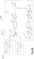
- each patch antennas 14a-14c, 16a-16c may include well-known diversity electronics 50 on the circuit board of the patch antenna 14a-14c ( Figures 2A ) or patch antenna 16a-16c ( Figure 2B ).
- the patch antennas 14a-14c, 16a-16c may be connected by two cables to a receiver 75 including the diversity electronics 50 ( Figure 2C ).
- a cable may extend from one patch antenna element to another for connection at a pin diode switch element 52.
- the output of the patch antenna including the diversity electronics is then output at reference numeral 66.
Landscapes
- Engineering & Computer Science (AREA)
- Computer Networks & Wireless Communication (AREA)
- Signal Processing (AREA)
- Remote Sensing (AREA)
- Physics & Mathematics (AREA)
- Astronomy & Astrophysics (AREA)
- Aviation & Aerospace Engineering (AREA)
- General Physics & Mathematics (AREA)
- Waveguide Aerials (AREA)
- Variable-Direction Aerials And Aerial Arrays (AREA)
- Details Of Aerials (AREA)
Claims (25)
- Satellitenantennenmodul (12a-12c), das aufweist:zumindest ein Antennenelement (14a-14c, 16a-16c) und eine Masseebene (18a-18c), wobei die Antenne auf der Masseebene (18a-18c) angeordnet ist, wobei die Masseebene (18a-18c) konfiguriert ist, kapazitiv mit einer Fahrzeugoberfläche (22a-22c) gekoppelt zu sein, wobei die Masseebene (18a-18c) konfiguriert ist, über der Fahrzeugoberfläche (22a-22c) in einem Elevationswinkel (θ1 - θ4, Δ1, Δ2) angeordnet zu sein, der einen höheren Gewinn des zumindest einen Antennenelements (14a-14c, 16a-16c) erreicht;wobei die Masseebene (18a-18c) eine erste Oberfläche (26a-26c) und eine zweite Oberfläche (28a-28c) umfasst, die an einer Spitze (30a-30c) verbunden sind.
- Das Satellitenantennenmodul (12a-12c) gemäß Anspruch 1, wobei die Masseebene (18a-18c) eine Schicht aus leitfähigem leichten Metall umfasst.
- Das Satellitenantennenmodul (12a-12c) gemäß Anspruch 1, wobei der Elevationswinkel (θ1 - θ4, Δ1, Δ2) zwischen etwa 5° - 60° liegt.
- Das Satellitenantennenmodul (12a-12c) gemäß Anspruch 1, wobei das zumindest eine Antennenelement (14a-14c, 16a-16c) integrierte Diversitätselektronik (50) umfasst.
- Das Satellitenantennenmodul (12a-12c) gemäß Anspruch 1, wobei das zumindest eine Antennenelement (14a-14c, 16a-16c) konfiguriert ist zum Empfangen von Satellitensignalen zwischen einem Frequenzbereich von etwa 2320-2345 MHz.
- Das Satellitenantennenmodul (12a-12c) gemäß Anspruch 1, wobei das zumindest eine Antennenelement (14a-14c, 16a-16c) eine Patchantenne, eine Helixantenne oder eine Monopolantenne ist, die konfiguriert ist zum Empfangen von terrestrischen und Satellitensignalen.
- Ein Satellitenantennenmodul (12c) gemäß Anspruch 1, wobei das zumindest eine Antennenelement ein Patchantennenelement (14c, 16c) ist, und wobei die Masseebene (18c) konfiguriert ist, über der Fahrzeugoberfläche (22c) in einem anpassbaren Elevationswinkel (Δ1, Δ2) angeordnet zu sein.
- Das Satellitenantennenmodul (12c) gemäß Anspruch 7, wobei die Masseebene (18c) eine Schicht aus leitfähigem leichten Metall umfasst.
- Das Satellitenantennenmodul (12c) gemäß Anspruch 7, wobei die erste Oberfläche (26c) und die zweite Oberfläche (28c) der Masseebene an einer Spitze (30c) verbunden sind, wobei zumindest ein Patchantennenelement (14c, 16c) auf einer der ersten oder zweiten Oberfläche (26c, 28c) angeordnet ist, wobei ein Eckpunkt (24) konfiguriert ist, an einem Ende von einer der ersten oder zweiten Oberfläche (26c, 28c) nahe der Fahrzeugoberfläche (22c) angeordnet zu sein, um zu ermöglichen, dass die Masseebene (18c) rekonfiguriert wird, um den anpassbaren Elevationswinkel (Δ1, Δ2) zu ändern.
- Das Satellitenantennenmodul (12c) gemäß Anspruch 7, wobei der Elevationswinkel (Δ1, Δ2) zwischen etwa 5° - 60° liegt.
- Das Satellitenantennenmodul (12c) gemäß Anspruch 7, wobei das zumindest eine Patchantennenelement (14c, 16c) integrierte Diversitätselektronik (50) umfasst.
- Das Satellitenantennenmodul (12c) gemäß Anspruch 7, wobei das zumindest eine Patchantennenelement (14c, 16c) konfiguriert ist zum Empfangen von Satellitensignalen zwischen einem Frequenzbereich von etwa 2320-2345 MHz.
- Ein Satellitenantennenmodul (12a-12c) gemäß Anspruch 1, wobei ein erstes Patchantennenelement (14a - 14c) auf der ersten Oberfläche (26a-26b) der Masseebene angeordnet ist und ein zweites Patchantennenelement (16a-16c) auf der zweiten Oberfläche (28a-28c) angeordnet ist.
- Das Satellitenantennenmodul (12a-12c) gemäß Anspruch 13, wobei die Masseebene (18a-18c) eine Schicht aus leitfähigem leichten Metall umfasst.
- Das Satellitenantennenmodul (12a-12c) gemäß Anspruch 13, wobei der Elevationswinkel (θ1 - θ4, Δ1, Δ2) zwischen etwa 5° - 60° liegt.
- Das Satellitenantennenmodul (12a-12c) gemäß Anspruch 13, wobei eines der ersten und zweiten Patchantennenelemente (14a-14c, 16a-16c) integrierte Diversitätselektronik (50) umfasst, wobei die ersten und zweiten Patchantennenelemente (14a-14c) durch ein einzelnes Kabel verbunden sind derart, dass die Antennenelemente in einer Diversitätsantennenkonfiguration arbeiten.
- Das Satellitenantennenmodul (12a-12c) gemäß Anspruch 13, wobei die ersten und zweiten Patchantennen (14a-14c, 16a-16c) konfiguriert sind zum Empfangen von Satellitensignalen zwischen einem Frequenzbereich von etwa 2320-2345 MHz.
- Das Satellitenantennenmodul (12a-12c) gemäß Anspruch 16, wobei die Masseebene (18a-18c) eine Schicht aus leitfähigem leichten Metall umfasst.
- Das Satellitenantennenmodul (12a-12c) gemäß Anspruch 16, wobei der Elevationswinkel (θ1 - θ4, Δ1, Δ2) zwischen etwa 5° - 60° liegt.
- Das Satellitenantennenmodul (12a-12c) gemäß Anspruch 16, wobei die ersten und zweiten Patchantennen (14a-14c, 16a-16c) konfiguriert sind zum Empfangen von Satellitensignalen zwischen einem Frequenzbereich von etwa 2320-2345 MHz.
- Ein Antennensystem, das aufweist:zwei oder mehr Patchantennenelemente (14a-14c, 16a-16c) und zwei oder mehr Masseebenen (18a-18c), wobei die zwei oder mehr Patchantennenelemente (14a-14c, 16a-16c) jeweils auf den zwei oder mehr Masseebenen (18a-18c) angeordnet sind, wobei die zwei oder mehr Masseebenen (18a-18c) konfiguriert sind, kapazitiv mit einer Fahrzeugoberfläche (22a-22c) gekoppelt zu sein, wobei die zwei oder mehr Masseebenen (18a-18c) konfiguriert sind, über der Fahrzeugoberfläche (22a-22c) in einem Elevationswinkel (θ1 - θ4, Δ1, Δ2) angeordnet zu sein, der einen höheren Gewinn der zwei oder mehr Patchantennenelemente (14a-14c, 16a-16c) erreicht, wobei die zwei oder mehr Patchantennenelemente (14a-14c, 16a-16c) in einer Diversitätsantennenkonfiguration arbeiten; wobei die Masseebenen (18a-18c) an einer Spitze (30a-30c) verbunden sind.
- Das Antennensystem gemäß Anspruch 21, wobei die zwei oder mehr Masseebenen (18a-18c) eine Schicht aus leitfähigem leichten Metall umfassen.
- Das Antennensystem gemäß Anspruch 21, wobei der Elevationswinkel (θ1 - θ4, Δ1, Δ2) zwischen etwa 5° - 60° liegt.
- Das Antennensystem gemäß Anspruch 21, wobei zumindest eines der zwei oder mehr Patchantennenelemente (14a- 14c, 16a-16c) integrierte Diversitätselektronik (50) umfasst.
- Das Antennensystem gemäß Anspruch 21, wobei die zwei oder mehr Patchantennenelemente (14a- 14c, 16a-16c) konfiguriert sind zum Empfangen von Satellitensignalen zwischen einem Frequenzbereich von etwa 2320-2345 MHz.
Applications Claiming Priority (1)
| Application Number | Priority Date | Filing Date | Title |
|---|---|---|---|
| US11/179,866 US7245261B2 (en) | 2005-07-12 | 2005-07-12 | Satellite diversity antenna system |
Publications (2)
| Publication Number | Publication Date |
|---|---|
| EP1744470A1 EP1744470A1 (de) | 2007-01-17 |
| EP1744470B1 true EP1744470B1 (de) | 2017-10-11 |
Family
ID=36678373
Family Applications (1)
| Application Number | Title | Priority Date | Filing Date |
|---|---|---|---|
| EP06076283.8A Active EP1744470B1 (de) | 2005-07-12 | 2006-06-22 | Antennensystem mit Satellitendiversität |
Country Status (2)
| Country | Link |
|---|---|
| US (1) | US7245261B2 (de) |
| EP (1) | EP1744470B1 (de) |
Families Citing this family (35)
| Publication number | Priority date | Publication date | Assignee | Title |
|---|---|---|---|---|
| DE102004035064A1 (de) | 2004-07-20 | 2006-02-16 | Receptec Gmbh | Antennenmodul |
| FR2875952B1 (fr) * | 2004-09-28 | 2008-11-28 | Thales Sa | Systeme antennaire integre de telecommunications spatiales pour les stations terrestres mobiles (satcoms) |
| CA2552303A1 (en) * | 2005-07-15 | 2007-01-15 | M/A-Com, Inc. | Fixed tiltable antenna device |
| US7277056B1 (en) * | 2006-09-15 | 2007-10-02 | Laird Technologies, Inc. | Stacked patch antennas |
| US8111196B2 (en) * | 2006-09-15 | 2012-02-07 | Laird Technologies, Inc. | Stacked patch antennas |
| US7411560B2 (en) * | 2006-09-30 | 2008-08-12 | M/A-Com, Inc. | Low profile antennas and devices |
| US8712563B2 (en) * | 2006-10-24 | 2014-04-29 | Slacker, Inc. | Method and apparatus for interactive distribution of digital content |
| US10657168B2 (en) | 2006-10-24 | 2020-05-19 | Slacker, Inc. | Methods and systems for personalized rendering of digital media content |
| EP2080114A4 (de) | 2006-10-24 | 2012-02-01 | Slacker Inc | Verfahren und vorrichtung zur wiedergabe digitaler medieninhalte |
| ATE431627T1 (de) * | 2006-11-03 | 2009-05-15 | Delphi Tech Inc | Montagebaugruppe für eine kraftfahrzeugantenne |
| WO2008101227A1 (en) * | 2007-02-15 | 2008-08-21 | Slacker, Inc. | Methods for satellite augmented wireless communication networks |
| WO2008106624A2 (en) * | 2007-02-28 | 2008-09-04 | Slacker, Inc. | Antenna array for a hi/lo antenna beam pattern and method of utilization |
| WO2008109889A1 (en) | 2007-03-08 | 2008-09-12 | Slacker, Inc. | System and method for personalizing playback content through interaction with a playback device |
| WO2008112924A2 (en) * | 2007-03-14 | 2008-09-18 | Slacker, Inc. | Systems and methods for portable personalized radio |
| FR2951585B1 (fr) * | 2009-10-20 | 2012-05-25 | Ineo Defense | Plan masse pour antennes notamment pour antennes emettant des signaux de brouillage |
| EP2317603A1 (de) * | 2009-10-29 | 2011-05-04 | Delphi Technologies, Inc. | Multistandard-Antennenmodul |
| US9091745B2 (en) * | 2012-02-20 | 2015-07-28 | Rockwell Collins, Inc. | Optimized two panel AESA for aircraft applications |
| GB2507503B (en) * | 2012-10-30 | 2016-05-11 | Broadcom Corp | A multiple antenna wireless communication arrangement for a vehicle |
| EP4236606A3 (de) | 2013-02-11 | 2023-10-04 | Gogo Business Aviation LLC | Mehrantennensystem und verfahren für mobile plattformen |
| US10275463B2 (en) | 2013-03-15 | 2019-04-30 | Slacker, Inc. | System and method for scoring and ranking digital content based on activity of network users |
| JP6623522B2 (ja) * | 2015-01-26 | 2019-12-25 | セイコーエプソン株式会社 | ロボット、ロボットシステムおよびサーバー |
| EP3089265B1 (de) * | 2015-04-29 | 2024-03-20 | Swisscom AG | Antennensystem für fahrzeuge |
| DE102015007144A1 (de) * | 2015-06-03 | 2016-12-08 | Audi Ag | Zweitnutzung einer Kraftfahrzeugantenne durch ein E-Call-Steuergerät |
| KR101694261B1 (ko) * | 2015-09-09 | 2017-01-23 | 현대자동차주식회사 | 안테나 장치 및 상기 안테나 장치를 이용하는 차량 |
| WO2017076750A1 (en) | 2015-11-02 | 2017-05-11 | Taoglas Limited | A multi-network telematics device with multiple antennas |
| US9828036B2 (en) | 2015-11-24 | 2017-11-28 | Srg Global Inc. | Active grille shutter system with integrated radar |
| DE102016118629A1 (de) * | 2016-06-09 | 2017-12-14 | Hirschmann Car Communication Gmbh | Kommunikationssystem eines Fahrzeuges mit verbessertem Wärmemanagement |
| EP3285332B1 (de) * | 2016-08-19 | 2019-04-03 | Swisscom AG | Antennensystem |
| TWI662743B (zh) * | 2018-01-15 | 2019-06-11 | 和碩聯合科技股份有限公司 | 天線裝置 |
| GB2572769B (en) * | 2018-04-09 | 2022-12-14 | Airspan Ip Holdco Llc | Moveable antenna apparatus |
| GB2574872B (en) * | 2018-06-21 | 2023-03-22 | Airspan Ip Holdco Llc | Moveable antenna apparatus |
| TWI686997B (zh) * | 2018-09-27 | 2020-03-01 | 啟碁科技股份有限公司 | 天線系統 |
| WO2020095497A1 (ja) * | 2018-11-06 | 2020-05-14 | 住友電気工業株式会社 | アンテナモジュール、及び車両 |
| US12244058B2 (en) * | 2020-01-13 | 2025-03-04 | Lg Electronics Inc. | Antenna system mounted in vehicle |
| TWM628581U (zh) * | 2022-01-11 | 2022-06-21 | 和碩聯合科技股份有限公司 | 陣列天線 |
Family Cites Families (8)
| Publication number | Priority date | Publication date | Assignee | Title |
|---|---|---|---|---|
| US5905467A (en) | 1997-07-25 | 1999-05-18 | Lucent Technologies Inc. | Antenna diversity in wireless communication terminals |
| US6448930B1 (en) | 1999-10-15 | 2002-09-10 | Andrew Corporation | Indoor antenna |
| JP2004056643A (ja) * | 2002-07-23 | 2004-02-19 | Communication Research Laboratory | アンテナ装置 |
| US6806838B2 (en) | 2002-08-14 | 2004-10-19 | Delphi-D Antenna Systems | Combination satellite and terrestrial antenna |
| JP2004235729A (ja) * | 2003-01-28 | 2004-08-19 | Denso Corp | アンテナ装置 |
| JP4337817B2 (ja) * | 2003-04-24 | 2009-09-30 | 旭硝子株式会社 | アンテナ装置 |
| KR100594962B1 (ko) | 2003-10-30 | 2006-06-30 | 한국전자통신연구원 | 위성통신용 안테나 시스템 및 이를 이용한 위성신호 추적방법 |
| FR2875952B1 (fr) | 2004-09-28 | 2008-11-28 | Thales Sa | Systeme antennaire integre de telecommunications spatiales pour les stations terrestres mobiles (satcoms) |
-
2005
- 2005-07-12 US US11/179,866 patent/US7245261B2/en not_active Expired - Lifetime
-
2006
- 2006-06-22 EP EP06076283.8A patent/EP1744470B1/de active Active
Non-Patent Citations (1)
| Title |
|---|
| None * |
Also Published As
| Publication number | Publication date |
|---|---|
| US20070013593A1 (en) | 2007-01-18 |
| US7245261B2 (en) | 2007-07-17 |
| EP1744470A1 (de) | 2007-01-17 |
Similar Documents
| Publication | Publication Date | Title |
|---|---|---|
| EP1744470B1 (de) | Antennensystem mit Satellitendiversität | |
| US6329954B1 (en) | Dual-antenna system for single-frequency band | |
| US7034758B2 (en) | Multifunctional antenna | |
| US6999032B2 (en) | Antenna system employing floating ground plane | |
| US6218997B1 (en) | Antenna for a plurality of radio services | |
| US7633452B2 (en) | Hybrid antenna unit with a suitably located booster circuit | |
| US7132988B2 (en) | Directional patch antenna | |
| US6646618B2 (en) | Low-profile slot antenna for vehicular communications and methods of making and designing same | |
| US6697019B1 (en) | Low-profile dual-antenna system | |
| US11476563B2 (en) | Under-roof antenna modules for vehicle | |
| US6859181B2 (en) | Integrated spiral and top-loaded monopole antenna | |
| EP1011167A1 (de) | Antenneneinheit, kommunikationssystem und digitaler fernsehempfänger | |
| JP4798368B2 (ja) | 複合アンテナ装置 | |
| CN109565109B (zh) | 车载用天线装置 | |
| US6989785B2 (en) | Low-profile, multi-band antenna module | |
| US7038624B2 (en) | Patch antenna with parasitically enhanced perimeter | |
| US6693596B2 (en) | Dual-frequency antenna | |
| KR100787602B1 (ko) | 자동차의 송수신용 통합안테나 모듈 | |
| US20230216218A1 (en) | Onboard antenna module | |
| JP3639845B2 (ja) | 衛星電波及び地上電波受信用アンテナ装置 | |
| US20100001910A1 (en) | On-Vehicle Antenna | |
| JP4230300B2 (ja) | 複合アンテナ装置 | |
| US20100035468A1 (en) | Common integrated circuit for multiple antennas and methods | |
| JP2006173895A (ja) | ダイバーシティアンテナ装置 | |
| KR200406832Y1 (ko) | 라디오방송/지상-디엠비 수신용 통합 안테나 |
Legal Events
| Date | Code | Title | Description |
|---|---|---|---|
| PUAI | Public reference made under article 153(3) epc to a published international application that has entered the european phase |
Free format text: ORIGINAL CODE: 0009012 |
|
| AK | Designated contracting states |
Kind code of ref document: A1 Designated state(s): AT BE BG CH CY CZ DE DK EE ES FI FR GB GR HU IE IS IT LI LT LU LV MC NL PL PT RO SE SI SK TR |
|
| AX | Request for extension of the european patent |
Extension state: AL BA HR MK YU |
|
| 17P | Request for examination filed |
Effective date: 20070717 |
|
| 17Q | First examination report despatched |
Effective date: 20070817 |
|
| AKX | Designation fees paid |
Designated state(s): AT BE BG CH CY CZ DE DK EE ES FI FR GB GR HU IE IS IT LI LT LU LV MC NL PL PT RO SE SI SK TR |
|
| RIC1 | Information provided on ipc code assigned before grant |
Ipc: H01Q 3/06 20060101ALI20170317BHEP Ipc: H04B 7/185 20060101ALI20170317BHEP Ipc: H01Q 1/32 20060101ALI20170317BHEP Ipc: H01Q 21/28 20060101ALI20170317BHEP Ipc: H04B 7/08 20060101AFI20170317BHEP |
|
| GRAP | Despatch of communication of intention to grant a patent |
Free format text: ORIGINAL CODE: EPIDOSNIGR1 |
|
| INTG | Intention to grant announced |
Effective date: 20170508 |
|
| GRAS | Grant fee paid |
Free format text: ORIGINAL CODE: EPIDOSNIGR3 |
|
| GRAA | (expected) grant |
Free format text: ORIGINAL CODE: 0009210 |
|
| AK | Designated contracting states |
Kind code of ref document: B1 Designated state(s): AT BE BG CH CY CZ DE DK EE ES FI FR GB GR HU IE IS IT LI LT LU LV MC NL PL PT RO SE SI SK TR |
|
| REG | Reference to a national code |
Ref country code: GB Ref legal event code: FG4D |
|
| REG | Reference to a national code |
Ref country code: CH Ref legal event code: EP |
|
| REG | Reference to a national code |
Ref country code: IE Ref legal event code: FG4D |
|
| REG | Reference to a national code |
Ref country code: AT Ref legal event code: REF Ref document number: 936875 Country of ref document: AT Kind code of ref document: T Effective date: 20171115 |
|
| REG | Reference to a national code |
Ref country code: DE Ref legal event code: R096 Ref document number: 602006053825 Country of ref document: DE |
|
| REG | Reference to a national code |
Ref country code: NL Ref legal event code: MP Effective date: 20171011 |
|
| REG | Reference to a national code |
Ref country code: LT Ref legal event code: MG4D |
|
| REG | Reference to a national code |
Ref country code: AT Ref legal event code: MK05 Ref document number: 936875 Country of ref document: AT Kind code of ref document: T Effective date: 20171011 |
|
| PG25 | Lapsed in a contracting state [announced via postgrant information from national office to epo] |
Ref country code: NL Free format text: LAPSE BECAUSE OF FAILURE TO SUBMIT A TRANSLATION OF THE DESCRIPTION OR TO PAY THE FEE WITHIN THE PRESCRIBED TIME-LIMIT Effective date: 20171011 |
|
| PG25 | Lapsed in a contracting state [announced via postgrant information from national office to epo] |
Ref country code: LT Free format text: LAPSE BECAUSE OF FAILURE TO SUBMIT A TRANSLATION OF THE DESCRIPTION OR TO PAY THE FEE WITHIN THE PRESCRIBED TIME-LIMIT Effective date: 20171011 Ref country code: SE Free format text: LAPSE BECAUSE OF FAILURE TO SUBMIT A TRANSLATION OF THE DESCRIPTION OR TO PAY THE FEE WITHIN THE PRESCRIBED TIME-LIMIT Effective date: 20171011 Ref country code: FI Free format text: LAPSE BECAUSE OF FAILURE TO SUBMIT A TRANSLATION OF THE DESCRIPTION OR TO PAY THE FEE WITHIN THE PRESCRIBED TIME-LIMIT Effective date: 20171011 Ref country code: ES Free format text: LAPSE BECAUSE OF FAILURE TO SUBMIT A TRANSLATION OF THE DESCRIPTION OR TO PAY THE FEE WITHIN THE PRESCRIBED TIME-LIMIT Effective date: 20171011 |
|
| PG25 | Lapsed in a contracting state [announced via postgrant information from national office to epo] |
Ref country code: BG Free format text: LAPSE BECAUSE OF FAILURE TO SUBMIT A TRANSLATION OF THE DESCRIPTION OR TO PAY THE FEE WITHIN THE PRESCRIBED TIME-LIMIT Effective date: 20180111 Ref country code: AT Free format text: LAPSE BECAUSE OF FAILURE TO SUBMIT A TRANSLATION OF THE DESCRIPTION OR TO PAY THE FEE WITHIN THE PRESCRIBED TIME-LIMIT Effective date: 20171011 Ref country code: GR Free format text: LAPSE BECAUSE OF FAILURE TO SUBMIT A TRANSLATION OF THE DESCRIPTION OR TO PAY THE FEE WITHIN THE PRESCRIBED TIME-LIMIT Effective date: 20180112 Ref country code: IS Free format text: LAPSE BECAUSE OF FAILURE TO SUBMIT A TRANSLATION OF THE DESCRIPTION OR TO PAY THE FEE WITHIN THE PRESCRIBED TIME-LIMIT Effective date: 20180211 Ref country code: LV Free format text: LAPSE BECAUSE OF FAILURE TO SUBMIT A TRANSLATION OF THE DESCRIPTION OR TO PAY THE FEE WITHIN THE PRESCRIBED TIME-LIMIT Effective date: 20171011 |
|
| REG | Reference to a national code |
Ref country code: DE Ref legal event code: R097 Ref document number: 602006053825 Country of ref document: DE |
|
| PG25 | Lapsed in a contracting state [announced via postgrant information from national office to epo] |
Ref country code: DK Free format text: LAPSE BECAUSE OF FAILURE TO SUBMIT A TRANSLATION OF THE DESCRIPTION OR TO PAY THE FEE WITHIN THE PRESCRIBED TIME-LIMIT Effective date: 20171011 Ref country code: SK Free format text: LAPSE BECAUSE OF FAILURE TO SUBMIT A TRANSLATION OF THE DESCRIPTION OR TO PAY THE FEE WITHIN THE PRESCRIBED TIME-LIMIT Effective date: 20171011 Ref country code: CZ Free format text: LAPSE BECAUSE OF FAILURE TO SUBMIT A TRANSLATION OF THE DESCRIPTION OR TO PAY THE FEE WITHIN THE PRESCRIBED TIME-LIMIT Effective date: 20171011 Ref country code: EE Free format text: LAPSE BECAUSE OF FAILURE TO SUBMIT A TRANSLATION OF THE DESCRIPTION OR TO PAY THE FEE WITHIN THE PRESCRIBED TIME-LIMIT Effective date: 20171011 |
|
| PLBE | No opposition filed within time limit |
Free format text: ORIGINAL CODE: 0009261 |
|
| STAA | Information on the status of an ep patent application or granted ep patent |
Free format text: STATUS: NO OPPOSITION FILED WITHIN TIME LIMIT |
|
| PG25 | Lapsed in a contracting state [announced via postgrant information from national office to epo] |
Ref country code: PL Free format text: LAPSE BECAUSE OF FAILURE TO SUBMIT A TRANSLATION OF THE DESCRIPTION OR TO PAY THE FEE WITHIN THE PRESCRIBED TIME-LIMIT Effective date: 20171011 Ref country code: RO Free format text: LAPSE BECAUSE OF FAILURE TO SUBMIT A TRANSLATION OF THE DESCRIPTION OR TO PAY THE FEE WITHIN THE PRESCRIBED TIME-LIMIT Effective date: 20171011 Ref country code: IT Free format text: LAPSE BECAUSE OF FAILURE TO SUBMIT A TRANSLATION OF THE DESCRIPTION OR TO PAY THE FEE WITHIN THE PRESCRIBED TIME-LIMIT Effective date: 20171011 |
|
| 26N | No opposition filed |
Effective date: 20180712 |
|
| PG25 | Lapsed in a contracting state [announced via postgrant information from national office to epo] |
Ref country code: SI Free format text: LAPSE BECAUSE OF FAILURE TO SUBMIT A TRANSLATION OF THE DESCRIPTION OR TO PAY THE FEE WITHIN THE PRESCRIBED TIME-LIMIT Effective date: 20171011 |
|
| REG | Reference to a national code |
Ref country code: DE Ref legal event code: R081 Ref document number: 602006053825 Country of ref document: DE Owner name: APTIV TECHNOLOGIES LIMITED, BB Free format text: FORMER OWNER: DELPHI TECHNOLOGIES, INC., TROY, MICH., US |
|
| REG | Reference to a national code |
Ref country code: CH Ref legal event code: PL |
|
| GBPC | Gb: european patent ceased through non-payment of renewal fee |
Effective date: 20180622 |
|
| REG | Reference to a national code |
Ref country code: BE Ref legal event code: MM Effective date: 20180630 |
|
| REG | Reference to a national code |
Ref country code: IE Ref legal event code: MM4A |
|
| PG25 | Lapsed in a contracting state [announced via postgrant information from national office to epo] |
Ref country code: MC Free format text: LAPSE BECAUSE OF FAILURE TO SUBMIT A TRANSLATION OF THE DESCRIPTION OR TO PAY THE FEE WITHIN THE PRESCRIBED TIME-LIMIT Effective date: 20171011 Ref country code: LU Free format text: LAPSE BECAUSE OF NON-PAYMENT OF DUE FEES Effective date: 20180622 |
|
| PG25 | Lapsed in a contracting state [announced via postgrant information from national office to epo] |
Ref country code: CH Free format text: LAPSE BECAUSE OF NON-PAYMENT OF DUE FEES Effective date: 20180630 Ref country code: IE Free format text: LAPSE BECAUSE OF NON-PAYMENT OF DUE FEES Effective date: 20180622 Ref country code: GB Free format text: LAPSE BECAUSE OF NON-PAYMENT OF DUE FEES Effective date: 20180622 Ref country code: LI Free format text: LAPSE BECAUSE OF NON-PAYMENT OF DUE FEES Effective date: 20180630 Ref country code: FR Free format text: LAPSE BECAUSE OF NON-PAYMENT OF DUE FEES Effective date: 20180630 |
|
| PG25 | Lapsed in a contracting state [announced via postgrant information from national office to epo] |
Ref country code: BE Free format text: LAPSE BECAUSE OF NON-PAYMENT OF DUE FEES Effective date: 20180630 |
|
| PG25 | Lapsed in a contracting state [announced via postgrant information from national office to epo] |
Ref country code: TR Free format text: LAPSE BECAUSE OF FAILURE TO SUBMIT A TRANSLATION OF THE DESCRIPTION OR TO PAY THE FEE WITHIN THE PRESCRIBED TIME-LIMIT Effective date: 20171011 |
|
| PG25 | Lapsed in a contracting state [announced via postgrant information from national office to epo] |
Ref country code: HU Free format text: LAPSE BECAUSE OF FAILURE TO SUBMIT A TRANSLATION OF THE DESCRIPTION OR TO PAY THE FEE WITHIN THE PRESCRIBED TIME-LIMIT; INVALID AB INITIO Effective date: 20060622 Ref country code: PT Free format text: LAPSE BECAUSE OF FAILURE TO SUBMIT A TRANSLATION OF THE DESCRIPTION OR TO PAY THE FEE WITHIN THE PRESCRIBED TIME-LIMIT Effective date: 20171011 |
|
| PG25 | Lapsed in a contracting state [announced via postgrant information from national office to epo] |
Ref country code: CY Free format text: LAPSE BECAUSE OF FAILURE TO SUBMIT A TRANSLATION OF THE DESCRIPTION OR TO PAY THE FEE WITHIN THE PRESCRIBED TIME-LIMIT Effective date: 20171011 |
|
| P01 | Opt-out of the competence of the unified patent court (upc) registered |
Effective date: 20230425 |
|
| REG | Reference to a national code |
Ref country code: DE Ref legal event code: R081 Ref document number: 602006053825 Country of ref document: DE Owner name: APTIV TECHNOLOGIES AG, CH Free format text: FORMER OWNER: APTIV TECHNOLOGIES LIMITED, ST. MICHAEL, BB |
|
| PGFP | Annual fee paid to national office [announced via postgrant information from national office to epo] |
Ref country code: DE Payment date: 20250519 Year of fee payment: 20 |