EP1744360A2 - Heatsink with adapted backplate - Google Patents
Heatsink with adapted backplate Download PDFInfo
- Publication number
- EP1744360A2 EP1744360A2 EP06076400A EP06076400A EP1744360A2 EP 1744360 A2 EP1744360 A2 EP 1744360A2 EP 06076400 A EP06076400 A EP 06076400A EP 06076400 A EP06076400 A EP 06076400A EP 1744360 A2 EP1744360 A2 EP 1744360A2
- Authority
- EP
- European Patent Office
- Prior art keywords
- backplate
- heatsink
- ribs
- grooves
- adhesive material
- Prior art date
- Legal status (The legal status is an assumption and is not a legal conclusion. Google has not performed a legal analysis and makes no representation as to the accuracy of the status listed.)
- Withdrawn
Links
Images

Classifications
-
- H—ELECTRICITY
- H10—SEMICONDUCTOR DEVICES; ELECTRIC SOLID-STATE DEVICES NOT OTHERWISE PROVIDED FOR
- H10W—GENERIC PACKAGES, INTERCONNECTIONS, CONNECTORS OR OTHER CONSTRUCTIONAL DETAILS OF DEVICES COVERED BY CLASS H10
- H10W40/00—Arrangements for thermal protection or thermal control
- H10W40/40—Arrangements for thermal protection or thermal control involving heat exchange by flowing fluids
- H10W40/47—Arrangements for thermal protection or thermal control involving heat exchange by flowing fluids by flowing liquids, e.g. forced water cooling
-
- H—ELECTRICITY
- H10—SEMICONDUCTOR DEVICES; ELECTRIC SOLID-STATE DEVICES NOT OTHERWISE PROVIDED FOR
- H10W—GENERIC PACKAGES, INTERCONNECTIONS, CONNECTORS OR OTHER CONSTRUCTIONAL DETAILS OF DEVICES COVERED BY CLASS H10
- H10W40/00—Arrangements for thermal protection or thermal control
- H10W40/20—Arrangements for cooling
- H10W40/22—Arrangements for cooling characterised by their shape, e.g. having conical or cylindrical projections
Definitions
- the present invention relates to the field of heatsinks, heatpipes, radiators and cooling units, and particularly to metallic heatsinks for cooling electronic power modules and transistors in automotive, motor vehicle and under the hood applications and the like, and to methods of producing the same.
- Electronic components including electronic power modules and transistors to control the engine and/or for other under the hood functions, are in wide use in the automotive and motor vehicle industry. Such electronic components typically need to be cooled by means of heatsinks or heatpipes placed immediately adjacent to them.
- heatsinks including transistors, such as FETs, or some types of semiconductors and silicon chips or the like, generate heat and must be cooled for effective use over a period of time.
- the heatsinks using a fluid or liquid as a coolant medium the heatsink needs to contain the fluid and therefore has a backplate, typically arranged away from the electronic component to be cooled. Often water, or water laced with a chemical, is used as such coolant.
- a fluid-cooled heatsink and backplate are provided, the backplate formed with a set of grooves, and the heatsink formed with a first set of ribs corresponding to the set of grooves and extending into and affixed to the set of grooves.
- the heatsink and backplate may also include one or more glue material or adhesive material disposed between the first set of ribs and the set of grooves to secure the backplate to the heatsink.
- the adhesive material may be a silicone-adhesive material.
- a second set of ribs extending from the heatsink may also be included, such that a distal end of each rib of the second set of ribs lines up away from each groove of the plurality of grooves and such that space is allowed between each rib of the second set of ribs and the backplate.
- An epoxy-adhesive material may be disposed between the second set of ribs and the backplate.
- a silicone adhesive material may be provided between the first set of ribs and the grooves to secure the backplate to the heatsink, and the second set of ribs may be welded or partially welded to the grooves.
- a set of silicone o-rings may be arranged in the sealing gaps between the grooves and the first set of ribs. Further, the first set of ribs may be welded or partially welded to the grooves.
- Stand-off pins may also be inserted to secure the backplate to the heatsink.
- the stand-off pins may be made of aluminum, aluminum alloy or steel.
- the coolant fluid may be water or primarily water.
- the heatsink and backplate may be die-cast or otherwise formed of aluminum or aluminum alloy. Such a heatsink and backplate would be typically adapted for an electronic power module in an automotive application.
- Figure 1 is a sectional view of a heatsink with backplate, according to an aspect of the present invention.
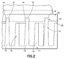
- Figure 2 is a close-up sectional view of ribs of the heatsink in engagement position with the backplate, according to an aspect of the present invention.
- FIG. I is a cross-sectional schematic illustration of the heatsink with the backplate 20.
- the heatsink 10 includes a set of ribs or fins, such that each rib 13 extends out toward the backplate 20.
- Backplate 20 has a series of recesses or grooves 21 formed in the backplate 20 for receiving the ribs of the heatsink 10.
- the rib 13 and the other ribs of the heatsink are shown as tapered toward the backplate, but it will be understood that ribs with other shapes, such as rectangular or cylindrical ribs, are also contemplated.
- backplate 20 is formed during its manufacture with the grooves 21 in place.
- the backplate 20 may be made primarily of aluminum or aluminum alloy and molded or machined with the grooves 21.
- the backplate 20 is manufactured by well-known die casting methods.
- the heatsink 10 is formed integrally with the ribs 13 or fins, and may be made of metals, such as aluminum or aluminum alloy.
- such a heat sink with backplate would be designed to withstand more than three bar pressure.
- adhesive material 14 such as a glue, epoxy or resin, shown in black, is introduced into the groove 21 to secure the rib 13.
- the grooves with the adhesive material 14 are then mated with the ribs to secure the backplate 20 to the heatsink 10.
- the ribs or fins can also be attached or affixed via a silicone adhesive or by using a silicone o-ring pressed into the sealing gap.
- the steps of securing the backplate 20 to the heatsink 10 may be varied: the adhesive or the o-ring can be placed on or around the distal end 30 of the ribs 13 (and the distal ends of the remaining ribs) and then the ribs can be inserted into the grooves of the backplate 20.
- each short rib 15 is adjacent to the taller ribs (the taller ribs are the ribs in mating position with the grooves of the backplate 20) in an alternating pattern.
- the short rib 15 may be affixed to the backplate to provide additional strength to the heatsink backplate combination.
- the short ribs may be adhered using an adhesive or glue or may be welded or partially welded at or near the distal ends of the short ribs.
- bolts or stand-off pins also made of metal, such as aluminum, aluminum alloy or steel, may be pressed into the heatsink and the backplate to define the thickness of the adhesive and to provide additional strength during the assembly step. That is, by using a limited number of such pins during the assembly of the heatsink with backplate 20, including during the curing of the glue, adhesive or o-ring, or during the welding of the fins to the backplate, the backplate and the fins would already be one unit. Thus, during the curing step and/or the welding step, the heatsink 10 and backplate 20 would be held in position without additional fixture. However, it will be understood that these means for affixing the backplate 20 to the heatsink 10 could be varied, alternated, or otherwise combined, as would be understood by a person of ordinary skill.
- such a heat sink with backplate, die cast or otherwise formed in two parts can provide a lower-priced and space-saving design and may require no additional screws. This could facilitate more effective use of the cooling channels.
Landscapes
- Cooling Or The Like Of Semiconductors Or Solid State Devices (AREA)
- Cooling Or The Like Of Electrical Apparatus (AREA)
- Standing Axle, Rod, Or Tube Structures Coupled By Welding, Adhesion, Or Deposition (AREA)
Abstract
Description
- This application is based on and claims benefit of
United States Provisional Application No. 60/698,644, filed on July 12, 2005 - The present invention relates to the field of heatsinks, heatpipes, radiators and cooling units, and particularly to metallic heatsinks for cooling electronic power modules and transistors in automotive, motor vehicle and under the hood applications and the like, and to methods of producing the same.
- Electronic components, including electronic power modules and transistors to control the engine and/or for other under the hood functions, are in wide use in the automotive and motor vehicle industry. Such electronic components typically need to be cooled by means of heatsinks or heatpipes placed immediately adjacent to them. For example, certain types of electronic power modules, including transistors, such as FETs, or some types of semiconductors and silicon chips or the like, generate heat and must be cooled for effective use over a period of time. For heatsinks using a fluid or liquid as a coolant medium, the heatsink needs to contain the fluid and therefore has a backplate, typically arranged away from the electronic component to be cooled. Often water, or water laced with a chemical, is used as such coolant.
- However, attaching and securing the backplate to the heatsink to achieve a degree of mechanical strength poses a number of challenges. Screws, glue or other affixing means for the attachment of the backplate to the heatsink may be used, however placing glue or adhesive on the distal ends of the ribs or fins of the backplate is not always sufficient to secure the backplate to the heatsink properly. Screws and other affixing means can take up valuable space from the cooling channels inside the heatsink, and the use of many parts for assembly could require additional inventory and expense. A streamlined, simple design that saves space, including space in the cooling channel, would be advantageous.
- A fluid-cooled heatsink and backplate are provided, the backplate formed with a set of grooves, and the heatsink formed with a first set of ribs corresponding to the set of grooves and extending into and affixed to the set of grooves.
- The heatsink and backplate may also include one or more glue material or adhesive material disposed between the first set of ribs and the set of grooves to secure the backplate to the heatsink. For example, the adhesive material may be a silicone-adhesive material.
- A second set of ribs extending from the heatsink may also be included, such that a distal end of each rib of the second set of ribs lines up away from each groove of the plurality of grooves and such that space is allowed between each rib of the second set of ribs and the backplate. An epoxy-adhesive material may be disposed between the second set of ribs and the backplate. Also, a silicone adhesive material may be provided between the first set of ribs and the grooves to secure the backplate to the heatsink, and the second set of ribs may be welded or partially welded to the grooves. Moreover, a set of silicone o-rings may be arranged in the sealing gaps between the grooves and the first set of ribs. Further, the first set of ribs may be welded or partially welded to the grooves.
- Stand-off pins may also be inserted to secure the backplate to the heatsink. The stand-off pins may be made of aluminum, aluminum alloy or steel.
- The coolant fluid may be water or primarily water. The heatsink and backplate may be die-cast or otherwise formed of aluminum or aluminum alloy. Such a heatsink and backplate would be typically adapted for an electronic power module in an automotive application.
- Other features and advantages of the present invention will become apparent from the following description of the invention which refers to the accompanying drawings.
- Figure 1 is a sectional view of a heatsink with backplate, according to an aspect of the present invention.
- Figure 2 is a close-up sectional view of ribs of the heatsink in engagement position with the backplate, according to an aspect of the present invention.
- Figure I is a cross-sectional schematic illustration of the heatsink with the
backplate 20. Theheatsink 10 includes a set of ribs or fins, such that eachrib 13 extends out toward thebackplate 20.Backplate 20 has a series of recesses orgrooves 21 formed in thebackplate 20 for receiving the ribs of theheatsink 10. Therib 13 and the other ribs of the heatsink are shown as tapered toward the backplate, but it will be understood that ribs with other shapes, such as rectangular or cylindrical ribs, are also contemplated. Typically,backplate 20 is formed during its manufacture with thegrooves 21 in place. For example, thebackplate 20 may be made primarily of aluminum or aluminum alloy and molded or machined with thegrooves 21. Typically, thebackplate 20 is manufactured by well-known die casting methods. Similarly, theheatsink 10 is formed integrally with theribs 13 or fins, and may be made of metals, such as aluminum or aluminum alloy. Typically, such a heat sink with backplate would be designed to withstand more than three bar pressure. - Referring to Figure 2,
adhesive material 14 , such as a glue, epoxy or resin, shown in black, is introduced into thegroove 21 to secure therib 13. The grooves with theadhesive material 14 are then mated with the ribs to secure thebackplate 20 to theheatsink 10. However the ribs or fins can also be attached or affixed via a silicone adhesive or by using a silicone o-ring pressed into the sealing gap. It will be understood that the steps of securing thebackplate 20 to theheatsink 10 may be varied: the adhesive or the o-ring can be placed on or around thedistal end 30 of the ribs 13 (and the distal ends of the remaining ribs) and then the ribs can be inserted into the grooves of thebackplate 20. - Also shown in Figures 1 and 2 are a set of short ribs extending from the
heatsink 10. Eachshort rib 15 is adjacent to the taller ribs (the taller ribs are the ribs in mating position with the grooves of the backplate 20) in an alternating pattern. Theshort rib 15 may be affixed to the backplate to provide additional strength to the heatsink backplate combination. The short ribs may be adhered using an adhesive or glue or may be welded or partially welded at or near the distal ends of the short ribs. - Further, bolts or stand-off pins, also made of metal, such as aluminum, aluminum alloy or steel, may be pressed into the heatsink and the backplate to define the thickness of the adhesive and to provide additional strength during the assembly step. That is, by using a limited number of such pins during the assembly of the heatsink with
backplate 20, including during the curing of the glue, adhesive or o-ring, or during the welding of the fins to the backplate, the backplate and the fins would already be one unit. Thus, during the curing step and/or the welding step, theheatsink 10 andbackplate 20 would be held in position without additional fixture. However, it will be understood that these means for affixing thebackplate 20 to theheatsink 10 could be varied, alternated, or otherwise combined, as would be understood by a person of ordinary skill. - Accordingly, such a heat sink with backplate, die cast or otherwise formed in two parts, can provide a lower-priced and space-saving design and may require no additional screws. This could facilitate more effective use of the cooling channels.
- Although the present invention has been described in relation to particular embodiments thereof, many other variations, modifications and other combinations features described, and other uses and applications will become apparent to those skilled in the art. It is preferred, therefore, that the present invention be limited not by the specific disclosure herein, but only by the appended claims.
Claims (16)
- A fluid-cooled heatsink and backplate comprising:the backplate formed with a plurality of grooves; andthe heatsink formed with a first plurality of ribs corresponding to the plurality of grooves and extending into and affixed to the plurality of grooves.
- The heatsink and backplate of claim 1, further comprising at least one of a glue material or an adhesive material disposed between the first plurality of ribs and the plurality of grooves to secure the backplate to the heatsink.
- The heatsink and backplate of claim 2, wherein the at least one of a glue material or an adhesive material comprises a silicone-adhesive material.
- The heatsink and backplate of claim 1, 2 or 3, further comprising a second plurality of ribs extending from the heatsink disposed such that a distal end of each rib of the second plurality of ribs lines up away from each groove of the plurality of grooves and such that space is allowed between each rib of the second plurality of ribs and the backplate.
- The heatsink and backplate of claim 4, further comprising an epoxy-adhesive material disposed between the second plurality of ribs and the backplate.
- The heatsink and backplate of claim 4, further comprising at least one of a silicone adhesive material disposed between the first plurality of ribs and the plurality of grooves to secure the backplate to the heatsink, wherein the second plurality of ribs are at least one of welded or partially welded to the plurality of grooves.
- The heatsink and backplate of any of claims 1-6, further comprising a plurality of silicone o-rings disposed in a plurality of sealing gaps between the plurality of grooves and the first plurality of ribs.
- The heatsink and backplate of any of claims 1-7, wherein the first plurality of ribs are at least one of welded or partially welded to the plurality of grooves.
- The heatsink and backplate of any of claims 1-8, further comprising stand-off pins securing the backplate to the heatsink.
- The heatsink and backplate of claim 9, wherein the stand-off pins and/or heatsink, and/or backplate are comprised of one of aluminum, aluminum alloy or steel.
- The heatsink and backplate of claim 1, wherein the fluid comprises water.
- The heatsink and backplate of any of claims 1-11, wherein the heatsink is adapted for an electronic power module in an automotive application.
- A backplate for a water-cooled heatsink for an electronic power module in an automotive application, the backplate formed with a plurality of grooves adapted to receive distal ends of a corresponding plurality of ribs extending from the heatsink.
- The backplate of claim 13, wherein the backplate is comprised of aluminum or aluminum alloy.
- A method of forming a heatsink and backplate, the method comprising:forming the backplate with a plurality of grooves disposed to receive a corresponding first plurality of ribs;forming the heatsink with the corresponding first plurality of ribs; andsecuring the corresponding first plurality of ribs into the plurality of grooves.
- The method of claim 15, wherein the heatsink and/or backplate according to any of claims 1-15 is used.
Applications Claiming Priority (2)
| Application Number | Priority Date | Filing Date | Title |
|---|---|---|---|
| US69864405P | 2005-07-12 | 2005-07-12 | |
| US11/483,467 US20070017660A1 (en) | 2005-07-12 | 2006-07-10 | Heatsink with adapted backplate |
Publications (2)
| Publication Number | Publication Date |
|---|---|
| EP1744360A2 true EP1744360A2 (en) | 2007-01-17 |
| EP1744360A3 EP1744360A3 (en) | 2010-01-06 |
Family
ID=37115991
Family Applications (1)
| Application Number | Title | Priority Date | Filing Date |
|---|---|---|---|
| EP06076400A Withdrawn EP1744360A3 (en) | 2005-07-12 | 2006-07-12 | Heatsink with adapted backplate |
Country Status (3)
| Country | Link |
|---|---|
| US (1) | US20070017660A1 (en) |
| EP (1) | EP1744360A3 (en) |
| JP (1) | JP2007059883A (en) |
Cited By (5)
| Publication number | Priority date | Publication date | Assignee | Title |
|---|---|---|---|---|
| CN102738098A (en) * | 2011-04-01 | 2012-10-17 | 丰田自动车株式会社 | Heat radiation device and electronic part provided with the same |
| CN105499540A (en) * | 2016-01-05 | 2016-04-20 | 襄阳美利信科技有限责任公司 | New fin die casting embedding process capable of preventing leakage |
| EP3214690A4 (en) * | 2014-10-31 | 2018-01-03 | BYD Company Limited | Heat sink and power battery system |
| DE102017101269A1 (en) | 2017-01-24 | 2018-07-26 | Semikron Elektronik Gmbh & Co. Kg | Power semiconductor device with a power semiconductor module and a heat sink |
| FR3119949A1 (en) * | 2021-02-16 | 2022-08-19 | Valeo Systèmes de Contrôle Moteur | Electronic assembly with improved cooling circuit |
Families Citing this family (5)
| Publication number | Priority date | Publication date | Assignee | Title |
|---|---|---|---|---|
| JP4552845B2 (en) * | 2005-12-16 | 2010-09-29 | セイコーエプソン株式会社 | Heat exchanger, light source device, projector, electronic equipment |
| JP5316004B2 (en) * | 2009-01-13 | 2013-10-16 | 日産自動車株式会社 | Cooling system |
| JP2012004405A (en) * | 2010-06-18 | 2012-01-05 | Denso Corp | Cooler and method for manufacturing the same |
| JP5707916B2 (en) * | 2010-12-14 | 2015-04-30 | トヨタ自動車株式会社 | Semiconductor cooling device and manufacturing method thereof |
| CN104377178A (en) * | 2014-10-13 | 2015-02-25 | 东莞市柏尔电子科技有限公司 | A triode with a cooling surface |
Family Cites Families (18)
| Publication number | Priority date | Publication date | Assignee | Title |
|---|---|---|---|---|
| US4748495A (en) * | 1985-08-08 | 1988-05-31 | Dypax Systems Corporation | High density multi-chip interconnection and cooling package |
| US5083373A (en) * | 1986-04-25 | 1992-01-28 | Hamburgen William R | Method for providing a thermal transfer device for the removal of heat from packaged elements |
| US5159529A (en) * | 1991-05-15 | 1992-10-27 | International Business Machines Corporation | Composite liquid cooled plate for electronic equipment |
| US5784776A (en) * | 1993-06-16 | 1998-07-28 | Showa Aluminum Corporation | Process for producing flat heat exchange tubes |
| US5787976A (en) * | 1996-07-01 | 1998-08-04 | Digital Equipment Corporation | Interleaved-fin thermal connector |
| US5937517A (en) * | 1997-11-12 | 1999-08-17 | Eastman Kodak Company | Method of manufacturing bonded dual extruded, high fin density heat sinks |
| US6576496B1 (en) * | 2000-08-21 | 2003-06-10 | Micron Technology, Inc. | Method and apparatus for encapsulating a multi-chip substrate array |
| US6455822B1 (en) * | 2000-10-11 | 2002-09-24 | Mega Dynamics Ltd. | Heat sink for a PTC heating element and a PTC heating member made thereof |
| US7105836B2 (en) * | 2002-10-18 | 2006-09-12 | Asml Holding N.V. | Method and apparatus for cooling a reticle during lithographic exposure |
| US6845812B2 (en) * | 2002-12-20 | 2005-01-25 | Motorola, Inc. | Heatsink with multiple, selectable fin densities |
| US6907917B2 (en) * | 2003-01-10 | 2005-06-21 | International Business Machines Corporation | Graphite-based heat sinks and method and apparatus for the manufacture thereof |
| US20050072563A1 (en) * | 2003-10-03 | 2005-04-07 | Wang Chin Wen | Heat sink structure |
| US7316263B2 (en) * | 2003-11-19 | 2008-01-08 | Intel Corporation | Cold plate |
| US20050121172A1 (en) * | 2003-12-03 | 2005-06-09 | Rotys Inc. | Composite heatsink for cooling of heat-generating element |
| US7537151B2 (en) * | 2004-01-21 | 2009-05-26 | Delphi Technologies, Inc. | Method of making high performance heat sinks |
| US6863118B1 (en) * | 2004-02-12 | 2005-03-08 | Hon Hai Precision Ind. Co., Ltd. | Micro grooved heat pipe |
| US20060213645A1 (en) * | 2005-03-24 | 2006-09-28 | Wintersteen Douglas C | Integral liquid cooling unit for a computer |
| JP2006336942A (en) * | 2005-06-02 | 2006-12-14 | Furukawa Sky Kk | Cold plate manufacturing method and cold plate manufactured thereby |
-
2006
- 2006-07-10 US US11/483,467 patent/US20070017660A1/en not_active Abandoned
- 2006-07-12 JP JP2006191546A patent/JP2007059883A/en active Pending
- 2006-07-12 EP EP06076400A patent/EP1744360A3/en not_active Withdrawn
Cited By (11)
| Publication number | Priority date | Publication date | Assignee | Title |
|---|---|---|---|---|
| CN102738098A (en) * | 2011-04-01 | 2012-10-17 | 丰田自动车株式会社 | Heat radiation device and electronic part provided with the same |
| US9111911B2 (en) | 2011-04-01 | 2015-08-18 | Toyota Jidosha Kabushiki Kaisha | Heat sink, and heat sink-equipped electronic component part |
| DE102012102666B4 (en) * | 2011-04-01 | 2016-02-25 | Toyota Jidosha Kabushiki Kaisha | Heat sink and equipped with the heat sink electronic component |
| DE102012102666B8 (en) * | 2011-04-01 | 2016-04-14 | Toyota Jidosha Kabushiki Kaisha | Heat sink and equipped with the heat sink electronic component |
| EP3214690A4 (en) * | 2014-10-31 | 2018-01-03 | BYD Company Limited | Heat sink and power battery system |
| US10396409B2 (en) | 2014-10-31 | 2019-08-27 | Byd Company Limited | Heat sink and power battery system |
| CN105499540A (en) * | 2016-01-05 | 2016-04-20 | 襄阳美利信科技有限责任公司 | New fin die casting embedding process capable of preventing leakage |
| CN105499540B (en) * | 2016-01-05 | 2017-08-22 | 襄阳美利信科技有限责任公司 | A kind of new process of embedded fin die cast anti-leak |
| DE102017101269A1 (en) | 2017-01-24 | 2018-07-26 | Semikron Elektronik Gmbh & Co. Kg | Power semiconductor device with a power semiconductor module and a heat sink |
| DE102017101269B4 (en) | 2017-01-24 | 2019-03-07 | Semikron Elektronik Gmbh & Co. Kg | Power semiconductor device with a power semiconductor module and a heat sink |
| FR3119949A1 (en) * | 2021-02-16 | 2022-08-19 | Valeo Systèmes de Contrôle Moteur | Electronic assembly with improved cooling circuit |
Also Published As
| Publication number | Publication date |
|---|---|
| EP1744360A3 (en) | 2010-01-06 |
| US20070017660A1 (en) | 2007-01-25 |
| JP2007059883A (en) | 2007-03-08 |
Similar Documents
| Publication | Publication Date | Title |
|---|---|---|
| US7564129B2 (en) | Power semiconductor module, and power semiconductor device having the module mounted therein | |
| JP6065973B2 (en) | Semiconductor module | |
| US8659194B2 (en) | Motor drive apparatus | |
| JP5953206B2 (en) | Liquid cooling type cooling device and manufacturing method thereof | |
| US20070017660A1 (en) | Heatsink with adapted backplate | |
| US7316263B2 (en) | Cold plate | |
| CN104247009A (en) | Semiconductor device and semiconductor device manufacturing method | |
| US20150084453A1 (en) | Electrical machine for use in the automotive sector | |
| CN106505873A (en) | Connection member and cooling system for coolant channel | |
| JP2010171033A (en) | Method of brazing heat sink | |
| JP4994123B2 (en) | Power semiconductor module | |
| EP3379908B1 (en) | Method for manufacturing a fluid-based cooling element and fluid-based cooling element | |
| JP2013098468A (en) | Power semiconductor module cooling apparatus | |
| CN111836512B (en) | Cooling device | |
| US20050180111A1 (en) | Low thermal stress composite heat sink assembly | |
| US11439039B2 (en) | Thermal management of electronic devices on a cold plate | |
| US11118602B2 (en) | Adaptable thin section liquid pump for electronics cooling systems or other systems | |
| CN108075594A (en) | For the casing device with coolant jacket of motor | |
| WO2021170327A1 (en) | Thermally optimised coolant pump | |
| EP2255604B1 (en) | Control unit | |
| JP5316004B2 (en) | Cooling system | |
| US7161268B2 (en) | Heat sink arrangement, electric motor and casing part | |
| TWI298238B (en) | Heat dissipating module and casing thereof | |
| JP2008258241A (en) | Semiconductor device | |
| CN111009494A (en) | Cooler, substrate thereof, and semiconductor device |
Legal Events
| Date | Code | Title | Description |
|---|---|---|---|
| PUAI | Public reference made under article 153(3) epc to a published international application that has entered the european phase |
Free format text: ORIGINAL CODE: 0009012 |
|
| AK | Designated contracting states |
Kind code of ref document: A2 Designated state(s): AT BE BG CH CY CZ DE DK EE ES FI FR GB GR HU IE IS IT LI LT LU LV MC NL PL PT RO SE SI SK TR |
|
| AX | Request for extension of the european patent |
Extension state: AL BA HR MK YU |
|
| RIN1 | Information on inventor provided before grant (corrected) |
Inventor name: NEJATI, SHAHROUZ Inventor name: THOR, VOLKER Inventor name: RACHMANN, KLAUS Inventor name: KIENITZ, STEFAN |
|
| RAP1 | Party data changed (applicant data changed or rights of an application transferred) |
Owner name: SILICONIX TECHNOLOGY C.V. |
|
| PUAL | Search report despatched |
Free format text: ORIGINAL CODE: 0009013 |
|
| AK | Designated contracting states |
Kind code of ref document: A3 Designated state(s): AT BE BG CH CY CZ DE DK EE ES FI FR GB GR HU IE IS IT LI LT LU LV MC NL PL PT RO SE SI SK TR |
|
| AX | Request for extension of the european patent |
Extension state: AL BA HR MK RS |
|
| STAA | Information on the status of an ep patent application or granted ep patent |
Free format text: STATUS: THE APPLICATION IS DEEMED TO BE WITHDRAWN |
|
| 18D | Application deemed to be withdrawn |
Effective date: 20090901 |