EP1743756A1 - Verfahren zur Herstellung eines Verbundbauteils - Google Patents
Verfahren zur Herstellung eines Verbundbauteils Download PDFInfo
- Publication number
- EP1743756A1 EP1743756A1 EP06013570A EP06013570A EP1743756A1 EP 1743756 A1 EP1743756 A1 EP 1743756A1 EP 06013570 A EP06013570 A EP 06013570A EP 06013570 A EP06013570 A EP 06013570A EP 1743756 A1 EP1743756 A1 EP 1743756A1
- Authority
- EP
- European Patent Office
- Prior art keywords
- cavity
- molded part
- thermoplastic
- transparent
- thermoplastic material
- Prior art date
- Legal status (The legal status is an assumption and is not a legal conclusion. Google has not performed a legal analysis and makes no representation as to the accuracy of the status listed.)
- Withdrawn
Links
Images


Classifications
-
- B—PERFORMING OPERATIONS; TRANSPORTING
- B29—WORKING OF PLASTICS; WORKING OF SUBSTANCES IN A PLASTIC STATE IN GENERAL
- B29C—SHAPING OR JOINING OF PLASTICS; SHAPING OF MATERIAL IN A PLASTIC STATE, NOT OTHERWISE PROVIDED FOR; AFTER-TREATMENT OF THE SHAPED PRODUCTS, e.g. REPAIRING
- B29C45/00—Injection moulding, i.e. forcing the required volume of moulding material through a nozzle into a closed mould; Apparatus therefor
- B29C45/14—Injection moulding, i.e. forcing the required volume of moulding material through a nozzle into a closed mould; Apparatus therefor incorporating preformed parts or layers, e.g. injection moulding around inserts or for coating articles
- B29C45/14467—Joining articles or parts of a single article
-
- B—PERFORMING OPERATIONS; TRANSPORTING
- B29—WORKING OF PLASTICS; WORKING OF SUBSTANCES IN A PLASTIC STATE IN GENERAL
- B29C—SHAPING OR JOINING OF PLASTICS; SHAPING OF MATERIAL IN A PLASTIC STATE, NOT OTHERWISE PROVIDED FOR; AFTER-TREATMENT OF THE SHAPED PRODUCTS, e.g. REPAIRING
- B29C45/00—Injection moulding, i.e. forcing the required volume of moulding material through a nozzle into a closed mould; Apparatus therefor
- B29C45/14—Injection moulding, i.e. forcing the required volume of moulding material through a nozzle into a closed mould; Apparatus therefor incorporating preformed parts or layers, e.g. injection moulding around inserts or for coating articles
- B29C45/14336—Coating a portion of the article, e.g. the edge of the article
- B29C45/14377—Coating a portion of the article, e.g. the edge of the article using an additional insert, e.g. a fastening element
-
- B—PERFORMING OPERATIONS; TRANSPORTING
- B29—WORKING OF PLASTICS; WORKING OF SUBSTANCES IN A PLASTIC STATE IN GENERAL
- B29C—SHAPING OR JOINING OF PLASTICS; SHAPING OF MATERIAL IN A PLASTIC STATE, NOT OTHERWISE PROVIDED FOR; AFTER-TREATMENT OF THE SHAPED PRODUCTS, e.g. REPAIRING
- B29C45/00—Injection moulding, i.e. forcing the required volume of moulding material through a nozzle into a closed mould; Apparatus therefor
- B29C45/16—Making multilayered or multicoloured articles
- B29C45/1671—Making multilayered or multicoloured articles with an insert
-
- B—PERFORMING OPERATIONS; TRANSPORTING
- B29—WORKING OF PLASTICS; WORKING OF SUBSTANCES IN A PLASTIC STATE IN GENERAL
- B29C—SHAPING OR JOINING OF PLASTICS; SHAPING OF MATERIAL IN A PLASTIC STATE, NOT OTHERWISE PROVIDED FOR; AFTER-TREATMENT OF THE SHAPED PRODUCTS, e.g. REPAIRING
- B29C45/00—Injection moulding, i.e. forcing the required volume of moulding material through a nozzle into a closed mould; Apparatus therefor
- B29C45/14—Injection moulding, i.e. forcing the required volume of moulding material through a nozzle into a closed mould; Apparatus therefor incorporating preformed parts or layers, e.g. injection moulding around inserts or for coating articles
- B29C45/14467—Joining articles or parts of a single article
- B29C2045/14532—Joining articles or parts of a single article injecting between two sheets
-
- B—PERFORMING OPERATIONS; TRANSPORTING
- B29—WORKING OF PLASTICS; WORKING OF SUBSTANCES IN A PLASTIC STATE IN GENERAL
- B29C—SHAPING OR JOINING OF PLASTICS; SHAPING OF MATERIAL IN A PLASTIC STATE, NOT OTHERWISE PROVIDED FOR; AFTER-TREATMENT OF THE SHAPED PRODUCTS, e.g. REPAIRING
- B29C45/00—Injection moulding, i.e. forcing the required volume of moulding material through a nozzle into a closed mould; Apparatus therefor
- B29C45/14—Injection moulding, i.e. forcing the required volume of moulding material through a nozzle into a closed mould; Apparatus therefor incorporating preformed parts or layers, e.g. injection moulding around inserts or for coating articles
- B29C45/14778—Injection moulding, i.e. forcing the required volume of moulding material through a nozzle into a closed mould; Apparatus therefor incorporating preformed parts or layers, e.g. injection moulding around inserts or for coating articles the article consisting of a material with particular properties, e.g. porous, brittle
-
- B—PERFORMING OPERATIONS; TRANSPORTING
- B29—WORKING OF PLASTICS; WORKING OF SUBSTANCES IN A PLASTIC STATE IN GENERAL
- B29K—INDEXING SCHEME ASSOCIATED WITH SUBCLASSES B29B, B29C OR B29D, RELATING TO MOULDING MATERIALS OR TO MATERIALS FOR MOULDS, REINFORCEMENTS, FILLERS OR PREFORMED PARTS, e.g. INSERTS
- B29K2995/00—Properties of moulding materials, reinforcements, fillers, preformed parts or moulds
- B29K2995/0018—Properties of moulding materials, reinforcements, fillers, preformed parts or moulds having particular optical properties, e.g. fluorescent or phosphorescent
- B29K2995/0026—Transparent
-
- B—PERFORMING OPERATIONS; TRANSPORTING
- B29—WORKING OF PLASTICS; WORKING OF SUBSTANCES IN A PLASTIC STATE IN GENERAL
- B29K—INDEXING SCHEME ASSOCIATED WITH SUBCLASSES B29B, B29C OR B29D, RELATING TO MOULDING MATERIALS OR TO MATERIALS FOR MOULDS, REINFORCEMENTS, FILLERS OR PREFORMED PARTS, e.g. INSERTS
- B29K2995/00—Properties of moulding materials, reinforcements, fillers, preformed parts or moulds
- B29K2995/0037—Other properties
- B29K2995/0087—Wear resistance
-
- B—PERFORMING OPERATIONS; TRANSPORTING
- B29—WORKING OF PLASTICS; WORKING OF SUBSTANCES IN A PLASTIC STATE IN GENERAL
- B29L—INDEXING SCHEME ASSOCIATED WITH SUBCLASS B29C, RELATING TO PARTICULAR ARTICLES
- B29L2031/00—Other particular articles
- B29L2031/30—Vehicles, e.g. ships or aircraft, or body parts thereof
- B29L2031/3052—Windscreens
Definitions
- the invention relates to a method for producing a composite component by means of injection molding or injection-compression molding.
- Optical components e.g. Car windows are predominantly made of glass because they have very good surface properties, e.g. have a high scratch resistance. These components are associated with high material costs and have a low integration potential. This means that the components can be connected to other moldings only with considerable effort.
- Such composite components of an optical molded part made of transparent thermoplastic material are produced according to the prior art in complex procedures with several separate steps and in several separate devices.
- a disc made of transparent plastic is first produced by means of injection molding.
- the disc is then coated with a suitable lacquer to increase the scratch resistance of the disc surfaces.
- the coated disc in another injection mold, e.g. provided with a seal or with another molding such. connected to a guide rail.
- the object of the present invention is to provide a method for producing a composite component which consists at least of a plastic molded part coated on both sides with a film and a further molded part.
- the procedure should be as simple as possible and feasible in a few steps.
- the inventive method is carried out in an injection mold with at least two cavities.
- injection molding or injection molding tool are used in a simplified manner, but include the injection-compression molding or injection-compression molding tool.
- the first molded part in the second cavity is back-injected with the second thermoplastic material in step (d) only in its edge region, so that a transparent window region is retained in the first molded part.
- the first and second films are preferably transparent and are preferably made of polycarbonate (PC), polymethyl methacrylate (PMMA) or a polycarbonate-polymethyl methacrylate blend.
- the two films can be made of the same or different plastics.
- the films preferably have a thickness of 0.1 to 1 mm.
- the first and the second film before forming in the injection mold according to step (a) are formed, cut, coated and / or printed.
- the first and second films are coated with a lacquer or a layer of PMMA.
- hardcoat paints e.g. Siloxane coatings or UV-curable coatings.
- the coating of the first and second films with a layer of PMMA can be carried out, for example, by means of coextrusion. Paints can be applied for example by spraying.
- the films can no longer be reshaped after coating, so that the forming must take place before coating.
- the forming takes place for example by means of deep drawing.
- the films can additionally be printed with screen printing inks prior to coating and deep drawing.
- the first and second films are introduced into a first cavity of an injection molding tool according to step (a). They are introduced so that they are in the cavity at a distance being held.
- the fixing of the two films in the cavity takes place in the manner known from the prior art, for example mechanically, electrostatically or by means of a vacuum.
- the first and second foils may be arranged substantially parallel to each other. Due to the distance between the first and second film, a cavity is formed in the cavity, into which a first thermoplastic material is injected in step (b). As a result, a first molded part is formed, which is removed from the mold according to step (c).
- the shape of the first molded part can be arbitrary.
- the first molded part may be disk-shaped, plate-shaped or pot-shaped, wherein the disk or plate may be flat, curved or curved, for example.
- the first molded part can have the same thickness over its entire surface or different thicknesses in different regions.
- the thickness can be 3 to 6 mm.
- the first thermoplastic material is a transparent plastic.
- the first thermoplastic resin is particularly preferably selected from the series polycarbonate (PC), polymethyl methacrylate (PMMA), transparent polyamide (PA), cyclo-olefin copolymer (COC) or a mixture of two or more of these polymers.
- PC series polycarbonate
- PMMA polymethyl methacrylate
- PA transparent polyamide
- COC cyclo-olefin copolymer
- it can be used for a non-transparent first molded part, any other thermoplastic material that is suitable for injection molding or injection-compression molding.
- the first molded part is introduced into a second cavity of the injection mold (step (c)).
- the reaction of the first molded part can be carried out by known methods, as are used, for example, in multicolor injection molding. Typical methods are on the one hand the implementation of turntable, insert, Schiebekavmaschine or index plate or similar methods in which the first molded part remains on the core.
- known in the art are methods for converting a molded article in which the molded article, e.g. with the help of a handling system, removed from a cavity and placed in another cavity.
- the second molding is preferably introduced into the second cavity.
- the second molding may be any plastic and / or metal molding. If the first molding is a transparent disk, e.g. used in automotive, the second molded part may be a guide rail made of steel, aluminum, polyamide, in particular filled polyamide, or polycarbonate.
- thermoplastic Plastic For connecting the first and the second molded part, a second thermoplastic material is injected into the second cavity of the injection mold.
- the second thermoplastic Plastic may be, for example, Thermoplastic Polyurethane (TPU), Thermoplastic Polyethylene (TPE), PC Blends, PVC, or any of the above transparent plastics, as well as a mixture of these plastics.
- the invention also provides plastic windows obtained by the method according to the invention and their use for vehicle construction, e.g. of motor vehicles, ships or aircraft or for household appliances.
- the metal insert can also serve as a local reinforcement for screwing on add-on parts.
- a film based on PC (polycarbonate) is coextruded with a layer of PMMA (polymethyl methacrylate).
- PC polycarbonate
- PMMA polymethyl methacrylate
- the first 1 and second 2 coextruded film is introduced as shown in FIG. 1 in the opened halves 3 of the injection molding tool. These are non-preformed flat films. Through small holes 4 in the tool, a vacuum is created, which presses and positions the films in the cavity of the tool.
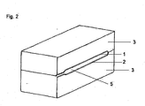
- the injection molding tool is closed by moving the two tool halves 3 together (FIG. 2). Between the films, a cavity 5 is formed, which is filled by injecting a thermoplastic PC (polycarbonate). The thickness of the plate thus produced is 5mm.
- a thermoplastic PC polycarbonate
- the tool For the metal angle to be inserted in the next work step, the tool must receive a new cavity.
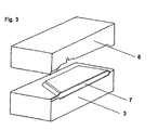
- the cavity to be changed is located on a so-called turning plate, which rotates the old cavity by rotation about 180 degrees about its vertical axis and positions the new cavity 6 (FIG. 3).
- the previously injection-molded plate 7 remains in the nozzle-side half of the tool 3.
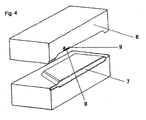
- a handling system now positions a metallic angle 8 in the new cavity 6 in FIG. 4.
- the cavity must be designed such that a gap 9 of 2.5 mm height is present between the wall of the cavity 6 and the metal insert.
- thermoplastic component 10 is injected into the gap 9.
- the material used for this purpose is a PC / PET blend.
- the second thermoplastic component 10 is visible. It completely encloses the metal insert 8 and forms a strongly adhering connection with the injection-molded plate 7 underneath.
Landscapes
- Engineering & Computer Science (AREA)
- Manufacturing & Machinery (AREA)
- Mechanical Engineering (AREA)
- Injection Moulding Of Plastics Or The Like (AREA)
- Moulds For Moulding Plastics Or The Like (AREA)
Abstract
(a) Einbringen einer ersten (1) und einer zweiten Folie (2) aus Kunststoff in eine erste Kavität eines Spritzgießwerkzeugs (3),
(b) Einspritzen eines ersten thermoplastischen Kunststoffs in den Hohlraum (5) zwischen der ersten (1) und der zweiten Folie (2),
(c) Entformen des gemäß Schritt (b) hergestellten ersten Formteils (7) und Einbringen des ersten Formteils in eine zweite Kavität (6) des Spritzgießwerkzeugs,
(d) Einspritzen eines zweiten thermoplastischen Kunststoffs in die zweite Kavität (6,3).
Description
- Die Erfindung betrifft ein Verfahren zur Herstellung eines Verbundbauteils mittels Spritzgießen oder Spritzprägen.
- Optische Bauteile, z.B. Scheiben im Automobilbau, werden vorwiegend aus Glas hergestellt, da sie sehr gute Oberflächeneigenschaften, z.B. eine hohe Kratzfestigkeit, aufweisen. Diese Bauteile sind mit hohen Materialkosten verbunden und weisen ein geringes Integrationspotential auf. Dies bedeutet, dass die Bauteile nur mit erheblichem Aufwand mit anderen Formteilen verbunden werden können.
- Es ist aber auch bereits bekannt, optische Bauelemente aus transparentem thermoplastischem Kunststoff herzustellen. Diese sind nicht nur leichter und günstiger, sondern können auch erheblich einfacher mit weiteren Formteilen, wie Metall- oder Kunststoffteilen, verbunden werden. Die Kratzfestigkeit von Oberflächen aus transparentem thermoplastischem Kunststoff, muss jedoch durch eine Schutzschicht, z.B. aus Lack, erhöht werden.
- Derartige Verbundbauteile aus einem optischen Formteil aus transparentem thermoplastischem Kunststoff werden nach dem Stand der Technik in aufwändigen Verfahren mit mehreren separaten Schritten sowie in mehreren separaten Vorrichtungen hergestellt. Beispielsweise wird zunächst eine Scheibe aus transparentem Kunststoff mittels Spritzgießen hergestellt. Die Scheibe wird anschließend mit einem geeigneten Lack zur Erhöhung der Kratzfestigkeit der Scheibenoberflächen beschichtet. In einem dritten Schritt wird die beschichtete Scheibe in einem weiteren Spritzgießwerkzeug z.B. mit einer Dichtung versehen oder mit einem weiteren Formteil wie z.B. einer Führungsschiene verbunden.
- Aufgabe der vorliegenden Erfindung ist es, ein Verfahren zur Herstellung eines Verbundbauteils bereitzustellen, welches wenigstens aus einem beidseitig mit einer Folie beschichteten Kunststoff-Formteil und einem weiteren Formteil besteht. Das Verfahren soll möglichst einfach und in wenigen Schritten durchführbar sein.
- Die Erfindung beschreibt ein Verfahren zur Herstellung eines Verbundbauteils, umfassend die folgenden Schritte
- (a) Einbringen einer ersten und einer zweiten Folie aus transparentem Kunststoff in eine erste Kavität eines Spritzgießwerkzeugs, so dass die Folien auf gegenüberliegenden Seiten der Kavität gehalten werden und einen zwischen den Folien angeordneten Hohlraum bilden,
- (b) Einspritzen eines ersten thermoplastischen Kunststoffs in den Hohlraum zwischen der ersten und der zweiten Folie,
- (c) Entformen des gemäß Schritt (b) hergestellten ersten Formteils und Einbringen des ersten Formteils sowie gegebenenfalls wenigstens eines zweiten Formteils in eine zweite Kavität des selben oder eines zweiten Spritzgießwerkzeugs,
- (d) Einspritzen eines zweiten thermoplastischen Kunststoffs in die zweite Kavität gegebenenfalls zum Verbinden des ersten und des zweiten Formteils.
- Das erfindungsgemäße Verfahren wird in einem Spritzgießwerkzeug mit mindestens zwei Kavitäten durchgeführt. Im Rahmen der vorliegenden Erfindung werden vereinfachend die Begriffe Spritzgießen bzw. Spritzgießwerkzeug verwendet, die jedoch das Spritzprägen bzw. Spritzprägewerkzeug einschließen.
- In einer bevorzugten Ausführung wird das erste Formteil in der zweiten Kavität in Schritt (d) nur in seinem Randbereich mit dem zweiten thermoplastischen Kunststoff hinterspritzt, so dass ein transparenter Fensterbereich im ersten Formteil erhalten bleibt.
- Die erste und zweite Folie sind vorzugsweise transparent und bestehen bevorzugt aus Polycarbonat (PC), Polymethylmethacrylat (PMMA) oder einem Polycarbonat-Polymethylmethacrylat-Blend. Die beiden Folien können entweder aus dem gleichen oder aus unterschiedlichen Kunststoffen sein. Die Folien weisen vorzugsweise eine Dicke von 0,1 bis 1 mm auf.
- In einer bevorzugten Ausführungsform des Verfahrens werden die erste und die zweite Folie vor dem Einbringen in das Spritzgießwerkzeug gemäß Schritt (a) umgeformt, beschnitten, beschichtet und/oder bedruckt. Vorzugsweise werden die erste und zweite Folie mit einem Lack oder einer Schicht aus PMMA beschichtet. Insbesondere eignen sich Hardcoat-Lacke, wie z.B. Siloxan-Lacke oder UV-härtbare Lacke. Für das Beschichten von Folien sind Verfahren aus dem Stand der Technik bekannt. Das Beschichten der ersten und zweiten Folie mit einer Schicht aus PMMA kann beispielsweise mittels Coextrusion erfolgen. Lacke können beispielsweise mittels Sprühen aufgetragen werden. Je nach Art der Beschichtung können die Folien nach dem Beschichten nicht mehr umgeformt werden, sodass das Umformen vor dem Beschichten erfolgen muss. Das Umformen erfolgt beispielsweise mittels Tiefziehen. Die Folien können zusätzlich vor dem Beschichten und dem Tiefziehen mit Siebdruckfarben bedruckt werden.
- Die erste und zweite Folie werden gemäß Schritt (a) in eine erste Kavität eines Spritzgießwerkzeugs eingebracht. Sie werden derart eingebracht, dass sie in der Kavität auf Abstand gehalten werden. Das Fixieren der beiden Folien in der Kavität erfolgt in der nach dem Stand der Technik bekannten Weise, z.B. mechanisch, elektrostatisch oder mittels Vakuum.
- Die erste und zweite Folie können beispielsweise im Wesentlichen parallel zueinander angeordnet werden. Durch den Abstand zwischen der ersten und zweiten Folie bildet sich in der Kavität ein Hohlraum aus, in den im Schritt (b) ein erster thermoplastischer Kunststoff eingespritzt wird. Dadurch wird ein erstes Formteil gebildet, welches gemäß Schritt (c) entformt wird.
- Grundsätzlich kann die Form des ersten Formteils beliebig sein. Zum Beispiel kann das erste Formteil scheibenförmig, plattenförmig oder topfförmig sein, wobei die Scheibe oder Platte beispielsweise eben, gewölbt oder gekrümmt sein kann. Das erste Formteil kann über seine gesamte Fläche die gleiche Dicke oder aber in verschiedenen Bereichen unterschiedliche Dicken aufweisen. Für die Herstellung eines scheibenförmigen Formteils kann die Dicke 3 bis 6 mm betragen.
- Bevorzugt handelt es sich bei dem ersten thermoplastischen Kunststoff um einen transparenten Kunststoff. Der erste thermoplastische Kunststoff ist besonders bevorzugt ausgewählt aus der Reihe Polycarbonat (PC), Polymethylmethacrylat (PMMA), transparentes Polyamid (PA), Cyclo-Olefin-Copolymner (COC) oder einer Mischung von zwei oder mehr dieser Polymere. Es kann jedoch für ein nicht transparentes erstes Formteil auch jeder andere thermoplastische Kunststoff verwendet werden, der sich für das Spritzgießen oder Spritzprägen eignet.
- Nach dem Entformen wird das erste Formteil in eine zweite Kavität des Spritzgießwerkzeugs eingebracht (Schritt (c)). Das Umsetzen des ersten Formteils kann nach bekannten Verfahren, wie sie beispielsweise beim Mehrfarbenspritzgießen angewendet werden, erfolgen. Typische Verfahren sind einerseits das Umsetzen mit Drehteller, Wendeplatte, Schiebekavität oder Indexplatte oder vergleichbare Verfahren, bei denen das erste Formteil auf dem Kern verbleibt. Andererseits sind aus dem Stand der Technik Verfahren zum Umsetzen eines Formteils bekannt, bei denen das Formteil, z.B. mit Hilfe eines Handhabungssystems, aus einer Kavität entnommen und in eine andere Kavität eingelegt wird.
- Außerdem wird bevorzugt wenigstens ein zweites Formteil in die zweite Kavität eingebracht. Das zweite Formteil kann ein beliebiges Formteil aus Kunststoff und/oder Metall sein. Ist das erste Formteil eine transparente Scheibe, die z.B. im Automobilbau eingesetzt wird, kann das zweite Formteil eine Führungsschiene aus Stahl, Aluminium, Polyamid, insbesondere gefülltes Polyamid, oder Polycarbonat sein.
- Zum Verbinden des ersten und des zweiten Formteils wird in die zweite Kavität des Spritzgießwerkzeugs ein zweiter thermoplastischer Kunststoff eingespritzt. Der zweite thermoplastische Kunststoff kann z.B. Thermoplastisches Polyurethan (TPU), Thermoplastisches Polyethylen (TPE), PC-Blends, PVC, oder einer der oben genannten transparenten Kunststoffe sowie eine Mischung von diesen Kunststoffen sein.
- Gegenstand der Erfindung sind auch Kunststofffenster erhalten nach dem erfindungsgemäßen Verfahren sowie deren Verwendung für den Fahrzeugbau, z.B. von Kraftfahrzeugen, Schiffen oder Flugzeugen oder für Haushaltsgeräte.
- Die Erfindung wird nachstehend anhand der Figuren beispielhaft näher erläutert.
- Es zeigen
- Fig. 1
- das geöffnete Formwerkzeug
- Fig. 2
- das geschlossene Formwerkzeug mit Folien
- Fig. 3
- die Bereitstellung einer zweiten Formwerkzeughälfte
- Fig. 4
- das Einbringen eines Winkels 8
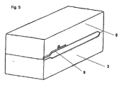
- Fig. 5
- das Schließen der Werkzeughälften
- Fig. 6
- die wieder geöffneten Werkzeughälften und den angespritzten zweiten Kunststoff
- Das nachfolgende Beispiel beschreibt die Herstellung eines teilweise transparenten Bauteils, welches mit Hilfe eines Metalleinlegers versteift wird und durch außen liegende
- Folien vor Verkratzen der Oberfläche geschützt wird. Der Metalleinleger kann neben einer versteifenden Funktion auch als lokale Verstärkung für Verschraubung von Anbauteilen dienen.
- In einem ersten Arbeitsschritt wird eine Folie auf Basis von PC (Polycarbonat) mit einer Schicht PMMA (Polymethylmethacrylat) coextrudiert. Zum Einlegen der Folie in eine dreidimensional gestaltete Werkzeugkavität kann diese zunächst in einem Tiefziehprozess umgeformt und beschnitten oder direkt durch den Spritzgießprozess in die entsprechende Form gebracht werden.
- Die erste 1 und zweite 2 coextrudierte Folie wird gemäß Fig. 1 in die geöffneten Hälften 3 des Spritzgusswerkzeugs eingebracht. Hierbei handelt es sich um nicht vorgeformte ebene Folien. Durch kleine Löcher 4 im Werkzeug wird ein Vakuum erzeugt, das die Folien in die Kavität des Werkzeugs presst und positioniert.
- Das Spritzgusswerkzeug wird durch Zusammenfahren der beiden Werkzeughälften 3 geschlossen (Fig.2). Zwischen den Folien entsteht ein Hohlraum 5, der durch Einspritzen eines thermoplastischen Kunststoffs PC (Polycarbonat) gefüllt wird. Die Dicke der so hergestellten Platte beträgt 5mm.
- Für den im nächsten Arbeitsschritt einzulegenden Metallwinkel muss das Werkzeug eine neue Kavität erhalten. Die zu wechselnde Kavität befindet sich auf einer so genannten Wendeplatte, die durch Rotation um 180 Grad um ihre Hochachse die alte Kavität wegdreht und die neue Kavität 6 positioniert (Fig.3). Die zuvor spritzgegossene Platte 7 verbleibt in der düsenseitigen Hälfte des Werkzeugs 3.
- Ein Handhabungssystem positioniert in Fig.4 nun einen metallischen Winkel 8 in die neuen Kavität 6. Die Kavität muss so gestaltet sein, dass zwischen der Wand der Kavität 6 und dem Metalleinleger ein Spalt 9 von 2,5 mm Höhe vorhanden ist.
- Die beiden Werkzeughälften 3 und 6 werden erneut zugefahren (Fig. 5). Eine zweite thermoplastische Komponente wird in den Spalt 9 eingespritzt. Als Werkstoff wird hierfür ein PC/PET Blend verwendet. In Fig. 6 ist die zweite thermoplastische Komponente 10 sichtbar. Sie umschließt den Metalleinleger 8 vollständig und geht eine stark haftende Verbindung mit der darunter liegenden spritzgegossenen Platte 7 ein.
Claims (11)
- Verfahren zur Herstellung eines Verbundbauteils, umfassend die folgenden Schritte(a) Einbringen einer ersten und einer zweiten Folie aus transparentem Kunststoff in eine erste Kavität eines Spritzgießwerkzeugs, so dass die beiden Folien auf gegenüberliegenden Seiten der Kavität gehalten werden und einem zwischen den Folien angeordneten Hohlraum bilden,(b) Einspritzen eines ersten thermoplastischen Kunststoffs in den Hohlraum zwischen der ersten und der zweiten Folie,(c) Entformen des gemäß Schritt (b) hergestellten ersten Formteils und Einbringen des ersten Formteils in eine zweite Kavität desselben oder eines zweiten Spritzgießwerkzeugs,(d) Einspritzen eines zweiten thermoplastischen Kunststoffs in die zweite Kavität.
- Verfahren nach Anspruch 1, dadurch gekennzeichnet, dass mit dem ersten Formteil im Schritt (c) wenigstens ein zweites Formteil in die zweite Kavität eingelegt und in Schritt (d) mit dem ersten Formteil durch den zweiten thermoplastischen Kunststoff verbunden wird.
- Verfahren nach einem der Ansprüche 1 oder 2, dadurch gekennzeichnet, dass das erste Formteil in der zweiten Kavität in Schritt (d) mit dem zweiten thermoplastischen Kunststoff in seinem Randbereich unter Erhalt eines transparenten Fensters im ersten Formteil umspritzt wird.
- Verfahren nach einem der Ansprüche 1 bis 3, dadurch gekennzeichnet, dass die erste und die zweite Folie vor dem Einbringen in das Spritzgießwerkzeug gemäß Schritt (a) verformt, beschnitten, beschichtet und/oder bedruckt werden.
- Verfahren nach einem der Ansprüche 1 bis 4, dadurch gekennzeichnet, dass die erste und zweite Folie auf mindestens einem der Werkstoffe Polycarbonat (PC), Polymethylmethacrylat (PMMA) oder einem Polycarbonat-Polymethylmethacrylat-Blend basieren.
- Verfahren nach einem der Ansprüche 1 bis 5, dadurch gekennzeichnet, dass der erste thermoplastische Kunststoff transparent ist.
- Verfahren nach Anspruch 6, dadurch gekennzeichnet, dass der erste thermoplastische Kunststoff ausgewählt ist aus der Reihe: Polycarbonat (PC), Polymethylmethacrylat (PMMA), transparentes Polyamid (PA) oder Cyclo-Olefin-Copolymer (COC) oder einer Mischung dieser Polymere.
- Verfahren nach einem der Ansprüche 1 bis 7, dadurch gekennzeichnet, dass das zweite Formteil aus Kunststoff und/oder Metall besteht.
- Verfahren nach einem der Ansprüche 1 bis 8, dadurch gekennzeichnet, dass der zweite thermoplastische Kunststoff ausgewählt ist aus der Reihe: Thermoplastisches Polyurethan (TPU), Thermoplastisches Polyethylen (TPE), Polycarbonat (PC), PC-Blends, PMMA, transparentes Polyamid (PA), Cyclo-Olefin-Copolymer, PVC oder einer Mischung dieser Polymere.
- Kunststofffenster hergestellt nach einem der Ansprüche 1 bis 9.
- Verwendung des Fensters nach Anspruch 10 für Haushaltsgeräte oder im Fahrzeugbau, insbesondere für Kraftfahrzeuge oder im Schiffs- oder Flugzeugbau.
Applications Claiming Priority (1)
| Application Number | Priority Date | Filing Date | Title |
|---|---|---|---|
| DE10532664 | 2005-07-13 |
Publications (1)
| Publication Number | Publication Date |
|---|---|
| EP1743756A1 true EP1743756A1 (de) | 2007-01-17 |
Family
ID=36829794
Family Applications (1)
| Application Number | Title | Priority Date | Filing Date |
|---|---|---|---|
| EP06013570A Withdrawn EP1743756A1 (de) | 2005-07-13 | 2006-06-30 | Verfahren zur Herstellung eines Verbundbauteils |
Country Status (1)
| Country | Link |
|---|---|
| EP (1) | EP1743756A1 (de) |
Cited By (10)
| Publication number | Priority date | Publication date | Assignee | Title |
|---|---|---|---|---|
| WO2009103446A1 (de) * | 2008-02-23 | 2009-08-27 | Bayer Materialscience Ag | Asymmetrischer mehrschichtverbund |
| WO2010091741A1 (en) * | 2009-02-16 | 2010-08-19 | Gaming Partners International | Method of producing a gaming chip |
| WO2014176399A3 (en) * | 2013-04-26 | 2015-01-29 | United States Gypsum Company | Double fabric faced injection molded fixture |
| WO2015091383A1 (de) * | 2013-12-18 | 2015-06-25 | Leonhard Kurz Stiftung & Co. Kg | Kunststoffformteil und verfahren zu dessen herstellung |
| WO2016008790A1 (de) * | 2014-07-17 | 2016-01-21 | Saint-Gobain Glass France | Verfahren zur herstellung eines kunststoff-fahrzeuganbauteils |
| US9307869B2 (en) | 2013-04-26 | 2016-04-12 | Mgnt Products Group Llc | Integrated bonding flange support disk for prefabricated shower tray |
| DE102016004030A1 (de) * | 2016-04-02 | 2017-10-05 | GM Global Technology Operations LLC (n. d. Ges. d. Staates Delaware) | Kunststoffscheibe mit Dekorschicht für eine Kraftfahrzeugkarosserie |
| DE102020101464A1 (de) | 2020-01-22 | 2021-07-22 | Preh Gmbh | Herstellungsverfahren für eine eine Gießharzschicht aufweisende Kunststoffverbundabdeckung sowie zugehörige Kunststoffverbundabdeckung |
| DE102020101458A1 (de) | 2020-01-22 | 2021-07-22 | Preh Gmbh | Herstellungsverfahren für eine Kunststoffverbundabdeckung sowie zugehörige Kunststoffverbundabdeckung |
| US12151413B2 (en) | 2019-08-08 | 2024-11-26 | Preh Gmbh | Plastic composite panel and associated production method |
Citations (5)
| Publication number | Priority date | Publication date | Assignee | Title |
|---|---|---|---|---|
| US4874654A (en) * | 1987-06-15 | 1989-10-17 | Nippon Sheet Glass Co., Ltd. | Vehicle window glass |
| EP0415716A1 (de) * | 1989-08-31 | 1991-03-06 | Hashimoto Forming Industry Co Ltd | Kunstharzfenster für Kraftfahrzeuge oder dgl. |
| JPH1024443A (ja) * | 1996-07-10 | 1998-01-27 | Honda Motor Co Ltd | 車両用風防部材の製造方法及び車両用風防部材の製造装置 |
| DE19927999A1 (de) * | 1998-06-19 | 1999-12-23 | Toyoda Automatic Loom Works | Kunstharz-Fensterscheibe sowie Verfahren zu ihrer Herstellung |
| DE10147537A1 (de) * | 2001-09-26 | 2003-04-17 | Freeglass Gmbh & Co Kg | Verfahren zum Herstellen einer Kunststoffscheibe mit einer Leitstruktur und Kunststoffscheibe mit eingebetteten Drähten |
-
2006
- 2006-06-30 EP EP06013570A patent/EP1743756A1/de not_active Withdrawn
Patent Citations (5)
| Publication number | Priority date | Publication date | Assignee | Title |
|---|---|---|---|---|
| US4874654A (en) * | 1987-06-15 | 1989-10-17 | Nippon Sheet Glass Co., Ltd. | Vehicle window glass |
| EP0415716A1 (de) * | 1989-08-31 | 1991-03-06 | Hashimoto Forming Industry Co Ltd | Kunstharzfenster für Kraftfahrzeuge oder dgl. |
| JPH1024443A (ja) * | 1996-07-10 | 1998-01-27 | Honda Motor Co Ltd | 車両用風防部材の製造方法及び車両用風防部材の製造装置 |
| DE19927999A1 (de) * | 1998-06-19 | 1999-12-23 | Toyoda Automatic Loom Works | Kunstharz-Fensterscheibe sowie Verfahren zu ihrer Herstellung |
| DE10147537A1 (de) * | 2001-09-26 | 2003-04-17 | Freeglass Gmbh & Co Kg | Verfahren zum Herstellen einer Kunststoffscheibe mit einer Leitstruktur und Kunststoffscheibe mit eingebetteten Drähten |
Non-Patent Citations (2)
| Title |
|---|
| HOPMANN, C; GÖBEL, S. FORSTER, J.: "Automobilscheiben aus Kunststoff", KUNSTSTOFFE, no. 2/05, February 2005 (2005-02-01), pages 22 - 27, XP002396333 * |
| PATENT ABSTRACTS OF JAPAN vol. 1998, no. 05 30 April 1998 (1998-04-30) * |
Cited By (21)
| Publication number | Priority date | Publication date | Assignee | Title |
|---|---|---|---|---|
| CN101952118A (zh) * | 2008-02-23 | 2011-01-19 | 拜尔材料科学股份公司 | 不对称多层复合材料 |
| CN101952118B (zh) * | 2008-02-23 | 2014-12-17 | 拜尔材料科学股份公司 | 不对称多层复合材料 |
| WO2009103446A1 (de) * | 2008-02-23 | 2009-08-27 | Bayer Materialscience Ag | Asymmetrischer mehrschichtverbund |
| WO2010091741A1 (en) * | 2009-02-16 | 2010-08-19 | Gaming Partners International | Method of producing a gaming chip |
| US9731441B2 (en) | 2013-04-26 | 2017-08-15 | MGNT Products Group, LLC | Double fabric faced injection molded fixture |
| WO2014176399A3 (en) * | 2013-04-26 | 2015-01-29 | United States Gypsum Company | Double fabric faced injection molded fixture |
| US9771713B2 (en) | 2013-04-26 | 2017-09-26 | Mgnt Products Group Llc | Integrated bonding flange support disk for prefabricated shower tray |
| US9307869B2 (en) | 2013-04-26 | 2016-04-12 | Mgnt Products Group Llc | Integrated bonding flange support disk for prefabricated shower tray |
| WO2015091383A1 (de) * | 2013-12-18 | 2015-06-25 | Leonhard Kurz Stiftung & Co. Kg | Kunststoffformteil und verfahren zu dessen herstellung |
| US10377067B2 (en) | 2013-12-18 | 2019-08-13 | Leonhard Kurz Stiftung & Co. Kg | Plastic moulded part and method for the production thereof |
| US10875222B2 (en) | 2013-12-18 | 2020-12-29 | Leonhard Kurz Stiftung & Co. Kg | Plastic moulded part and method for the production thereof |
| KR20170018043A (ko) * | 2014-07-17 | 2017-02-15 | 쌩-고벵 글래스 프랑스 | 플라스틱 차량 부재의 제조 방법 |
| WO2016008790A1 (de) * | 2014-07-17 | 2016-01-21 | Saint-Gobain Glass France | Verfahren zur herstellung eines kunststoff-fahrzeuganbauteils |
| US10166706B2 (en) | 2014-07-17 | 2019-01-01 | Saint-Gobain Glass France | Method for producing a plastic vehicle part |
| KR101994004B1 (ko) | 2014-07-17 | 2019-06-27 | 쌩-고벵 글래스 프랑스 | 플라스틱 차량 부재의 제조 방법 |
| EA033709B1 (ru) * | 2014-07-17 | 2019-11-19 | Saint Gobain | Способ изготовления пластмассовой автомобильной детали |
| US10603826B2 (en) | 2014-07-17 | 2020-03-31 | Saint-Gobain Glass France | Method for producing a plastic vehicle part |
| DE102016004030A1 (de) * | 2016-04-02 | 2017-10-05 | GM Global Technology Operations LLC (n. d. Ges. d. Staates Delaware) | Kunststoffscheibe mit Dekorschicht für eine Kraftfahrzeugkarosserie |
| US12151413B2 (en) | 2019-08-08 | 2024-11-26 | Preh Gmbh | Plastic composite panel and associated production method |
| DE102020101464A1 (de) | 2020-01-22 | 2021-07-22 | Preh Gmbh | Herstellungsverfahren für eine eine Gießharzschicht aufweisende Kunststoffverbundabdeckung sowie zugehörige Kunststoffverbundabdeckung |
| DE102020101458A1 (de) | 2020-01-22 | 2021-07-22 | Preh Gmbh | Herstellungsverfahren für eine Kunststoffverbundabdeckung sowie zugehörige Kunststoffverbundabdeckung |
Similar Documents
| Publication | Publication Date | Title |
|---|---|---|
| DE102013113230A1 (de) | Verfahren zur Herstellung eines Außenverkleidungsteils für ein bewegbares Karosserieteil sowie ein entsprechendes Außenverkleidungsteil | |
| DE102004062477A1 (de) | Verfahren zur Herstellung eines Verbundformteiles aus Kunststoff und dessen Verwendung | |
| DE102005032664A1 (de) | Verfahren zur Herstellung eines Verbundbauteils | |
| DE102009032815A1 (de) | Lackfolienprodukt, ein mit dem Lackfolienprodukt beschichtetes Trägerelement mit eingebettetem Objekt und Herstellungsverfahren | |
| WO2006066719A2 (de) | Kunststoff-formteil und verfahren zu dessen herstellung | |
| EP1743756A1 (de) | Verfahren zur Herstellung eines Verbundbauteils | |
| DE102008022224A1 (de) | Verfahren zum Herstellen eines Kunststoffformteils mit einer Lackbeschichtung | |
| DE102005039124B4 (de) | Verfahren zur Herstellung eines zweischichtigen Verbundteils | |
| DE102014011135A1 (de) | Verfahren und Vorrichtung zur Herstellung eines Dekorteils | |
| DE102012014082B4 (de) | Dekorformteil und Verfahren zu dessen Herstellung | |
| DE102015211086A1 (de) | Kunststoffelement, Herstellvorrichtung und Verfahren zum Herstellen des Kunststoffelements | |
| DE102009017698A1 (de) | Fahrzeug-Folienbauteil und Verfahren zu dessen Herstellung | |
| DE202014101678U1 (de) | Dekorteil für einen Fahrzeuginnenraum und Vorrichtung zum Herstellen des Dekorteils | |
| EP1725443B1 (de) | Fahrzeug folienbauteil und verfahren zu dessen herstellung | |
| WO2018172194A1 (de) | Verfahren zur herstellung eines kunststoff-fahrzeuganbauteils | |
| EP3285983B1 (de) | Verfahren zum herstellen eines mehrteiligen kunststoffbauteils sowie mehrteiliges kunststoffbauteil | |
| DE102012023066A1 (de) | Foliendekoriertes Kunststoff-Formteil sowie Verfahren zur Herstellung eines solchen Formteiles | |
| DE102005024776B4 (de) | Verfahren zum Herstellen eines Kunststoffverbundteils | |
| DE102005028355A1 (de) | Innenverkleidungsteil für Kraftfahrzeuge sowie Verfahren zur Herstellung eines Innenverkleidungsteils | |
| WO2012126907A1 (de) | Verfahren zur herstellung eines verbundbauteils | |
| DE102005061451B4 (de) | Thermoplastisches Bauteil mit einer farbigen Dekorschicht und Verfahren zur Herstellung | |
| DE102018212152A1 (de) | Dekorteil | |
| EP3793828B1 (de) | Kunststoffverbundblende sowie zugehöriges herstellungsverfahren | |
| DE102015218142A1 (de) | Verfahren zur Herstellung eines Verbundbauteils | |
| DE10333898B3 (de) | Verfahren zur Herstellung von hinterspritzten Formteilen mit unterschiedlichen Wanddicken und Größen |
Legal Events
| Date | Code | Title | Description |
|---|---|---|---|
| PUAI | Public reference made under article 153(3) epc to a published international application that has entered the european phase |
Free format text: ORIGINAL CODE: 0009012 |
|
| AK | Designated contracting states |
Kind code of ref document: A1 Designated state(s): AT BE BG CH CY CZ DE DK EE ES FI FR GB GR HU IE IS IT LI LT LU LV MC NL PL PT RO SE SI SK TR |
|
| AX | Request for extension of the european patent |
Extension state: AL BA HR MK YU |
|
| 17P | Request for examination filed |
Effective date: 20070717 |
|
| 17Q | First examination report despatched |
Effective date: 20070820 |
|
| AKX | Designation fees paid |
Designated state(s): AT DE FR GB IT |
|
| STAA | Information on the status of an ep patent application or granted ep patent |
Free format text: STATUS: THE APPLICATION IS DEEMED TO BE WITHDRAWN |
|
| 18D | Application deemed to be withdrawn |
Effective date: 20080103 |