EP1743544B1 - Electrical apparatus system - Google Patents
Electrical apparatus system Download PDFInfo
- Publication number
- EP1743544B1 EP1743544B1 EP20060014346 EP06014346A EP1743544B1 EP 1743544 B1 EP1743544 B1 EP 1743544B1 EP 20060014346 EP20060014346 EP 20060014346 EP 06014346 A EP06014346 A EP 06014346A EP 1743544 B1 EP1743544 B1 EP 1743544B1
- Authority
- EP
- European Patent Office
- Prior art keywords
- electric power
- electrical apparatus
- depilator
- cleaning
- supplied
- Prior art date
- Legal status (The legal status is an assumption and is not a legal conclusion. Google has not performed a legal analysis and makes no representation as to the accuracy of the status listed.)
- Not-in-force
Links
Images


Classifications
-
- A—HUMAN NECESSITIES
- A45—HAND OR TRAVELLING ARTICLES
- A45D—HAIRDRESSING OR SHAVING EQUIPMENT; EQUIPMENT FOR COSMETICS OR COSMETIC TREATMENTS, e.g. FOR MANICURING OR PEDICURING
- A45D26/00—Hair-singeing apparatus; Apparatus for removing superfluous hair, e.g. tweezers
-
- A—HUMAN NECESSITIES
- A45—HAND OR TRAVELLING ARTICLES
- A45D—HAIRDRESSING OR SHAVING EQUIPMENT; EQUIPMENT FOR COSMETICS OR COSMETIC TREATMENTS, e.g. FOR MANICURING OR PEDICURING
- A45D20/00—Hair drying devices; Accessories therefor
- A45D20/22—Helmets with hot air supply or ventilating means, e.g. electrically heated air current
- A45D20/30—Electric circuitry specially adapted for hair drying devices
-
- H—ELECTRICITY
- H02—GENERATION; CONVERSION OR DISTRIBUTION OF ELECTRIC POWER
- H02J—CIRCUIT ARRANGEMENTS OR SYSTEMS FOR SUPPLYING OR DISTRIBUTING ELECTRIC POWER; SYSTEMS FOR STORING ELECTRIC ENERGY
- H02J7/00—Circuit arrangements for charging or depolarising batteries or for supplying loads from batteries
- H02J7/0013—Circuit arrangements for charging or depolarising batteries or for supplying loads from batteries acting upon several batteries simultaneously or sequentially
-
- H—ELECTRICITY
- H02—GENERATION; CONVERSION OR DISTRIBUTION OF ELECTRIC POWER
- H02J—CIRCUIT ARRANGEMENTS OR SYSTEMS FOR SUPPLYING OR DISTRIBUTING ELECTRIC POWER; SYSTEMS FOR STORING ELECTRIC ENERGY
- H02J7/00—Circuit arrangements for charging or depolarising batteries or for supplying loads from batteries
- H02J7/0063—Circuit arrangements for charging or depolarising batteries or for supplying loads from batteries with circuits adapted for supplying loads from the battery
Definitions
- the present invention relates to an electrical apparatus system including a power generator, a first electrical apparatus and a second electrical apparatus used together with the first electrical apparatus.
- Japanese Patent Application Laid-open No. 2004-243113 discloses an electrical apparatus system in which a depilator that depilates body hair is used as the first electrical apparatus, a cleaning apparatus that cleans the depilator is used as the second electrical apparatus, and an AC adapter is used as a power generator that supplies electricity to these electrical apparatuses.
- a depilator 1 is the first electrical apparatus.
- the depilator 1 includes a control circuit 51 that generally controls the depilator 1, a battery (secondary battery) 52, a side surface terminal 53 that is connected to a cleaning apparatus 2, a charging circuit 54 that charges the battery 52, and a cutting unit 55 that cuts body hair.
- the cutting unit 55 includes a blade for cutting the body hair, and a motor for rotating the blade.
- the cleaning apparatus 2 as the second electrical apparatus, includes a control circuit 61 that controls the entire cleaning apparatus 2, a connection terminal 62 that is connected to the side surface terminal 53 provided in the depilator 1, a cleaning unit 63 that cleans the cutting unit 55, a tightly closed container (not shown) in which cleaning liquid is accommodated, and a pump 64 that supplies the cleaning liquid in the container to the cleaning unit 63 by pressurizing the tightly closed container.
- the pump 64 pressurizes the cleaning liquid in the cleaningunit 63 after cleaning to send back the same into the container.
- the cleaning apparatus 2 also includes an air valve 65 for releasing the air-tight state in the container when the cleaning of the depilator 1 using the cleaning liquid is completed and when the cleaning liquid is collected by the pump 64, a fan apparatus 66 that sends air into the cutting unit 55 to dry the same, and a display circuit 68 for displaying states of the depilator 1 and the cleaning apparatus 2 such as the charging state, the cleaning state and the like.
- the control circuit 51 of the depilator 1 controls the depilator 1 such that the cutting unit 55 is driven by electric power supplied from an external power supply through an AC adapter or electric power supplied from the battery 52. Control is performed such that the cutting unit 55 of the depilator 1 is driven according to a signal sent from the cleaning apparatus 2 through the connection terminal 62 of the cleaning apparatus 2 and the side surface terminal 53 of the depilator 1.
- the charging circuit 54 charges the battery 52 by electric power supplied from the external power supply through the AC adapter or electric power supplied from the cleaning apparatus 2 through the connection terminal 62 of the cleaning apparatus 2 and the side surface terminal 53 of the depilator 1.
- the control circuit 61 of the cleaning apparatus 2 controls operations such as a cleaning operation and a charging operation.
- the control circuit 61 also controls the sending operations of the control signal and the electric power to the depilator 1 through the connection terminal 62 of the cleaning apparatus 2 and the side surface terminal 53 of the depilator 1.
- the display circuit 68 includes a display element such as a light-emitting diode, and a drive circuit. The display circuit 68 turns the display element ON or OFF according to a signal from the control circuit 61, the display circuit 68 display the operation state (charging, cleaning or the like) of the depilator 1 and the cleaning apparatus 2.
- the power generator (not shown) is an AC adapter that converts AC electric power input from the external power supply into DC electric power of level necessary for operating the depilator 1 and the cleaning apparatus 2.
- DC electric power is supplied to the depilator 1 and the cleaning apparatus 2 by connecting the external power supply and the depilator 1 or the cleaning apparatus 2 to each other.
- the AC adapter is connected to the depilator 1, and the cutting unit 55 is driven by electric power supplied from the external power supply through the AC adapter.
- the AC adapter is not connected, and the cutting unit 55 is driven by electric power supplied from the battery 52 incorporated in the depilator 1, thereby removing the body hair.
- the external power supply and the cleaning apparatus 2 are connected to each other through the AC adapter, the depilator 1 is reclined against along an inclined portion 67 that rises upward on the one side of the cleaning unit 63 of the cleaning apparatus 2 (right side in Fig.
- the cutting unit 55 is disposed in the cleaning unit 63. If the side surface terminal 53 comes into contact with the connection terminal 62, the contact of the side surface terminal 53 with respect to the connection terminal 62 is detected by any detector, and control is performed such that the cleaning operation is started by the control circuit 61 of the cleaning apparatus 2. Simultaneously, a control signal and electric power are supplied from the cleaning apparatus 2 through the connection terminal 62 and the side surface terminal 53. The control signal sent from the cleaning apparatus 2 through the connection terminal 62 and the side surface terminal 53 is input to the control circuit 51 of the depilator 1 to drive the cutting unit 55. The battery 52 is charged by the electric power supplied from the cleaning apparatus 2 through the connection terminal 62 and the side surface terminal 53.
- connection terminal 62 and the side surface terminal 53 By sending the control signal and electric power from the cleaning apparatus 2 through the connection terminal 62 and the side surface terminal 53 in this manner, the operation of the cleaning apparatus 2 connected to the external power supply through the AC adapter is controlled, and control of the operation of the depilator 1 and the charging operation can be carried out.
- DC electric power is supplied to the depilator 1 and the cleaning apparatus 2 using the AC adapter, but when the electrical apparatus system has only one AC adapter, in order to clean the depilator 1 after the AC adapter is connected to the depilator 1 and is used, it is necessary to detach the AC adapter from the depilator 1 and is attached to the cleaning apparatus 2, and there is a problem that it is troublesome to switch the AC adapter.
- the present invention has been achieved in view of the above problem, and it is an obj ect of the invention to provide an electrical apparatus system in which when an external power supply is connected to one of two electrical apparatuses, electric power can be supplied to the other electrical apparatus to which the external power supply is not connected.
- the present invention provides an electrical apparatus system including a power generator that produces desired output electric power from input electric power from an external power supply, a first electrical apparatus having a first load to which electric power is supplied from the power generator, and a second electrical apparatus having a second load to which electric power is supplied from the power generator, the second electrical apparatus being used in combination with the first electrical apparatus, wherein the first electrical apparatus includes a first electric power transmitting unit configured to supply the electric power produced by the power generator to the second electrical apparatus and to supply the electric power supplied from the second electrical apparatus to the first load, the second electrical apparatus includes a second electric power transmitting unit configured to supply electric power produced by the power generator to the first electrical apparatus and to supply for supplying electric power supplied from the first electrical apparatus to the second load.
- the electric power when electric power produced by the power generator is to be supplied to the first electrical apparatus, the electric power can be supplied to the second electrical apparatus through the first electric power transmitting unit, and also when electric power produced by the power generator is to be supplied to the second electrical apparatus, electric power can be supplied to the first electrical apparatus through the second electric power transmitting unit. Therefore, it is possible to supply electric power to both the electrical apparatuses only by connecting the external power supply to one of the electrical apparatuses.
- the first electrical apparatus can include a secondary battery that supplies electric power to the first load, and a chargingunit that charges the secondary battery by the electric power produced by the power generator.
- the electrical apparatus system can be utilized without connecting the first electrical apparatus and the external power supply, and the degree of convenience is enhanced.
- the first electric power transmitting unit can be configured to supply electric power to the second load by the secondary battery.
- the second electrical apparatus can be connected to the external power supply, and the degree of convenience is enhanced.
- the first electrical apparatus can include a constant-voltage circuit that stabilizes battery voltage of the secondary battery to a predetermined constant value.
- the first electrical apparatus can include a constant-voltage circuit control unit that performs control such that the constant-voltage circuit is stopped when a predetermined operation time is elapsed after the time when the constant-voltage circuit starts an operation.
- a depilator 1 that is a first electrical apparatus and a cleaning apparatus 2 that is a second electrical apparatus of the present embodiment are the same as those of the conventional depilator 1 and cleaning apparatus 2. Therefore, illustration and explanation of the structures and operations which are not subject matter of the present invention will be omitted.
- the first electrical apparatus and the second electrical apparatus are not limited to the depilator 1 and the cleaning apparatus 2, and the technical idea of the invention can also be applied to other electrical apparatus systems having electrical apparatuses rather than the depilator 1 and the cleaning apparatus 2.
- the electrical apparatus system of the present embodiment includes the depilator 1 as the first electrical apparatus that depilates body hair, and the cleaning apparatus 2 as the second electrical apparatus that cleans the depilator 1, and an AC adapter 3 that supplies DC electric power to the depilator 1 or the cleaning apparatus 2.
- the depilator 1 includes a cutting unit 11 as a first load to which electric power is supplied from the AC adapter 3.
- the depilator 1 also includes a back surface terminal 12 that is a first electric power transmitting unit.
- the back surface terminal 12 has a function for supplying electric power generated by the AC adapter 3 to the cleaning apparatus 2, and a function for supplying the electric power supplied from the cleaning apparatus 2 to the cutting unit 11.
- the depilator 1 includes a secondary battery 13 and a charging circuit 14 as a charging unit for charging the secondary battery 13.
- the secondary battery 13 can be charged through the charging circuit 14 by the electric power supplied from the AC adapter 3 or electric power supplied from the connection terminal 22.
- the cleaning apparatus 2 includes a cleaning unit 24 in which the cutting unit 11 is cleaned, and a cleaning operation unit 21 as a second load to which electric power is supplied from the AC adapter.
- the cleaning operation unit 21 includes a pump, an air valve and a fan apparatus.
- the cleaning apparatus 2 also includes a connection terminal 22 as a second electric power transmitting unit.
- the connection terminal 22 has a function for supplying electric power generated by the AC adapter 3 to the depilator 1, and a function for supplying the electric power supplied from the depilator 1 to the cleaning operation unit 21.
- the AC adapter 3 includes a power supply plug 30 connected to the external power supply, a rectifier circuit 31 that rectifies ACvoltage supplied from the external power supply, a switching converter 32 that converts the rectified voltage into a predetermined voltage value, and a device plug 33 connected to the input unit 20 that receives electric power from the external power supply.
- the device plug 33 is provided in the input unit 10 or the cleaning apparatus 2 that is provided in the depilator 1 and that receives electric power from the external power supply.
- the external power supply and the depilator 1 or the cleaning apparatus 2 are connected to each other through the AC adapter 3.
- the AC electric power supplied from the external power supply is rectified by the rectifier circuit 31, and the rectified electric power is converted into high frequency by the switching circuit of the switching converter 32.
- the frequency is lowered by the transformer to a voltage value that is necessary for an operation of the depilator 1 or the cleaning apparatus 2.
- the voltage is again rectified and smoothened through a diode and a capacitor to produce DC electric power, and the same is supplied to the depilator 1 or the cleaning apparatus 2.
- the switching converter 32 is used as the converter circuit in this embodiment, the converter circuit is not limited to this, and other converter circuit can be constituted.
- the cutting unit 11 includes a blade for cutting the body hair, and a motor for rotating the blade.
- the cutting unit 11 is driven by electric power supplied from the AC adapter 3 or the connection terminal 22.
- the cleaning operation unit 21 includes a pump, an air valve and a fan apparatus. The cleaning operation unit 21 is driven by electric power supplied from the AC adapter 3 or the back surface terminal 12.
- the first electric power transmitting unit is a back surface terminal 12 provided on a back surface (surface opposed to the cleaning apparatus 2 in Fig. 2A ) of the depilator 1.
- the second electric power transmitting unit is a connection terminal 22 provided on a contact surface (surface opposed to the depilator 1 in Fig. 2A ) of the cleaning apparatus 2. If the back surface terminal 12 and the connection terminal 22 are brought into contact with each other, they are electrically connected to each other. With this configuration, electric power can be supplied from the depilator 1 to the cleaning apparatus 2, and electric power can be supplied from the cleaning apparatus 2 to the depilator 1.
- the depilating method of the body hair is the same as that according to the conventional example. That is, the AC adapter 3 is connected to the depilator 1, and the cutting unit 11 is driven by electric power supplied from the external power supply through the AC adapter 3. Alternatively, the AC adapter 3 may not be connected, and the cutting unit 11 may be driven by electric power supplied from the secondary battery 13.
- the depilator 1 is allowed to lean along an inclined portion 25 rising upward from one side (left side in Fig.
- a control circuit 23 provided in the cleaning apparatus 2 detects contact between the back surface terminal 12 and the connection terminal 22. Electric power produced by the AC adapter 3 is supplied to the cleaning operation unit 21 to drive the cleaning operation unit 21. Control is performed such that the cutting unit 11 of the depilator 1 is cleaned. At the same time, electric power is supplied to the cutting unit 11 of the depilator 1 through the connection terminal 22 and the back surface terminal 12 to drive the cutting unit 11.
- the secondary battery 13 is charged through the charging circuit 14.
- control is performed such that if the depilator 1 is set on the cleaning apparatus 2, the cleaning operation unit 21 and the cutting unit 11 are automatically driven and the secondary battery 13 is automatically charged.
- control can be performed such that the depilator 1 is disposed at a predetermined position of the cleaning apparatus 2, the back surface terminal 12 and the connection terminal 22 is brought into contact with each other and then, a switch (not shown) provided on the cleaning apparatus 2 is operated, and the cleaning operation unit 21 and the cutting unit 11 are driven and the secondary battery 13 can be charged.
- the depilator 1 When the AC adapter 3 is connected to the depilator 1 (see Fig. 2B ), the depilator 1 is allowed to lean along the inclined portion 25 such that the surface on which the side surface terminal 22 is provided and the surface on which the connection terminal 12 is provided are opposed to each other, and if the cutting unit 11 is disposed in the cleaning unit 24, a control circuit 15 of the depilator 1 detects the contact between the back surface terminal 12 and the connection terminal 22, electric power produced by the AC adapter 3 is supplied to the cutting unit 11 to drive the cutting unit 11, and the secondary battery 13 is charged through the charging circuit 14.
- control may not be performed such that if the depilator 1 is disposed in the cleaning apparatus 2, the cleaning operation unit 21 and the cutting unit 11 are driven and the secondary battery 13 is charged, but control may be performed such that if the switch (not shown) provided on the depilator 1 is operated, the cleaning operation unit 21 and the cutting unit 11 are driven and the secondary battery 13 is charged.
- the depilator 1 When the AC adapter 3 is not connected to any of the electrical apparatuses, the depilator 1 is allowed to lean along the inclined portion 25 such that the surface on which the side surface terminal 22 is provided and the surface on which the connection terminal 12 is provided are opposed to each other, and if the cutting unit 11 is disposed in the cleaning unit 24, a control circuit 15 of the depilator 1 detects the contact between the back surface terminal 12 and the connection terminal 22, electric power is supplied from the secondary battery 13 to the cutting unit 11 to drive the cutting unit 11. At the same time, electric power is supplied to the cleaning operation unit 21 of the cleaning apparatus 2 through the back surface terminal 12 and the connection terminal 22, the cleaning operation unit 21 is driven and the cutting unit 11 of the depilator 1 is cleaned. In this case also, like the case where the AC adapter 3 is connected to the depilator 1, control can be performed such that if the switch (not shown) provided on the depilator 1 is operated, the cleaning operation unit 21 and the cutting unit 11 are driven.
- both the depilator 1 and the cleaning apparatus 2 are provided with the electric power transmitting units.
- the AC adapter 3 no matter whether the AC adapter 3 is connected to depilator 1 or the cleaning apparatus 2, electric power can be supplied to both the depilator 1 and the cleaning apparatus 2. Therefore, if theACadapter3 is connected to one of the electrical apparatuses, it is unnecessary to switch the AC adapter 3, and the degree of convenience is enhanced. Even when the AC adapter 3 is not connected to any of the electrical apparatuses, the cleaning operation unit 21 and the cuttingunit 11 can be driven by the secondary battery 13 of the depilator 1, and the degree of convenience is enhanced.
- the electrical apparatus can includes a constant-voltage circuit 16 that increases the output voltage from the secondary battery 13, keeps the voltage constant and sends the same to the back surface terminal 12 (see Fig. 4 ).
- the constant-voltage circuit 16 includes a conventionally known step-up converter including an inductor, an FET and a diode.
- the constant-voltage circuit 16 makes the output voltage of the secondary battery 13 constant by PWM controlling the on duty ratio of the FET, and can supply stable electric power to the cleaning apparatus 2.
- the circuit structure of the constant-voltage circuit 16 is not limited to the above-described structure.
- the control circuit 15 can perform control such that when a predetermined operation time is elapsed from the time when the constant-voltage circuit 16 starts an operation, the constant-voltage circuit 16 is stopped. By limiting the operation time of the constant-voltage circuit 16, deterioration of battery lifetime caused by excessive charging of the secondary battery 13 can be prevented. In this case, the control circuit 15 is the constant-voltage control unit.
- the back surface terminal 12 and the connection terminal 22 are brought into contact with each other.
- the device plug 33 of the AC adapter 3 and the input unit 10 of the depilator 1 can include coils
- the input unit 20 of the cleaning apparatus 2 can include coils
- the electric power can be supplied in a non-contact manner utilizing electromagnetic induction between the coils (see Fig. 5 ).
- the device plug 33 of the AC adapter 3, the input unit 10 of the depilator 1, the input unit 20 of the cleaning apparatus 2, the back surface terminal 12 and the connection terminal 22 are respectively provided with coils.
- the device plug 33 and the input unit 10 of the depilator 1, or the input unit 20 of the cleaning apparatus 2 are electromagnetically connected with each other, and the back surface terminal 12 and the connection terminal 22 are electromagnetically connected with each other.
- electrodes since electrodes (the back surface terminal 12 and the connection terminal 22) are not exposed from surfaces of the depilator 1 and the cleaning apparatus 2, it is possible to prevent water from entering the depilator 1 and the cleaning apparatus 2.
Landscapes
- Engineering & Computer Science (AREA)
- Power Engineering (AREA)
- Charge And Discharge Circuits For Batteries Or The Like (AREA)
- Dry Shavers And Clippers (AREA)
- Secondary Cells (AREA)
- Electrical Discharge Machining, Electrochemical Machining, And Combined Machining (AREA)
- Power Steering Mechanism (AREA)
Abstract
Description
- The present invention relates to an electrical apparatus system including a power generator, a first electrical apparatus and a second electrical apparatus used together with the first electrical apparatus.
- As a conventional specific example of an electrical apparatus system including a power generator, a first electrical apparatus and a second electrical apparatus used together with the first electrical apparatus,
Japanese Patent Application Laid-open No. 2004-243113 - As shown in
Fig. 1 , a depilator 1 is the first electrical apparatus. The depilator 1 includes acontrol circuit 51 that generally controls the depilator 1, a battery (secondary battery) 52, aside surface terminal 53 that is connected to acleaning apparatus 2, acharging circuit 54 that charges thebattery 52, and acutting unit 55 that cuts body hair. Thecutting unit 55 includes a blade for cutting the body hair, and a motor for rotating the blade. - The
cleaning apparatus 2, as the second electrical apparatus, includes acontrol circuit 61 that controls theentire cleaning apparatus 2, aconnection terminal 62 that is connected to theside surface terminal 53 provided in the depilator 1, acleaning unit 63 that cleans thecutting unit 55, a tightly closed container (not shown) in which cleaning liquid is accommodated, and apump 64 that supplies the cleaning liquid in the container to thecleaning unit 63 by pressurizing the tightly closed container. Thepump 64 pressurizes the cleaning liquid in thecleaningunit 63 after cleaning to send back the same into the container. Thecleaning apparatus 2 also includes an air valve 65 for releasing the air-tight state in the container when the cleaning of the depilator 1 using the cleaning liquid is completed and when the cleaning liquid is collected by thepump 64, afan apparatus 66 that sends air into thecutting unit 55 to dry the same, and adisplay circuit 68 for displaying states of the depilator 1 and thecleaning apparatus 2 such as the charging state, the cleaning state and the like. - The
control circuit 51 of the depilator 1 controls the depilator 1 such that thecutting unit 55 is driven by electric power supplied from an external power supply through an AC adapter or electric power supplied from thebattery 52. Control is performed such that thecutting unit 55 of the depilator 1 is driven according to a signal sent from thecleaning apparatus 2 through theconnection terminal 62 of thecleaning apparatus 2 and theside surface terminal 53 of the depilator 1. Thecharging circuit 54 charges thebattery 52 by electric power supplied from the external power supply through the AC adapter or electric power supplied from thecleaning apparatus 2 through theconnection terminal 62 of thecleaning apparatus 2 and theside surface terminal 53 of the depilator 1. Thecontrol circuit 61 of thecleaning apparatus 2 controls operations such as a cleaning operation and a charging operation. Thecontrol circuit 61 also controls the sending operations of the control signal and the electric power to the depilator 1 through theconnection terminal 62 of thecleaning apparatus 2 and theside surface terminal 53 of the depilator 1. Thedisplay circuit 68 includes a display element such as a light-emitting diode, and a drive circuit. Thedisplay circuit 68 turns the display element ON or OFF according to a signal from thecontrol circuit 61, thedisplay circuit 68 display the operation state (charging, cleaning or the like) of the depilator 1 and thecleaning apparatus 2. - The power generator (not shown) is an AC adapter that converts AC electric power input from the external power supply into DC electric power of level necessary for operating the depilator 1 and the
cleaning apparatus 2. DC electric power is supplied to the depilator 1 and thecleaning apparatus 2 by connecting the external power supply and the depilator 1 or thecleaning apparatus 2 to each other. - The operation of the electrical apparatus system is explained. To remove the body hair, the AC adapter is connected to the depilator 1, and the
cutting unit 55 is driven by electric power supplied from the external power supply through the AC adapter. Alternatively, the AC adapter is not connected, and thecutting unit 55 is driven by electric power supplied from thebattery 52 incorporated in the depilator 1, thereby removing the body hair. Next, to clean the depilator 1, the external power supply and thecleaning apparatus 2 are connected to each other through the AC adapter, the depilator 1 is reclined against along aninclined portion 67 that rises upward on the one side of thecleaning unit 63 of the cleaning apparatus 2 (right side inFig. 1 ) such that a surface on which theside surface terminal 53 is provided and a surface on which theconnection terminal 62 is provided are opposed to each other, and thecutting unit 55 is disposed in thecleaning unit 63. If theside surface terminal 53 comes into contact with theconnection terminal 62, the contact of theside surface terminal 53 with respect to theconnection terminal 62 is detected by any detector, and control is performed such that the cleaning operation is started by thecontrol circuit 61 of thecleaning apparatus 2. Simultaneously, a control signal and electric power are supplied from thecleaning apparatus 2 through theconnection terminal 62 and theside surface terminal 53. The control signal sent from thecleaning apparatus 2 through theconnection terminal 62 and theside surface terminal 53 is input to thecontrol circuit 51 of the depilator 1 to drive thecutting unit 55. Thebattery 52 is charged by the electric power supplied from thecleaning apparatus 2 through theconnection terminal 62 and theside surface terminal 53. - By sending the control signal and electric power from the
cleaning apparatus 2 through theconnection terminal 62 and theside surface terminal 53 in this manner, the operation of thecleaning apparatus 2 connected to the external power supply through the AC adapter is controlled, and control of the operation of the depilator 1 and the charging operation can be carried out. - According to the conventional electrical apparatus system, DC electric power is supplied to the depilator 1 and the
cleaning apparatus 2 using the AC adapter, but when the electrical apparatus system has only one AC adapter, in order to clean the depilator 1 after the AC adapter is connected to the depilator 1 and is used, it is necessary to detach the AC adapter from the depilator 1 and is attached to thecleaning apparatus 2, and there is a problem that it is troublesome to switch the AC adapter. - The present invention has been achieved in view of the above problem, and it is an obj ect of the invention to provide an electrical apparatus system in which when an external power supply is connected to one of two electrical apparatuses, electric power can be supplied to the other electrical apparatus to which the external power supply is not connected.
- To achieve the above object, the present invention provides an electrical apparatus system including a power generator that produces desired output electric power from input electric power from an external power supply, a first electrical apparatus having a first load to which electric power is supplied from the power generator, and a second electrical apparatus having a second load to which electric power is supplied from the power generator, the second electrical apparatus being used in combination with the first electrical apparatus, wherein the first electrical apparatus includes a first electric power transmitting unit configured to supply the electric power produced by the power generator to the second electrical apparatus and to supply the electric power supplied from the second electrical apparatus to the first load, the second electrical apparatus includes a second electric power transmitting unit configured to supply electric power produced by the power generator to the first electrical apparatus and to supply for supplying electric power supplied from the first electrical apparatus to the second load.
- According to this configuration when electric power produced by the power generator is to be supplied to the first electrical apparatus, the electric power can be supplied to the second electrical apparatus through the first electric power transmitting unit, and also when electric power produced by the power generator is to be supplied to the second electrical apparatus, electric power can be supplied to the first electrical apparatus through the second electric power transmitting unit. Therefore, it is possible to supply electric power to both the electrical apparatuses only by connecting the external power supply to one of the electrical apparatuses.
- In this invention, the first electrical apparatus can include a secondary battery that supplies electric power to the first load, and a chargingunit that charges the secondary battery by the electric power produced by the power generator.
- With this configuration, it is possible to store the electric power in the first electrical apparatus, the electrical apparatus system can be utilized without connecting the first electrical apparatus and the external power supply, and the degree of convenience is enhanced.
- In this invention, the first electric power transmitting unit can be configured to supply electric power to the second load by the secondary battery.
- With this configuration, the second electrical apparatus can be connected to the external power supply, and the degree of convenience is enhanced.
- In this invention, the first electrical apparatus can include a constant-voltage circuit that stabilizes battery voltage of the secondary battery to a predetermined constant value.
- With this configuration, it ispossibletomaintain the voltage of the secondary battery constant, and stable electric power can be supplied.
- In this invention, the first electrical apparatus can include a constant-voltage circuit control unit that performs control such that the constant-voltage circuit is stopped when a predetermined operation time is elapsed after the time when the constant-voltage circuit starts an operation.
- With this configuration, since the control is performed such that the operation is stopped if the given time is elapsed after the constant-voltage circuit starts an operation, deterioration of battery lifetime caused by excessive charging of the secondary battery can be prevented.
-
-
Fig. 1 is a schematic view of one example of a conventional electrical apparatus system in which a depilator is used as a first electrical apparatus and a cleaning apparatus is used as a second electrical apparatus; -
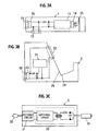
Fig. 2A is a schematic view showing an embodiment of the present invention in which an AC adapter is connected to the cleaning apparatus; -
Fig. 2B is a schematic view showing an embodiment of the present invention in which the AC adapter is connected to the depilator; -
Fig. 3A is a circuit diagram of the depilator of the embodiment of the invention; -
Fig. 3B is a circuit diagram of the cleaning apparatus of the embodiment of the invention; -
Fig. 3C is a circuit diagram of the AC adapter of the embodiment of the invention; -
Fig. 4 is a circuit diagram of the embodiment of the invention having a constant-voltage circuit; -
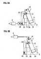
Fig. 5A is a schematic view of the embodiment of the invention in which a terminal connected to an outside includes a transformer and the AC adapter is connected to the second electrical apparatus; and -
Fig. 5B is a schematic view of the embodiment of the invention in which a terminal connected to an outside includes a transformer and the AC adapter is connected to the first electrical apparatus. - Embodiments of the present invention will be explained below in detail with reference to the accompanying drawings. Structures and operations of a depilator 1 that is a first electrical apparatus and a
cleaning apparatus 2 that is a second electrical apparatus of the present embodiment are the same as those of the conventional depilator 1 andcleaning apparatus 2. Therefore, illustration and explanation of the structures and operations which are not subject matter of the present invention will be omitted. The first electrical apparatus and the second electrical apparatus are not limited to the depilator 1 and thecleaning apparatus 2, and the technical idea of the invention can also be applied to other electrical apparatus systems having electrical apparatuses rather than the depilator 1 and thecleaning apparatus 2. - The electrical apparatus system of the present embodiment includes the depilator 1 as the first electrical apparatus that depilates body hair, and the
cleaning apparatus 2 as the second electrical apparatus that cleans the depilator 1, and anAC adapter 3 that supplies DC electric power to the depilator 1 or thecleaning apparatus 2. - The depilator 1 includes a
cutting unit 11 as a first load to which electric power is supplied from theAC adapter 3. The depilator 1 also includes aback surface terminal 12 that is a first electric power transmitting unit. Theback surface terminal 12 has a function for supplying electric power generated by theAC adapter 3 to thecleaning apparatus 2, and a function for supplying the electric power supplied from thecleaning apparatus 2 to the cuttingunit 11. In this embodiment, the depilator 1 includes asecondary battery 13 and a chargingcircuit 14 as a charging unit for charging thesecondary battery 13. Thesecondary battery 13 can be charged through the chargingcircuit 14 by the electric power supplied from theAC adapter 3 or electric power supplied from theconnection terminal 22. - The
cleaning apparatus 2 includes acleaning unit 24 in which thecutting unit 11 is cleaned, and acleaning operation unit 21 as a second load to which electric power is supplied from the AC adapter. Thecleaning operation unit 21 includes a pump, an air valve and a fan apparatus. Thecleaning apparatus 2 also includes aconnection terminal 22 as a second electric power transmitting unit. Theconnection terminal 22 has a function for supplying electric power generated by theAC adapter 3 to the depilator 1, and a function for supplying the electric power supplied from the depilator 1 to thecleaning operation unit 21. - As shown in
Fig. 3C , theAC adapter 3 includes apower supply plug 30 connected to the external power supply, arectifier circuit 31 that rectifies ACvoltage supplied from the external power supply, a switchingconverter 32 that converts the rectified voltage into a predetermined voltage value, and adevice plug 33 connected to theinput unit 20 that receives electric power from the external power supply. The device plug 33 is provided in theinput unit 10 or thecleaning apparatus 2 that is provided in the depilator 1 and that receives electric power from the external power supply. The external power supply and the depilator 1 or thecleaning apparatus 2 are connected to each other through theAC adapter 3. With this configuration, the AC electric power supplied from the external power supply is rectified by therectifier circuit 31, and the rectified electric power is converted into high frequency by the switching circuit of the switchingconverter 32. The frequency is lowered by the transformer to a voltage value that is necessary for an operation of the depilator 1 or thecleaning apparatus 2. The voltage is again rectified and smoothened through a diode and a capacitor to produce DC electric power, and the same is supplied to the depilator 1 or thecleaning apparatus 2. Although the switchingconverter 32 is used as the converter circuit in this embodiment, the converter circuit is not limited to this, and other converter circuit can be constituted. - The cutting
unit 11 includes a blade for cutting the body hair, and a motor for rotating the blade. The cuttingunit 11 is driven by electric power supplied from theAC adapter 3 or theconnection terminal 22. Like the conventional example, thecleaning operation unit 21 includes a pump, an air valve and a fan apparatus. Thecleaning operation unit 21 is driven by electric power supplied from theAC adapter 3 or theback surface terminal 12. - The first electric power transmitting unit is a
back surface terminal 12 provided on a back surface (surface opposed to thecleaning apparatus 2 inFig. 2A ) of the depilator 1. The second electric power transmitting unit is aconnection terminal 22 provided on a contact surface (surface opposed to the depilator 1 inFig. 2A ) of thecleaning apparatus 2. If theback surface terminal 12 and theconnection terminal 22 are brought into contact with each other, they are electrically connected to each other. With this configuration, electric power can be supplied from the depilator 1 to thecleaning apparatus 2, and electric power can be supplied from thecleaning apparatus 2 to the depilator 1. - The operation of the present embodiment is explained below. The depilating method of the body hair is the same as that according to the conventional example. That is, the
AC adapter 3 is connected to the depilator 1, and the cuttingunit 11 is driven by electric power supplied from the external power supply through theAC adapter 3. Alternatively, theAC adapter 3 may not be connected, and the cuttingunit 11 may be driven by electric power supplied from thesecondary battery 13. To clean the depilator 1, when theAC adapter 3 is connected to the cleaning apparatus 2 (seeFig. 2A ), the depilator 1 is allowed to lean along aninclined portion 25 rising upward from one side (left side inFig. 2A ) of thecleaning unit 24 of thecleaning apparatus 2 such that a surface on which aside surface terminal 22 is provided and a surface on which aconnection terminal 12 is provided are opposed to each other, and the cuttingunit 11 is disposed on thecleaning unit 24. Acontrol circuit 23 provided in thecleaning apparatus 2 detects contact between theback surface terminal 12 and theconnection terminal 22. Electric power produced by theAC adapter 3 is supplied to thecleaning operation unit 21 to drive thecleaning operation unit 21. Control is performed such that the cuttingunit 11 of the depilator 1 is cleaned. At the same time, electric power is supplied to the cuttingunit 11 of the depilator 1 through theconnection terminal 22 and theback surface terminal 12 to drive the cuttingunit 11. Thesecondary battery 13 is charged through the chargingcircuit 14. In this embodiment, control is performed such that if the depilator 1 is set on thecleaning apparatus 2, thecleaning operation unit 21 and the cuttingunit 11 are automatically driven and thesecondary battery 13 is automatically charged. Alternatively, control can be performed such that the depilator 1 is disposed at a predetermined position of thecleaning apparatus 2, theback surface terminal 12 and theconnection terminal 22 is brought into contact with each other and then, a switch (not shown) provided on thecleaning apparatus 2 is operated, and thecleaning operation unit 21 and the cuttingunit 11 are driven and thesecondary battery 13 can be charged. - When the
AC adapter 3 is connected to the depilator 1 (seeFig. 2B ), the depilator 1 is allowed to lean along theinclined portion 25 such that the surface on which theside surface terminal 22 is provided and the surface on which theconnection terminal 12 is provided are opposed to each other, and if the cuttingunit 11 is disposed in thecleaning unit 24, acontrol circuit 15 of the depilator 1 detects the contact between theback surface terminal 12 and theconnection terminal 22, electric power produced by theAC adapter 3 is supplied to the cuttingunit 11 to drive the cuttingunit 11, and thesecondary battery 13 is charged through the chargingcircuit 14. At the same time, electric power is supplied to thecleaning operation unit 21 of thecleaning apparatus 2 through theback surface terminal 12 and theconnection terminal 22 to drive thecleaning operation unit 21, and the cuttingunit 11 of the depilator 1 is cleaned. Like the case where theAC adapter 3 is connected to thecleaning apparatus 2, control may not be performed such that if the depilator 1 is disposed in thecleaning apparatus 2, thecleaning operation unit 21 and the cuttingunit 11 are driven and thesecondary battery 13 is charged, but control may be performed such that if the switch (not shown) provided on the depilator 1 is operated, thecleaning operation unit 21 and the cuttingunit 11 are driven and thesecondary battery 13 is charged. - When the
AC adapter 3 is not connected to any of the electrical apparatuses, the depilator 1 is allowed to lean along theinclined portion 25 such that the surface on which theside surface terminal 22 is provided and the surface on which theconnection terminal 12 is provided are opposed to each other, and if the cuttingunit 11 is disposed in thecleaning unit 24, acontrol circuit 15 of the depilator 1 detects the contact between theback surface terminal 12 and theconnection terminal 22, electric power is supplied from thesecondary battery 13 to the cuttingunit 11 to drive the cuttingunit 11. At the same time, electric power is supplied to thecleaning operation unit 21 of thecleaning apparatus 2 through theback surface terminal 12 and theconnection terminal 22, thecleaning operation unit 21 is driven and the cuttingunit 11 of the depilator 1 is cleaned. In this case also, like the case where theAC adapter 3 is connected to the depilator 1, control can be performed such that if the switch (not shown) provided on the depilator 1 is operated, thecleaning operation unit 21 and the cuttingunit 11 are driven. - According to the present embodiment, both the depilator 1 and the
cleaning apparatus 2 are provided with the electric power transmitting units. Thus, no matter whether theAC adapter 3 is connected to depilator 1 or thecleaning apparatus 2, electric power can be supplied to both the depilator 1 and thecleaning apparatus 2. Therefore, if theACadapter3 is connected to one of the electrical apparatuses, it is unnecessary to switch theAC adapter 3, and the degree of convenience is enhanced. Even when theAC adapter 3 is not connected to any of the electrical apparatuses, thecleaning operation unit 21 and thecuttingunit 11 can be driven by thesecondary battery 13 of the depilator 1, and the degree of convenience is enhanced. - The electrical apparatus can includes a constant-
voltage circuit 16 that increases the output voltage from thesecondary battery 13, keeps the voltage constant and sends the same to the back surface terminal 12 (seeFig. 4 ). The constant-voltage circuit 16 includes a conventionally known step-up converter including an inductor, an FET and a diode. The constant-voltage circuit 16 makes the output voltage of thesecondary battery 13 constant by PWM controlling the on duty ratio of the FET, and can supply stable electric power to thecleaning apparatus 2. The circuit structure of the constant-voltage circuit 16 is not limited to the above-described structure. Thecontrol circuit 15 can perform control such that when a predetermined operation time is elapsed from the time when the constant-voltage circuit 16 starts an operation, the constant-voltage circuit 16 is stopped. By limiting the operation time of the constant-voltage circuit 16, deterioration of battery lifetime caused by excessive charging of thesecondary battery 13 can be prevented. In this case, thecontrol circuit 15 is the constant-voltage control unit. - In the present embodiment, to supply electric power between the depilator 1 and the
cleaning apparatus 2, theback surface terminal 12 and theconnection terminal 22 are brought into contact with each other. Alternatively, thedevice plug 33 of theAC adapter 3 and theinput unit 10 of the depilator 1 can include coils, and theinput unit 20 of thecleaning apparatus 2, theback surface terminal 12 and theconnection terminal 22 can include coils, and the electric power can be supplied in a non-contact manner utilizing electromagnetic induction between the coils (seeFig. 5 ). More specifically, thedevice plug 33 of theAC adapter 3, theinput unit 10 of the depilator 1, theinput unit 20 of thecleaning apparatus 2, theback surface terminal 12 and theconnection terminal 22 are respectively provided with coils. With this configuration, thedevice plug 33 and theinput unit 10 of the depilator 1, or theinput unit 20 of thecleaning apparatus 2 are electromagnetically connected with each other, and theback surface terminal 12 and theconnection terminal 22 are electromagnetically connected with each other. In this case, since electrodes (theback surface terminal 12 and the connection terminal 22) are not exposed from surfaces of the depilator 1 and thecleaning apparatus 2, it is possible to prevent water from entering the depilator 1 and thecleaning apparatus 2. - While the embodiment of the present invention has been described above, the invention is not limited to the above embodiment and changes and modifications can be made within the scope of the gist of the present invention.
Claims (5)
- An electrical apparatus system comprising a power generator (3) that produces desired output electric power from input electric power from an external power supply, a first electrical apparatus (1) having a first load (11) to which electric power is supplied from the power generator (3), and a second electrical apparatus (2) having a second load (21) to which electric power is supplied from the power generator (3), the second electrical apparatus (2) being used in combination with the first electrical apparatus (1),
characterized in that,
the first electrical apparatus (1) includes a first electric power transmitting unit (12) configured to supply the electric power produced by the power generator (3) to the second electrical apparatus (2) and to supply the electric power supplied from the second electrical apparatus (2) to the first load (11) , the secondelectrical apparatus (2) includes a second electric power transmitting unit (22) configured to supply electric power produced by the power generator (3) to the first electrical apparatus (1) and to supply electric power supplied from the first electrical apparatus (1) to the second load (21). - The electrical apparatus system according to claim 1, wherein the first electrical apparatus (1) includes a secondary battery (13) that supplies electric power to the first load (11), and a charging unit (14) that charges the secondary battery (13) by the electric power produced by the power generator (3).
- The electrical apparatus system according to claim 2, wherein the first electric power transmitting unit (12) is configured to supply electric power to the second load (21) by the secondary battery (13).
- The electrical apparatus system according to claim 3, wherein the first electrical apparatus (1) includes a constant-voltage circuit (16) that stabilizesbatteryvoltageof the secondary battery (13) to a predetermined constant value.
- The electrical apparatus system according to claim 4, wherein the first electrical apparatus (1) includes a constant-voltage circuit control unit (15) that performs control such that the constant-voltage circuit (16) is stopped when a predetermined operation time is elapsed after a time when the constant-voltage circuit (16) starts an operation.
Applications Claiming Priority (1)
| Application Number | Priority Date | Filing Date | Title |
|---|---|---|---|
| JP2005207575A JP4650135B2 (en) | 2005-07-15 | 2005-07-15 | Electrical equipment system |
Publications (3)
| Publication Number | Publication Date |
|---|---|
| EP1743544A2 EP1743544A2 (en) | 2007-01-17 |
| EP1743544A3 EP1743544A3 (en) | 2008-12-03 |
| EP1743544B1 true EP1743544B1 (en) | 2010-02-10 |
Family
ID=37192524
Family Applications (1)
| Application Number | Title | Priority Date | Filing Date |
|---|---|---|---|
| EP20060014346 Not-in-force EP1743544B1 (en) | 2005-07-15 | 2006-07-11 | Electrical apparatus system |
Country Status (7)
| Country | Link |
|---|---|
| US (1) | US7521820B2 (en) |
| EP (1) | EP1743544B1 (en) |
| JP (1) | JP4650135B2 (en) |
| KR (1) | KR100816167B1 (en) |
| CN (2) | CN100542453C (en) |
| AT (1) | ATE457142T1 (en) |
| DE (1) | DE602006012138D1 (en) |
Families Citing this family (7)
| Publication number | Priority date | Publication date | Assignee | Title |
|---|---|---|---|---|
| JP5007397B2 (en) * | 2007-05-21 | 2012-08-22 | 日立マクセル株式会社 | Electric razor cleaning equipment |
| JP4798227B2 (en) * | 2009-01-15 | 2011-10-19 | パナソニック電工株式会社 | Cleaning device |
| JP5878753B2 (en) * | 2010-12-28 | 2016-03-08 | ヤーマン株式会社 | Mist generator |
| CN102684242A (en) * | 2011-03-18 | 2012-09-19 | 鸿富锦精密工业(深圳)有限公司 | Recharge stand |
| EP3569095A1 (en) * | 2018-05-15 | 2019-11-20 | Braun GmbH | Cleaning and charging station |
| EP3666114A1 (en) | 2018-12-13 | 2020-06-17 | Koninklijke Philips N.V. | Shaving system with shaving device and cleaning device |
| CN112545644A (en) * | 2019-09-25 | 2021-03-26 | 广州星际悦动股份有限公司 | Light intensity control device and control method for depilating instrument |
Family Cites Families (9)
| Publication number | Priority date | Publication date | Assignee | Title |
|---|---|---|---|---|
| DE4402238C2 (en) * | 1994-01-26 | 1996-09-26 | Braun Ag | Cleaning device for the shaving head of a dry shaver |
| JPH07295685A (en) * | 1994-04-28 | 1995-11-10 | Citizen Watch Co Ltd | Information processing system |
| JP3266551B2 (en) * | 1997-09-04 | 2002-03-18 | インターナショナル・ビジネス・マシーンズ・コーポレーション | Power supply system for electrical and electronic equipment |
| KR19980032140U (en) * | 1998-05-19 | 1998-08-17 | 김현식 | Utility charger |
| DE19921677A1 (en) * | 1999-05-18 | 2000-11-23 | Braun Gmbh | Additional device for a small electrical device and method for detecting an electrical and / or magnetic connection between the devices |
| JP2003283609A (en) * | 2002-03-20 | 2003-10-03 | Nec Access Technica Ltd | Portable telephone system, portable telephone terminal, charging base and method for reproducing music used for them |
| US7150285B2 (en) * | 2003-01-21 | 2006-12-19 | Matsushita Electric Works, Ltd. | Cleaning device for a hair removing apparatus |
| JP4036102B2 (en) * | 2003-01-21 | 2008-01-23 | 松下電工株式会社 | Depilation device cleaning system |
| DE10316935A1 (en) * | 2003-04-12 | 2004-11-04 | Braun Gmbh | System of a small electrical device and an associated electrical additional device |
-
2005
- 2005-07-15 JP JP2005207575A patent/JP4650135B2/en not_active Expired - Fee Related
-
2006
- 2006-07-11 AT AT06014346T patent/ATE457142T1/en not_active IP Right Cessation
- 2006-07-11 DE DE200660012138 patent/DE602006012138D1/en active Active
- 2006-07-11 CN CNB2006101019458A patent/CN100542453C/en not_active Expired - Fee Related
- 2006-07-11 EP EP20060014346 patent/EP1743544B1/en not_active Not-in-force
- 2006-07-11 CN CNU2006201294412U patent/CN201008413Y/en not_active Expired - Lifetime
- 2006-07-12 US US11/456,959 patent/US7521820B2/en not_active Expired - Fee Related
- 2006-07-13 KR KR1020060065746A patent/KR100816167B1/en not_active IP Right Cessation
Also Published As
| Publication number | Publication date |
|---|---|
| CN1907173A (en) | 2007-02-07 |
| US20070013343A1 (en) | 2007-01-18 |
| KR20070009431A (en) | 2007-01-18 |
| EP1743544A3 (en) | 2008-12-03 |
| US7521820B2 (en) | 2009-04-21 |
| EP1743544A2 (en) | 2007-01-17 |
| DE602006012138D1 (en) | 2010-03-25 |
| KR100816167B1 (en) | 2008-03-21 |
| CN100542453C (en) | 2009-09-23 |
| ATE457142T1 (en) | 2010-02-15 |
| JP4650135B2 (en) | 2011-03-16 |
| JP2007020882A (en) | 2007-02-01 |
| CN201008413Y (en) | 2008-01-23 |
Similar Documents
| Publication | Publication Date | Title |
|---|---|---|
| EP1743544B1 (en) | Electrical apparatus system | |
| US6286609B1 (en) | AC/DC chopper for power tool | |
| KR101668520B1 (en) | Vacuum cleaner | |
| US8890492B2 (en) | Automatic start/stop device for engine-driven power generator | |
| EP1213815A2 (en) | Power supply systems for power tools | |
| EP1111764A3 (en) | Drive apparatus for vibrating-type compressor | |
| EP0875983A3 (en) | A power supply apparatus | |
| KR101562136B1 (en) | Vacuum cleaner | |
| KR101902292B1 (en) | Apparatus for charging battery in electric vehicle and power supplying method using the same | |
| WO1999039427A1 (en) | Flyback converter with limited output power | |
| EP1990141A1 (en) | Shaver cleaner and shaver system | |
| JP3898355B2 (en) | Uninterruptible power system | |
| KR100405710B1 (en) | Electric automobile battery charging equipment | |
| JP2002315217A (en) | Dc power source apparatus with charging function | |
| KR102010512B1 (en) | Charging controller for electric vehicle | |
| EP1153456B1 (en) | Method in charging a battery powered device and apparatus for working the method | |
| EP0919080B1 (en) | Switched-mode power supply, an electric shaver, and a method of converting direct voltages | |
| JP3552323B2 (en) | Cordless equipment | |
| KR200408364Y1 (en) | Stating equipment for inverter | |
| JP3484448B2 (en) | Power supply | |
| JP4085853B2 (en) | Electronics | |
| JPH11178230A (en) | Charger | |
| JP2004248473A (en) | Charger, charging system, charging control method, and electronic equipment | |
| JP2002354689A (en) | Battery charge device and electrical device | |
| JP2012091276A (en) | Power tool and inverter device used for power tool |
Legal Events
| Date | Code | Title | Description |
|---|---|---|---|
| PUAI | Public reference made under article 153(3) epc to a published international application that has entered the european phase |
Free format text: ORIGINAL CODE: 0009012 |
|
| AK | Designated contracting states |
Kind code of ref document: A2 Designated state(s): AT BE BG CH CY CZ DE DK EE ES FI FR GB GR HU IE IS IT LI LT LU LV MC NL PL PT RO SE SI SK TR |
|
| AX | Request for extension of the european patent |
Extension state: AL BA HR MK YU |
|
| PUAL | Search report despatched |
Free format text: ORIGINAL CODE: 0009013 |
|
| AK | Designated contracting states |
Kind code of ref document: A3 Designated state(s): AT BE BG CH CY CZ DE DK EE ES FI FR GB GR HU IE IS IT LI LT LU LV MC NL PL PT RO SE SI SK TR |
|
| AX | Request for extension of the european patent |
Extension state: AL BA HR MK RS |
|
| RAP1 | Party data changed (applicant data changed or rights of an application transferred) |
Owner name: PANASONIC ELECTRIC WORKS CO., LTD. |
|
| 17P | Request for examination filed |
Effective date: 20090122 |
|
| GRAP | Despatch of communication of intention to grant a patent |
Free format text: ORIGINAL CODE: EPIDOSNIGR1 |
|
| AKX | Designation fees paid |
Designated state(s): AT BE BG CH CY CZ DE DK EE ES FI FR GB GR HU IE IS IT LI LT LU LV MC NL PL PT RO SE SI SK TR |
|
| GRAJ | Information related to disapproval of communication of intention to grant by the applicant or resumption of examination proceedings by the epo deleted |
Free format text: ORIGINAL CODE: EPIDOSDIGR1 |
|
| GRAP | Despatch of communication of intention to grant a patent |
Free format text: ORIGINAL CODE: EPIDOSNIGR1 |
|
| RIN1 | Information on inventor provided before grant (corrected) |
Inventor name: KITAMURA, HIROYASU |
|
| GRAS | Grant fee paid |
Free format text: ORIGINAL CODE: EPIDOSNIGR3 |
|
| GRAA | (expected) grant |
Free format text: ORIGINAL CODE: 0009210 |
|
| AK | Designated contracting states |
Kind code of ref document: B1 Designated state(s): AT BE BG CH CY CZ DE DK EE ES FI FR GB GR HU IE IS IT LI LT LU LV MC NL PL PT RO SE SI SK TR |
|
| REG | Reference to a national code |
Ref country code: GB Ref legal event code: FG4D |
|
| REG | Reference to a national code |
Ref country code: CH Ref legal event code: EP |
|
| REG | Reference to a national code |
Ref country code: IE Ref legal event code: FG4D |
|
| REF | Corresponds to: |
Ref document number: 602006012138 Country of ref document: DE Date of ref document: 20100325 Kind code of ref document: P |
|
| REG | Reference to a national code |
Ref country code: NL Ref legal event code: VDEP Effective date: 20100210 |
|
| LTIE | Lt: invalidation of european patent or patent extension |
Effective date: 20100210 |
|
| PG25 | Lapsed in a contracting state [announced via postgrant information from national office to epo] |
Ref country code: ES Free format text: LAPSE BECAUSE OF FAILURE TO SUBMIT A TRANSLATION OF THE DESCRIPTION OR TO PAY THE FEE WITHIN THE PRESCRIBED TIME-LIMIT Effective date: 20100521 Ref country code: LT Free format text: LAPSE BECAUSE OF FAILURE TO SUBMIT A TRANSLATION OF THE DESCRIPTION OR TO PAY THE FEE WITHIN THE PRESCRIBED TIME-LIMIT Effective date: 20100210 Ref country code: PT Free format text: LAPSE BECAUSE OF FAILURE TO SUBMIT A TRANSLATION OF THE DESCRIPTION OR TO PAY THE FEE WITHIN THE PRESCRIBED TIME-LIMIT Effective date: 20100611 Ref country code: IS Free format text: LAPSE BECAUSE OF FAILURE TO SUBMIT A TRANSLATION OF THE DESCRIPTION OR TO PAY THE FEE WITHIN THE PRESCRIBED TIME-LIMIT Effective date: 20100610 |
|
| PG25 | Lapsed in a contracting state [announced via postgrant information from national office to epo] |
Ref country code: PL Free format text: LAPSE BECAUSE OF FAILURE TO SUBMIT A TRANSLATION OF THE DESCRIPTION OR TO PAY THE FEE WITHIN THE PRESCRIBED TIME-LIMIT Effective date: 20100210 Ref country code: SI Free format text: LAPSE BECAUSE OF FAILURE TO SUBMIT A TRANSLATION OF THE DESCRIPTION OR TO PAY THE FEE WITHIN THE PRESCRIBED TIME-LIMIT Effective date: 20100210 Ref country code: AT Free format text: LAPSE BECAUSE OF FAILURE TO SUBMIT A TRANSLATION OF THE DESCRIPTION OR TO PAY THE FEE WITHIN THE PRESCRIBED TIME-LIMIT Effective date: 20100210 Ref country code: FI Free format text: LAPSE BECAUSE OF FAILURE TO SUBMIT A TRANSLATION OF THE DESCRIPTION OR TO PAY THE FEE WITHIN THE PRESCRIBED TIME-LIMIT Effective date: 20100210 Ref country code: LV Free format text: LAPSE BECAUSE OF FAILURE TO SUBMIT A TRANSLATION OF THE DESCRIPTION OR TO PAY THE FEE WITHIN THE PRESCRIBED TIME-LIMIT Effective date: 20100210 |
|
| PG25 | Lapsed in a contracting state [announced via postgrant information from national office to epo] |
Ref country code: SE Free format text: LAPSE BECAUSE OF FAILURE TO SUBMIT A TRANSLATION OF THE DESCRIPTION OR TO PAY THE FEE WITHIN THE PRESCRIBED TIME-LIMIT Effective date: 20100210 Ref country code: EE Free format text: LAPSE BECAUSE OF FAILURE TO SUBMIT A TRANSLATION OF THE DESCRIPTION OR TO PAY THE FEE WITHIN THE PRESCRIBED TIME-LIMIT Effective date: 20100210 Ref country code: BE Free format text: LAPSE BECAUSE OF FAILURE TO SUBMIT A TRANSLATION OF THE DESCRIPTION OR TO PAY THE FEE WITHIN THE PRESCRIBED TIME-LIMIT Effective date: 20100210 Ref country code: CY Free format text: LAPSE BECAUSE OF FAILURE TO SUBMIT A TRANSLATION OF THE DESCRIPTION OR TO PAY THE FEE WITHIN THE PRESCRIBED TIME-LIMIT Effective date: 20100210 Ref country code: GR Free format text: LAPSE BECAUSE OF FAILURE TO SUBMIT A TRANSLATION OF THE DESCRIPTION OR TO PAY THE FEE WITHIN THE PRESCRIBED TIME-LIMIT Effective date: 20100511 Ref country code: NL Free format text: LAPSE BECAUSE OF FAILURE TO SUBMIT A TRANSLATION OF THE DESCRIPTION OR TO PAY THE FEE WITHIN THE PRESCRIBED TIME-LIMIT Effective date: 20100210 Ref country code: RO Free format text: LAPSE BECAUSE OF FAILURE TO SUBMIT A TRANSLATION OF THE DESCRIPTION OR TO PAY THE FEE WITHIN THE PRESCRIBED TIME-LIMIT Effective date: 20100210 |
|
| PG25 | Lapsed in a contracting state [announced via postgrant information from national office to epo] |
Ref country code: SK Free format text: LAPSE BECAUSE OF FAILURE TO SUBMIT A TRANSLATION OF THE DESCRIPTION OR TO PAY THE FEE WITHIN THE PRESCRIBED TIME-LIMIT Effective date: 20100210 Ref country code: CZ Free format text: LAPSE BECAUSE OF FAILURE TO SUBMIT A TRANSLATION OF THE DESCRIPTION OR TO PAY THE FEE WITHIN THE PRESCRIBED TIME-LIMIT Effective date: 20100210 Ref country code: BG Free format text: LAPSE BECAUSE OF FAILURE TO SUBMIT A TRANSLATION OF THE DESCRIPTION OR TO PAY THE FEE WITHIN THE PRESCRIBED TIME-LIMIT Effective date: 20100510 |
|
| PLBE | No opposition filed within time limit |
Free format text: ORIGINAL CODE: 0009261 |
|
| STAA | Information on the status of an ep patent application or granted ep patent |
Free format text: STATUS: NO OPPOSITION FILED WITHIN TIME LIMIT |
|
| 26N | No opposition filed |
Effective date: 20101111 |
|
| PG25 | Lapsed in a contracting state [announced via postgrant information from national office to epo] |
Ref country code: DK Free format text: LAPSE BECAUSE OF FAILURE TO SUBMIT A TRANSLATION OF THE DESCRIPTION OR TO PAY THE FEE WITHIN THE PRESCRIBED TIME-LIMIT Effective date: 20100210 |
|
| PG25 | Lapsed in a contracting state [announced via postgrant information from national office to epo] |
Ref country code: MC Free format text: LAPSE BECAUSE OF NON-PAYMENT OF DUE FEES Effective date: 20100731 |
|
| REG | Reference to a national code |
Ref country code: CH Ref legal event code: PL |
|
| REG | Reference to a national code |
Ref country code: FR Ref legal event code: ST Effective date: 20110331 |
|
| PG25 | Lapsed in a contracting state [announced via postgrant information from national office to epo] |
Ref country code: CH Free format text: LAPSE BECAUSE OF NON-PAYMENT OF DUE FEES Effective date: 20100731 Ref country code: LI Free format text: LAPSE BECAUSE OF NON-PAYMENT OF DUE FEES Effective date: 20100731 |
|
| PG25 | Lapsed in a contracting state [announced via postgrant information from national office to epo] |
Ref country code: FR Free format text: LAPSE BECAUSE OF NON-PAYMENT OF DUE FEES Effective date: 20100802 |
|
| PG25 | Lapsed in a contracting state [announced via postgrant information from national office to epo] |
Ref country code: IE Free format text: LAPSE BECAUSE OF NON-PAYMENT OF DUE FEES Effective date: 20100711 |
|
| REG | Reference to a national code |
Ref country code: GB Ref legal event code: 746 Effective date: 20111004 |
|
| REG | Reference to a national code |
Ref country code: DE Ref legal event code: R084 Ref document number: 602006012138 Country of ref document: DE Effective date: 20110927 |
|
| PG25 | Lapsed in a contracting state [announced via postgrant information from national office to epo] |
Ref country code: HU Free format text: LAPSE BECAUSE OF FAILURE TO SUBMIT A TRANSLATION OF THE DESCRIPTION OR TO PAY THE FEE WITHIN THE PRESCRIBED TIME-LIMIT Effective date: 20100811 Ref country code: LU Free format text: LAPSE BECAUSE OF NON-PAYMENT OF DUE FEES Effective date: 20100711 |
|
| PG25 | Lapsed in a contracting state [announced via postgrant information from national office to epo] |
Ref country code: TR Free format text: LAPSE BECAUSE OF FAILURE TO SUBMIT A TRANSLATION OF THE DESCRIPTION OR TO PAY THE FEE WITHIN THE PRESCRIBED TIME-LIMIT Effective date: 20100210 |
|
| PGFP | Annual fee paid to national office [announced via postgrant information from national office to epo] |
Ref country code: GB Payment date: 20120711 Year of fee payment: 7 |
|
| PGFP | Annual fee paid to national office [announced via postgrant information from national office to epo] |
Ref country code: IT Payment date: 20120711 Year of fee payment: 7 Ref country code: DE Payment date: 20120704 Year of fee payment: 7 |
|
| GBPC | Gb: european patent ceased through non-payment of renewal fee |
Effective date: 20130711 |
|
| PG25 | Lapsed in a contracting state [announced via postgrant information from national office to epo] |
Ref country code: GB Free format text: LAPSE BECAUSE OF NON-PAYMENT OF DUE FEES Effective date: 20130711 Ref country code: DE Free format text: LAPSE BECAUSE OF NON-PAYMENT OF DUE FEES Effective date: 20140201 |
|
| REG | Reference to a national code |
Ref country code: DE Ref legal event code: R119 Ref document number: 602006012138 Country of ref document: DE Effective date: 20140201 |
|
| PG25 | Lapsed in a contracting state [announced via postgrant information from national office to epo] |
Ref country code: IT Free format text: LAPSE BECAUSE OF NON-PAYMENT OF DUE FEES Effective date: 20130711 |