EP1743073B1 - Bewegliche maschine zum spritzen eines flüssigkeitsstrahls, beispielsweise farbe, auf eine feststehende horizontale fläche zur bildung einer linie - Google Patents
Bewegliche maschine zum spritzen eines flüssigkeitsstrahls, beispielsweise farbe, auf eine feststehende horizontale fläche zur bildung einer linie Download PDFInfo
- Publication number
- EP1743073B1 EP1743073B1 EP05742938A EP05742938A EP1743073B1 EP 1743073 B1 EP1743073 B1 EP 1743073B1 EP 05742938 A EP05742938 A EP 05742938A EP 05742938 A EP05742938 A EP 05742938A EP 1743073 B1 EP1743073 B1 EP 1743073B1
- Authority
- EP
- European Patent Office
- Prior art keywords
- machine
- liquid
- machine according
- paint
- nozzle
- Prior art date
- Legal status (The legal status is an assumption and is not a legal conclusion. Google has not performed a legal analysis and makes no representation as to the accuracy of the status listed.)
- Expired - Lifetime
Links
- 239000003973 paint Substances 0.000 title claims abstract description 62
- 239000007788 liquid Substances 0.000 title claims abstract description 53
- 239000007921 spray Substances 0.000 claims abstract description 32
- 238000011144 upstream manufacturing Methods 0.000 claims abstract description 11
- 230000002572 peristaltic effect Effects 0.000 claims abstract description 10
- 238000005507 spraying Methods 0.000 claims description 27
- 230000007246 mechanism Effects 0.000 claims description 17
- XLYOFNOQVPJJNP-UHFFFAOYSA-N water Substances O XLYOFNOQVPJJNP-UHFFFAOYSA-N 0.000 claims description 16
- 230000000694 effects Effects 0.000 claims description 13
- 238000004140 cleaning Methods 0.000 claims description 11
- 229910052751 metal Inorganic materials 0.000 claims description 9
- 230000009471 action Effects 0.000 claims description 8
- 239000002184 metal Substances 0.000 claims description 8
- 238000004891 communication Methods 0.000 claims description 6
- 229920002994 synthetic fiber Polymers 0.000 claims description 5
- 238000010408 sweeping Methods 0.000 claims description 4
- 230000008878 coupling Effects 0.000 claims description 3
- 238000010168 coupling process Methods 0.000 claims description 3
- 238000005859 coupling reaction Methods 0.000 claims description 3
- 239000000725 suspension Substances 0.000 claims description 2
- 230000008901 benefit Effects 0.000 description 4
- 238000012423 maintenance Methods 0.000 description 4
- 230000015572 biosynthetic process Effects 0.000 description 3
- 238000004062 sedimentation Methods 0.000 description 3
- 238000003756 stirring Methods 0.000 description 3
- 244000025254 Cannabis sativa Species 0.000 description 2
- 239000003990 capacitor Substances 0.000 description 2
- 230000009849 deactivation Effects 0.000 description 2
- 238000006073 displacement reaction Methods 0.000 description 2
- 239000000463 material Substances 0.000 description 2
- 238000002156 mixing Methods 0.000 description 2
- 238000010422 painting Methods 0.000 description 2
- 238000010992 reflux Methods 0.000 description 2
- 230000003014 reinforcing effect Effects 0.000 description 2
- 238000010079 rubber tapping Methods 0.000 description 2
- 239000007787 solid Substances 0.000 description 2
- 238000000638 solvent extraction Methods 0.000 description 2
- 238000004804 winding Methods 0.000 description 2
- 241000196324 Embryophyta Species 0.000 description 1
- 239000004809 Teflon Substances 0.000 description 1
- 229920006362 Teflon® Polymers 0.000 description 1
- 230000004913 activation Effects 0.000 description 1
- 239000008346 aqueous phase Substances 0.000 description 1
- 239000000470 constituent Substances 0.000 description 1
- 238000001816 cooling Methods 0.000 description 1
- 230000006866 deterioration Effects 0.000 description 1
- 238000007865 diluting Methods 0.000 description 1
- 238000001035 drying Methods 0.000 description 1
- 238000004880 explosion Methods 0.000 description 1
- 239000003337 fertilizer Substances 0.000 description 1
- 229920002457 flexible plastic Polymers 0.000 description 1
- 238000011010 flushing procedure Methods 0.000 description 1
- 239000008240 homogeneous mixture Substances 0.000 description 1
- 238000000265 homogenisation Methods 0.000 description 1
- 238000007373 indentation Methods 0.000 description 1
- 230000001788 irregular Effects 0.000 description 1
- 230000002427 irreversible effect Effects 0.000 description 1
- 238000004519 manufacturing process Methods 0.000 description 1
- 230000035515 penetration Effects 0.000 description 1
- 229920003023 plastic Polymers 0.000 description 1
- 239000004033 plastic Substances 0.000 description 1
- 238000003825 pressing Methods 0.000 description 1
- 230000009467 reduction Effects 0.000 description 1
- 238000001175 rotational moulding Methods 0.000 description 1
- 239000002904 solvent Substances 0.000 description 1
- 238000004381 surface treatment Methods 0.000 description 1
Images


Classifications
-
- A—HUMAN NECESSITIES
- A63—SPORTS; GAMES; AMUSEMENTS
- A63C—SKATES; SKIS; ROLLER SKATES; DESIGN OR LAYOUT OF COURTS, RINKS OR THE LIKE
- A63C19/00—Design or layout of playing courts, rinks, bowling greens or areas for water-skiing; Covers therefor
- A63C19/06—Apparatus for setting-out or dividing courts
- A63C19/08—Mechanical means for marking-out
-
- E—FIXED CONSTRUCTIONS
- E01—CONSTRUCTION OF ROADS, RAILWAYS, OR BRIDGES
- E01C—CONSTRUCTION OF, OR SURFACES FOR, ROADS, SPORTS GROUNDS, OR THE LIKE; MACHINES OR AUXILIARY TOOLS FOR CONSTRUCTION OR REPAIR
- E01C23/00—Auxiliary devices or arrangements for constructing, repairing, reconditioning, or taking-up road or like surfaces
- E01C23/16—Devices for marking-out, applying, or forming traffic or like markings on finished paving; Protecting fresh markings
- E01C23/20—Devices for marking-out, applying, or forming traffic or like markings on finished paving; Protecting fresh markings for forming markings in situ
- E01C23/22—Devices for marking-out, applying, or forming traffic or like markings on finished paving; Protecting fresh markings for forming markings in situ by spraying
Definitions
- the present invention relates to a mobile machine for projecting onto a fixed surface a jet of liquid, for example paint, for the purpose of tracing a colored line. More specifically, the invention relates to a machine for drawing lines by spraying liquid paint and joint movement, mainly for tracing the boundaries of the playing areas of a sports field.
- Patent is known EP 302,037 a machine for tracing bands on a sports field in order to delimit the playing areas, these strips being formed by projecting a liquid paint.
- This scribing machine is manually movable and comprises a frame mounted on wheels, provided with an operating handle, on which are installed a paint tank and a pump in communication relation on the one hand with said tank and on the other hand with a spray nozzle installed at the front of the machine frame.
- the pump of the peristaltic type, is engaged by its rotor with the axle of one of the chassis wheel trains.
- the stator of this pump has, facing the rotor, an arcuate arcuate surface of circle circumference on which the rollers of the rotor compress a suction tube and discharge the paint.
- a closed type expansion tank To absorb the pressure and the flow rate of the pump while the nozzle is still closed is provided upstream of the nozzle, a closed type expansion tank.
- This expansion tank occupies a lower level with respect to the bottom of the paint tank and comprises a sealed chamber in which penetrates on the one hand the delivery tube of the pump and on the other hand the tube feeding the nozzle spray.
- the spray nozzle When the spray nozzle is closed, the penetration of the paint into the vessel compresses the air mass contained therein. The energy thus accumulated is then returned to the spraying circuit with a view, for example, to spraying paint without actuating the pump.
- This expansion vessel further comprises a manometer which informs the user on the pressure in the spraying circuit. In this way the user can know if the pressure is sufficient to start the marking.
- stator is movably mounted and can be angularly removed from its normal position of use by a deactivation mechanism.
- This mechanism essentially comprises a traction cable, sheathed, secured to an operating handle attached to the handle. The spacing movement of the stator is effected against the action of a return spring which tends to bring said stator back to its initial position, that is to say in the activation position of the pump .
- This deactivation mechanism in practice, is also used to deactivate the pump when the machine is towed back which avoids any backflow of paint to the tank.
- Another disadvantage of the machine is closely related to the nature of the paint used.
- the latter is usually obtained by diluting in water a base paint in aqueous phase subject to sedimentation, so that a longer or shorter period of non-use of the machine results in a deposit of the paint on the bottom of the tank.
- this machine has no means of automatic stirring of the paint before use so that if the user is not careful, only water with low paint and therefore poorly colored will be sprayed. The quality of the marking will be greatly affected.
- Another disadvantage of this machine lies in the fact that lying on its side for the purpose of its maintenance for example, paint present in the expansion tank and in the spraying circuit can flow back to the manometer and close the latter. irreversible. This disadvantage results in the obligation to replace the manometer.
- the object of the present invention is to overcome the drawbacks mentioned above by using a machine of the aforementioned type for which there is no need to disengage the pump when it is moving forward with the spray nozzle closed, the pump being then used to stir the paint contained in the tank.
- Another object of the present invention is to provide a self-cleaning machine.
- Another object of the present invention is to provide a machine with particularly simple means to prevent paint from flowing back to the manometer when lying on its side.
- Another object of the present invention is to provide a machine with a simplified but solid chassis.
- the machine for projecting on the fixed horizontal surface on which it evolves, a jet of liquid, for example paint for the formation on this surface of a mark in the form of a line, said machine comprising a frame, a front wheel set and a rear wheel set, a liquid spraying tank, at least one spraying nozzle installed at the front and a peristaltic pump having a rotor coupled to the axle of one of the two sets of wheels and a stator comprising a stator body comprising in view of the rotor and centrally relative to the latter a bearing surface arc circumferential circle on which bears a resiliently radially deformable tubular element under the effect of the thrust of the rollers that includes the rotor, which tubular element is in communication relation on the one hand with the liquid reservoir to be sprayed via a suction tube and on the other hand with the spray nozzle via a supply circuit in liquid, said nozzle or said circuit comprising a control member for the circulation of the liquid to be s
- the machine carries a water tank
- the spray nozzle is removably attached to the front of the machine and the suction tube is removably mounted in the paint tank so that in order to clean the circuit, the suction tube can be immersed in the water tank and the nozzle can be arranged either in the water tank or in the paint tank.
- the cleaning of the machine and more precisely of the pump and the supply circuit can then be done automatically during the return journey from the machine to its technical room.
- the sealed capacity constituting the expansion vessel is constituted by a tubular element, wound on itself in one or more vertical loops fixed to the machine, said tube receiving at the end the manometer.
- the geometric winding axis of the vertical loops is horizontal and parallel to the axis of advance of the machine.
- the metal frame of the machine receives the axle of the rear wheel train and the handling handle and supports a plastic shell equipped with the front wheelset, this particular shell receiving the paint tank, water tank, spray nozzle and paint supply system.
- the rotor of the peristaltic pump is coupled to the rear axle. This avoids any failure in the operation of the pump.
- the rotor of the pump is in coupling relation with the axle which carries it, by means of a pawl mechanism which carries out the coupling of the rotor to the axle when the machine is driven forward and disengages between the rotor and the axle when the machine is driven to the rear. This avoids the backflow of paint to the tank when the machine is driven backwards.
- the stator of the pump is articulated to a support plate, fixed to the shell of the machine and is held in position around the rotor by an elastic member.
- the machine in front of the spray nozzle is provided with a pallet comprising a horizontal lower lip, preferably rectilinear, subject to come into contact with the surface to be painted in order to scan it.
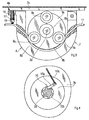
- the machine according to the invention for projecting on the surface on which it evolves, a jet of liquid paint for the formation on this surface of a marking in the form of a line, is manually movable, preferably and comprises a chassis 1, metal, receiving an operating handle 20, and a train 2 of rear wheels.
- This frame 1 supports a rigid hull 4 receiving a front wheel train 3.
- This hull 4 supports in particular a tank 5 of liquid paint, a spray nozzle 6 installed at the front of the machine and the stator 8 of a peristaltic pump 7 whose rotor 9 is coupled to the axle 2a of the rear wheel set via a ratchet mechanism 10 which couples the rotor 9 to the axle 2a when the machine is pushed forward and which the uncoupling when the machine is pulled back, the rotor 9 being fixed in translation on the axle 2a.
- the tube suction 12 has a suction port brought closer to the bottom of the tank.
- the supply circuit 13 comprises a liquid circulation control member 14, such as a tap, operated remotely from the handle 20, by an operating mechanism 15.
- valve 14 can be arranged either in the closed position to prohibit the supply of the nozzle 6 is in the open position to allow feeding of this nozzle.
- the metal frame 1 comprises for example two brackets the metal supporting via two bearings 2b, the axle 2a of the rear wheel train. These two stirrups receive in fixing the handle 20 and the rigid shell 4.
- the handle 20 receives the thrust force or traction exerted by the user for the purpose of moving the machine forward or backward.
- This maneuvering loop 20 is for example constituted by a bent tube so as to substantially marry the contour of a U.
- This handle 20 thus presents two lateral segments 20a intended to be fixed to the two stirrups 1a of the frame 1 and a basal segment 20b constituting a gripping handle.
- the rigid shell 4 obtained for example by rotational molding, is hollow and comprises an upper wall 4a and a lower wall 4b connected to each other. Laterally, the shell 4 comprises two forms of mudguard 4c which constitute stiffness ribs.
- the shell 4 also has two lateral stiffness ribs 4d.
- the shell 4 at the top has one or more indentations provided to receive the tank or tanks, and the various instruments necessary for the operation and maintenance of the machine.
- each stirrup has a U-shaped cross section and comprises a basal wing 1b and two lateral wings 1c.
- the metal stirrups, with their lateral wings 1c, are intended to come on either side respectively of the two lower lateral ribs 4d of the shell 4 to which they are fixed by bolting or other means.
- each yoke 1a receives in fixing one of the two bearings 2b of the axle 2a.
- each bearing 2b of the axle 2a is formed by a block of synthetic material.
- the material used may be that known under the trade name "Teflon".
- the axle 2a On either side of one of the bearings 2b, the axle 2a comprises two stop rings forming shoulders. These stop rings are intended to immobilize the axle 2a in translation relative to the bearings 2b.
- the rear wheels are fixed to the axle 2a for one in translation and rotation and for the other in translation only so as to be rotatable relative to the axle.
- Each stirrup has it projecting on the lower surface of its basal wing 1b a threaded, projecting pin, intended to be engaged in a through bore formed in the lower wall of the shell 4 and opening into the internal volume of said shell.
- the upper wall of the shell 4 has another through bore through which is engaged in the internal volume of the shell 4 a metal sleeve 16 having in the lower part a tapping. By this tapping, the sleeve 16 is screwed to the threaded pin of the yoke corresponding.
- Each sleeve 16 at its upper end is overflowing relative to the shell 4.
- the two sleeves 16 are engaged respectively the two lateral segments 20a of the handle 20 maneuvering.
- each sleeve 16 is equipped with a locking mechanism of the corresponding segment of the operating handle.
- This locking mechanism is constituted for example by a set screw engaged in a radial through thread formed in the protruding portion of the sleeve and pressurized, by screwing, against the operating handle.
- This arrangement also allows, by transferring to the axle 2a part of the thrust force exerted by the user on the handling handle 20, to increase the grip of the rear wheels on the ground and to overcome the against torque exerted by the rotor 9 of the pump 7 on the axle 2a.
- the risk of an irregular drive of the rotor 9 of the pump 7 is eliminated.
- the stator 8 of the peristaltic pump 7 comprises a stator body 8a, endowed, facing the rotor 9 and centrally with respect to the latter, with a bearing surface 8b, in the form of an arc of circumference of circle, on which is supported, a tubular element 11, radially elastically deformable under the effect of the thrust of pressure rollers 9a that includes the rotor 9.
- These pressure rollers 9a are regularly spaced apart from each other.
- Each roll 9a pinches the tubular member, the pinched area moving with the roll. The pinch made ensures a tight partitioning of the tubular element, this partitioning opposing any passage of liquid through the pinched area.
- the value of the circular circumference arc in which the bearing surface 8b is developed is greater than the angular value of the circumferential arc between two consecutive pressure rollers so that the tubular element 11 is always gripped by at least one roller 9a.
- This tubular element 11 is connected at its upstream end to the suction tube 12 and at its downstream end to the feed circuit 13 of the nozzle 6.
- the stator body 8a of the pump 8 is in the form of a hoop and is articulated by one of its ends to a support plate 7a fixed to the bottom wall of the shell 4. At its other end, the stator body 8a cooperates with at least one elastic member 17. Under the effect of the action of this elastic member, the stator 8a is held in position around the rotor 9.
- this other end is provided with at least one through hole in which is engaged a threaded rod 18 secured to the support plate 7a.
- this threaded rod 18 receives in screwing a setting and holding nut 19.
- the elastic member 17, constituted by a coil spring, is mounted on this threaded rod between the stator body 8a and the nut 19
- two threaded rods 18, two springs 17 and two nuts 19 will be provided.
- This tubular element preferably made of flexible synthetic material, is positioned on the surface 8b and is engaged in two through-bores made in the body of the stator 8a respectively upstream and downstream of said surface 8b.
- the plate 7a and bearings 2b support axle 2a are fixed relative to each other.
- a reinforcing element may be disposed between this wall and the bearings 2b, this reinforcing element may, for example take the form of a hoop fixed on the one hand to said wall and on the other hand to the stirrups supporting the bearings 2b.
- the rotor 9 of the pump 7 comprises a sliding bearing 9b by which it is engaged on the axle 2a and a flange 9c fixed to this sliding bearing, this flange carrying on the one hand the rollers 9a, and on the other hand in an articulated manner, the pawl 10a of the ratchet mechanism 10.
- rollers 9a are mounted freely in rotation and fixed in translation on axles fixed cantilevered on the flange 9c of the rotor 9.
- rollers 9a and the axes which support them are parallel to the axle 2a and to the bearing surface 8b of the stator body 8. These rollers 9a are regularly apart from each other.
- the rotor 9 comprises at least three rollers 9a.
- the pawl 10a is mounted on a pin fixed cantilevered on the flange of the rotor 9.
- the pawl 10a is provided to cooperate in form engagement with notches 10b formed in the axle 2a.
- the pawl 10a is returned to the engagement position in the notches 10b by an elastic member 10c such as a coil spring fixed on the one hand to said pawl and on the other hand to the flange 9c of the rotor 9.
- the paint supply circuit 13 comprises upstream of the valve 14 a pressure regulator 21 having an inlet in communication relation with the tubular element 11 via a filter 22, a first paint outlet in relation communicating with the valve 14 and a second paint outlet in communication relation with the tank via a return line 21a.
- This return pipe 21a has a paint discharge port disposed closer to the bottom of the hinge tank.
- the machine can move forward without the need to unload the pump by spraying.
- the pump 7 is discharged into the tank 5 and simultaneously draws the liquid paint contained in the latter, this way, before spraying, an automatic stirring of the paint in the tank 5 and a homogeneous mixture of different constituents of the painting.
- the second output will go to the open state and part of the flow of paint will return to the reservoir and the other part of the flow will supply the nozzle 6.
- the supply circuit 13 downstream of the first output of the regulator 21 and upstream of the valve 14, the supply circuit 13 is associated with a sealed capacity 23 filled with air constituting an expansion vessel.
- This capacity 23 is pressurized by the rise in pressure of the supply circuit under the effect of the flow rate of the pump.
- the user after entering the spray nozzle can perform a tracing by hand or a tracing using a stencil, a characteristic point of the surface to be painted.
- the drawing of straight lines or large curved lines will be done by moving the machine on the ground and keeping the tap open, the nozzle being place on the structure.
- the tracing of the corner lines and the penalty points will be operated the machine stopped, by the user.
- the portion of the feed circuit, downstream of the valve 13 will be constituted by a flexible plastic tube of sufficient length to perform these tracing by hand.
- this length will be of the order of 1.50 meters to 2 meters.
- the capacity 23 is constituted by a tubular element, wound on itself according to one or more vertical loops fixed to the machine.
- the lower end of this tubular element is connected to the supply circuit 13 by a tee fitting.
- the upper end of the tubular element is located above the vertical loop (s) formed (s) and receives a manometer 24.
- This upper end is preferably arranged at a height level greater than maximum level of paint in the tank so that the manometer 24 is always disposed above this level.
- the capacitor 23 will be used a tube with an internal diameter of about 8 millimeters and a length of 2 meters.
- the pressure gauge 24 will be mounted on a plate fixed to the handle 20 and more closely to the handle 20b that the latter comprises, so as to be easily read by the user.
- the loops formed by the tubular element 23 will advantageously be arranged in the shell 4 of the machine, in a chamber that the latter has at the rear.
- the operating mechanism 15 comprises a handle 15a, of the ambidextrous type, articulated to the operating handle 20, a cable 15b under sheath, fixed on the one hand to the handle 15a and on the other hand to an operating lever 14a that has the valve 14 and a resilient member 15c fixed on the one hand to the lever 14a of the operating valve 14 and on the other hand to the rigid shell 4, this resilient member urging the operating lever 14a in the direction of closing the valve 14.
- the operating handle 15a is in the form of a bow and has two end journals by which it is engaged in articulation on the one hand in a radial bore formed in one of the lateral segments 20a of the handle 20. and secondly in a radial bore formed in the other lateral segment of the handle, the handle 15a extending from one lateral segment to the other.
- the capacitance constitutes a reserve of energy and absorbs to a certain extent the pressure variations due, for example, to variations in the speed of the machine.
- Spraying occurs as long as the handle 15a is held by the user against the basal segment 20b of the operating handle. As soon as the user releases the handle 15a, the elastic member 15c brings the valve in the closed position by action on the lever 14a. The cable 15b is then pulled by the lever 14a which returns the handle 15a to the initial position.
- this reflux can result from wear of the rollers 9a or the tube 11, such that the pinching of the tube by each roll is no longer carried out correctly and allows the liquid to pass through the pinched zone.
- This non-return element may be constituted by a non-return valve.
- this non-return valve 39 is placed on the suction tube 12 as can be seen on the figures 1 and 2 .
- non-return valve 39 is disposed at a distance from the suction orifice that comprises the suction tube, but this non-return valve can be mounted in said orifice or in a strainer associated therewith. latest. This arrangement avoids the emptying of the portion of tube immersed in the tank.
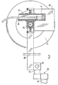
- the spray nozzle 6 is offset laterally with respect to the machine so that the marking performed can not be degraded by the passage of the wheels or by the steps of the user.
- the spray nozzle 6 will produce two streams of paint, one of which will be directed towards the front of the machine and the other towards the rear.
- this arrangement makes it possible to affix the paint on the anterior and posterior faces of the grass strands in a single pass.
- the nozzle 6 is engaged in a removable manner in a vertical sleeve 31 open at both ends, carried by a horizontal support 26 secured to a supporting structure 30 attached to the shell 4 of the machine.
- This horizontal support is transverse to the direction of advancement of the machine.
- the nozzle 6 is provided with a suspension hook 6a through which it is suspended from the vertical sheath 31.
- this vertical sleeve 31 is mounted in a height-adjustable manner on the transverse support 26.
- This arrangement makes it possible to adjust the height of the nozzle 6 with respect to the ground and consequently the width of the line drawn, the jet at the outlet of nozzle being flat and triangular.
- the position of the vertical sleeve 31 along the transverse support 26 will be adjustable.
- two vertical screens 28 in the form of rectangular or triangular walls, subject to come by their lower horizontal edge at most. near the ground. These screens 28 constitute obstacle to the wind, and are intended in particular to protect the paint spray action of the latter.
- the machine is provided with a pallet 28 disposed in front of the nozzle 6, said pallet comprising a lower lip which is subjected to come into contact with the surface to be painted in order to clean it by sweeping and essentially to expel the dew.
- the transverse support 26, laterally to the sleeve 31, is fixed a second horizontal support 32 in the form of a rigid bar extending parallel to the direction of advance of the machine.
- this support 32 carries in front of the nozzle 6, via a elastic link 33, the pallet 34.
- This pallet 34 is advantageously made of an elastically deformable synthetic material.
- the latter is arranged obliquely with respect to the direction of advance of the machine.
- the elastic connection 33 is advantageously constituted by a coil spring with contiguous turns fixed on the one hand to the distal end of the horizontal support 32 and on the other hand to the pallet 34.
- the blade 34 when it encounters an obstacle, which may for example be a goal post, can easily fade against the obstacle, by deformation of the elastic connection. It thus becomes possible to carry out marking up to the obstacle encountered.
- the carrying structure 30 comprises a horizontal tube 35 fixed to the bottom wall 4b of the shell 4, this tube comprising at the front end a vertical sleeve in which is engaged and blocked by a set screw, a tip vertical fixed to the transverse support 26.
- the carrying structure 30 always comprises the horizontal tube 35 fixed to the bottom wall 4b of the shell 4, this tube always comprising at the front end a vertical sleeve in which is engaged and blocked by a set screw, a vertical end piece no longer attached to the transverse support 26, but to one of the two elements 37 of a hinge 36 of horizontal axis and perpendicular to the direction of advance of the machine.
- the other element 38 of the articulation is arranged as a lever arm and receives at the distal end on the one hand the transverse support 26 and on the other hand a support member 27 which can be constituted by a wheel, by a sliding pad or other.
- the machine will also be equipped with a water tank 25 for cleaning the pump, the supply circuit and the spray nozzle 6.
- the suction tube 12 will be immersed in the water tank 25 and the machine will be driven forward. This cleaning can be carried out immediately after tracing, especially during the journey of return of the machine to the technical room.
- the valve 14 is opened by action on the handle 15a.
- the nozzle 6 is immersed in the paint tank or in the water tank.
- the machine as described is mainly intended for marking turf or non-grass sports fields, but it goes without saying that it can be used for the formation of marks on any other type of surface, for example on roads and the like.
- the use of the machine is not limited to the spraying of a paint, so the machine can be used for the spraying of surface treatment liquids such as weed killers, fertilizers etc.
Landscapes
- Engineering & Computer Science (AREA)
- Architecture (AREA)
- Civil Engineering (AREA)
- Structural Engineering (AREA)
- Nozzles (AREA)
- Details Or Accessories Of Spraying Plant Or Apparatus (AREA)
- Spray Control Apparatus (AREA)
- Application Of Or Painting With Fluid Materials (AREA)
Claims (19)
- Bewegliche Maschine zum Spritzen eines Flüssigkeitsstrahls, beispielsweise einer flüssigen Farbe auf eine feststehende horizontale Fläche, auf der sich die Maschine bewegt, zur Bildung einer Markierung in Form einer Linie auf dieser Fläche, wobei diese Maschine aufweist: ein Chassis (1), einen Betätigungsbügel (20), einen vorderen Radsatz (3) und einen hinteren Radsatz (2), einen Flüssigkeitsbehälter (5) für beispielsweise eine flüssige Farbe, mindestens eine Spritzdüse (6), die vorn installiert ist, und eine Peristaltikpumpe (7) mit einem Rotor (9), der mit der Achse (2a) des einen der zwei Radsätze gekoppelt ist, und einem Stator (8) mit einem Statorkörper (8a), der gegenüber dem Rotor (9) und in Bezug auf diesen zentriert eine Druckfläche (8b) in Form eines Kreisumfangsbogens aufweist, auf der sich ein Schlauchelement (11) abstützt, das radial elastisch unter der Wirkung des Drucks von Walzen (9a) verformbar ist, welche der Rotor (9) trägt, wobei das Schlauchelement (11) einerseits mit dem Flüssigkeitsbehälter (5) unter Zwischenschaltung eines Ansaugschlauchs (12) und andererseits mit der Spritzdüse (6) über einen Flüssigkeitsförderkreis (13) in Verbindung steht, wobei die Spritzdüse (6) oder der Förderkreis (13) ein Element (14) zur Steuerung des Kreislaufs der Flüssigkeit aufweist, das mittels eines Betätigungsmechanismus (15) ferngesteuert ist und auf Befehl eine Öffnungsstellung, welche das Spritzen der Flüssigkeit erlaubt, und eine Schließstellung, welche dieses Spritzen verhindert, einnehmen kann, dadurch gekennzeichnet, dass der Flüssigkeitsförderkreis (13) stromaufwärts vom Element (14) zur Steuerung des Flüssigkeitskreislaufs einen Druckregler (21) mit einem Flüssigkeitseinlass, einem ersten Auslass zur Speisung der Düse (6) mittels des Steuerelements (14) und einem zweiten Flüssigkeitsauslass, der mit dem Flüssigkeitsbehälter (5) durch einen Rücklaufkreis (21a) verbunden ist, aufweist, wobei der zweite Auslass einen Flüssigkeitsstrom zum Behälter (5) liefert, wenn der Druck der Flüssigkeit im Regler (21) gleich oder höher als ein Einstellwert wird, wobei der Förderkreis (13) stromabwärts vom ersten Auslass des Druckreglers (21) mit einer mit Luft gefüllten dichten Kapazität (23), welche ein Expansionsgefäß bildet, verbunden ist.
- Maschine nach Anspruch 1, dadurch gekennzeichnet, dass die dichte Kapazität (23) von einem rohr- oder schlauchförmigen Element gebildet ist, das in sich mit einer oder mehreren vertikalen Windung(en) aufgerollt ist, die an der Maschine befestigt ist(sind).
- Maschine nach Anspruch 2, dadurch gekennzeichnet, dass das obere Ende des rohr- oder schlauchförmigen Elements (23) oberhalb des oder der vertikalen Windung(en) liegt, die es bildet, und dass das obere Ende ein Manometer (24) aufnimmt.
- Maschine nach einem der vorangehenden Ansprüche, dadurch gekennzeichnet, dass das metallische Chassis (1) der Maschine die Achse (2a) des hinteren Radsatzes (2) und den Betätigungsbügel (20) aufnimmt und einen Aufbau (4) aus Kunststoff trägt, der mit dem vorderen Radsatz (3) ausgerüstet ist, wobei dieser Aufbau besonders den Farbbehälter (5) und den Farbspeisekreis (13) aufnimmt.
- Maschine nach Anspruch 4, dadurch gekennzeichnet, dass der Rotor (9) der Pump (8) mit der Achse (2a) des hinteren Radsatzes gekuppelt ist.
- Maschine nach Anspruch 5, dadurch gekennzeichnet, dass der Rotor (9) der Pumpe (8) mit der Achse (2a) des hinteren Radsatzes mittels eines Klinkenmechanismus (10) gekuppelt ist, der die Achse (2a) mit dem Rotor (9) kuppelt, wenn die Maschine in Vorwärtsrichtung angetrieben ist, und das Auskuppeln des Rotors realisiert, wenn die Maschine rückwärts angetrieben ist.
- Maschine nach einem der vorangehenden Ansprüche, dadurch gekennzeichnet, dass der Körper des Stators (8a) sich in Form eines Bogens entwickelt und mit einem seiner zwei Enden an einer Trägerplatine (7a) angelenkt ist, die an der unteren Wand (4b) des Aufbaus (4) befestigt ist, während der Körper (8a) mittels seines anderen Endes mit mindestens einem elastischen Element (17) zusammenwirkt, unter dessen Wirkung er in seiner Stellung rings um den Rotor (9) gehalten ist.
- Maschine nach Anspruch 7, dadurch gekennzeichnet, dass das Ende des Bogens, das mit dem elastischen Element (17) zusammanwirkt, mit mindestens einer Durchgangsbohrung versehen ist, in die eine Gewindestange (18) eingesetzt ist, die mit der Trägerplatine (7a) fest verbunden ist, wobei die Stange (18) an ihrem freien Ende eine aufgeschraubte Mutter zur Regelung und zum Halten (19) aufnimmt und das elastische Element (17) auf dieser Gewindestange zwischen dem Körper des Stators (8a) und der Mutter (19) montiert ist.
- Maschine nach einem der vorangehenden Ansprüche, dadurch gekennzeichnet, dass sie mit einem Wasserbehälter (25) ausgerüstet ist, dass die Spritzdüse (6) abnehmbar vorn an der Maschine befestigt ist und der Ansaugschlauch (12) abnehmbar im Farbbehälter (5) montiert ist, damit der Ansaugschlauch (12) in den Wasserbehälter (25) getaucht werden kann und die Spritzdüse (6) entweder im Wasserbehälter (25) oder im Farbbehälter (5) angeordnet werden kann, um den Speisekreis (13) zu reinigen.
- Maschine nach einem der vorangehenden Ansprüche, dadurch gekennzeichnet, dass die Düse (6) abnehmbar in einer an den beiden Enden offenen vertikalen Hülse (31) sitzt, die von einem horizontalen Träger (26) getragen ist, der quer zur Richtung der Vorwärtsbewegung der Maschine verläuft und fest mit einer am Aufbau (4) befestigten Tragstruktur (30) verbunden ist.
- Maschine nach Anspruch 10, dadurch gekennzeichnet, dass die Düse (6) mit einem Haken (6a) zum Aufhängen versehen ist, durch welchen sie an der vertikalen Hülse (31) aufgehängt ist.
- Maschine nach Anspruch 10 oder Anspruch 11, dadurch gekennzeichnet, dass die vertikale Hülse (31) höhenverstellbar am Querträger (26) montiert ist.
- Maschine nach einem der Ansprüche 10 bis 12, dadurch gekennzeichnet, dass die Tragstruktur (30) ein waagerechtes Rohr (35) aufweist, das an der unteren Wand (4b) des Aufbaus (4) befestigt ist, und an seinem vorderen Ende eine vertikale Tülle aufweist, in der eine am Querträger (26) befestigte vertikale Zwinge eingesetzt und durch eine Druckschraube blockiert ist.
- Maschine nach einem der Ansprüche 10 bis 12, dadurch gekennzeichnet, dass die Trägerstruktur (30) ein waagerechtes Rohr (35) aufweist, das an der unteren Wand (4b) des Aufbaus (4) befestigt ist mit einer Endtülle, in der eine vertikale Zwinge eingesetzt und blockiert ist, die an einem der zwei Elemente (37) eines Gelenks (36) mit horizontaler Achse und senkrecht zur Richtung der Vorwärtsbewegung der Maschine fixiert ist, wobei das andere Element (38) des Gelenks (36) als Hebelarm ausgebildet ist und am distalen Ende einerseits den Querträger (26) und andererseits ein Element (27) zum Abstürzen auf dem Boden aufnimmt.
- Maschine nach einem der vorangehenden Ansprüche, gekennzeichnet durch eine vor der Düse (6) angeordnete Palette (34) mit einer unteren Lippe, die dafür eingerichtet ist, dass sie in Berührung mit der zu markierenden Fläche kommt, um sie zu überstreichen.
- Maschine nach Anspruch 15, dadurch gekennzeichnet, dass die Palette (34) mittels einer elastischen Verbindung (33) von einem am Querträger (26) befestigten Halter (32) getragen ist.
- Maschine nach einem der vorangehenden Ansprüche, dadurch gekennzeichnet, dass im Weg der Flüssigkeit stromaufwärts vom Anschlusspunkt der Kapazität (23) am Förderkreis (13) ein Rückschlagelement (39) angeordnet ist.
- Maschine nach Anspruch 17, dadurch gekennzeichnet, dass das Rückschlagelement (39) aus einem Rückschlagventil besteht und dieses Rückschlagventil am Ansaugschlauch (12) angeordnet ist.
- Maschine nach Anspruch 18, dadurch gekennzeichnet, dass das Rückschlagventil (39) in der Ansaugöffnung, welche der Ansaugschlauch (12) aufweist, oder in einem mit der Öffnung verbundenen Saugkopfmontiert ist.
Applications Claiming Priority (2)
| Application Number | Priority Date | Filing Date | Title |
|---|---|---|---|
| FR0403936A FR2868961B1 (fr) | 2004-04-15 | 2004-04-15 | Machine mobile pour projeter sur une surface horizontale fixe un jet de liquide par exemple de la peinture en vue de la formation d'une ligne |
| PCT/EP2005/051465 WO2005111309A1 (fr) | 2004-04-15 | 2005-03-31 | Machine mobile pour projeter sur une surface horizontale fixe un jet de liquide par exemple de la peinture en vue de la formation d'une ligne. |
Publications (2)
| Publication Number | Publication Date |
|---|---|
| EP1743073A1 EP1743073A1 (de) | 2007-01-17 |
| EP1743073B1 true EP1743073B1 (de) | 2008-05-14 |
Family
ID=34944802
Family Applications (1)
| Application Number | Title | Priority Date | Filing Date |
|---|---|---|---|
| EP05742938A Expired - Lifetime EP1743073B1 (de) | 2004-04-15 | 2005-03-31 | Bewegliche maschine zum spritzen eines flüssigkeitsstrahls, beispielsweise farbe, auf eine feststehende horizontale fläche zur bildung einer linie |
Country Status (5)
| Country | Link |
|---|---|
| EP (1) | EP1743073B1 (de) |
| AT (1) | ATE395468T1 (de) |
| DE (1) | DE602005006787D1 (de) |
| FR (1) | FR2868961B1 (de) |
| WO (1) | WO2005111309A1 (de) |
Cited By (1)
| Publication number | Priority date | Publication date | Assignee | Title |
|---|---|---|---|---|
| WO2024256191A1 (en) * | 2023-06-15 | 2024-12-19 | Tinymobilerobots Aps | Mobile line marking robot with peristaltic pump |
Families Citing this family (10)
| Publication number | Priority date | Publication date | Assignee | Title |
|---|---|---|---|---|
| CN100513692C (zh) * | 2007-12-06 | 2009-07-15 | 何堃 | 一种单轮式路面标志喷涂车 |
| GB201313536D0 (en) * | 2013-07-30 | 2013-09-11 | Digital Line Markers Fze | Line marking apparatus having a closed circulation system |
| CN107724222B (zh) * | 2017-11-08 | 2023-06-23 | 南通威而多专用汽车制造有限公司 | 手推式滚刷划线机 |
| CN107675602B (zh) * | 2017-11-08 | 2023-04-25 | 南通威而多专用汽车制造有限公司 | 电动式滚刷划线机 |
| CN110344306B (zh) * | 2019-07-15 | 2024-07-30 | 江苏徐工工程机械研究院有限公司 | 铣刨设备、铣刨设备的控制方法及控制装置 |
| CN111779246B (zh) * | 2020-07-09 | 2024-11-15 | 武汉富洛泰克材料科技有限公司 | 一种快速成型地坪画线设备及画线方法 |
| CN112176845A (zh) * | 2020-10-16 | 2021-01-05 | 湖南筑升信息科技有限公司 | 一种公路建设用标线装置 |
| CN114214911B (zh) * | 2022-01-05 | 2023-09-05 | 衡阳路旺建设有限公司 | 一种道路自动等间距划线装置 |
| CN117107609A (zh) * | 2023-09-27 | 2023-11-24 | 武汉光昱明晟智能科技有限公司 | 一种划线打点系统 |
| CN119869799B (zh) * | 2025-03-26 | 2025-06-20 | 山西省交通新技术发展有限公司 | 一种交通工程施工用交通标线喷涂装置 |
Family Cites Families (4)
| Publication number | Priority date | Publication date | Assignee | Title |
|---|---|---|---|---|
| DE2710013A1 (de) * | 1977-03-08 | 1978-09-14 | Walter Hofmann | Verlegeeinrichtung fuer strassenmarkiermaschine |
| DK161369C (da) * | 1987-07-27 | 1992-01-06 | Trafik Och Fritid Ab | Apparat til kontinuerlig paafoering af en stribe paa et underlag |
| GB9113769D0 (en) * | 1991-06-26 | 1991-08-14 | Supaturf Products Ltd | Dispenser system |
| DE9301759U1 (de) * | 1993-02-09 | 1993-05-19 | Duri, Tobias | Handfahrzeug zum Aufbringen von Streifen oder Linien auf einen Untergrund |
-
2004
- 2004-04-15 FR FR0403936A patent/FR2868961B1/fr not_active Expired - Fee Related
-
2005
- 2005-03-31 AT AT05742938T patent/ATE395468T1/de not_active IP Right Cessation
- 2005-03-31 DE DE602005006787T patent/DE602005006787D1/de not_active Expired - Lifetime
- 2005-03-31 EP EP05742938A patent/EP1743073B1/de not_active Expired - Lifetime
- 2005-03-31 WO PCT/EP2005/051465 patent/WO2005111309A1/fr not_active Ceased
Cited By (1)
| Publication number | Priority date | Publication date | Assignee | Title |
|---|---|---|---|---|
| WO2024256191A1 (en) * | 2023-06-15 | 2024-12-19 | Tinymobilerobots Aps | Mobile line marking robot with peristaltic pump |
Also Published As
| Publication number | Publication date |
|---|---|
| EP1743073A1 (de) | 2007-01-17 |
| WO2005111309A8 (fr) | 2006-09-14 |
| DE602005006787D1 (de) | 2008-06-26 |
| WO2005111309A1 (fr) | 2005-11-24 |
| FR2868961B1 (fr) | 2006-06-16 |
| ATE395468T1 (de) | 2008-05-15 |
| FR2868961A1 (fr) | 2005-10-21 |
Similar Documents
| Publication | Publication Date | Title |
|---|---|---|
| EP1743073B1 (de) | Bewegliche maschine zum spritzen eines flüssigkeitsstrahls, beispielsweise farbe, auf eine feststehende horizontale fläche zur bildung einer linie | |
| EP0017519A2 (de) | Trockenstaubsauger für Bodenflächen | |
| EP0384867A1 (de) | Automatische Bewässerungsmaschine mit einer von einem Hydraulikzylinder angetriebenen Trommel und einem die Kadenz des Hydraulikzylinders steuernden Rechner | |
| EP2618949A1 (de) | Vorrichtung und verfahren zum waschen der innenflächen einer kammer | |
| EP1862222A2 (de) | Anlage zum Versprühen eines Mittels zur Behandlung von Bedachungen und Fassaden | |
| FR2790358A1 (fr) | Machine de fenaison avec au moins un rotor d'andainage muni d'un deflecteur dont la position est reglable | |
| FR2505681A1 (fr) | Appareil de pulverisation | |
| EP0561679B1 (de) | Halbtragbare Vorrichtung und Anlage für die Verteilung von körnigem Schüttgut | |
| FR2485332A1 (fr) | Chariot traineau arroseur semi-automatique ou automatique a utilisations multiples avec differentes options | |
| FR2573618A1 (fr) | Appareil d'arrosage. | |
| EP3083345B1 (de) | Scheibenwischanlage für ein kraftfahrzeug | |
| FR2727880A1 (fr) | Dispositif de nettoyage de tuyaux | |
| FR2476980A1 (fr) | Machine autotractee permettant l'arrosage a l'aide d'un canon employant des liquides divers | |
| FR2634969A1 (fr) | Procede pour l'arrosage de grandes surfaces et dispositif pour la mise en oeuvre de ce procede | |
| FR3004310A1 (fr) | Appareil d'arrosage | |
| EP2188173B1 (de) | Drehbarer gurt zur ausübung von in der luft stattfindenden sportarten | |
| EP0188308A2 (de) | Flüssigkeitsverteilervorrichtung | |
| EP0579565A2 (de) | Flüssigkeitsverteiler und seine Wirkung | |
| FR2796806A1 (fr) | Arroseur a retournement automatique | |
| EP0198781B1 (de) | Heuerntemaschine zum Vorwärts- und Rückwärtsschwaden | |
| EP4662017A1 (de) | Vorrichtung zum reinigen einer glasfläche | |
| WO2002039869A1 (fr) | Dispositif de nettoyage du sol | |
| FR2497692A1 (fr) | Pulverisateur de liquide sur roues demontable | |
| FR2761570A1 (fr) | Rampe d'epandage de liquide charge | |
| FR2662905A1 (fr) | Appareil de pulverisation pour vehicule de traitement agricole. |
Legal Events
| Date | Code | Title | Description |
|---|---|---|---|
| PUAI | Public reference made under article 153(3) epc to a published international application that has entered the european phase |
Free format text: ORIGINAL CODE: 0009012 |
|
| 17P | Request for examination filed |
Effective date: 20061026 |
|
| AK | Designated contracting states |
Kind code of ref document: A1 Designated state(s): AT BE BG CH CY CZ DE DK EE ES FI FR GB GR HU IE IS IT LI LT LU MC NL PL PT RO SE SI SK TR |
|
| DAX | Request for extension of the european patent (deleted) | ||
| GRAP | Despatch of communication of intention to grant a patent |
Free format text: ORIGINAL CODE: EPIDOSNIGR1 |
|
| GRAS | Grant fee paid |
Free format text: ORIGINAL CODE: EPIDOSNIGR3 |
|
| GRAA | (expected) grant |
Free format text: ORIGINAL CODE: 0009210 |
|
| AK | Designated contracting states |
Kind code of ref document: B1 Designated state(s): AT BE BG CH CY CZ DE DK EE ES FI FR GB GR HU IE IS IT LI LT LU MC NL PL PT RO SE SI SK TR |
|
| REG | Reference to a national code |
Ref country code: GB Ref legal event code: FG4D Free format text: NOT ENGLISH |
|
| REG | Reference to a national code |
Ref country code: CH Ref legal event code: EP |
|
| REG | Reference to a national code |
Ref country code: IE Ref legal event code: FG4D |
|
| REF | Corresponds to: |
Ref document number: 602005006787 Country of ref document: DE Date of ref document: 20080626 Kind code of ref document: P |
|
| REG | Reference to a national code |
Ref country code: CH Ref legal event code: PUE Owner name: P.H.M. PHILIPPE MORISSE SAS Free format text: MORISSE, PHILIPPE#LE VILLAGE#32200 GISCARO (FR) -TRANSFER TO- P.H.M. PHILIPPE MORISSE SAS#ROUTE DE PAU LIEUDIT Ref country code: CH Ref legal event code: NV Representative=s name: BOVARD AG PATENTANWAELTE |
|
| REG | Reference to a national code |
Ref country code: GB Ref legal event code: 732E |
|
| PG25 | Lapsed in a contracting state [announced via postgrant information from national office to epo] |
Ref country code: SI Free format text: LAPSE BECAUSE OF FAILURE TO SUBMIT A TRANSLATION OF THE DESCRIPTION OR TO PAY THE FEE WITHIN THE PRESCRIBED TIME-LIMIT Effective date: 20080514 |
|
| PG25 | Lapsed in a contracting state [announced via postgrant information from national office to epo] |
Ref country code: ES Free format text: LAPSE BECAUSE OF FAILURE TO SUBMIT A TRANSLATION OF THE DESCRIPTION OR TO PAY THE FEE WITHIN THE PRESCRIBED TIME-LIMIT Effective date: 20080825 Ref country code: FI Free format text: LAPSE BECAUSE OF FAILURE TO SUBMIT A TRANSLATION OF THE DESCRIPTION OR TO PAY THE FEE WITHIN THE PRESCRIBED TIME-LIMIT Effective date: 20080514 |
|
| NLV1 | Nl: lapsed or annulled due to failure to fulfill the requirements of art. 29p and 29m of the patents act | ||
| PG25 | Lapsed in a contracting state [announced via postgrant information from national office to epo] |
Ref country code: NL Free format text: LAPSE BECAUSE OF FAILURE TO SUBMIT A TRANSLATION OF THE DESCRIPTION OR TO PAY THE FEE WITHIN THE PRESCRIBED TIME-LIMIT Effective date: 20080514 Ref country code: AT Free format text: LAPSE BECAUSE OF FAILURE TO SUBMIT A TRANSLATION OF THE DESCRIPTION OR TO PAY THE FEE WITHIN THE PRESCRIBED TIME-LIMIT Effective date: 20080514 Ref country code: PL Free format text: LAPSE BECAUSE OF FAILURE TO SUBMIT A TRANSLATION OF THE DESCRIPTION OR TO PAY THE FEE WITHIN THE PRESCRIBED TIME-LIMIT Effective date: 20080514 |
|
| PG25 | Lapsed in a contracting state [announced via postgrant information from national office to epo] |
Ref country code: IS Free format text: LAPSE BECAUSE OF FAILURE TO SUBMIT A TRANSLATION OF THE DESCRIPTION OR TO PAY THE FEE WITHIN THE PRESCRIBED TIME-LIMIT Effective date: 20080914 |
|
| REG | Reference to a national code |
Ref country code: IE Ref legal event code: FD4D |
|
| PG25 | Lapsed in a contracting state [announced via postgrant information from national office to epo] |
Ref country code: IE Free format text: LAPSE BECAUSE OF FAILURE TO SUBMIT A TRANSLATION OF THE DESCRIPTION OR TO PAY THE FEE WITHIN THE PRESCRIBED TIME-LIMIT Effective date: 20080514 Ref country code: LT Free format text: LAPSE BECAUSE OF FAILURE TO SUBMIT A TRANSLATION OF THE DESCRIPTION OR TO PAY THE FEE WITHIN THE PRESCRIBED TIME-LIMIT Effective date: 20080514 Ref country code: SE Free format text: LAPSE BECAUSE OF FAILURE TO SUBMIT A TRANSLATION OF THE DESCRIPTION OR TO PAY THE FEE WITHIN THE PRESCRIBED TIME-LIMIT Effective date: 20080814 Ref country code: CZ Free format text: LAPSE BECAUSE OF FAILURE TO SUBMIT A TRANSLATION OF THE DESCRIPTION OR TO PAY THE FEE WITHIN THE PRESCRIBED TIME-LIMIT Effective date: 20080514 Ref country code: DK Free format text: LAPSE BECAUSE OF FAILURE TO SUBMIT A TRANSLATION OF THE DESCRIPTION OR TO PAY THE FEE WITHIN THE PRESCRIBED TIME-LIMIT Effective date: 20080514 |
|
| REG | Reference to a national code |
Ref country code: FR Ref legal event code: TP |
|
| PG25 | Lapsed in a contracting state [announced via postgrant information from national office to epo] |
Ref country code: SK Free format text: LAPSE BECAUSE OF FAILURE TO SUBMIT A TRANSLATION OF THE DESCRIPTION OR TO PAY THE FEE WITHIN THE PRESCRIBED TIME-LIMIT Effective date: 20080514 Ref country code: RO Free format text: LAPSE BECAUSE OF FAILURE TO SUBMIT A TRANSLATION OF THE DESCRIPTION OR TO PAY THE FEE WITHIN THE PRESCRIBED TIME-LIMIT Effective date: 20080514 Ref country code: PT Free format text: LAPSE BECAUSE OF FAILURE TO SUBMIT A TRANSLATION OF THE DESCRIPTION OR TO PAY THE FEE WITHIN THE PRESCRIBED TIME-LIMIT Effective date: 20081014 |
|
| PLBE | No opposition filed within time limit |
Free format text: ORIGINAL CODE: 0009261 |
|
| STAA | Information on the status of an ep patent application or granted ep patent |
Free format text: STATUS: NO OPPOSITION FILED WITHIN TIME LIMIT |
|
| 26N | No opposition filed |
Effective date: 20090217 |
|
| PG25 | Lapsed in a contracting state [announced via postgrant information from national office to epo] |
Ref country code: EE Free format text: LAPSE BECAUSE OF FAILURE TO SUBMIT A TRANSLATION OF THE DESCRIPTION OR TO PAY THE FEE WITHIN THE PRESCRIBED TIME-LIMIT Effective date: 20080514 Ref country code: BG Free format text: LAPSE BECAUSE OF FAILURE TO SUBMIT A TRANSLATION OF THE DESCRIPTION OR TO PAY THE FEE WITHIN THE PRESCRIBED TIME-LIMIT Effective date: 20080814 |
|
| BERE | Be: lapsed |
Owner name: MORISSE, PHILIPPE Effective date: 20090331 |
|
| PG25 | Lapsed in a contracting state [announced via postgrant information from national office to epo] |
Ref country code: MC Free format text: LAPSE BECAUSE OF NON-PAYMENT OF DUE FEES Effective date: 20090331 |
|
| PG25 | Lapsed in a contracting state [announced via postgrant information from national office to epo] |
Ref country code: BE Free format text: LAPSE BECAUSE OF NON-PAYMENT OF DUE FEES Effective date: 20090331 |
|
| PG25 | Lapsed in a contracting state [announced via postgrant information from national office to epo] |
Ref country code: GR Free format text: LAPSE BECAUSE OF FAILURE TO SUBMIT A TRANSLATION OF THE DESCRIPTION OR TO PAY THE FEE WITHIN THE PRESCRIBED TIME-LIMIT Effective date: 20080815 |
|
| REG | Reference to a national code |
Ref country code: CH Ref legal event code: PFA Owner name: P.H.M. PHILIPPE MORISSE SAS Free format text: P.H.M. PHILIPPE MORISSE SAS#ROUTE DE PAU LIEUDIT -TRANSFER TO- P.H.M. PHILIPPE MORISSE SAS#ROUTE DE PAU LIEUDIT |
|
| PG25 | Lapsed in a contracting state [announced via postgrant information from national office to epo] |
Ref country code: LU Free format text: LAPSE BECAUSE OF NON-PAYMENT OF DUE FEES Effective date: 20090331 |
|
| PG25 | Lapsed in a contracting state [announced via postgrant information from national office to epo] |
Ref country code: HU Free format text: LAPSE BECAUSE OF FAILURE TO SUBMIT A TRANSLATION OF THE DESCRIPTION OR TO PAY THE FEE WITHIN THE PRESCRIBED TIME-LIMIT Effective date: 20081115 |
|
| PG25 | Lapsed in a contracting state [announced via postgrant information from national office to epo] |
Ref country code: TR Free format text: LAPSE BECAUSE OF FAILURE TO SUBMIT A TRANSLATION OF THE DESCRIPTION OR TO PAY THE FEE WITHIN THE PRESCRIBED TIME-LIMIT Effective date: 20080514 |
|
| PG25 | Lapsed in a contracting state [announced via postgrant information from national office to epo] |
Ref country code: CY Free format text: LAPSE BECAUSE OF FAILURE TO SUBMIT A TRANSLATION OF THE DESCRIPTION OR TO PAY THE FEE WITHIN THE PRESCRIBED TIME-LIMIT Effective date: 20080514 |
|
| REG | Reference to a national code |
Ref country code: FR Ref legal event code: PLFP Year of fee payment: 12 |
|
| REG | Reference to a national code |
Ref country code: FR Ref legal event code: PLFP Year of fee payment: 13 |
|
| PG25 | Lapsed in a contracting state [announced via postgrant information from national office to epo] |
Ref country code: IT Free format text: LAPSE BECAUSE OF NON-PAYMENT OF DUE FEES Effective date: 20170331 |
|
| REG | Reference to a national code |
Ref country code: FR Ref legal event code: PLFP Year of fee payment: 14 |
|
| PG25 | Lapsed in a contracting state [announced via postgrant information from national office to epo] |
Ref country code: IT Free format text: LAPSE BECAUSE OF NON-PAYMENT OF DUE FEES Effective date: 20170331 |
|
| PGRI | Patent reinstated in contracting state [announced from national office to epo] |
Ref country code: IT Effective date: 20180219 |
|
| PGFP | Annual fee paid to national office [announced via postgrant information from national office to epo] |
Ref country code: FR Payment date: 20230330 Year of fee payment: 19 |
|
| PGFP | Annual fee paid to national office [announced via postgrant information from national office to epo] |
Ref country code: IT Payment date: 20230221 Year of fee payment: 19 Ref country code: GB Payment date: 20230222 Year of fee payment: 19 Ref country code: DE Payment date: 20230221 Year of fee payment: 19 |
|
| PGFP | Annual fee paid to national office [announced via postgrant information from national office to epo] |
Ref country code: CH Payment date: 20230401 Year of fee payment: 19 |
|
| REG | Reference to a national code |
Ref country code: DE Ref legal event code: R119 Ref document number: 602005006787 Country of ref document: DE |
|
| REG | Reference to a national code |
Ref country code: CH Ref legal event code: PL |
|
| GBPC | Gb: european patent ceased through non-payment of renewal fee |
Effective date: 20240331 |
|
| PG25 | Lapsed in a contracting state [announced via postgrant information from national office to epo] |
Ref country code: DE Free format text: LAPSE BECAUSE OF NON-PAYMENT OF DUE FEES Effective date: 20241001 |
|
| PG25 | Lapsed in a contracting state [announced via postgrant information from national office to epo] |
Ref country code: GB Free format text: LAPSE BECAUSE OF NON-PAYMENT OF DUE FEES Effective date: 20240331 |
|
| PG25 | Lapsed in a contracting state [announced via postgrant information from national office to epo] |
Ref country code: FR Free format text: LAPSE BECAUSE OF NON-PAYMENT OF DUE FEES Effective date: 20240331 |
|
| PG25 | Lapsed in a contracting state [announced via postgrant information from national office to epo] |
Ref country code: GB Free format text: LAPSE BECAUSE OF NON-PAYMENT OF DUE FEES Effective date: 20240331 Ref country code: FR Free format text: LAPSE BECAUSE OF NON-PAYMENT OF DUE FEES Effective date: 20240331 Ref country code: DE Free format text: LAPSE BECAUSE OF NON-PAYMENT OF DUE FEES Effective date: 20241001 Ref country code: CH Free format text: LAPSE BECAUSE OF NON-PAYMENT OF DUE FEES Effective date: 20240331 |