EP1742587B1 - Vorrichtung und verfahren zum einführen, positionieren und entfernen eines implantats - Google Patents
Vorrichtung und verfahren zum einführen, positionieren und entfernen eines implantats Download PDFInfo
- Publication number
- EP1742587B1 EP1742587B1 EP05737050A EP05737050A EP1742587B1 EP 1742587 B1 EP1742587 B1 EP 1742587B1 EP 05737050 A EP05737050 A EP 05737050A EP 05737050 A EP05737050 A EP 05737050A EP 1742587 B1 EP1742587 B1 EP 1742587B1
- Authority
- EP
- European Patent Office
- Prior art keywords
- shaft
- head
- channel
- insertion device
- type insertion
- Prior art date
- Legal status (The legal status is an assumption and is not a legal conclusion. Google has not performed a legal analysis and makes no representation as to the accuracy of the status listed.)
- Not-in-force
Links
Images


Classifications
-
- A—HUMAN NECESSITIES
- A61—MEDICAL OR VETERINARY SCIENCE; HYGIENE
- A61B—DIAGNOSIS; SURGERY; IDENTIFICATION
- A61B17/00—Surgical instruments, devices or methods, e.g. tourniquets
- A61B17/56—Surgical instruments or methods for treatment of bones or joints; Devices specially adapted therefor
- A61B17/58—Surgical instruments or methods for treatment of bones or joints; Devices specially adapted therefor for osteosynthesis, e.g. bone plates, screws, setting implements or the like
- A61B17/88—Osteosynthesis instruments; Methods or means for implanting or extracting internal or external fixation devices
- A61B17/92—Impactors or extractors, e.g. for removing intramedullary devices
- A61B17/921—Impactors or extractors, e.g. for removing intramedullary devices for intramedullary devices
-
- A—HUMAN NECESSITIES
- A61—MEDICAL OR VETERINARY SCIENCE; HYGIENE
- A61B—DIAGNOSIS; SURGERY; IDENTIFICATION
- A61B17/00—Surgical instruments, devices or methods, e.g. tourniquets
- A61B17/56—Surgical instruments or methods for treatment of bones or joints; Devices specially adapted therefor
- A61B17/58—Surgical instruments or methods for treatment of bones or joints; Devices specially adapted therefor for osteosynthesis, e.g. bone plates, screws, setting implements or the like
-
- A—HUMAN NECESSITIES
- A61—MEDICAL OR VETERINARY SCIENCE; HYGIENE
- A61B—DIAGNOSIS; SURGERY; IDENTIFICATION
- A61B17/00—Surgical instruments, devices or methods, e.g. tourniquets
- A61B17/56—Surgical instruments or methods for treatment of bones or joints; Devices specially adapted therefor
-
- A—HUMAN NECESSITIES
- A61—MEDICAL OR VETERINARY SCIENCE; HYGIENE
- A61B—DIAGNOSIS; SURGERY; IDENTIFICATION
- A61B17/00—Surgical instruments, devices or methods, e.g. tourniquets
- A61B17/56—Surgical instruments or methods for treatment of bones or joints; Devices specially adapted therefor
- A61B17/58—Surgical instruments or methods for treatment of bones or joints; Devices specially adapted therefor for osteosynthesis, e.g. bone plates, screws, setting implements or the like
- A61B17/88—Osteosynthesis instruments; Methods or means for implanting or extracting internal or external fixation devices
- A61B17/92—Impactors or extractors, e.g. for removing intramedullary devices
- A61B2017/922—Devices for impaction, impact element
Definitions
- the present invention is directed to a device for inserting, positioning and/or removing an implant from bone and, in particular, a device having a portion which can be selectively fixed or freely pivotable and/or rotatable with respect to a body portion of the device.
- Intramedullary rods or rails can be used for internal fixation and reduction of a fractured bone, such as for example a long bone.
- the intramedullary rod is generally inserted into the marrow canal of a long bone, such as the femur, and across the fracture so that the fracture portions are properly aligned in close apposition.
- the rod is typically inserted in one end of the long bone and extends into the shaft of the bone.
- the rod may be designed to be backed-out of the bone to adjust the rod, remove the rod, or pull two halves of a fracture together.
- Various devices can aid in the insertion and/or backing-out and/or removal of the intramedullary rod.
- the implant insertion and positioning device chosen by a surgeon depends on the technique the surgeon desires to use, the desired results, the implant and parameters of the operation. If a surgeon desires to freely hammer an implant into a bone and the surgical procedure so allows, a surgeon can use a hammer-type insertion device having a head and a shaft. Such a surgical hammer-type insertion device is known from US 2002/026196 A1 . The head on such devices has an orientation which is fixed with respect to the shuft. A rod Inserter having an enlarged portion is attached to the intramedullary rod. The surgeon repeatedly strikes the enlarged portion of the rod inserter with the head of the hammer-type insertion device to drive the rod into the marrow canal.
- a surgeon desires or the surgical procedure so requires and/or allows, the surgeon can use a hammer-type insertion device where the head pivots about the shaft.
- a surgical hammer-type insertion device is known from US 5,913,860 A .
- This hammer-type insertion device may be used with a rod inserter, which is attached to the rod and consists of an elongated shaft having proximal and distal ends.
- the shaft may also have an enlarged portion at its proximal end, which is closest to the surgeon, and/or an enlarged portion at its distal end, the end closest to, and typically attached to the intramedullary rod.
- the hammer-type device is positioned on the shaft and travels along the shaft as it undergoes a reciprocating motion that allows a surgeon to repeatedly strike either enlarged, portion.
- a pivotable head allows for ease of movement as the device is reciprocated along the shaft.
- the present invention relates to a device for impacting or inserting an implant into bone, and/or backing-out, extracting or removing the implant from the bone, and/or repositioning an implant in bone.
- the device can be used to insert a rod into a bone, back-out and/or remove a rod from a bone, or reposition a rod in a bone.
- the device comprises a shaft, a head, optionally a channel through the head, and a locking mechanism.
- the locking mechanism may engage the head so that the head does not pivot and/or rotate relative to the shaft.
- the locking mechanism may be disengaged from the head, thereby enabling the head to pivot and/or rotate freely with respect to the shaft.
- the locking mechanism is associated with the shaft of the device.
- the device may also have means for retaining a guide in the optional channel. Additionally, the locking mechanism may have means for tightening the locking mechanism on the shaft.
- the device may be used with an implant inserter which is attached to the rod.
- the inserter may have an aiming arm and an enlarged portion proximate its end.
- One exemplary method of using the device includes the steps of: moving the locking mechanism so that it engages the head, thereby fixing the head relative to the shaft ( i.e ., the head does not pivot, rotate, or translate relative to the shaft); and striking the rod or the enlarged portion of the inserter (if an inserter is used) with the head of the device.
- Another alternative method of using the device involves the steps of: attaching an implant inserter, which comprises a guide to an implant (such as, for example, an intramedullary rod); adjusting the locking mechanism so that it is disengaged from the head, thereby allowing the head to pivot or rotate relative to the shaft; positioning the device onto the guide; and reciprocating the device along the guide.
- the inserter used with this method may have an enlarged portion at one end of the guide proximate the rod and/or an enlarged portion at the other end of the guide.
- An operator can strike the rod or the enlarged portion proximate the rod to insert the rod into the bone.
- an operator can strike the enlarged portion proximate an operator to back-out, remove or reposition the rod from the bone.
- the head of the device may also contain a slot, which communicates with the channel of the head, preferably intersecting the channel at an angle, most preferably perpendicular to the channel.
- the head can be positioned on a guide by moving the slot of the head onto the guide shaft until the shaft reaches the channel. The device is then rotated to align the longitudinal axis of the guide shaft with the longitudinal axis of the channel.
- the head may have a helical slot, which intersects the channel of the head. The helical slot is inserted onto the guide shaft and, as the helical slot is advanced onto the guide shaft, the head threads, rotates or twists until the longitudinal axis of the guide is aligned with the longitudinal axis of the channel.
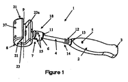
- FIG. 1 is a perspective view of the implant insertion, removal, positioning device according to the present invention
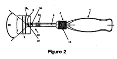
- FIG. 2 is a side view of the device as shown in FIG. 1 ;
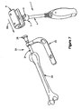
- FIG. 3 is a rear view of an alternative embodiment of the device according to the present invention.
- FIG. 4 is a cross-sectional view of the head of the device as shown in FIGS. 1 and 2 ;
- FIG. 4A is a cross-sectional view of a portion of an exemplary holding member
- FIG. 4B is a cross-sectional view of a portion of another exemplary holding member
- FIG. 4C is a cross-sectional view of a portion of another exemplary holding member
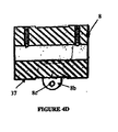
- FIG. 4D is a cross-sectional view of an alternative embodiment of the head of the device as shown in FIGS. 1 and 2 ;
- FIG. 4E is a perspective view of the head of the device as shown in FIGS. 1 and 2 with an alternative exemplary holding member;
- FIG. 5 is a perspective view of an alternative embodiment of the device according to the present invention.
- FIG. 6 is a perspective view of an alternative embodiment of the head of the device according to the present invention.
- FIG. 7 illustrates a method of using the device as shown in FIG. 1 ;
- FIG. 8 illustrates an alternative method of using the device as shown in FIG. 1 .
- FIG. 1 shows an exemplary embodiment of tool 1 for use in inserting, backing-out, extracting, removing and/or positioning an implant.
- Tool 1 can be used by an operator to insert an implant into, back-out or remove an implant from, and/or position or reposition an implant in a bone.
- tool 1 may be used to insert an intermedullary rod or nail into or back-out/remove a rod from the medullary canal of a bone.
- exemplary tool 1 may include a handle 2, a shaft 4, a locking mechanism 7 (including a locking member 6 ), and an impacting body or head 8 pivotally connected to shaft 4. It should be noted that the term pivot and rotate is used interchangeably herein.
- Handle 2 permits an operator to grab and hold tool 1 during use. Handle 2 is preferably ergonomically contoured for use by the operator and may contain grip enhancing surfaces, materials and/or projections. It should be noted that handle 2 is not necessary to the functioning of tool 1 since an operator can grab shaft 4 instead. Handle 2 may be made of plastic, rubber, metal, wood, a composite material ( i.e ., made of at least two materials), or any other suitable material. For example, handle 2 may be made of an impregnated linen or a phenolic resin. Alternatively, handle 2 can be made from a molded polymer ( e.g ., Delrin®). Handle 2 may also have a core material surrounded by another material.
- a composite material i.e ., made of at least two materials
- handle 2 may be made of an impregnated linen or a phenolic resin.
- handle 2 can be made from a molded polymer (e.g ., Delrin®). Handle 2 may also have a core
- an aluminum core may be surrounding by a silicon jacket.
- Various factors can be considered when determining the material used to make handle 2, including ability to withstand sterilization/cleaning (e.g ., using an autoclave; cleaning products used for sterilization in hospitals), feel (e.g ., a molded material gives a softer feel in a operator's hand), weight, durability ( e.g ., ability to withstand impact/load forces, ability to be dropped), resistance to staining (e.g ., from blood or substances used in surgery or to clean tool 1), the ability to withstand heat, and the ability to grip the handle, particularly with latex gloves which are generally used during surgery. Other factors, not listed, may also be relevant.
- the handle 2 can be any shape or size. For example, it may be desirable for handle 2 to be shaped to fit the contours of a hand ( i.e ., ergonomic). Moreover, the end 3 of handle 2 can be flared to prevent handle 2 from slipping from an operator's hand during use. Additionally, to allow for enhanced gripping of handle 2 by an operator, handle 2 may have a grip (not shown), which covers or is positioned in a least a portion of handle 2.
- the grip may be made out of the same materials as handle 2.
- the grip may have indents or protrusions. And, the factors used to select the material for handle 2 are also applicable to choosing material(s) for the grip.
- the grip may be a separate piece from handle 2, for example, the grip may be positioned as an inset (not shown) in the handle.
- the grip may also be over-molded ( i.e ., formed by molding a material over handle 2).
- a grip made of rubber may be used.
- the grip may be integral or monolithic with handle 2 ( i.e ., the handle and grip are made of one piece of material). In such a configuration, the grip portion of handle 2 can be textured.
- Shaft 4 can be attached to handle 2 or be one integral piece with handle 2.
- Shaft 4 can be made from, for example, a hardened material such as stainless steel.
- shaft 4 may be made of any suitable material.
- Various factors may be used to determine the material of shaft 4, including ability to withstand sterilization/cleaning, weight, durability, resistance to staining, and heat treatable. Other factors, not listed, may also be relevant.
- a stainless steel shaft 4 can have a diameter between about approximately 5 mm and about approximately 20 mm, preferably between about approximately 6 mm and about approximately 15 mm, and most preferably between about approximately 7 mm and about approximately 10 mm.
- shaft 4 depends on the material used and can be any diameter so long as the diameter of shaft 4 is sufficient enough so that shaft 4 will not break or bend from repetitive use of tool 1.
- shaft 4 may have a length measured from handle 2 to head 8 between about approximately 20 mm and about approximately 150 mm, preferably between about approximately 50 mm and about approximately 140 mm, and most preferably between about approximately 100 mm and about approximately 130 mm.
- the length of shaft 4 is one factor, amongst others, enabling an operator to properly swing tool 1, and ensuring proper leverage and momentum of tool 1 for hammering.
- shaft 4 can be straight, however, any other shape ( e.g ., S-shape, L-shape, curved), which allows an operator to hammer an implant and enables the proper functioning of the locking mechanism 7 is envisioned.
- Shaft 4 may abut handle 2 or extend through a portion or the entire length of handle 2.
- Shaft 4 can be attached to handle 2 in numerous ways, including friction fitting, welding, chemical or molecular bonding, or gluing.
- shaft 4 can have an external thread (not shown) engaging an internal thread (not shown) of handle 2.
- handle 2 may have an opening 5 which receives a pin, screw, set screw, rod, bar or other retaining means which attaches shaft 4 to lock handle 2 and shaft 4 relative to each other.
- Head 8 is connected to shaft 4. Head 8 may be preferably pivotally and/or rotationally connected to shaft 4. In one embodiment, as shown in FIG. 2 , a portion 4a of distal end 18 of shaft 4 may be flattened or have a reduced diameter with a hole 19 therethrough. Reduced shaft portion 4a may be inserted into a open area 8a ( FIG. 4 ) formed in the head 8. A pin 19a can be positioned through hole 19 such that shaft 4 pivots or rotates about pin 19a. The pin 19a can be fixed with respect to head 8 by, for example, force/press fitting, welding, chemically or molecularly bonding, or gluing into receiving portion(s) (not shown) of head 8.
- a pin can be fixed to shaft 4 (or shaft 4 may have protrusions (not shown) extending from opposite side of shaft 4).
- the pin or protrusions can be positioned in receiving portion(s) (not shown) of head 8 such that head 8 can pivot or rotate with respect to shaft 4. In this manner head 8 can pivot about shaft 4.
- head 8 may have an extension 8b ( FIG. 4D ) (one or more extensions 8b may be used) extending from outer surface 37 of head 8.
- the extension 8b can have hole 8c to receive a pin 19a.
- the hole 19 in shaft 4 can be aligned with hole 8c in extensions 8b .
- Pin 19a may be inserted through hole 8c in extension 8b and hole 19 in shaft 4. In such a configuration, the angle 20 through which shaft 4 can swing or pivot (hereinafter referred to as the "angle of pivot”) is constrained by shaft 4 contacting head 8.
- Shaft 4 and head 8 can be configured so that head 8 has an angle 20 of pivot of about 360° ( e.g ., where the shaft 4 is attached to the side of head 8 ( FIG. 3 )) but more preferably the angle 20 of pivot can be between about approximately 30° and about approximately 270° degrees, and even more preferably between about approximately 30° and about approximately 180° degrees, and most preferably between about approximately 30° and about approximately 90° degrees.
- the angle 20 through which shaft 4 pivots with respect to the head 8 depends upon the clearance of shaft 4 in open area 8a in the head 8.
- the angle 20 of pivot preferably would allow for ergonomic swinging of tool 1.
- shaft 4 may have a ball (not shown) at distal end 18 and head 8 may have a socket (not shown) to receive the ball of shaft 4.
- shaft 4 and head 8 may be connected by a swivel joint (not shown) so that head 8 can be rotated about shaft 4. Any other means of connecting shaft 4 and head 8 can also be used in a manner so that head 8 can pivot and/or rotate with respect to shaft 4 in at least one direction or about at least one axis.
- a locking mechanism 7 may be provided to fix shaft 4 and head 8 with respect to each other, thereby preventing pivotal or rotational movement of head 8 about shaft 4. It should be understood that a locking mechanism includes any mechanism which functions to lock shaft 4 and head 8 relative to each other and which also allows the shaft 4 to be unlocked so that shaft 4 and head 8 can pivot with respect to each other.
- the locking mechanism may be associated with, or may be attached to shaft 4, or may be attachable to shaft 4 ( i.e., capable of being attached/detached from shaft 4 ).
- the locking mechanism can consist of a single piece or more than one piece.
- FIGS. 1 and 2 illustrate an exemplary locking mechanism 7.
- the locking mechanism of FIGS. 1 and 2 includes a locking member 6 disposed about shaft 4 ( FIGS. 1 and 2 ).
- Locking member 6 can be made of a hardened material, such as stainless steel, however, other materials can also be used.
- the same factors that are used to determine the material for shaft 4 can also be used to determine the material, shape, and dimensions of locking member 6. Other factors may also be considered such as the ability to be tightened on shaft 4 and resistance to deformation caused by impact loads from head 8.
- member 6 should be shaped and of sufficient size to allow an operator to grip locking member 6 with his/her fingers or, as discussed in greater detail below, with a tool or to position a tool into locking member 6.
- locking member 6 can be any shape, size, or thickness so long as it can perform its function of keeping shaft 4 and head 8 fixed relative to each other.
- locking member 6 can be a nut.
- locking member 6 can be configured to assist in holding the locking member 6 against the handle 2 or help in fixing the head 8 relative to shaft 4.
- locking member 6 can have a flat portion for engaging a corresponding flat portion of handle 2 and/or head 8.
- Locking member 6 may also have a textured portion, for example teeth, which engages a corresponding textured or smooth portion, for example teeth, on handle 2 and/or head 8.
- Locking member 6 may have internal threads (not shown) to engage proximal threads 12 or distal threads 16. Threads 16 may be located proximate head 8 and function to hold locking member 6 against head 8 at distal end 18 of shaft 4. Threads 12 function to hold locking member 6 at a position on shaft 4 such that locking member 6 does not engage head 8. In FIG. 1 , threads 12 are located proximate handle 2 such that when locking member 6 engages threads 12, a portion 11 of locking member 6 engages enlarged diameter portion 13 and/or handle 2. This configuration allows for locking member 6 to be tightly fastened to the proximal end 14 of shaft 4.
- locking member 6 By threading locking member 6 on proximal threads 12 or by tightly fastening locking member 6 against an enlarged portion, locking member 6 is restrained from moving as the operator uses the insertion, positioning, removing tool 1 . More specifically, locking member 6 will not move along shaft 4 as the device is swung by an operator. Locking member 6 can be tighten on shaft 4 by manually twisting member 6 on threads 12 or 16 ( i.e., an operator uses his/her fingers/hand). Member 6 may also have a grip (e.g ., diamond knurl 17 as shown in FIG. 2 ) which is integral with member 6 and can take various forms, including a rough surface, grooves, or depressions on a portion or around the entire periphery of locking member 6.
- a grip e.g ., diamond knurl 17 as shown in FIG. 2
- locking member 6 can have a grip made from a separate piece of material.
- a grip can be positioned around the outer surface of member 6 or can be inlaid into member 6.
- locking member 6 may be over-molded with a rubber jacket. Over-molded material may be made from any material that provides a better gripping surface for an operator (before, during, or after the operation) than a smooth surface.
- locking member may 6 have one or more opening 15, which can be any shape or size, positioned about the periphery of member 6.
- a device such as a spanner or pin wrench, rod, or bar (not shown) can be positioned in opening 15 and used to twist locking member 6 on shaft 4.
- the spanner or pin wrench, rod, bar, or other device provides an operator with leverage to further tighten locking member 6 on threads 12, 16.
- locking member 6 may be tightened only manually or, alternatively, there can be no manual tightening and the entire tightening step can be performed using a device such as a spanner or pin wrench, rod, bar or other device (not shown), or the member 6 can be manually tightened by the operator turning the member 6 and then further tightened using a tightening tool.
- a device such as a spanner or pin wrench, rod, bar or other device (not shown), or the member 6 can be manually tightened by the operator turning the member 6 and then further tightened using a tightening tool.
- an operator may use, for example, a plier, wrench, or similar device to grab the outer surface of locking member 6 and twist member 6 on threads 12 and 16.
- a screw, set screw, bolt, pin, or other retaining member can be positioned to extend through member 6 and contact the surface and/or extend into threads 12, 16 and/or shaft 4 .
- threads 12 may be located at any location along the length of shaft 4. To lock locking member 6 tightly to shaft 4, a portion of threads 12 may be deformed and/or enlarged portion 13 may be positioned adjacent threads 14. In yet another embodiment, there may be only one threaded portion on shaft 4. The threaded portion preferably would cover enough of shaft 4 so that locking member 6 can be moved from a position adjacent head 8 to a position where member 6 disengages head 8. In still another embodiment, the entire shaft 4 may be threaded. In another embodiment, the shaft 4 may taper from a smaller diameter at distal end 18 to a larger diameter at proximal end 14 or have an enlarged portion.
- Locking member 6 can be force fitted over a portion of the taper or enlarged portion to hold it on shaft 4 at a sufficient distance from head 8 so that head 8 can pivot about shaft 4. Also, in any embodiment, locking member 6, in its disengaged position, may be moveable along shaft 4 ( i.e., not locked to shaft 4) or may be designed to be removed all together from shaft 4 upon disengagement from head 8.
- the locking mechanism 7 may not comprise any threads at all.
- a pin, screw, set screw, bolt, or other retaining means can extend through member 6 and into or through shaft 4.
- the pin, screw, set screw, bolt or other retaining means may extend through opening 15 or some other opening that forms a through hole.
- the through hole may be threaded to engage corresponding threads on the pin, screw, set screw, bolt, or other retaining means. This configuration can be used to hold member 6 on shaft 4 anywhere along the length of shaft 4.
- the locking mechanism may incorporate a bayonet fitting.
- the protrusion(s) may be a single prong, or may extend a portion or the entire length of shaft 4.
- Locking member 6 of this embodiment may have internal groove(s) along its length to receive the protrusion(s).
- a pin, screw, set screw, bolt or other retaining means may be used to hold member 6 against head 8 or at any position along the length of shaft 4.
- a spring (not shown) can be positioned around shaft 4 and bias locking member 6 towards head 8. It should be appreciated that any combination of the embodiments and features disclosed herein can be used as a locking mechanism.
- Such an embodiment may use a pin, set screw, screw, rod, bar, bolt or other means to fix shaft 4 so that shaft 4 does not pivot with respect to head 8.
- a pin, set screw, screw, rod, bar, bolt or other means to fix shaft 4 so that shaft 4 does not pivot with respect to head 8.
- shaft 4 may be connected on the side of head 8.
- Shaft 4 may be shaped similar to a question mark and have a handle 2.
- the connection of shaft 4 and head 8 should allow for pivotal and/or rotational movement of head 8 relative to shaft 4. It should be noted, however, that shaft 4 can be connected anywhere on the outer surface 37 ( FIG. 1 ) of head 8 preferably so that head 8 can pivot and/or rotate with respect to shaft 4 , and tool 1 can be used to hammer an implant into, reposition, or remove/back-out an implant from a bone.
- Head 8 can be any shape or size so long as head 8 can function to impact/strike an implant and/or portion of an insertion device, such as inserter 29 ( FIG. 7 ) in order to impart a force to insert the implant into, reposition, or back-out the implant from a bone.
- an insertion device such as inserter 29 ( FIG. 7 ) in order to impart a force to insert the implant into, reposition, or back-out the implant from a bone.
- Any portion of outer surface 37, but preferably faces 21, 21a of head 8 can be used for impacting/striking an implant or insertion device.
- faces 21, 21a of head 8 may have a piece of material attached thereto which is made of a stronger material than head 8 ( e.g ., a material which is more resistant to dents and/or deformation).
- a piece of titanium may be welded to face 21 and/or 21a.
- a softer material may be attached to faces 21, 21a to absorb the impact force from hammering an implant.
- a piece of rubber can be bonded to face 21 and/or 21a. It should be noted that a separate piece of material can be attached to any portion of head 8 that may contact another surface during hammering.
- Head 8 may be made of stainless steel, but other materials can also be used. Any of the various factors discussed above with regard to choosing a material for shaft 4 or member 6 can be used to determine the material of head 8. In addition, other factors that may be considered is resistance to dents from hammering and impact strength. Moreover, head 8 can have a length between about approximately 30 mm and about approximately 150 mm, preferably between about approximately 40 mm and about approximately 100 mm, and most preferably between about approximately 50 mm and about approximately 75 mm. And, head 8 can have a diameter of between about approximately 30 mm and about approximately 100 mm, preferably between about approximately 35 mm and about approximately 75 mm, and most preferably between about approximately 38 mm and about approximately 60 mm. Various factors can be considered when determining the dimensions of head 8, including the weight and/or mass of the head 8 which is necessary for generating the energy needed to insert an implant.
- Head 8 may also have a channel 23 and a slot 23a intersecting the channel 23. Head 8 and channel 23 may share a longitudinal axis 9, however, head 8 and channel 23 may each have a separate axis, which can be parallel or at any angle with respect to each other. Slot 23a communicates with channel 23 and outer surface 37 of head 8, thereby providing a path for inserting a guide 30, such as longitudinal member 30a shown in FIG. 8 , into channel 23. Slot 23a may run the length of head 8 and intersect channel 23 along its entire length as shown in FIG. 1 . Channel 23 is sized and configured to receive guide 30 of an implant inserter, such as inserter 29 shown in FIG. 7 .
- Channel 23 can be any size so long as guide 30 can be inserted therein and channel 23 allows for reciprocation of head 8 along the guide 30.
- the diameter/thickness of channel 23 can be between about approximately 5 mm and about approximately 35 mm, preferably between about approximately 6 mm and about approximately 24 mm, and most preferably between about approximately 7 mm and about approximately 20 mm.
- FIG. 4 shows a cross-sectional view of head 8 with an exemplary retaining member, ball plunger 25.
- Head 8 may have one or more ball plungers 25.
- Ball plunger 25 may have a housing 28 containing spring 27 and ball bearing 31. The housing is configured to prevent ball bearing 31 from falling out of the housing while, at the same time, allowing a portion of ball bearing 31 to protrude from the housing into channel 23. Ball bearing 31 may also be held in the housing by being fixed to spring 27. Ball bearing 31 is permitted to move up and down in the housing in response to a force thereon, for example, by insertion of rod 30 into channel 23.
- Ball plunger 25 may be positioned in hole 33 (or an opening) of head 8. Plunger 25 can have external threads (not shown) to engage threads (not shown) in the perimeter of hole 33, thus keeping plunger 25 in place.
- plunger 25 may be connected to head 8 in various ways, including force fitting, welding, chemical or molecular bonding, or gluing.
- the position of plunger 25 in channel 23 or slot 23a i.e., the extent to which plunger 25 extends into channel 23 or slot 23a) depends on the guide that is used and the size of the channel 23 .
- ball bearing 31 can be any shape, such as for example a sphere, sloped triangular ( FIG. 4A ), hemi-spherical ( FIG. 4B ), straight sided, or triangle ( FIG. 4C ).
- the shape of ball bearing 31 should allow the guide 30 to move in and out of channel 23 when a predetermined force is applied to remove tool 1 from the guide 30.
- the head 8 preferably is permitted to move along the guide 30.
- the retaining member may extend a portion of the length or the entire length of the channel 23.
- the retaining member may be, for example, a screw, set screw, pin, bar or rod, which can be positioned into or on head 8 and/or channel 23.
- Head 8 may be also be configured such that the retaining member can be adjusted ( i.e. , the holding member can be positioned anywhere within channel 23; the holding member can be adjusted to extend into channel 23 to various extents).
- FIG. 4E illustrates an alternative holding member, component 40 having finger 42.
- component 40 can be used by itself or in conjunction with other holding members such as, for example, ball plungers 25.
- a portion of component 40 (not shown) can be operatively connected to shaft 4.
- a pin, screw, set screw, bar or rod 44 can be positioned through an opening 46 in head 8, though an opening (not shown) in component 40, and/or into a receiving portion (not shown) within head 8.
- any construction that allows component 40 to rotate or pivot within the head 8 is envisioned, including rotation or pivot within slot 48 as shaft 4 is rotated or pivoted.
- the component 40 may be designed so that the finger 42 moves independently of shaft 4.
- Component 40 can be configured such that finger 42 can be extended (partially or entirely) into channel 23 and/or retracted (partially or entirely) into slot 48 and out of channel 23.
- component 40 can be designed so that it moves straight up and down, into and out of channel 23 through slot 48.
- component 40 can be attached to shaft 4.
- component 40 (by itself, by rotating/pivoting component 40 along with shaft 4, or by moving component 40 straight up and down with shaft 4) can be rotated, pivoted, or moved straight down into slot 48.
- Finger 42 can be entirely positioned within the slot 48 so that no portion of finger 42 is within the channel 23. However, finger 42 only needs to be positioned as far into slot 48 as necessary so that guide 30 can enter channel 23. It is desirable that when head 8 is positioned on a guide 30, such as longitudinal member 30a, and reciprocated thereon, the component 40 does not rotate or pivot to such a degree that the head 8 becomes disengage from the guide 30.
- head 8 can have multiple holes 33 (or opening) to allow an operator to adjust the position of the holding member, such as plunger 25, in head 8.
- head 8 and plunger 25 can be configured to allow an operator to adjust the extent to which ball bearing 31 extends into channel 23. It should be noted that any mechanism that can be used to temporarily retain a guide 30, such as longitudinal member 30a, in channel 23 is envisioned.
- a guide 30, such as longitudinal member 30a, of an implant inserter, such as inserter 29, can be twisted into channel 23.
- a slot 35 can extend between outer surface 37 of head 8 and communicate with and intersect channel 23.
- the axis of slot 35 may be transverse to, or more preferably oriented at a 90° angle relative to the longitudinal axis 9 of channel 23. It should be understood that any angle between about approximately 0° and about approximately 180° is also envisioned.
- channel 23 may include opposing side channels 39, which communicate with channel 23 and outer surface 37 of head 8, thereby forming paths for inserting the guide 30, in channel 23.
- the slot 35 in head 8 is positioned onto the guide 30 and then rotated through side channels 39 and into channel 23, such that the longitudinal axis of the guide 30 is aligned with the longitudinal axis 9 of channel 23.
- FIG. 6 shows another alternative embodiment of head 8.
- head 8 can have a helical slot 50.
- Head 8 can be threaded, rotated or twisted onto a guide 30, such as longitudinal member 30a, of an implant inserter, such as inserter 29.
- the helical slot 50 can extend between outer surface 52 of head 8 and communicate with and intersect channel 23.
- Helical slot 50 can also intersect front face 54 and back face 56 of outer surface 52.
- head 4 will thread, twist or rotate into channel 23, such that the longitudinal axis of guide 30 is aligned with the longitudinal axis 9 of channel 23.
- FIGS. 7 and 8 illustrate methods of using tool 1 with a implant inserter device, such as inserter 29, to insert, back-out, remove, position or reposition an implant, such as intramedullary rod 24, from bone 26.
- FIG. 7 shows the use of tool 1 to insert an implant, such as rod 24, into bone 26.
- head 8 is preferably fixed with respect to shaft 4 so that head 8 cannot pivot or rotate about shaft 4.
- a locking mechanism 7, such as locking member 6, can be used to fix head 8 relative to shaft 4. Head 8 is fixed by threading locking member 6 on threads 16 ( FIG. 2 ) at distal end 18. Locking member 6 is tightened as described above so that it firmly engages head 8. It should be understood that any locking mechanism can be used to fix head 8 with respect to shaft 4 so long as head 8 does not pivot and/or rotate on shaft 4. In this configuration, the head 8 is in a "fixed position.”
- head 8 In the fixed position, head 8 can be used to strike or hammer an implant, such as intramedullary rod 24, into bone 26.
- an implant inserter such as inserter 29, may be provided.
- Tool 1 can be used to hammer the implant directly.
- Inserter 29 is attached to rod 24 and includes a mushroom-shaped head portion 28 and an aiming arm 22.
- an operator and/or an assistant holds aiming arm 22 by hand and the operator and/or the assistant strikes portion 28 with head 8 of tool 1.
- rod 24 By swinging tool 1 in direction 32a and striking portion 28, rod 24 is driven in bone 26.
- head 8 preferably may be fixed with respect to shaft 4 when tool 1 is used with an inserter 29 shown in FIG. 7 or with no inserter at all. It is also contemplated that head 8 may pivot with respect to shaft 4 when used with inserter 29 shown in FIG. 6 or without any inserter at all.
- FIG. 8 illustrates the use of tool 1 to insert, back-out, remove, position or reposition an implant, such as rod 24, from bone 26.
- head 8 preferably should be permitted to pivot with respect to shaft 4.
- the locking mechanism 7, such as locking member 6, is disengaged from head 8 by loosening member 6 from threads 16 and moving locking member 6 towards proximal end 14 of shaft 4.
- Locking member 6 may be kept stationary on shaft 4, so that it does not move during swinging of tool 1, by threading locking member 6 on threads 12 ( FIG. 1 ) at proximal end 14.
- the locking member 6 is now spaced a distance from head 8 sufficient enough to allow head 8 to pivot with respect to shaft 4 in a direction shown by arrow 20 ( FIG. 2 ). As discussed above, depending on how shaft 4 and head 8 are attached, head 8 may be able to rotate about shaft 4. In this configuration, the head 6 is in a "toggle position" and can act similar to a slaphammer or slide hammer.
- head 8 may be used with an implant inserter device, such as inserter 29, to hammer an implant, such as rod 24, into and/or out of bone 26.
- Inserter 29 is attached to rod 24 and includes an aiming arm 22, a distal mushroom-shaped head portion 28, a guide 30 ( e.g ., a longitudinal member 30a ,), and a proximal mushroom-shaped head portion 34.
- guide 30 may be any shape, including round, oval, square, rectangular, or other polygon, and can have any thickness so long as head 8 can fit over guide 30 and move therealong.
- Head 8 of tool 1 is positioned on guide 30 by moving slot 23a over guide 30 until guide 30 enters channel 23.
- Guide 30 may be retained in channel 23 using a holding member as described above.
- an operator and/or an assistant holds arm 22 by hand and the operator and/or the assistant reciprocates head 8 on guide 30 in direction 32, repeatedly striking portion 28 with head 8 of tool 1 .
- rod 24 is driven in bone 26.
- the operator and/or the assistant reciprocates head 8 on guide 30 in direction 32, repeatedly striking portion 34 with head 8 of tool 1.
- the tool of FIG. 5 can be used by using the same reciprocating motion as described above.
- a locking mechanism such as locking member 6, can be used to fix head 8 relative to shaft 4 and can be positioned to allow head 8 to toggle with respect to shaft 4. Only the method of positioning head 8 onto guide 30 differs. Slot 35 is positioned onto the guide 30 until the guide 30 intersects channel 23. At this point, the longitudinal axis of the guide 30 is at an angle with the longitudinal axis of channel 23. Head 8 is then rotated such that the guide 30 passes through opposing side channels 39 and into channel 23. At this point, the longitudinal axis of the guide 30 aligns with the longitudinal axis 9 of channel 23.
- a guide 30, such as longitudinal member 30a can be positioned in a helical slot 50. As the helical slot 50 is advanced over the guide 30, the head 8 threads, rotates or twists such that guide 30 is positioned in channel 23. At this point, the longitudinal axis of the guide 30 aligns with the longitudinal axis 9 of channel 23.
Claims (22)
- Einführvorrichtung (1) in der Art eines chirurgischen Hammers zur Verwendung mit einem Knochenimplantat, umfassend: einen Schlagkörper (8), eine Auskehlung (23) durch den Schlagkörper (8), wobei die Auskehlung (23) eine Längsachse aufweist; einen Schaft mit einem proximalen und einem distalen Ende, wobei das distale Ende von dem Schaft funktionell mit dem Schlagkörper derart verbunden ist, dass der Schaft gegenüber dem Schlagkörper geschwenkt werden kann; gekennzeichnet durch
einen Verriegelungsmechanismus, der mindestens zwei Arbeitsstellungen aufweist, eine erste Position, in welcher der Verriegelungsmechanismus es zulässt, dass der Schaft gegenüber dem Schlagkörper geschwenkt wird und eine zweite Position, in welcher der Verriegelungsmechanismus es verhindert, dass der Schaft gegenüber dem Schlagkörper geschwenkt wird. - Einführvorrichtung in der Art eines chirurgischen Hammers nach Anspruch 1, wobei der Schlagkörper eine Achse aufweist und die Längsachse von der Auskehlung parallel zu der Achse des Schlagkörpers ist.
- Einführvorrichtung in der Art eines chirurgischen Hammers nach Anspruch 2, wobei der Schlagkörper eine Außenfläche aufweist und die Auskehlung die Außenfläche des Schlagkörpers durchschneidet.
- Einführvorrichtung in der Art eines chirurgischen Hammers nach Anspruch 3, wobei der Schlagkörper einen Schlitz aufweist, der mit der Auskehlung und der Außenfläche des Schlagkörpers in Verbindung steht.
- Einführvorrichtung in der Art eines chirurgischen Hammers nach Anspruch 4, wobei der Schlitz bezüglich der Längsachse von der Auskehlung in einem Winkel angeordnet ist.
- Einführvorrichtung in der Art eines chirurgischen Hammers nach Anspruch 4, wobei der Schlitz parallel zu der Auskehlung angeordnet ist.
- Einführvorrichtung in der Art eines chirurgischen Hammers nach Anspruch 1, die ferner ein Griffstück aufweist.
- Einführvorrichtung in der Art eines chirurgischen Hammers nach Anspruch 1, wobei mindestens ein Teilbereich von dem Schaft mit einem Gewinde versehen ist.
- Einführvorrichtung in der Art eines chirurgischen Hammers nach Anspruch 8, wobei der Schaft ein Gewinde unmittelbar neben dem Schlagkörper und ein Gewinde unmittelbar am proximalen Ende des Schaftes und dazwischen einen Teilbereich ohne Gewinde aufweist.
- Einführvorrichtung in der Art eines chirurgischen Hammers nach Anspruch 9, wobei der Verriegelungsmechanismus ein Verriegelungselement enthält, das mit dem Schaft verbunden ist, wobei das Verriegelungselement zu einer festgelegten Position von dem Schaft derart verschiebbar ist, dass das Verriegelungselement bezüglich des Schaftes fixiert ist und der Schaft gegenüber dem Schlagkörper geschwenkt werden kann.
- Einführvorrichtung in der Art eines chirurgischen Hammers nach Anspruch 8, wobei der verriegelungsmechanismus ein internes Gewinde aufweist, das in das Gewindeteil von dem Schaft eingreift.
- Einführvorrichtung in der Art eines chirurgischen Hammers nach Anspruch 1, wobei der Verriegelungsmechanismus in der ersten Position den Schlagkörper freigibt und in der zweiten Position den Schlagkörper einrastet.
- Einführvorrichtung in der Art eines chirurgischen Hammers nach Anspruch 1, wobei der Verriegelungsmechanismus Mittel zum Festmachen des Verriegelungsmechanismus an dem Schaft aufweist, wobei vorzugsweise das Mittel zum Festmachen einen Abschnitt für die Aufnahme von einem Werkzeug enthält.
- Einführvorrichtung in der Art eines chirurgischen Hammers nach Anspruch 1, die ferner eine seitliche Auskehlung enthält, wobei die seitliche Auskehlung mit der Auskehlung, der Außenfläche von dem Hammerkopf und dem Schlitz in Verbindung steht.
- Einführvorrichtung in der Art eines chirurgischen Hammers nach Anspruch 1, wobei der Schlitz ein spiralförmiger Schlitz ist, der die Auskehlung und die Außenfläche des klammerkopfes durchschneidet.
- Einführvorrichtung in der Art eines chirurgischen Hammers nach Anspruch 1, wobei mindestens ein Teilbereich von dem distalen Ende des Schaftes ein Gewinde aufweist, wobei vorzugsweise der Verriegelungsmechanismus so konfiguriert und entworfen ist, dass er in das Gewinde in mindestens einem Bereich von dem distalen Ende des Schaftes eingreift, wobei der Verriegelungsmechanismus mit dem Hammerkopf in Kontakt ist, wenn er in das distale Gewinde eingreift, um eine Bewegung von dem Hammerkopf gegenüber dem Schaft zu verhindern.
- Einführvorrichtung in der Art eines chirurgischen Hammers nach Anspruch 1, wobei mindestens ein Teilbereich von dem proximalen Ende des Schaftes ein Gewinde aufweist, wobei vorzugsweise der Verriegelungsmechanismus so konfiguriert und entworfen ist, dass er in das Gewinde in mindestens einem Bereich von dem proximalen Ende des Schaftes eingreift, wobei der Verriegelungsmechanismus in einem Abstand zu dem Hammerkopf positioniert ist, wenn er in das proximale Gewinde eingreift, um eine Bewegung von dem Hammerkopf gegenüber dem Schaft zu ermöglichen.
- Einführvorrichtung in der Art eines chirurgischen Hammers nach Anspruch 1, wobei das Verriegelungselement in der ersten Position dem Hammerkopf freigibt.
- Einführvorrichtung in der Art eines chirurgischen Hammers nach Anspruch 1, die ferner ein Mittel zum Festhalten eines Führungselements in der Auskehlung aufweist.
- Einführvorrichtung in der Art eines chirurgischen Hammers nach Anspruch 1, wobei das Mittel zum Festhalten ein Stößel ist, der Stößel eine Feder und ein Lager in seinem Kopf aufweist, das Lager in der Auskehlung bewegt werden kann, um das Führungselement in der Auskehlung zu halten.
- Einführvorrichtung in der Art eines chirurgischen Hammers nach Anspruch 19, wobei das Mittel zum Festhalten ein Haltefinger ist und der Haltefinger innerhalb der Auskehlung beweglich ist.
- Einführvorrichtung in der Art eines chirurgischen Hammers nach Anspruch 19, wobei das Mittel zum Festhalten einen ersten Durchmesser in der Auskehlung für die Aufnahme des Führungselements definiert, wobei das Mittel zum Festhalten derart verstellbar ist, dass das Mittel zum Festhalten einen zweiten Durchmesser in der Auskehlung für die Aufnahme des Führungselements definiert.
Applications Claiming Priority (2)
| Application Number | Priority Date | Filing Date | Title |
|---|---|---|---|
| US10/831,569 US20050240197A1 (en) | 2004-04-23 | 2004-04-23 | Device and method for inserting, positioning and removing an implant |
| PCT/US2005/013600 WO2005104968A2 (en) | 2004-04-23 | 2005-04-21 | Device and method for inserting, positioning and removing an implant |
Publications (3)
| Publication Number | Publication Date |
|---|---|
| EP1742587A2 EP1742587A2 (de) | 2007-01-17 |
| EP1742587A4 EP1742587A4 (de) | 2009-01-21 |
| EP1742587B1 true EP1742587B1 (de) | 2011-07-13 |
Family
ID=35137479
Family Applications (1)
| Application Number | Title | Priority Date | Filing Date |
|---|---|---|---|
| EP05737050A Not-in-force EP1742587B1 (de) | 2004-04-23 | 2005-04-21 | Vorrichtung und verfahren zum einführen, positionieren und entfernen eines implantats |
Country Status (12)
| Country | Link |
|---|---|
| US (1) | US20050240197A1 (de) |
| EP (1) | EP1742587B1 (de) |
| JP (1) | JP5017095B2 (de) |
| KR (1) | KR101176147B1 (de) |
| CN (2) | CN101803946B (de) |
| AT (1) | ATE515984T1 (de) |
| AU (1) | AU2005237492B2 (de) |
| BR (1) | BRPI0510160A (de) |
| CA (1) | CA2563783C (de) |
| NZ (1) | NZ551306A (de) |
| WO (1) | WO2005104968A2 (de) |
| ZA (1) | ZA200609229B (de) |
Families Citing this family (16)
| Publication number | Priority date | Publication date | Assignee | Title |
|---|---|---|---|---|
| WO2005055845A1 (de) * | 2003-12-08 | 2005-06-23 | Synthes Gmbh | Chirurgischer hammer |
| KR102094835B1 (ko) * | 2012-03-30 | 2020-03-31 | 오쏘돈틱 리써치 앤드 디밸롭먼트 에스.엘. | 원심 이동 장치의 조립 방법 |
| JP6430367B2 (ja) | 2012-04-17 | 2018-11-28 | メルク パテント ゲーエムベーハー | 架橋結合可能なおよび架橋結合されたポリマー、その製造方法およびその使用 |
| US9827011B2 (en) | 2013-03-15 | 2017-11-28 | Biomet Manufacturing, Llc | Polyaxial pivot housing for external fixation system |
| EP3505111B1 (de) | 2013-05-13 | 2020-06-03 | Neo Medical SA | Orthopädisches implantat-set |
| US9770279B2 (en) | 2015-05-18 | 2017-09-26 | Little Engine, LLC | Method and apparatus for extraction of medical implants |
| DE102015007540A1 (de) * | 2015-06-16 | 2016-12-22 | Adalbert Missalla | Chirurgischer Instrumentensatz |
| US10485558B1 (en) * | 2015-07-31 | 2019-11-26 | Joshua Cook | Apparatus and method for harvesting bone |
| WO2018071693A1 (en) * | 2016-10-14 | 2018-04-19 | Zimmer, Inc. | Multi-use tool |
| CA3069434A1 (en) * | 2017-07-10 | 2019-01-17 | Thomas Jefferson University | Dual-function anchor system |
| US20190015131A1 (en) * | 2017-07-14 | 2019-01-17 | Merit Medical Systems, Inc. | Bone access device holder and methods of use |
| BR112020016327A2 (pt) | 2018-02-26 | 2020-12-15 | Neo Medical Sa | Retentor de gaiola de coluna vertebral |
| WO2019169357A1 (en) * | 2018-03-01 | 2019-09-06 | Alden Kris | Prosthetic component extractor |
| CN109247983A (zh) * | 2018-09-20 | 2019-01-22 | 史迎春 | 一种钳式多功能弹性髓内针打入装置 |
| JP2022512769A (ja) * | 2018-11-08 | 2022-02-07 | ネオ・メディカル・ソシエテ・アノニム | 脊椎ケージハンマ |
| WO2021097491A1 (en) * | 2019-11-15 | 2021-05-20 | Paragon 28, Inc. | Instruments, systems, and methods of using |
Family Cites Families (84)
| Publication number | Priority date | Publication date | Assignee | Title |
|---|---|---|---|---|
| US691309A (en) * | 1901-03-16 | 1902-01-14 | Felix S Goldsmith | Prospector's pick or similar tool. |
| US703790A (en) * | 1901-09-26 | 1902-07-01 | Dawson M Humiston | Glazier's hammer. |
| US1822280A (en) * | 1929-06-26 | 1931-09-08 | John F Ervay | Carpenter's hammer |
| US2043442A (en) * | 1935-03-21 | 1936-06-09 | James E Mcneil | Tool holder |
| US2613475A (en) * | 1949-02-04 | 1952-10-14 | Adrien R Mellor | Striking toy |
| US3094021A (en) * | 1960-10-26 | 1963-06-18 | Curtiss Wright Corp | Impact wrench structure for tightening or loosening rod joints |
| US3208450A (en) * | 1962-03-14 | 1965-09-28 | Abelson Louis | Fracture setting tool |
| CH405600A (de) * | 1963-09-26 | 1966-01-15 | Synthes Ag | Marknagel und dazu passendes Einschlag- und Ausziehwerkzeug |
| CH490076A (de) * | 1968-04-25 | 1970-05-15 | Arnold Heinrich Dr Med Huggler | Instrument zur Verwendung mit einer Gelenkkopfprothese für den Oberschenkelknochen |
| US3750500A (en) * | 1971-04-29 | 1973-08-07 | A Peterson | Dowel pin extractor tool |
| US3834393A (en) * | 1973-07-09 | 1974-09-10 | R Goggins | Veterinary surgical tool for enlarging the pelvic girdle of a heifer during parturition |
| US4153053A (en) * | 1977-09-12 | 1979-05-08 | Eleazar Figallo E | Method of reducing malar fractures using a hammer disimpactor |
| AT358715B (de) * | 1978-09-04 | 1980-09-25 | Plansee Metallwerk | Ein- und ausschlagvorrichtung fuer knochen- marknaegel |
| US4222382A (en) * | 1979-01-26 | 1980-09-16 | Massachusetts Institute Of Technology | Femoral component hip joint prosthesis extractor |
| DE2944710A1 (de) * | 1979-11-06 | 1981-05-07 | Christos Dr. Dimakos | Vorrichtung zum entfernen einer knochenzementroehre bei einer reimplantation eines kuenstlichen oberschenkelhalskopfes |
| US4399813A (en) * | 1981-01-22 | 1983-08-23 | Barber Forest C | Apparatus and method for removing a prosthesis embedded in skeletal bone |
| US4399978A (en) * | 1982-02-26 | 1983-08-23 | Moore Charles H | Hand tool with variable inclined head |
| US4462395A (en) * | 1983-03-02 | 1984-07-31 | Johnson Lanny L | Arthroscopic ligamentous and capsular fixation system |
| US4459985A (en) * | 1983-03-04 | 1984-07-17 | Howmedica Inc. | Tibial prosthesis extractor and method for extracting a tibial implant |
| RO89820B1 (ro) * | 1985-11-05 | 2002-06-28 | îNTREPRINDEREA INDUSTRIA TEHNICO MEDICALA | Implanturi elastice, pentru osteosinteza elastica stabila, a fracturilor femurului si, respectiv, tibiei, precum si instrumentar de lucru |
| US4924056A (en) * | 1986-08-13 | 1990-05-08 | Bevilacqua Richard M | Dent puller and method of use |
| US4805494A (en) * | 1987-08-24 | 1989-02-21 | Richard Santoro | Articulate hammer |
| US5122146A (en) * | 1988-02-04 | 1992-06-16 | Pfizer Hospital Products Group, Inc. | Apparatus for reducing a fracture |
| US5484437A (en) * | 1988-06-13 | 1996-01-16 | Michelson; Gary K. | Apparatus and method of inserting spinal implants |
| US4919153A (en) * | 1988-10-11 | 1990-04-24 | Origin Medsystems, Inc. | Method and apparatus for removing pre-placed prosthetic joints and preparing for their replacement |
| US5156606A (en) * | 1988-10-11 | 1992-10-20 | Zimmer, Inc. | Method and apparatus for removing pre-placed prosthetic joints and preparing for their replacement |
| US4993410A (en) * | 1989-05-01 | 1991-02-19 | Kimsey Timothy P | Prosthetic removal device |
| US5116335A (en) * | 1989-09-18 | 1992-05-26 | Hannon Gerard T | Intramedullary hybrid nail and instrumentation for installation and removal |
| US5122144A (en) * | 1989-09-26 | 1992-06-16 | Kirschner Medical Corporation | Method and instrumentation for unicompartmental total knee arthroplasty |
| US5152792A (en) * | 1990-02-06 | 1992-10-06 | Zimmer, Inc. | Apparatus and method for gauging and controlling process steps used to remove prosthetic joints |
| US5041120A (en) * | 1990-01-19 | 1991-08-20 | Origin Medsystems, Inc. | Multipart kit and method of using the same to remove cement used to secure prosthetic joints |
| US5078718A (en) * | 1990-04-17 | 1992-01-07 | Origin Medsystems, Inc. | Multi-part method and apparatus for removing pre-placed prosthetic joints and preparing for their replacement |
| US5222957A (en) * | 1990-04-17 | 1993-06-29 | Zimmer, Inc. | Method and apparatus for extracting a cement mantle from a bone recess |
| US5122143A (en) * | 1990-04-17 | 1992-06-16 | Origin Medsystems, Inc. | Method and apparatus for extracting a cement mantle from a bone recess |
| US5190550A (en) * | 1990-08-02 | 1993-03-02 | Exactech, Inc. | Locking surgical tool handle system |
| US5100404A (en) * | 1990-09-04 | 1992-03-31 | Beth Israel Hospital | Intramedullary nailing method and apparatus |
| US5190551A (en) * | 1990-12-14 | 1993-03-02 | Zimmer, Inc. | Controlled apparatus and method for extracting cement mantles from bone recesses |
| US5098437A (en) * | 1991-02-13 | 1992-03-24 | Pfizer Hospital Products Group, Inc. | Acetabular cup positioning insert |
| US5280738A (en) * | 1991-08-20 | 1994-01-25 | Liou Mou Tang | Hammer with an angle-adjustable head |
| US5429640A (en) * | 1992-11-27 | 1995-07-04 | Clemson University | Intramedullary rod for fracture fixation of femoral shaft independent of ipsilateral femoral neck fracture fixation |
| EP0683651B1 (de) * | 1993-02-10 | 1999-09-29 | Sulzer Spine-Tech Inc. | Werkzeugsatz zur stabilisierung der wirbelsäule |
| DE59409052D1 (de) * | 1994-04-25 | 2000-02-10 | Sulzer Orthopaedie Ag Baar | Ausziehinstrument für einen Schaft einer Hüftgelenkprothese oder einer entsprechenden Raspel |
| US5591169A (en) * | 1994-06-14 | 1997-01-07 | Benoist; Louis | Device and method for positioning and holding bone fragments in place |
| GB9416215D0 (en) * | 1994-08-11 | 1994-10-05 | Howmedica | Acetabular bone graft impactor |
| US6024746A (en) * | 1995-05-31 | 2000-02-15 | Lawrence Katz | Method and apparatus for locating bone cuts at the distal condylar femur region to receive a femoral prothesis and to coordinate tibial and patellar resection and replacement with femoral resection and replacement |
| US6077270A (en) * | 1995-05-31 | 2000-06-20 | Katz; Lawrence | Method and apparatus for locating bone cuts at the distal condylar femur region to receive a femoral prothesis and to coordinate tibial and patellar resection and replacement with femoral resection and replacement |
| US5683391A (en) * | 1995-06-07 | 1997-11-04 | Danek Medical, Inc. | Anterior spinal instrumentation and method for implantation and revision |
| US5766174A (en) * | 1995-09-26 | 1998-06-16 | Orthologic Corporation | Intramedullary bone fixation device |
| US5871204A (en) * | 1995-12-04 | 1999-02-16 | Spirer; Steven E. | Hand tool with adjustable head |
| US5690636A (en) * | 1995-12-21 | 1997-11-25 | Johnson & Johnson Professional, Inc. | Punch system for tibial prosthesis |
| CA2193451C (en) * | 1995-12-21 | 2005-11-01 | Diana F. Mccue | Instrument system for knee prosthesis implantation with universal handle or slap hammer |
| USD381884S (en) * | 1996-02-06 | 1997-08-05 | Spirer Steven E | Angled head hammer |
| US5718707A (en) * | 1997-01-22 | 1998-02-17 | Mikhail; W. E. Michael | Method and apparatus for positioning and compacting bone graft |
| GB9714003D0 (en) * | 1997-07-02 | 1997-09-10 | Howmedica | Apparatus for impacting bone chips in a bone canal |
| GB9714004D0 (en) * | 1997-07-02 | 1997-09-10 | Howmedica | Apparatus for releasably attaching an impaction hammer to a proximal impactor to be impacted into a bone |
| US5913860A (en) * | 1998-02-27 | 1999-06-22 | Synthes (Usa) | Surgical nail inserter |
| US6258095B1 (en) * | 1998-03-28 | 2001-07-10 | Stryker Technologies Corporation | Methods and tools for femoral intermedullary revision surgery |
| US6063091A (en) * | 1998-10-13 | 2000-05-16 | Stryker Technologies Corporation | Methods and tools for tibial intermedullary revision surgery and associated tibial components |
| US6261289B1 (en) * | 1998-10-26 | 2001-07-17 | Mark Levy | Expandable orthopedic device |
| US6174311B1 (en) * | 1998-10-28 | 2001-01-16 | Sdgi Holdings, Inc. | Interbody fusion grafts and instrumentation |
| ATE464847T1 (de) * | 1999-01-25 | 2010-05-15 | Warsaw Orthopedic Inc | Instrument zur schaffung eines zwischenwirbelraumes für die aufnahme eines implantates |
| US6648895B2 (en) * | 2000-02-04 | 2003-11-18 | Sdgi Holdings, Inc. | Methods and instrumentation for vertebral interbody fusion |
| WO2000045709A1 (en) * | 1999-02-04 | 2000-08-10 | Sdgi Holdings, Inc. | Methods and instrumentation for vertebral interbody fusion |
| US6743234B2 (en) * | 1999-02-04 | 2004-06-01 | Sdgi Holdings, Inc. | Methods and instrumentation for vertebral interbody fusion |
| US6179840B1 (en) * | 1999-07-23 | 2001-01-30 | Ethicon, Inc. | Graft fixation device and method |
| US6364884B1 (en) * | 1999-07-23 | 2002-04-02 | Ethicon, Inc. | Method of securing a graft using a graft fixation device |
| US7214232B2 (en) * | 1999-07-23 | 2007-05-08 | Ethicon, Inc. | Graft fixation device |
| US6423073B2 (en) * | 1999-07-23 | 2002-07-23 | Ethicon, Inc. | Instrument for inserting graft fixation device |
| US6436110B2 (en) * | 1999-07-23 | 2002-08-20 | Ethicon, Inc. | Method of securing a graft using a graft fixation device |
| US6402766B2 (en) * | 1999-07-23 | 2002-06-11 | Ethicon, Inc. | Graft fixation device combination |
| JP4326134B2 (ja) * | 1999-10-20 | 2009-09-02 | ウォーソー・オーソペディック・インコーポレーテッド | 外科的手順を実行する方法及び装置 |
| US6830570B1 (en) * | 1999-10-21 | 2004-12-14 | Sdgi Holdings, Inc. | Devices and techniques for a posterior lateral disc space approach |
| US6447512B1 (en) * | 2000-01-06 | 2002-09-10 | Spinal Concepts, Inc. | Instrument and method for implanting an interbody fusion device |
| US6478800B1 (en) * | 2000-05-08 | 2002-11-12 | Depuy Acromed, Inc. | Medical installation tool |
| US7018416B2 (en) * | 2000-07-06 | 2006-03-28 | Zimmer Spine, Inc. | Bone implants and methods |
| DE20012735U1 (de) * | 2000-07-22 | 2000-09-21 | Stryker Trauma Gmbh | Vorrichtung zum Eintreiben und Ausschlagen eines Knochennagels |
| US6814738B2 (en) * | 2001-01-23 | 2004-11-09 | Depuy Acromed, Inc. | Medical impacting device and system |
| CN2474100Y (zh) * | 2001-03-16 | 2002-01-30 | 刘作华 | 髓内钉取出器 |
| US8328808B2 (en) * | 2001-06-27 | 2012-12-11 | Biomet, C.V. | Minimally invasive orthopaedic apparatus and methods |
| US6709439B2 (en) * | 2001-10-30 | 2004-03-23 | Depuy Spine, Inc. | Slaphammer tool |
| US20030139812A1 (en) * | 2001-11-09 | 2003-07-24 | Javier Garcia | Spinal implant |
| ES2287460T3 (es) * | 2002-03-11 | 2007-12-16 | Spinal Concepts Inc. | Instrumentacion para implantar implantes de columna. |
| US7093669B2 (en) * | 2002-07-22 | 2006-08-22 | United Technologies Corporation | Impact tool |
| USD537940S1 (en) * | 2005-02-08 | 2007-03-06 | Synthes (Usa) | Head for surgical hammer |
-
2004
- 2004-04-23 US US10/831,569 patent/US20050240197A1/en not_active Abandoned
-
2005
- 2005-04-21 EP EP05737050A patent/EP1742587B1/de not_active Not-in-force
- 2005-04-21 WO PCT/US2005/013600 patent/WO2005104968A2/en active Application Filing
- 2005-04-21 NZ NZ551306A patent/NZ551306A/en unknown
- 2005-04-21 BR BRPI0510160-3A patent/BRPI0510160A/pt not_active IP Right Cessation
- 2005-04-21 CA CA2563783A patent/CA2563783C/en not_active Expired - Fee Related
- 2005-04-21 JP JP2007509627A patent/JP5017095B2/ja not_active Expired - Fee Related
- 2005-04-21 AT AT05737050T patent/ATE515984T1/de not_active IP Right Cessation
- 2005-04-21 CN CN2010101437703A patent/CN101803946B/zh not_active Expired - Fee Related
- 2005-04-21 ZA ZA200609229A patent/ZA200609229B/en unknown
- 2005-04-21 AU AU2005237492A patent/AU2005237492B2/en not_active Expired - Fee Related
- 2005-04-21 CN CN200580020206XA patent/CN1976641B/zh not_active Expired - Fee Related
-
2006
- 2006-11-22 KR KR1020067024550A patent/KR101176147B1/ko not_active IP Right Cessation
Also Published As
| Publication number | Publication date |
|---|---|
| CN1976641B (zh) | 2010-05-05 |
| JP2007533415A (ja) | 2007-11-22 |
| CA2563783C (en) | 2013-03-12 |
| AU2005237492A1 (en) | 2005-11-10 |
| CN101803946A (zh) | 2010-08-18 |
| US20050240197A1 (en) | 2005-10-27 |
| AU2005237492B2 (en) | 2010-08-05 |
| CN101803946B (zh) | 2012-08-22 |
| KR101176147B1 (ko) | 2012-08-22 |
| ZA200609229B (en) | 2008-06-25 |
| CA2563783A1 (en) | 2005-11-10 |
| KR20070015436A (ko) | 2007-02-02 |
| WO2005104968A2 (en) | 2005-11-10 |
| EP1742587A2 (de) | 2007-01-17 |
| CN1976641A (zh) | 2007-06-06 |
| WO2005104968A3 (en) | 2006-11-02 |
| BRPI0510160A (pt) | 2007-10-02 |
| NZ551306A (en) | 2009-10-30 |
| JP5017095B2 (ja) | 2012-09-05 |
| ATE515984T1 (de) | 2011-07-15 |
| EP1742587A4 (de) | 2009-01-21 |
Similar Documents
| Publication | Publication Date | Title |
|---|---|---|
| EP1742587B1 (de) | Vorrichtung und verfahren zum einführen, positionieren und entfernen eines implantats | |
| EP1392188B1 (de) | Knochenausrichtungshebel | |
| US7488326B2 (en) | Combination targeting guide and driver instrument for use in orthopaedic surgical procedures | |
| AU2002235349B2 (en) | Polyaxial screw with improved locking | |
| US9023057B2 (en) | Impacting device and method | |
| US20100076438A1 (en) | Keel punch impactor with connection device | |
| WO2004110201A1 (en) | Torque magnifying handle for driving tool | |
| US10092302B2 (en) | Coupling device for medical instrument or medical power-tool chuck | |
| US20080009871A1 (en) | Bone Plate Clamp | |
| EP1601295B1 (de) | Anordnung für die orthopädische chirurgie | |
| WO2015049558A2 (en) | Reposition forceps | |
| US7727237B2 (en) | Bone clamp | |
| US10376298B2 (en) | Medical cutting instrument | |
| CN219835673U (zh) | 医用自夹持梅花改锥 | |
| EP4042952A1 (de) | Laparoskopische clipmaschine zum anbringen von chirurgischen clips an gewebestrukturen |
Legal Events
| Date | Code | Title | Description |
|---|---|---|---|
| PUAI | Public reference made under article 153(3) epc to a published international application that has entered the european phase |
Free format text: ORIGINAL CODE: 0009012 |
|
| AK | Designated contracting states |
Kind code of ref document: A2 Designated state(s): AT BE BG CH CY CZ DE DK EE ES FI FR GB GR HU IE IS IT LI LT LU MC NL PL PT RO SE SI SK TR |
|
| AX | Request for extension of the european patent |
Extension state: AL BA HR LV MK YU |
|
| 17P | Request for examination filed |
Effective date: 20070502 |
|
| RBV | Designated contracting states (corrected) |
Designated state(s): AT BE BG CH CY CZ DE DK EE ES FI FR GB GR HU IE IS IT LI LT LU MC NL PL PT RO SE SI SK TR |
|
| DAX | Request for extension of the european patent (deleted) | ||
| A4 | Supplementary search report drawn up and despatched |
Effective date: 20081229 |
|
| 17Q | First examination report despatched |
Effective date: 20100616 |
|
| GRAP | Despatch of communication of intention to grant a patent |
Free format text: ORIGINAL CODE: EPIDOSNIGR1 |
|
| GRAC | Information related to communication of intention to grant a patent modified |
Free format text: ORIGINAL CODE: EPIDOSCIGR1 |
|
| GRAS | Grant fee paid |
Free format text: ORIGINAL CODE: EPIDOSNIGR3 |
|
| GRAA | (expected) grant |
Free format text: ORIGINAL CODE: 0009210 |
|
| AK | Designated contracting states |
Kind code of ref document: B1 Designated state(s): AT BE BG CH CY CZ DE DK EE ES FI FR GB GR HU IE IS IT LI LT LU MC NL PL PT RO SE SI SK TR |
|
| REG | Reference to a national code |
Ref country code: GB Ref legal event code: FG4D |
|
| REG | Reference to a national code |
Ref country code: CH Ref legal event code: EP |
|
| REG | Reference to a national code |
Ref country code: IE Ref legal event code: FG4D |
|
| REG | Reference to a national code |
Ref country code: DE Ref legal event code: R096 Ref document number: 602005028983 Country of ref document: DE Effective date: 20110908 |
|
| REG | Reference to a national code |
Ref country code: CH Ref legal event code: NV Representative=s name: DR. LUSUARDI AG |
|
| REG | Reference to a national code |
Ref country code: NL Ref legal event code: VDEP Effective date: 20110713 |
|
| REG | Reference to a national code |
Ref country code: AT Ref legal event code: MK05 Ref document number: 515984 Country of ref document: AT Kind code of ref document: T Effective date: 20110713 |
|
| PG25 | Lapsed in a contracting state [announced via postgrant information from national office to epo] |
Ref country code: PT Free format text: LAPSE BECAUSE OF FAILURE TO SUBMIT A TRANSLATION OF THE DESCRIPTION OR TO PAY THE FEE WITHIN THE PRESCRIBED TIME-LIMIT Effective date: 20111114 Ref country code: IS Free format text: LAPSE BECAUSE OF FAILURE TO SUBMIT A TRANSLATION OF THE DESCRIPTION OR TO PAY THE FEE WITHIN THE PRESCRIBED TIME-LIMIT Effective date: 20111113 Ref country code: BE Free format text: LAPSE BECAUSE OF FAILURE TO SUBMIT A TRANSLATION OF THE DESCRIPTION OR TO PAY THE FEE WITHIN THE PRESCRIBED TIME-LIMIT Effective date: 20110713 Ref country code: LT Free format text: LAPSE BECAUSE OF FAILURE TO SUBMIT A TRANSLATION OF THE DESCRIPTION OR TO PAY THE FEE WITHIN THE PRESCRIBED TIME-LIMIT Effective date: 20110713 Ref country code: SE Free format text: LAPSE BECAUSE OF FAILURE TO SUBMIT A TRANSLATION OF THE DESCRIPTION OR TO PAY THE FEE WITHIN THE PRESCRIBED TIME-LIMIT Effective date: 20110713 Ref country code: NL Free format text: LAPSE BECAUSE OF FAILURE TO SUBMIT A TRANSLATION OF THE DESCRIPTION OR TO PAY THE FEE WITHIN THE PRESCRIBED TIME-LIMIT Effective date: 20110713 Ref country code: FI Free format text: LAPSE BECAUSE OF FAILURE TO SUBMIT A TRANSLATION OF THE DESCRIPTION OR TO PAY THE FEE WITHIN THE PRESCRIBED TIME-LIMIT Effective date: 20110713 |
|
| PG25 | Lapsed in a contracting state [announced via postgrant information from national office to epo] |
Ref country code: AT Free format text: LAPSE BECAUSE OF FAILURE TO SUBMIT A TRANSLATION OF THE DESCRIPTION OR TO PAY THE FEE WITHIN THE PRESCRIBED TIME-LIMIT Effective date: 20110713 Ref country code: GR Free format text: LAPSE BECAUSE OF FAILURE TO SUBMIT A TRANSLATION OF THE DESCRIPTION OR TO PAY THE FEE WITHIN THE PRESCRIBED TIME-LIMIT Effective date: 20111014 Ref country code: CY Free format text: LAPSE BECAUSE OF FAILURE TO SUBMIT A TRANSLATION OF THE DESCRIPTION OR TO PAY THE FEE WITHIN THE PRESCRIBED TIME-LIMIT Effective date: 20110713 Ref country code: PL Free format text: LAPSE BECAUSE OF FAILURE TO SUBMIT A TRANSLATION OF THE DESCRIPTION OR TO PAY THE FEE WITHIN THE PRESCRIBED TIME-LIMIT Effective date: 20110713 Ref country code: SI Free format text: LAPSE BECAUSE OF FAILURE TO SUBMIT A TRANSLATION OF THE DESCRIPTION OR TO PAY THE FEE WITHIN THE PRESCRIBED TIME-LIMIT Effective date: 20110713 |
|
| PG25 | Lapsed in a contracting state [announced via postgrant information from national office to epo] |
Ref country code: CZ Free format text: LAPSE BECAUSE OF FAILURE TO SUBMIT A TRANSLATION OF THE DESCRIPTION OR TO PAY THE FEE WITHIN THE PRESCRIBED TIME-LIMIT Effective date: 20110713 Ref country code: SK Free format text: LAPSE BECAUSE OF FAILURE TO SUBMIT A TRANSLATION OF THE DESCRIPTION OR TO PAY THE FEE WITHIN THE PRESCRIBED TIME-LIMIT Effective date: 20110713 |
|
| PLBE | No opposition filed within time limit |
Free format text: ORIGINAL CODE: 0009261 |
|
| STAA | Information on the status of an ep patent application or granted ep patent |
Free format text: STATUS: NO OPPOSITION FILED WITHIN TIME LIMIT |
|
| PG25 | Lapsed in a contracting state [announced via postgrant information from national office to epo] |
Ref country code: RO Free format text: LAPSE BECAUSE OF FAILURE TO SUBMIT A TRANSLATION OF THE DESCRIPTION OR TO PAY THE FEE WITHIN THE PRESCRIBED TIME-LIMIT Effective date: 20110713 Ref country code: EE Free format text: LAPSE BECAUSE OF FAILURE TO SUBMIT A TRANSLATION OF THE DESCRIPTION OR TO PAY THE FEE WITHIN THE PRESCRIBED TIME-LIMIT Effective date: 20110713 |
|
| 26N | No opposition filed |
Effective date: 20120416 |
|
| PG25 | Lapsed in a contracting state [announced via postgrant information from national office to epo] |
Ref country code: DK Free format text: LAPSE BECAUSE OF FAILURE TO SUBMIT A TRANSLATION OF THE DESCRIPTION OR TO PAY THE FEE WITHIN THE PRESCRIBED TIME-LIMIT Effective date: 20110713 |
|
| REG | Reference to a national code |
Ref country code: DE Ref legal event code: R097 Ref document number: 602005028983 Country of ref document: DE Effective date: 20120416 |
|
| PG25 | Lapsed in a contracting state [announced via postgrant information from national office to epo] |
Ref country code: MC Free format text: LAPSE BECAUSE OF NON-PAYMENT OF DUE FEES Effective date: 20120430 |
|
| REG | Reference to a national code |
Ref country code: IE Ref legal event code: MM4A |
|
| PG25 | Lapsed in a contracting state [announced via postgrant information from national office to epo] |
Ref country code: IE Free format text: LAPSE BECAUSE OF NON-PAYMENT OF DUE FEES Effective date: 20120421 |
|
| PG25 | Lapsed in a contracting state [announced via postgrant information from national office to epo] |
Ref country code: ES Free format text: LAPSE BECAUSE OF FAILURE TO SUBMIT A TRANSLATION OF THE DESCRIPTION OR TO PAY THE FEE WITHIN THE PRESCRIBED TIME-LIMIT Effective date: 20111024 |
|
| PG25 | Lapsed in a contracting state [announced via postgrant information from national office to epo] |
Ref country code: BG Free format text: LAPSE BECAUSE OF FAILURE TO SUBMIT A TRANSLATION OF THE DESCRIPTION OR TO PAY THE FEE WITHIN THE PRESCRIBED TIME-LIMIT Effective date: 20111013 |
|
| PG25 | Lapsed in a contracting state [announced via postgrant information from national office to epo] |
Ref country code: TR Free format text: LAPSE BECAUSE OF FAILURE TO SUBMIT A TRANSLATION OF THE DESCRIPTION OR TO PAY THE FEE WITHIN THE PRESCRIBED TIME-LIMIT Effective date: 20110713 |
|
| PG25 | Lapsed in a contracting state [announced via postgrant information from national office to epo] |
Ref country code: LU Free format text: LAPSE BECAUSE OF NON-PAYMENT OF DUE FEES Effective date: 20120421 |
|
| PG25 | Lapsed in a contracting state [announced via postgrant information from national office to epo] |
Ref country code: HU Free format text: LAPSE BECAUSE OF FAILURE TO SUBMIT A TRANSLATION OF THE DESCRIPTION OR TO PAY THE FEE WITHIN THE PRESCRIBED TIME-LIMIT Effective date: 20050421 |
|
| REG | Reference to a national code |
Ref country code: FR Ref legal event code: PLFP Year of fee payment: 11 |
|
| REG | Reference to a national code |
Ref country code: FR Ref legal event code: PLFP Year of fee payment: 12 |
|
| REG | Reference to a national code |
Ref country code: FR Ref legal event code: PLFP Year of fee payment: 13 |
|
| PGFP | Annual fee paid to national office [announced via postgrant information from national office to epo] |
Ref country code: FR Payment date: 20170313 Year of fee payment: 13 |
|
| PGFP | Annual fee paid to national office [announced via postgrant information from national office to epo] |
Ref country code: DE Payment date: 20170420 Year of fee payment: 13 Ref country code: GB Payment date: 20170419 Year of fee payment: 13 Ref country code: CH Payment date: 20170412 Year of fee payment: 13 |
|
| REG | Reference to a national code |
Ref country code: DE Ref legal event code: R082 Ref document number: 602005028983 Country of ref document: DE Representative=s name: KLUNKER IP PATENTANWAELTE PARTG MBB, DE |
|
| PGFP | Annual fee paid to national office [announced via postgrant information from national office to epo] |
Ref country code: IT Payment date: 20170420 Year of fee payment: 13 |
|
| REG | Reference to a national code |
Ref country code: CH Ref legal event code: NV Representative=s name: E. BLUM AND CO. AG PATENT- UND MARKENANWAELTE , CH |
|
| REG | Reference to a national code |
Ref country code: DE Ref legal event code: R119 Ref document number: 602005028983 Country of ref document: DE |
|
| REG | Reference to a national code |
Ref country code: CH Ref legal event code: PL |
|
| GBPC | Gb: european patent ceased through non-payment of renewal fee |
Effective date: 20180421 |
|
| PG25 | Lapsed in a contracting state [announced via postgrant information from national office to epo] |
Ref country code: DE Free format text: LAPSE BECAUSE OF NON-PAYMENT OF DUE FEES Effective date: 20181101 |
|
| PG25 | Lapsed in a contracting state [announced via postgrant information from national office to epo] |
Ref country code: CH Free format text: LAPSE BECAUSE OF NON-PAYMENT OF DUE FEES Effective date: 20180430 Ref country code: LI Free format text: LAPSE BECAUSE OF NON-PAYMENT OF DUE FEES Effective date: 20180430 Ref country code: GB Free format text: LAPSE BECAUSE OF NON-PAYMENT OF DUE FEES Effective date: 20180421 |
|
| PG25 | Lapsed in a contracting state [announced via postgrant information from national office to epo] |
Ref country code: FR Free format text: LAPSE BECAUSE OF NON-PAYMENT OF DUE FEES Effective date: 20180430 Ref country code: IT Free format text: LAPSE BECAUSE OF NON-PAYMENT OF DUE FEES Effective date: 20180421 |