EP1742580B1 - Ultrasonic intracavity probe for 3d imaging - Google Patents
Ultrasonic intracavity probe for 3d imaging Download PDFInfo
- Publication number
- EP1742580B1 EP1742580B1 EP05718545A EP05718545A EP1742580B1 EP 1742580 B1 EP1742580 B1 EP 1742580B1 EP 05718545 A EP05718545 A EP 05718545A EP 05718545 A EP05718545 A EP 05718545A EP 1742580 B1 EP1742580 B1 EP 1742580B1
- Authority
- EP
- European Patent Office
- Prior art keywords
- probe
- transducer
- intracavity probe
- mount assembly
- ultrasonic intracavity
- Prior art date
- Legal status (The legal status is an assumption and is not a legal conclusion. Google has not performed a legal analysis and makes no representation as to the accuracy of the status listed.)
- Expired - Lifetime
Links
- 239000000523 sample Substances 0.000 title claims description 86
- 238000003384 imaging method Methods 0.000 title description 8
- 239000007788 liquid Substances 0.000 claims description 40
- 230000005484 gravity Effects 0.000 claims description 7
- 239000000463 material Substances 0.000 claims description 7
- 229910001220 stainless steel Inorganic materials 0.000 claims description 7
- 239000010935 stainless steel Substances 0.000 claims description 7
- 239000007787 solid Substances 0.000 claims 1
- 239000012530 fluid Substances 0.000 description 12
- 238000002604 ultrasonography Methods 0.000 description 12
- XAGFODPZIPBFFR-UHFFFAOYSA-N aluminium Chemical compound [Al] XAGFODPZIPBFFR-UHFFFAOYSA-N 0.000 description 3
- 229910052782 aluminium Inorganic materials 0.000 description 3
- XLYOFNOQVPJJNP-UHFFFAOYSA-N water Substances O XLYOFNOQVPJJNP-UHFFFAOYSA-N 0.000 description 3
- 239000013078 crystal Substances 0.000 description 2
- 238000002059 diagnostic imaging Methods 0.000 description 2
- 238000002955 isolation Methods 0.000 description 2
- 239000012528 membrane Substances 0.000 description 2
- 239000003921 oil Substances 0.000 description 2
- 230000010355 oscillation Effects 0.000 description 2
- 239000004033 plastic Substances 0.000 description 2
- 229920003023 plastic Polymers 0.000 description 2
- 239000011435 rock Substances 0.000 description 2
- 210000001519 tissue Anatomy 0.000 description 2
- 239000004593 Epoxy Substances 0.000 description 1
- 230000003187 abdominal effect Effects 0.000 description 1
- 239000000919 ceramic Substances 0.000 description 1
- 210000003679 cervix uteri Anatomy 0.000 description 1
- 239000004020 conductor Substances 0.000 description 1
- 230000008878 coupling Effects 0.000 description 1
- 238000010168 coupling process Methods 0.000 description 1
- 238000005859 coupling reaction Methods 0.000 description 1
- 238000002405 diagnostic procedure Methods 0.000 description 1
- 210000003238 esophagus Anatomy 0.000 description 1
- 239000003562 lightweight material Substances 0.000 description 1
- 230000013011 mating Effects 0.000 description 1
- 239000002480 mineral oil Substances 0.000 description 1
- 235000010446 mineral oil Nutrition 0.000 description 1
- 210000000056 organ Anatomy 0.000 description 1
- 210000002307 prostate Anatomy 0.000 description 1
- 210000000664 rectum Anatomy 0.000 description 1
- 229920002545 silicone oil Polymers 0.000 description 1
- 210000002784 stomach Anatomy 0.000 description 1
- 210000004291 uterus Anatomy 0.000 description 1
- 210000001215 vagina Anatomy 0.000 description 1
- 210000001835 viscera Anatomy 0.000 description 1
Images


Classifications
-
- A—HUMAN NECESSITIES
- A61—MEDICAL OR VETERINARY SCIENCE; HYGIENE
- A61B—DIAGNOSIS; SURGERY; IDENTIFICATION
- A61B8/00—Diagnosis using ultrasonic, sonic or infrasonic waves
- A61B8/44—Constructional features of the ultrasonic, sonic or infrasonic diagnostic device
- A61B8/4444—Constructional features of the ultrasonic, sonic or infrasonic diagnostic device related to the probe
- A61B8/4461—Features of the scanning mechanism, e.g. for moving the transducer within the housing of the probe
-
- A—HUMAN NECESSITIES
- A61—MEDICAL OR VETERINARY SCIENCE; HYGIENE
- A61B—DIAGNOSIS; SURGERY; IDENTIFICATION
- A61B8/00—Diagnosis using ultrasonic, sonic or infrasonic waves
- A61B8/12—Diagnosis using ultrasonic, sonic or infrasonic waves in body cavities or body tracts, e.g. by using catheters
-
- A—HUMAN NECESSITIES
- A61—MEDICAL OR VETERINARY SCIENCE; HYGIENE
- A61B—DIAGNOSIS; SURGERY; IDENTIFICATION
- A61B8/00—Diagnosis using ultrasonic, sonic or infrasonic waves
- A61B8/48—Diagnostic techniques
- A61B8/483—Diagnostic techniques involving the acquisition of a 3D volume of data
-
- A—HUMAN NECESSITIES
- A61—MEDICAL OR VETERINARY SCIENCE; HYGIENE
- A61B—DIAGNOSIS; SURGERY; IDENTIFICATION
- A61B8/00—Diagnosis using ultrasonic, sonic or infrasonic waves
- A61B8/42—Details of probe positioning or probe attachment to the patient
- A61B8/4272—Details of probe positioning or probe attachment to the patient involving the acoustic interface between the transducer and the tissue
- A61B8/4281—Details of probe positioning or probe attachment to the patient involving the acoustic interface between the transducer and the tissue characterised by sound-transmitting media or devices for coupling the transducer to the tissue
-
- A—HUMAN NECESSITIES
- A61—MEDICAL OR VETERINARY SCIENCE; HYGIENE
- A61B—DIAGNOSIS; SURGERY; IDENTIFICATION
- A61B8/00—Diagnosis using ultrasonic, sonic or infrasonic waves
- A61B8/44—Constructional features of the ultrasonic, sonic or infrasonic diagnostic device
- A61B8/4444—Constructional features of the ultrasonic, sonic or infrasonic diagnostic device related to the probe
- A61B8/445—Details of catheter construction
Definitions
- This invention relates to medical diagnostic imaging systems and, in particular, to intracavity probes for three dimensional imaging for ultrasonic diagnostic imaging systems.
- Intracavity ultrasound probes have been in use for many years for imaging the body from within the body. By imaging from within the body internal organs can be imaged more directly without the need to transmit ultrasound waves through intervening tissue and body structure.
- transesophageal probes can image the heart and abdominal organs from the esophagus or stomach and avoid the need to send and receive ultrasound through or around the ribs.
- the present invention relates to intracavity probes inserted in the vagina (IVT probes) or rectum (ICT probes) to image the cervix, uterus, or prostate.
- IVT and ICT probes have scanned a two dimensional image region from within the body. This could be done with an array transducer or oscillating single crystal transducer which would scan a sector-shaped area of the body. By curving the elements of an array transducer completely around the distal tip region of the probe, sectors approximating 180° could be scanned.
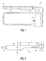
- a typical IVT intracavity probe 10 is shown in FIGURE 1 . This probe includes a shaft portion 12 of about 16,7 cm (6.6 inches) in length and 2,54 cm (one inch) in diameter which is inserted into a body cavity. The ultrasound transducer is located in the distal tip 14 of the shaft. The probe is grasped and manipulated by a handle 16 during use.
- a strain relief 18 for a cable 20 which extend about 91,4 cm - 213,4 cm (3-7 feet) and terminates at a connector 22 which couples the probe to an ultrasound system.
- a typical IVT probe may have a shaft and handle which is 30,5 cm (12 inches) in length and weigh about 1361 grams (48 ounces) including the cable 20 and the connector 22.
- ultrasound systems have been introduced with three dimensional (3D) imaging capability and intracavity probes have been designed to perform 3D imaging.
- this is done by replacing the array transducer which is statically affixed in the distal tip with an array transducer which can be oscillated rapidly in the elevation direction. This oscillation will sweep the image plane being scanned through a volumetric region, acquiring multiple adjacent planar images which can be rendered into a three dimensional image.
- the oscillating array transducer of the 3D probe must be contained within a fluid through which it can oscillate and which is highly transmissive of ultrasound.
- this fluid will be a water or oil-based solution such as a mineral oil.
- the fluid is preferably biocompatible so as not to injure or irritate the tissues of the patient in the event of leakage.
- These mechanically oscillating 3D array probes will generally house the motor for the oscillation drive within the handle of the probe, thereby keeping it outside the body of the patient. This motor location then mandates a fluid compartment for the oscillating mechanism and transducer which extends through most of or all of the shaft and distal tip of the probe.
- the fluid will comprise a large portion of the weight of the probe which is located in the shaft of the probe, causing the center of gravity of the probe to be forward of the handle and in the shaft of the probe. This imbalance makes the intracavity probe unwieldy and difficult to manipulate easily.
- US 5,762,066 describes an intracavity probe with a rotatable transducer member in the distal end of a housing.
- a window is closed with a membrane.
- a fluid reservoir extending from the distal end throughout the handle is enclosed in the probe housing, provided with a pressurizing piston at the proximal end of the handle system to adjust pressure of the coupling fluid in the reservoir against the membrane.
- the invention is defined by claim 1.
- a 3D intracavity probe includes an array transducer in the distal tip which is swept to scan a volumetric region.
- the array transducer is swept by motor which is located in the handle of the probe.
- the array transducer is contained within a fluid chamber located at the distal tip of the probe and requiring less than 10 cm 3 (cc) of fluid.
- the array transducer is mounted on an array mount made of a low mass material and displacing space within the chamber which otherwise would be filled with fluid, thereby reducing the fluid volume of the chamber.
- the shaft and shaft components, except for critical wear surfaces of the array drive mechanism, are also made of low mass materials such as plastics and aluminum. Accordingly, the weight of the probe is less than two-thirds of the weight of prior art 3D intracavity probes.
- the probe 30 includes a handle section 36 by which the user holds the handle for manipulation during use.
- a strain relief 18 for the probe cable (not shown).
- Extending from the forward end of the handle 36 is the shaft 32 of the probe which terminates in a dome-shaped acoustic window 34 at the distal end through which ultrasound is transmitted and received during imaging.
- Contained within the distal end of the shaft is a transducer mount assembly 40 which is also shown in the cross-sectional view of the shaft of FIGURE 3 and in the uncovered view of FIGURE 4 .
- a convex curved array transducer 46 is attached to a transducer cradle 48 at the distal end of the assembly 40.
- the transducer cradle 48 is pivotally mounted by its pivot axis 49 to be rocked back and forth in the distal end of the probe and thereby sweep an image plane through a volumetric region in front of the probe.
- the transducer cradle 48 is rocked by an oscillating drive shaft 50 which extends from a motor and position sensor 60 in the handle 36 to the transducer mount assembly 40.
- the drive shaft 50 extends through an isolation tube 52 in the shaft which serves to isolate the moving drive shaft from the electrical conductors and volume compensation balloon 44 located in the shaft proximal the transducer mount assembly 40.
- the drive shaft 50 rocks the cradle by means of two mating bevel gears 54, one at the end of the drive shaft 50 and another on the transducer cradle 48.
- the motor alternately drives the drive shaft 50 in one direction of rotation and then the other, which alternately rocks the transducer cradle 48 in one direction and then the other, which sweeps the image plane of the transducer array 46 back and forth through the volumetric region in front of the distal end of the probe.
- the echo signals acquired by the transducer array 46 are beamformed, detected, and rendered by the ultrasound system to form a three dimensional image of the volumetric region scanned by the probe.
- the array transducer 46 is surrounded by a liquid which is transmissive of ultrasound and closely matches the acoustic impedance of the body which is approximately that of water.
- Water-based, oil-based, and synthetic polymeric liquids may be used. In a constructed embodiment silicone oil is used.
- only a small amount of liquid is required in the shaft 32 because the weight of the liquid can contribute significantly to the overall weight of the shaft.
- the entire shaft is filled with liquid, adding substantial weight to the shaft and causing the center of gravity of the handle and shaft to be located in the shaft.
- Other prior art probes have used sizeable elastomeric bags of liquid for the liquid bath of the transducer array. These embodiments also locate the center of gravity of the probe in the shaft, which makes the probe ungainly and difficult to maneuver easily.
- the liquid used in such embodiments can approach 50 cm 3 (cc), for instance, adding its weight to the probe shaft at the distal end.
- the majority of the liquid bath for the transducer array is contained within the transducer mount assembly 40.
- the only liquid located to the rear of the back surface 42 of the transducer mount assembly 40 is the small amount of the volume compensation balloon 44.
- the total amount of liquid in the shaft of the probe is 6.3 cm 3 (cc), of which 95% is contained within the transducer mount assembly 40.
- Only 0.3 cm 3 (cc) of liquid is contained within the volume compensation balloon 44, which can be kept to a small volume of liquid due to the low overall volume of liquid.
- the length of the shaft 32 was 19,1 cm (7.5 inches) from the handle to the distal tip (dimension A in FIGURE 2 ).
- the transducer mount assembly 40 is contained within the distal 3,8 cm (1.5 inches) of that length (dimension B in FIGURE 2 ). Thus, there is only 6 cm 3 (cc) of liquid in the forward half of the probe shaft 32, and only 6.3 cm 3 (cc) of liquid in the entire shaft. Ninety-five percent of the liquid is in close proximity to the transducer array, located as it is in the distal 20% of the probe shaft. With so little liquid in the shaft and so little liquid in the forward half of the probe shaft, and the motor located in the handle, the center of gravity 62 of the probe handle and shaft is located in the handle, 2,54 cm (a full inch) behind the handle/shaft interface (dimension C in FIGURE 2 ). With the center of gravity located in the handle the probe is much easier and more comfortable to manipulate during use.
- the embodiment of FIGURES 3 and 4 employ additional measures to reduce the amount of liquid and the weight of the probe shaft 32.
- Only critical wear surfaces within the shaft 32, such as the drive shaft 50, the gears 54, and pivot points for the transducer cradle are made of stainless steel. Selected fasteners and fittings are also made of stainless steel. Other components within the shaft are made of lighter materials with a density lighter than that of stainless steel.
- the transducer cradle 48 is made of three pieces of aluminum and is tapered on the sides which are the leading edges as the cradle travels through the liquid. The tapering on either side causes the cradle to move more easily through the liquid with less resistance.
- the space behind the transducer array and backing is not hollow but is filled so as to displace volume that would otherwise be occupied by liquid, further reducing the liquid needed in the distal end of the probe.
- the main body of the transducer mount assembly 40 is also made of aluminum, as is the isolation tube 52.
- the volume compensation balloon 44 is made of a thin plastic.
- the transducer array and its backing are made of material customarily used for those purposes such as piezoelectric ceramic and epoxy. This use of lightweight materials enables a constructed embodiment of the present invention including the probe shaft and handle to weigh only 250 grams, compared to the 400 gram weights of prior art probes.
Landscapes
- Life Sciences & Earth Sciences (AREA)
- Health & Medical Sciences (AREA)
- Biomedical Technology (AREA)
- Biophysics (AREA)
- Nuclear Medicine, Radiotherapy & Molecular Imaging (AREA)
- Pathology (AREA)
- Radiology & Medical Imaging (AREA)
- Engineering & Computer Science (AREA)
- Physics & Mathematics (AREA)
- Heart & Thoracic Surgery (AREA)
- Medical Informatics (AREA)
- Molecular Biology (AREA)
- Surgery (AREA)
- Animal Behavior & Ethology (AREA)
- General Health & Medical Sciences (AREA)
- Public Health (AREA)
- Veterinary Medicine (AREA)
- Ultra Sonic Daignosis Equipment (AREA)
Description
- This invention relates to medical diagnostic imaging systems and, in particular, to intracavity probes for three dimensional imaging for ultrasonic diagnostic imaging systems.
- Intracavity ultrasound probes have been in use for many years for imaging the body from within the body. By imaging from within the body internal organs can be imaged more directly without the need to transmit ultrasound waves through intervening tissue and body structure. For example, transesophageal probes can image the heart and abdominal organs from the esophagus or stomach and avoid the need to send and receive ultrasound through or around the ribs. The present invention relates to intracavity probes inserted in the vagina (IVT probes) or rectum (ICT probes) to image the cervix, uterus, or prostate.
- In the past, IVT and ICT probes have scanned a two dimensional image region from within the body. This could be done with an array transducer or oscillating single crystal transducer which would scan a sector-shaped area of the body. By curving the elements of an array transducer completely around the distal tip region of the probe, sectors approximating 180° could be scanned. A typical IVT intracavity probe 10 is shown in
FIGURE 1 . This probe includes ashaft portion 12 of about 16,7 cm (6.6 inches) in length and 2,54 cm (one inch) in diameter which is inserted into a body cavity. The ultrasound transducer is located in thedistal tip 14 of the shaft. The probe is grasped and manipulated by ahandle 16 during use. At the end of the handle is astrain relief 18 for acable 20 which extend about 91,4 cm - 213,4 cm (3-7 feet) and terminates at aconnector 22 which couples the probe to an ultrasound system. A typical IVT probe may have a shaft and handle which is 30,5 cm (12 inches) in length and weigh about 1361 grams (48 ounces) including thecable 20 and theconnector 22. - In recent years ultrasound systems have been introduced with three dimensional (3D) imaging capability and intracavity probes have been designed to perform 3D imaging. Generally this is done by replacing the array transducer which is statically affixed in the distal tip with an array transducer which can be oscillated rapidly in the elevation direction. This oscillation will sweep the image plane being scanned through a volumetric region, acquiring multiple adjacent planar images which can be rendered into a three dimensional image. However, as was the case with earlier oscillating single crystal or annular array transducers, the oscillating array transducer of the 3D probe must be contained within a fluid through which it can oscillate and which is highly transmissive of ultrasound. Generally this fluid will be a water or oil-based solution such as a mineral oil. The fluid is preferably biocompatible so as not to injure or irritate the tissues of the patient in the event of leakage.
- These mechanically oscillating 3D array probes will generally house the motor for the oscillation drive within the handle of the probe, thereby keeping it outside the body of the patient. This motor location then mandates a fluid compartment for the oscillating mechanism and transducer which extends through most of or all of the shaft and distal tip of the probe. The fluid will comprise a large portion of the weight of the probe which is located in the shaft of the probe, causing the center of gravity of the probe to be forward of the handle and in the shaft of the probe. This imbalance makes the intracavity probe unwieldy and difficult to manipulate easily.
-
US 5,762,066 describes an intracavity probe with a rotatable transducer member in the distal end of a housing. A window is closed with a membrane. A fluid reservoir extending from the distal end throughout the handle is enclosed in the probe housing, provided with a pressurizing piston at the proximal end of the handle system to adjust pressure of the coupling fluid in the reservoir against the membrane. - It would be desirable to reduce the forward weight and balance of the probe so that the 3D intracavity probe is easier to manipulate during a diagnostic procedure.
- The invention is defined by claim 1.
- In accordance with the principles of the present invention a 3D intracavity probe includes an array transducer in the distal tip which is swept to scan a volumetric region. The array transducer is swept by motor which is located in the handle of the probe. The array transducer is contained within a fluid chamber located at the distal tip of the probe and requiring less than 10 cm3 (cc) of fluid. As a result, the center of gravity of the shaft and handle is located in the handle and not the shaft, making the probe easier and more comfortable to hold and manipulate during use.
- In accordance with further aspects of the present invention, the array transducer is mounted on an array mount made of a low mass material and displacing space within the chamber which otherwise would be filled with fluid, thereby reducing the fluid volume of the chamber. The shaft and shaft components, except for critical wear surfaces of the array drive mechanism, are also made of low mass materials such as plastics and aluminum. Accordingly, the weight of the probe is less than two-thirds of the weight of prior art 3D intracavity probes.
- In the drawings:
-
FIGURE 1 illustrates a typical intracavity ultrasound probe of the prior art. -
FIGURE 2 illustrates a side view of an intracavity probe for three dimensional imaging of the present invention. -
FIGURE 3 is a side cross-sectional view of a 3D intracavity probe of the present invention. -
FIGURE 4 is a perspective view of the tip assembly of a 3D intracavity probe of the present invention. - Referring now to
FIGURE 2 , anintracavity ultrasound probe 30 of the present invention is shown. Theprobe 30 includes ahandle section 36 by which the user holds the handle for manipulation during use. At the rear of the handle is astrain relief 18 for the probe cable (not shown). Extending from the forward end of thehandle 36 is theshaft 32 of the probe which terminates in a dome-shapedacoustic window 34 at the distal end through which ultrasound is transmitted and received during imaging. Contained within the distal end of the shaft is atransducer mount assembly 40 which is also shown in the cross-sectional view of the shaft ofFIGURE 3 and in the uncovered view ofFIGURE 4 . A convexcurved array transducer 46 is attached to atransducer cradle 48 at the distal end of theassembly 40. Thetransducer cradle 48 is pivotally mounted by itspivot axis 49 to be rocked back and forth in the distal end of the probe and thereby sweep an image plane through a volumetric region in front of the probe. Thetransducer cradle 48 is rocked by an oscillatingdrive shaft 50 which extends from a motor andposition sensor 60 in thehandle 36 to thetransducer mount assembly 40. Thedrive shaft 50 extends through anisolation tube 52 in the shaft which serves to isolate the moving drive shaft from the electrical conductors andvolume compensation balloon 44 located in the shaft proximal thetransducer mount assembly 40. Thedrive shaft 50 rocks the cradle by means of twomating bevel gears 54, one at the end of thedrive shaft 50 and another on thetransducer cradle 48. The motor alternately drives thedrive shaft 50 in one direction of rotation and then the other, which alternately rocks thetransducer cradle 48 in one direction and then the other, which sweeps the image plane of thetransducer array 46 back and forth through the volumetric region in front of the distal end of the probe. The echo signals acquired by thetransducer array 46 are beamformed, detected, and rendered by the ultrasound system to form a three dimensional image of the volumetric region scanned by the probe. - Because ultrasonic energy does not efficiently pass through air, the
array transducer 46 is surrounded by a liquid which is transmissive of ultrasound and closely matches the acoustic impedance of the body which is approximately that of water. Water-based, oil-based, and synthetic polymeric liquids may be used. In a constructed embodiment silicone oil is used. In accordance with the principles of the present invention, only a small amount of liquid is required in theshaft 32 because the weight of the liquid can contribute significantly to the overall weight of the shaft. In some prior art probes the entire shaft is filled with liquid, adding substantial weight to the shaft and causing the center of gravity of the handle and shaft to be located in the shaft. Other prior art probes have used sizeable elastomeric bags of liquid for the liquid bath of the transducer array. These embodiments also locate the center of gravity of the probe in the shaft, which makes the probe ungainly and difficult to maneuver easily. The liquid used in such embodiments can approach 50 cm3 (cc), for instance, adding its weight to the probe shaft at the distal end. - In accordance with the principles of the present invention the majority of the liquid bath for the transducer array is contained within the
transducer mount assembly 40. The only liquid located to the rear of theback surface 42 of the transducer mount assembly 40 (seeFIGURE 2 ) is the small amount of thevolume compensation balloon 44. In a constructed embodiment the total amount of liquid in the shaft of the probe is 6.3 cm3 (cc), of which 95% is contained within thetransducer mount assembly 40. Only 0.3 cm3 (cc) of liquid is contained within thevolume compensation balloon 44, which can be kept to a small volume of liquid due to the low overall volume of liquid. In the constructed embodiment the length of theshaft 32 was 19,1 cm (7.5 inches) from the handle to the distal tip (dimension A inFIGURE 2 ). Thetransducer mount assembly 40 is contained within the distal 3,8 cm (1.5 inches) of that length (dimension B inFIGURE 2 ). Thus, there is only 6 cm3 (cc) of liquid in the forward half of theprobe shaft 32, and only 6.3 cm3 (cc) of liquid in the entire shaft. Ninety-five percent of the liquid is in close proximity to the transducer array, located as it is in the distal 20% of the probe shaft. With so little liquid in the shaft and so little liquid in the forward half of the probe shaft, and the motor located in the handle, the center ofgravity 62 of the probe handle and shaft is located in the handle, 2,54 cm (a full inch) behind the handle/shaft interface (dimension C inFIGURE 2 ). With the center of gravity located in the handle the probe is much easier and more comfortable to manipulate during use. - In addition to the small amount of fluid needed in the forward section of the shaft, the embodiment of
FIGURES 3 and4 employ additional measures to reduce the amount of liquid and the weight of theprobe shaft 32. Only critical wear surfaces within theshaft 32, such as thedrive shaft 50, thegears 54, and pivot points for the transducer cradle are made of stainless steel. Selected fasteners and fittings are also made of stainless steel. Other components within the shaft are made of lighter materials with a density lighter than that of stainless steel. Thetransducer cradle 48 is made of three pieces of aluminum and is tapered on the sides which are the leading edges as the cradle travels through the liquid. The tapering on either side causes the cradle to move more easily through the liquid with less resistance. The space behind the transducer array and backing is not hollow but is filled so as to displace volume that would otherwise be occupied by liquid, further reducing the liquid needed in the distal end of the probe. The main body of thetransducer mount assembly 40 is also made of aluminum, as is theisolation tube 52. Thevolume compensation balloon 44 is made of a thin plastic. The transducer array and its backing are made of material customarily used for those purposes such as piezoelectric ceramic and epoxy. This use of lightweight materials enables a constructed embodiment of the present invention including the probe shaft and handle to weigh only 250 grams, compared to the 400 gram weights of prior art probes.
Claims (19)
- An ultrasonic intracavity probe (30) for scanning a volumetric region from within the body comprising:a handle section (36) to be held during use of the probe (30); anda shaft section (32) having a distal end which is to be inserted into a body cavity during use of the probe (30);a pivotally mounted array transducer (46) located in the distal end of the shaft section (32);a motor (60) located in the handle section (36);a drive mechanism coupled to the motor (60) and the array transducer (46) which acts to move the array transducer (46) during scanning; anda liquid bath located in the distal end of the shaft section (32), a portion of which is located between the array transducer (46) and the distal end of the shaft section (32) during scanning, wherein the center of gravity of the probe (30) is located in the handle section (36); wherein a transducer mount assembly (40) is located in the distal end of the shaft section (38), the array transducer (46) being pivotally mounted to the transducer mount assembly (40);wherein the liquid bath is located within the transducer mount assembly (40);wherein the majority of the liquid bath is contained within the transducer mount assembly (40).
- The ultrasonic intracavity probe of Claim 1, wherein the transducer mount assembly (40) has a proximal termination within 7,62 cm (3 inches) of the distal end of the shaft section (32),
wherein 75% of the liquid bath is contained within the transducer mount assembly (40). - The ultrasonic intracavity probe of Claim 2, wherein the transducer mount assembly (40) has a proximal termination within 3,8 cm (1.5 inches) of the distal end of the shaft section (32).
- The ultrasonic intracavity probe of Claim 3, wherein 90% of the liquid bath is contained within the transducer mount assembly (40).
- The ultrasonic intracavity probe of Claim 1, wherein the liquid bath has a volume of less than 25 cm3 (cc) of liquid.
- The ultrasonic intracavity probe of Claim 5, wherein the liquid bath has a volume of less than 10 cm3 (cc) of liquid.
- The ultrasonic intracavity probe of Claim 6, wherein the liquid bath has a volume of approximately 6 cm3 (cc) of liquid.
- The ultrasonic intracavity probe of Claim 1, wherein 90% of the liquid bath is located in the most distal 25% of the length of the shaft section (32).
- The ultrasonic intracavity probe of Claim 8, wherein the liquid bath has a volume of less than 10 cm3 (cc) of liquid.
- The ultrasonic intracavity probe of Claim 1, wherein the transducer mount assembly (40) has a main body formed of a material which is lighter than stainless steel.
- The ultrasonic intracavity probe of Claim 10, wherein the array transducer (46) is pivotally mounted to the transducer mount assembly (40) by a transducer cradle (48),
wherein the transducer cradle (48) is made of a material which is lighter than stainless steel. - The ultrasonic intracavity probe of Claim 11, wherein the transducer cradle (48) includes a solid body located behind the array transducer (46) which displaces volume in the transducer mount assembly (40) that would otherwise be occupied by liquid.
- The ultrasonic intracavity probe of Claim 11, wherein the transducer cradle (48) is tapered so as to pass more easily through the liquid bath.
- The ultrasonic intracavity probe of Claim 10, wherein the transducer mount assembly (40) includes wear surfaces made of stainless steel.
- The ultrasonic intracavity probe of Claim 14, wherein the wear surfaces are part of the drive mechanism.
- The ultrasonic intracavity probe of Claim 10, wherein the weight of the probe (30) is less than 400 grams.
- The ultrasonic intracavity probe of Claim 16, wherein the weight of the probe (30) is less than 300 grams.
- The ultrasonic intracavity probe of Claim 17, wherein the weight of the probe (30) is approximately 250 grams.
- The ultrasonic intracavity probe of Claim 17, wherein the only components of the shaft section (32) which are made of a material at least equal to the density of stainless steel are components of the drive mechanism.
Applications Claiming Priority (2)
| Application Number | Priority Date | Filing Date | Title |
|---|---|---|---|
| US55932104P | 2004-04-02 | 2004-04-02 | |
| PCT/IB2005/050984 WO2005094689A1 (en) | 2004-04-02 | 2005-03-22 | Ultrasonic intracavity probe for 3d imaging |
Publications (2)
| Publication Number | Publication Date |
|---|---|
| EP1742580A1 EP1742580A1 (en) | 2007-01-17 |
| EP1742580B1 true EP1742580B1 (en) | 2012-10-24 |
Family
ID=34962002
Family Applications (1)
| Application Number | Title | Priority Date | Filing Date |
|---|---|---|---|
| EP05718545A Expired - Lifetime EP1742580B1 (en) | 2004-04-02 | 2005-03-22 | Ultrasonic intracavity probe for 3d imaging |
Country Status (5)
| Country | Link |
|---|---|
| US (1) | US9808221B2 (en) |
| EP (1) | EP1742580B1 (en) |
| JP (1) | JP4847442B2 (en) |
| CN (1) | CN100482174C (en) |
| WO (1) | WO2005094689A1 (en) |
Cited By (3)
| Publication number | Priority date | Publication date | Assignee | Title |
|---|---|---|---|---|
| WO2017076758A1 (en) | 2015-11-02 | 2017-05-11 | Koninklijke Philips N.V. | An ultrasound system for providing ultrasound images at variable frequencies of a volumetric region comprising an interferer analyzer |
| WO2018077962A1 (en) | 2016-10-27 | 2018-05-03 | Koninklijke Philips N.V. | An ultrasound system with a tissue type analyzer |
| EP3366221A1 (en) | 2017-02-28 | 2018-08-29 | Koninklijke Philips N.V. | An intelligent ultrasound system |
Families Citing this family (41)
| Publication number | Priority date | Publication date | Assignee | Title |
|---|---|---|---|---|
| US6618620B1 (en) | 2000-11-28 | 2003-09-09 | Txsonics Ltd. | Apparatus for controlling thermal dosing in an thermal treatment system |
| US8409099B2 (en) * | 2004-08-26 | 2013-04-02 | Insightec Ltd. | Focused ultrasound system for surrounding a body tissue mass and treatment method |
| US7918795B2 (en) | 2005-02-02 | 2011-04-05 | Gynesonics, Inc. | Method and device for uterine fibroid treatment |
| EP1960993B1 (en) | 2005-11-23 | 2016-11-02 | Insightec-Image Guided Treatment, Ltd. | Hierarchical switching in ultra-high density ultrasound array |
| US11259825B2 (en) | 2006-01-12 | 2022-03-01 | Gynesonics, Inc. | Devices and methods for treatment of tissue |
| US10595819B2 (en) | 2006-04-20 | 2020-03-24 | Gynesonics, Inc. | Ablation device with articulated imaging transducer |
| US20090018446A1 (en) * | 2007-07-10 | 2009-01-15 | Insightec, Ltd. | Transrectal ultrasound ablation probe |
| US8251908B2 (en) | 2007-10-01 | 2012-08-28 | Insightec Ltd. | Motion compensated image-guided focused ultrasound therapy system |
| US8088072B2 (en) | 2007-10-12 | 2012-01-03 | Gynesonics, Inc. | Methods and systems for controlled deployment of needles in tissue |
| JP5346182B2 (en) * | 2008-07-30 | 2013-11-20 | 富士フイルム株式会社 | Intracavity ultrasound probe |
| EP2163218A1 (en) * | 2008-09-16 | 2010-03-17 | Osyris Medical | Device for treating part of a human or animal body comprising an instrument for dispensing and/or an instrument for locally sucking up treatment doses and means for controlling dosimetry |
| US8425424B2 (en) | 2008-11-19 | 2013-04-23 | Inightee Ltd. | Closed-loop clot lysis |
| US8262574B2 (en) | 2009-02-27 | 2012-09-11 | Gynesonics, Inc. | Needle and tine deployment mechanism |
| US8617073B2 (en) | 2009-04-17 | 2013-12-31 | Insightec Ltd. | Focusing ultrasound into the brain through the skull by utilizing both longitudinal and shear waves |
| WO2010129773A1 (en) * | 2009-05-07 | 2010-11-11 | Aloka Co., Ltd. | Ultrasound systems and methods for orthopedic applications |
| US20100324418A1 (en) * | 2009-06-23 | 2010-12-23 | Essa El-Aklouk | Ultrasound transducer |
| US9623266B2 (en) | 2009-08-04 | 2017-04-18 | Insightec Ltd. | Estimation of alignment parameters in magnetic-resonance-guided ultrasound focusing |
| US9177543B2 (en) | 2009-08-26 | 2015-11-03 | Insightec Ltd. | Asymmetric ultrasound phased-array transducer for dynamic beam steering to ablate tissues in MRI |
| KR20110032122A (en) * | 2009-09-22 | 2011-03-30 | 주식회사 메디슨 | 3D probe device |
| EP2489034B1 (en) | 2009-10-14 | 2016-11-30 | Insightec Ltd. | Mapping ultrasound transducers |
| US8932237B2 (en) | 2010-04-28 | 2015-01-13 | Insightec, Ltd. | Efficient ultrasound focusing |
| US9852727B2 (en) | 2010-04-28 | 2017-12-26 | Insightec, Ltd. | Multi-segment ultrasound transducers |
| US9981148B2 (en) | 2010-10-22 | 2018-05-29 | Insightec, Ltd. | Adaptive active cooling during focused ultrasound treatment |
| JP6042212B2 (en) * | 2011-02-01 | 2016-12-14 | コニカミノルタ株式会社 | Intracavity ultrasound probe |
| US12402802B2 (en) | 2011-08-31 | 2025-09-02 | Insightec Ltd. | Avoiding MRI-interference with co-existing systems |
| CN102415906B (en) * | 2011-09-06 | 2013-10-16 | 深圳市开立科技有限公司 | Tri-plane ultrasonic probe |
| US9861336B2 (en) | 2012-09-07 | 2018-01-09 | Gynesonics, Inc. | Methods and systems for controlled deployment of needle structures in tissue |
| WO2014059315A1 (en) * | 2012-10-12 | 2014-04-17 | Muffin Incorporated | Reciprocating internal ultrasound transducer assembly |
| WO2014150376A1 (en) | 2013-03-15 | 2014-09-25 | Muffin Incorporated | Internal ultrasound assembly fluid seal |
| WO2015012420A1 (en) * | 2013-07-23 | 2015-01-29 | 알피니언메디칼시스템 주식회사 | Ultrasonic probe |
| US11317892B2 (en) | 2015-08-12 | 2022-05-03 | Muffin Incorporated | Over-the-wire ultrasound system with torque-cable driven rotary transducer |
| JP6907193B2 (en) * | 2015-09-10 | 2021-07-21 | コーニンクレッカ フィリップス エヌ ヴェKoninklijke Philips N.V. | Ultrasonic system with wide depth and detailed view |
| CN105662468A (en) * | 2016-02-29 | 2016-06-15 | 深圳市索诺瑞科技有限公司 | Mechanical scanning probe with coupling solution serving as focusing material |
| WO2018089523A1 (en) | 2016-11-11 | 2018-05-17 | Gynesonics, Inc. | Controlled treatment of tissue and dynamic interaction with, and comparison of, tissue and/or treatment data |
| JP2018075322A (en) * | 2016-11-12 | 2018-05-17 | 株式会社クレイツ | Ultrasonic/minute-current combined apparatus for skin care |
| CA3043490A1 (en) | 2016-11-14 | 2018-05-17 | Gynesonics, Inc. | Methods and systems for real-time planning and monitoring of ablation needle deployment in tissue |
| CN110831506A (en) | 2017-05-04 | 2020-02-21 | 杰尼索尼克斯公司 | Methods for monitoring ablation progress with Doppler ultrasound |
| WO2020075574A1 (en) | 2018-10-11 | 2020-04-16 | 富士フイルム株式会社 | Ultrasonic probe |
| WO2023073424A1 (en) * | 2021-10-28 | 2023-05-04 | VisOvum Ltd. | Ultrasonic endocavitary imaging system and method |
| US20230190240A1 (en) * | 2021-12-22 | 2023-06-22 | GE Precision Healthcare LLC | Passive cooling for medical imaging probes |
| FR3142339B1 (en) | 2022-11-30 | 2024-10-11 | Echopen Factory | MULTI-PURPOSE ULTRASOUND PROBE WITH MULTIPLE SINGLE-ELEMENT TRANSDUCERS WITH OSCILLATING MECHANICAL SCANNING |
Citations (1)
| Publication number | Priority date | Publication date | Assignee | Title |
|---|---|---|---|---|
| US5762066A (en) * | 1992-02-21 | 1998-06-09 | Ths International, Inc. | Multifaceted ultrasound transducer probe system and methods for its use |
Family Cites Families (35)
| Publication number | Priority date | Publication date | Assignee | Title |
|---|---|---|---|---|
| SE388123B (en) * | 1974-08-29 | 1976-09-27 | Svedia Dental Ind Ab | CERVICAL DILATATION VIBRATOR |
| JPH0763468B2 (en) * | 1986-01-17 | 1995-07-12 | オリンパス光学工業株式会社 | Ultrasound endoscopy |
| JPS63115546A (en) * | 1986-10-31 | 1988-05-20 | 松下電器産業株式会社 | Ultrasonic probe |
| JP2618934B2 (en) * | 1987-11-19 | 1997-06-11 | オリンパス光学工業株式会社 | Ultrasound endoscope |
| CN87207131U (en) * | 1987-06-03 | 1988-02-03 | 上海交通大学 | Mechanical scanning ultrasonic diagnostic instrument probe |
| US4917096A (en) * | 1987-11-25 | 1990-04-17 | Laboratory Equipment, Corp. | Portable ultrasonic probe |
| JPH0255050A (en) * | 1988-08-22 | 1990-02-23 | Toshiba Corp | Mechanical scanning type ultrasonic probe |
| JPH0722583B2 (en) | 1990-04-05 | 1995-03-15 | 松下電器産業株式会社 | Mechanical scanning ultrasonic probe |
| JP2606433B2 (en) * | 1990-10-08 | 1997-05-07 | 富士写真光機株式会社 | Mechanical radial scanning ultrasonic diagnostic equipment |
| US5178150A (en) * | 1991-02-25 | 1993-01-12 | Silverstein Fred E | Miniature ultrasound imaging probe |
| JPH0542151A (en) | 1991-08-16 | 1993-02-23 | Olympus Optical Co Ltd | Ultrasonic diagnostic device |
| US5993389A (en) * | 1995-05-22 | 1999-11-30 | Ths International, Inc. | Devices for providing acoustic hemostasis |
| US5383460A (en) * | 1992-10-05 | 1995-01-24 | Cardiovascular Imaging Systems, Inc. | Method and apparatus for ultrasound imaging and atherectomy |
| JPH06209937A (en) * | 1993-01-21 | 1994-08-02 | Olympus Optical Co Ltd | Ultrasonic probe |
| DE4420221C2 (en) | 1994-06-06 | 1996-10-31 | Windi Winderlich Gmbh | Process for the production of cellulose fiber material from vegetable substrate containing calcium pectinate |
| DE4420220C2 (en) * | 1994-06-06 | 1998-10-15 | Arno Schnorrenberg | Ultrasound head carrier |
| US5722964A (en) * | 1995-03-13 | 1998-03-03 | Atrium Medical Corporation | Filtered blood collection device |
| JPH09135908A (en) * | 1995-11-17 | 1997-05-27 | Aloka Co Ltd | Ultrasonic diagnosis treatment system |
| US5740804A (en) * | 1996-10-18 | 1998-04-21 | Esaote, S.P.A | Multipanoramic ultrasonic probe |
| US5846205A (en) * | 1997-01-31 | 1998-12-08 | Acuson Corporation | Catheter-mounted, phased-array ultrasound transducer with improved imaging |
| JP3707209B2 (en) | 1997-07-17 | 2005-10-19 | 住友電気工業株式会社 | Optical fiber preform manufacturing method |
| JP2002516586A (en) | 1997-06-23 | 2002-06-04 | ティーエイチエス インターナショナル,インコーポレイテッド | Method and apparatus for providing acoustic hemostasis |
| US6315710B1 (en) * | 1997-07-21 | 2001-11-13 | St. Croix Medical, Inc. | Hearing system with middle ear transducer mount |
| JPH11206778A (en) * | 1998-01-27 | 1999-08-03 | Olympus Optical Co Ltd | Endoceliac ultrasonic wave probe |
| US6039694A (en) * | 1998-06-25 | 2000-03-21 | Sonotech, Inc. | Coupling sheath for ultrasound transducers |
| JP2001154098A (en) * | 1999-11-30 | 2001-06-08 | Mitsutoyo Corp | Image probe |
| JP2001224595A (en) * | 1999-12-08 | 2001-08-21 | Olympus Optical Co Ltd | Ultrasonic probe for microscopic operation |
| US6361500B1 (en) * | 2000-02-07 | 2002-03-26 | Scimed Life Systems, Inc. | Three transducer catheter |
| US6394747B1 (en) | 2000-06-21 | 2002-05-28 | Varian, Inc. | Molecular drag vacuum pumps |
| JP2002301081A (en) * | 2001-04-06 | 2002-10-15 | Matsushita Electric Ind Co Ltd | Ultrasonic vibrator drive motor and ultrasonic diagnostic apparatus using the motor |
| US6592520B1 (en) | 2001-07-31 | 2003-07-15 | Koninklijke Philips Electronics N.V. | Intravascular ultrasound imaging apparatus and method |
| JP2003164450A (en) * | 2001-11-26 | 2003-06-10 | Ge Medical Systems Global Technology Co Llc | Ultrasonic probe |
| JP2003230568A (en) * | 2002-02-08 | 2003-08-19 | Olympus Optical Co Ltd | Ultrasonic treating instrument |
| US6784600B2 (en) * | 2002-05-01 | 2004-08-31 | Koninklijke Philips Electronics N.V. | Ultrasonic membrane transducer for an ultrasonic diagnostic probe |
| US8409102B2 (en) * | 2010-08-31 | 2013-04-02 | General Electric Company | Multi-focus ultrasound system and method |
-
2005
- 2005-03-22 US US10/599,306 patent/US9808221B2/en active Active
- 2005-03-22 WO PCT/IB2005/050984 patent/WO2005094689A1/en not_active Ceased
- 2005-03-22 CN CNB2005800108208A patent/CN100482174C/en not_active Expired - Lifetime
- 2005-03-22 JP JP2007505692A patent/JP4847442B2/en not_active Expired - Fee Related
- 2005-03-22 EP EP05718545A patent/EP1742580B1/en not_active Expired - Lifetime
Patent Citations (1)
| Publication number | Priority date | Publication date | Assignee | Title |
|---|---|---|---|---|
| US5762066A (en) * | 1992-02-21 | 1998-06-09 | Ths International, Inc. | Multifaceted ultrasound transducer probe system and methods for its use |
Cited By (5)
| Publication number | Priority date | Publication date | Assignee | Title |
|---|---|---|---|---|
| WO2017076758A1 (en) | 2015-11-02 | 2017-05-11 | Koninklijke Philips N.V. | An ultrasound system for providing ultrasound images at variable frequencies of a volumetric region comprising an interferer analyzer |
| WO2018077962A1 (en) | 2016-10-27 | 2018-05-03 | Koninklijke Philips N.V. | An ultrasound system with a tissue type analyzer |
| EP3366221A1 (en) | 2017-02-28 | 2018-08-29 | Koninklijke Philips N.V. | An intelligent ultrasound system |
| WO2018158283A1 (en) | 2017-02-28 | 2018-09-07 | Koninklijke Philips N.V. | An intelligent ultrasound system |
| EP3763294A1 (en) | 2017-02-28 | 2021-01-13 | Koninklijke Philips N.V. | An intelligent ultrasound system |
Also Published As
| Publication number | Publication date |
|---|---|
| CN1937963A (en) | 2007-03-28 |
| EP1742580A1 (en) | 2007-01-17 |
| JP4847442B2 (en) | 2011-12-28 |
| US20080228081A1 (en) | 2008-09-18 |
| US9808221B2 (en) | 2017-11-07 |
| WO2005094689A1 (en) | 2005-10-13 |
| CN100482174C (en) | 2009-04-29 |
| JP2007530206A (en) | 2007-11-01 |
Similar Documents
| Publication | Publication Date | Title |
|---|---|---|
| US9808221B2 (en) | Ultrasonic intracavity probe for 3D imaging | |
| US11484289B2 (en) | Probe for ultrasonic diagnostic apparatus | |
| JP4004396B2 (en) | Ultrasonic transducer | |
| JP6661372B2 (en) | Reciprocating internal ultrasonic transducer assembly | |
| US10327735B2 (en) | Portable ultrasonic probe having a folder part | |
| CN101106944A (en) | Compression member, ultrasonic probe, and ultrasonic diagnostic device | |
| KR20110137829A (en) | Universal Multi-Aperture Medical Ultrasound Probe | |
| EP2648624B1 (en) | Imaging transducer probe | |
| US7484412B2 (en) | Ultrasound probe with multiple fluid chambers | |
| EP3028643B1 (en) | Ultrasound probe having rotatable transducer array for improved field of view and ultrasound diagnostic imaging system having the same | |
| US7588540B2 (en) | Ultrasonic probe for scanning a volume | |
| De Luca et al. | An educational overview of ultrasound probe types and their fields of application | |
| US8021305B2 (en) | Ultrasound probe, ultrasonograph, and ultrasonography | |
| KR102171257B1 (en) | Ultrasonic probe | |
| JPH10272134A (en) | Ultrasonic probe | |
| JPS6230012B2 (en) | ||
| JP3631416B2 (en) | Ultrasonic probe | |
| JP2001178727A (en) | Ultrasonic probe | |
| CN116421225A (en) | Ultrasonic probe and ultrasonic diagnostic apparatus | |
| JPH07275245A (en) | Ultrasonic probe for bronchus | |
| JPH05161651A (en) | Ultrasonic probe for inside of coelom | |
| JP2006006827A (en) | Attachment for ultrasonic probe, intravaginal ultrasonic probe and ultrasonic diagnostic apparatus | |
| JPS6139815B2 (en) | ||
| JP2006081845A (en) | Ultrasonic capsule | |
| JP2001299757A (en) | Ultrasonic probe |
Legal Events
| Date | Code | Title | Description |
|---|---|---|---|
| PUAI | Public reference made under article 153(3) epc to a published international application that has entered the european phase |
Free format text: ORIGINAL CODE: 0009012 |
|
| 17P | Request for examination filed |
Effective date: 20061102 |
|
| AK | Designated contracting states |
Kind code of ref document: A1 Designated state(s): AT BE BG CH CY CZ DE DK EE ES FI FR GB GR HU IE IS IT LI LT LU MC NL PL PT RO SE SI SK TR |
|
| DAX | Request for extension of the european patent (deleted) | ||
| 17Q | First examination report despatched |
Effective date: 20100729 |
|
| GRAP | Despatch of communication of intention to grant a patent |
Free format text: ORIGINAL CODE: EPIDOSNIGR1 |
|
| GRAS | Grant fee paid |
Free format text: ORIGINAL CODE: EPIDOSNIGR3 |
|
| GRAA | (expected) grant |
Free format text: ORIGINAL CODE: 0009210 |
|
| AK | Designated contracting states |
Kind code of ref document: B1 Designated state(s): AT BE BG CH CY CZ DE DK EE ES FI FR GB GR HU IE IS IT LI LT LU MC NL PL PT RO SE SI SK TR |
|
| REG | Reference to a national code |
Ref country code: GB Ref legal event code: FG4D |
|
| REG | Reference to a national code |
Ref country code: CH Ref legal event code: EP |
|
| REG | Reference to a national code |
Ref country code: AT Ref legal event code: REF Ref document number: 580456 Country of ref document: AT Kind code of ref document: T Effective date: 20121115 |
|
| REG | Reference to a national code |
Ref country code: IE Ref legal event code: FG4D |
|
| REG | Reference to a national code |
Ref country code: DE Ref legal event code: R096 Ref document number: 602005036663 Country of ref document: DE Effective date: 20121220 |
|
| REG | Reference to a national code |
Ref country code: DE Ref legal event code: R084 Ref document number: 602005036663 Country of ref document: DE Effective date: 20121208 |
|
| REG | Reference to a national code |
Ref country code: AT Ref legal event code: MK05 Ref document number: 580456 Country of ref document: AT Kind code of ref document: T Effective date: 20121024 |
|
| REG | Reference to a national code |
Ref country code: NL Ref legal event code: VDEP Effective date: 20121024 |
|
| PG25 | Lapsed in a contracting state [announced via postgrant information from national office to epo] |
Ref country code: FI Free format text: LAPSE BECAUSE OF FAILURE TO SUBMIT A TRANSLATION OF THE DESCRIPTION OR TO PAY THE FEE WITHIN THE PRESCRIBED TIME-LIMIT Effective date: 20121024 Ref country code: IS Free format text: LAPSE BECAUSE OF FAILURE TO SUBMIT A TRANSLATION OF THE DESCRIPTION OR TO PAY THE FEE WITHIN THE PRESCRIBED TIME-LIMIT Effective date: 20130224 Ref country code: SE Free format text: LAPSE BECAUSE OF FAILURE TO SUBMIT A TRANSLATION OF THE DESCRIPTION OR TO PAY THE FEE WITHIN THE PRESCRIBED TIME-LIMIT Effective date: 20121024 Ref country code: NL Free format text: LAPSE BECAUSE OF FAILURE TO SUBMIT A TRANSLATION OF THE DESCRIPTION OR TO PAY THE FEE WITHIN THE PRESCRIBED TIME-LIMIT Effective date: 20121024 Ref country code: ES Free format text: LAPSE BECAUSE OF FAILURE TO SUBMIT A TRANSLATION OF THE DESCRIPTION OR TO PAY THE FEE WITHIN THE PRESCRIBED TIME-LIMIT Effective date: 20130204 |
|
| PG25 | Lapsed in a contracting state [announced via postgrant information from national office to epo] |
Ref country code: PL Free format text: LAPSE BECAUSE OF FAILURE TO SUBMIT A TRANSLATION OF THE DESCRIPTION OR TO PAY THE FEE WITHIN THE PRESCRIBED TIME-LIMIT Effective date: 20121024 Ref country code: SI Free format text: LAPSE BECAUSE OF FAILURE TO SUBMIT A TRANSLATION OF THE DESCRIPTION OR TO PAY THE FEE WITHIN THE PRESCRIBED TIME-LIMIT Effective date: 20121024 Ref country code: GR Free format text: LAPSE BECAUSE OF FAILURE TO SUBMIT A TRANSLATION OF THE DESCRIPTION OR TO PAY THE FEE WITHIN THE PRESCRIBED TIME-LIMIT Effective date: 20130125 Ref country code: CY Free format text: LAPSE BECAUSE OF FAILURE TO SUBMIT A TRANSLATION OF THE DESCRIPTION OR TO PAY THE FEE WITHIN THE PRESCRIBED TIME-LIMIT Effective date: 20121024 Ref country code: PT Free format text: LAPSE BECAUSE OF FAILURE TO SUBMIT A TRANSLATION OF THE DESCRIPTION OR TO PAY THE FEE WITHIN THE PRESCRIBED TIME-LIMIT Effective date: 20130225 Ref country code: BE Free format text: LAPSE BECAUSE OF FAILURE TO SUBMIT A TRANSLATION OF THE DESCRIPTION OR TO PAY THE FEE WITHIN THE PRESCRIBED TIME-LIMIT Effective date: 20121024 |
|
| PG25 | Lapsed in a contracting state [announced via postgrant information from national office to epo] |
Ref country code: AT Free format text: LAPSE BECAUSE OF FAILURE TO SUBMIT A TRANSLATION OF THE DESCRIPTION OR TO PAY THE FEE WITHIN THE PRESCRIBED TIME-LIMIT Effective date: 20121024 |
|
| PG25 | Lapsed in a contracting state [announced via postgrant information from national office to epo] |
Ref country code: EE Free format text: LAPSE BECAUSE OF FAILURE TO SUBMIT A TRANSLATION OF THE DESCRIPTION OR TO PAY THE FEE WITHIN THE PRESCRIBED TIME-LIMIT Effective date: 20121024 Ref country code: CZ Free format text: LAPSE BECAUSE OF FAILURE TO SUBMIT A TRANSLATION OF THE DESCRIPTION OR TO PAY THE FEE WITHIN THE PRESCRIBED TIME-LIMIT Effective date: 20121024 Ref country code: SK Free format text: LAPSE BECAUSE OF FAILURE TO SUBMIT A TRANSLATION OF THE DESCRIPTION OR TO PAY THE FEE WITHIN THE PRESCRIBED TIME-LIMIT Effective date: 20121024 Ref country code: DK Free format text: LAPSE BECAUSE OF FAILURE TO SUBMIT A TRANSLATION OF THE DESCRIPTION OR TO PAY THE FEE WITHIN THE PRESCRIBED TIME-LIMIT Effective date: 20121024 Ref country code: BG Free format text: LAPSE BECAUSE OF FAILURE TO SUBMIT A TRANSLATION OF THE DESCRIPTION OR TO PAY THE FEE WITHIN THE PRESCRIBED TIME-LIMIT Effective date: 20130124 |
|
| PG25 | Lapsed in a contracting state [announced via postgrant information from national office to epo] |
Ref country code: RO Free format text: LAPSE BECAUSE OF FAILURE TO SUBMIT A TRANSLATION OF THE DESCRIPTION OR TO PAY THE FEE WITHIN THE PRESCRIBED TIME-LIMIT Effective date: 20121024 |
|
| PLBE | No opposition filed within time limit |
Free format text: ORIGINAL CODE: 0009261 |
|
| REG | Reference to a national code |
Ref country code: CH Ref legal event code: PFA Owner name: KONINKLIJKE PHILIPS N.V., NL Free format text: FORMER OWNER: KONINKLIJKE PHILIPS ELECTRONICS N.V., NL |
|
| STAA | Information on the status of an ep patent application or granted ep patent |
Free format text: STATUS: NO OPPOSITION FILED WITHIN TIME LIMIT |
|
| RAP2 | Party data changed (patent owner data changed or rights of a patent transferred) |
Owner name: KONINKLIJKE PHILIPS N.V. |
|
| 26N | No opposition filed |
Effective date: 20130725 |
|
| PG25 | Lapsed in a contracting state [announced via postgrant information from national office to epo] |
Ref country code: MC Free format text: LAPSE BECAUSE OF NON-PAYMENT OF DUE FEES Effective date: 20130331 |
|
| REG | Reference to a national code |
Ref country code: CH Ref legal event code: PL |
|
| REG | Reference to a national code |
Ref country code: DE Ref legal event code: R097 Ref document number: 602005036663 Country of ref document: DE Effective date: 20130725 |
|
| GBPC | Gb: european patent ceased through non-payment of renewal fee |
Effective date: 20130322 |
|
| REG | Reference to a national code |
Ref country code: IE Ref legal event code: MM4A |
|
| PG25 | Lapsed in a contracting state [announced via postgrant information from national office to epo] |
Ref country code: LI Free format text: LAPSE BECAUSE OF NON-PAYMENT OF DUE FEES Effective date: 20130331 Ref country code: IE Free format text: LAPSE BECAUSE OF NON-PAYMENT OF DUE FEES Effective date: 20130322 Ref country code: GB Free format text: LAPSE BECAUSE OF NON-PAYMENT OF DUE FEES Effective date: 20130322 Ref country code: CH Free format text: LAPSE BECAUSE OF NON-PAYMENT OF DUE FEES Effective date: 20130331 |
|
| REG | Reference to a national code |
Ref country code: DE Ref legal event code: R082 Ref document number: 602005036663 Country of ref document: DE Representative=s name: VOLMER, GEORG, DIPL.-ING., DE |
|
| REG | Reference to a national code |
Ref country code: DE Ref legal event code: R081 Ref document number: 602005036663 Country of ref document: DE Owner name: KONINKLIJKE PHILIPS N.V., NL Free format text: FORMER OWNER: KONINKLIJKE PHILIPS ELECTRONICS N.V., EINDHOVEN, NL Effective date: 20140331 Ref country code: DE Ref legal event code: R081 Ref document number: 602005036663 Country of ref document: DE Owner name: KONINKLIJKE PHILIPS N.V., NL Free format text: FORMER OWNER: KONINKLIJKE PHILIPS ELECTRONICS N.V., EINDHOVEN, NL Effective date: 20121024 Ref country code: DE Ref legal event code: R082 Ref document number: 602005036663 Country of ref document: DE Representative=s name: VOLMER, GEORG, DIPL.-ING., DE Effective date: 20140331 Ref country code: DE Ref legal event code: R082 Ref document number: 602005036663 Country of ref document: DE Representative=s name: MEISSNER BOLTE PATENTANWAELTE RECHTSANWAELTE P, DE Effective date: 20140331 |
|
| PG25 | Lapsed in a contracting state [announced via postgrant information from national office to epo] |
Ref country code: LT Free format text: LAPSE BECAUSE OF FAILURE TO SUBMIT A TRANSLATION OF THE DESCRIPTION OR TO PAY THE FEE WITHIN THE PRESCRIBED TIME-LIMIT Effective date: 20121024 |
|
| PG25 | Lapsed in a contracting state [announced via postgrant information from national office to epo] |
Ref country code: LU Free format text: LAPSE BECAUSE OF NON-PAYMENT OF DUE FEES Effective date: 20130322 Ref country code: HU Free format text: LAPSE BECAUSE OF FAILURE TO SUBMIT A TRANSLATION OF THE DESCRIPTION OR TO PAY THE FEE WITHIN THE PRESCRIBED TIME-LIMIT; INVALID AB INITIO Effective date: 20050322 |
|
| REG | Reference to a national code |
Ref country code: FR Ref legal event code: PLFP Year of fee payment: 12 |
|
| REG | Reference to a national code |
Ref country code: FR Ref legal event code: PLFP Year of fee payment: 13 |
|
| REG | Reference to a national code |
Ref country code: DE Ref legal event code: R082 Ref document number: 602005036663 Country of ref document: DE Representative=s name: MEISSNER BOLTE PATENTANWAELTE RECHTSANWAELTE P, DE |
|
| REG | Reference to a national code |
Ref country code: FR Ref legal event code: PLFP Year of fee payment: 14 |
|
| PGFP | Annual fee paid to national office [announced via postgrant information from national office to epo] |
Ref country code: TR Payment date: 20180308 Year of fee payment: 14 |
|
| PG25 | Lapsed in a contracting state [announced via postgrant information from national office to epo] |
Ref country code: TR Free format text: LAPSE BECAUSE OF NON-PAYMENT OF DUE FEES Effective date: 20190322 |
|
| PGFP | Annual fee paid to national office [announced via postgrant information from national office to epo] |
Ref country code: DE Payment date: 20240328 Year of fee payment: 20 |
|
| PGFP | Annual fee paid to national office [announced via postgrant information from national office to epo] |
Ref country code: IT Payment date: 20240321 Year of fee payment: 20 Ref country code: FR Payment date: 20240326 Year of fee payment: 20 |
|
| REG | Reference to a national code |
Ref country code: DE Ref legal event code: R071 Ref document number: 602005036663 Country of ref document: DE |