EP2163218A1 - Device for treating part of a human or animal body comprising an instrument for dispensing and/or an instrument for locally sucking up treatment doses and means for controlling dosimetry - Google Patents
Device for treating part of a human or animal body comprising an instrument for dispensing and/or an instrument for locally sucking up treatment doses and means for controlling dosimetry Download PDFInfo
- Publication number
- EP2163218A1 EP2163218A1 EP08370019A EP08370019A EP2163218A1 EP 2163218 A1 EP2163218 A1 EP 2163218A1 EP 08370019 A EP08370019 A EP 08370019A EP 08370019 A EP08370019 A EP 08370019A EP 2163218 A1 EP2163218 A1 EP 2163218A1
- Authority
- EP
- European Patent Office
- Prior art keywords
- instrument
- treatment
- doses
- dosimetry
- electronic
- Prior art date
- Legal status (The legal status is an assumption and is not a legal conclusion. Google has not performed a legal analysis and makes no representation as to the accuracy of the status listed.)
- Withdrawn
Links
Images


Classifications
-
- A—HUMAN NECESSITIES
- A61—MEDICAL OR VETERINARY SCIENCE; HYGIENE
- A61B—DIAGNOSIS; SURGERY; IDENTIFICATION
- A61B34/00—Computer-aided surgery; Manipulators or robots specially adapted for use in surgery
- A61B34/20—Surgical navigation systems; Devices for tracking or guiding surgical instruments, e.g. for frameless stereotaxis
-
- A—HUMAN NECESSITIES
- A61—MEDICAL OR VETERINARY SCIENCE; HYGIENE
- A61B—DIAGNOSIS; SURGERY; IDENTIFICATION
- A61B18/00—Surgical instruments, devices or methods for transferring non-mechanical forms of energy to or from the body
- A61B18/18—Surgical instruments, devices or methods for transferring non-mechanical forms of energy to or from the body by applying electromagnetic radiation, e.g. microwaves
- A61B18/20—Surgical instruments, devices or methods for transferring non-mechanical forms of energy to or from the body by applying electromagnetic radiation, e.g. microwaves using laser
- A61B18/203—Surgical instruments, devices or methods for transferring non-mechanical forms of energy to or from the body by applying electromagnetic radiation, e.g. microwaves using laser applying laser energy to the outside of the body
-
- A—HUMAN NECESSITIES
- A61—MEDICAL OR VETERINARY SCIENCE; HYGIENE
- A61B—DIAGNOSIS; SURGERY; IDENTIFICATION
- A61B18/00—Surgical instruments, devices or methods for transferring non-mechanical forms of energy to or from the body
- A61B18/18—Surgical instruments, devices or methods for transferring non-mechanical forms of energy to or from the body by applying electromagnetic radiation, e.g. microwaves
- A61B18/20—Surgical instruments, devices or methods for transferring non-mechanical forms of energy to or from the body by applying electromagnetic radiation, e.g. microwaves using laser
- A61B18/22—Surgical instruments, devices or methods for transferring non-mechanical forms of energy to or from the body by applying electromagnetic radiation, e.g. microwaves using laser the beam being directed along or through a flexible conduit, e.g. an optical fibre; Couplings or hand-pieces therefor
-
- A—HUMAN NECESSITIES
- A61—MEDICAL OR VETERINARY SCIENCE; HYGIENE
- A61B—DIAGNOSIS; SURGERY; IDENTIFICATION
- A61B17/00—Surgical instruments, devices or methods, e.g. tourniquets
- A61B2017/00017—Electrical control of surgical instruments
- A61B2017/00022—Sensing or detecting at the treatment site
- A61B2017/00075—Motion
-
- A—HUMAN NECESSITIES
- A61—MEDICAL OR VETERINARY SCIENCE; HYGIENE
- A61B—DIAGNOSIS; SURGERY; IDENTIFICATION
- A61B17/00—Surgical instruments, devices or methods, e.g. tourniquets
- A61B2017/00017—Electrical control of surgical instruments
- A61B2017/00115—Electrical control of surgical instruments with audible or visual output
- A61B2017/00119—Electrical control of surgical instruments with audible or visual output alarm; indicating an abnormal situation
- A61B2017/00123—Electrical control of surgical instruments with audible or visual output alarm; indicating an abnormal situation and automatic shutdown
-
- A—HUMAN NECESSITIES
- A61—MEDICAL OR VETERINARY SCIENCE; HYGIENE
- A61B—DIAGNOSIS; SURGERY; IDENTIFICATION
- A61B18/00—Surgical instruments, devices or methods for transferring non-mechanical forms of energy to or from the body
- A61B2018/00315—Surgical instruments, devices or methods for transferring non-mechanical forms of energy to or from the body for treatment of particular body parts
- A61B2018/00345—Vascular system
- A61B2018/00404—Blood vessels other than those in or around the heart
-
- A—HUMAN NECESSITIES
- A61—MEDICAL OR VETERINARY SCIENCE; HYGIENE
- A61B—DIAGNOSIS; SURGERY; IDENTIFICATION
- A61B18/00—Surgical instruments, devices or methods for transferring non-mechanical forms of energy to or from the body
- A61B2018/00315—Surgical instruments, devices or methods for transferring non-mechanical forms of energy to or from the body for treatment of particular body parts
- A61B2018/00452—Skin
- A61B2018/00458—Deeper parts of the skin, e.g. treatment of vascular disorders or port wine stains
- A61B2018/00464—Subcutaneous fat, e.g. liposuction, lipolysis
-
- A—HUMAN NECESSITIES
- A61—MEDICAL OR VETERINARY SCIENCE; HYGIENE
- A61B—DIAGNOSIS; SURGERY; IDENTIFICATION
- A61B18/00—Surgical instruments, devices or methods for transferring non-mechanical forms of energy to or from the body
- A61B2018/00315—Surgical instruments, devices or methods for transferring non-mechanical forms of energy to or from the body for treatment of particular body parts
- A61B2018/00452—Skin
- A61B2018/0047—Upper parts of the skin, e.g. skin peeling or treatment of wrinkles
-
- A—HUMAN NECESSITIES
- A61—MEDICAL OR VETERINARY SCIENCE; HYGIENE
- A61B—DIAGNOSIS; SURGERY; IDENTIFICATION
- A61B18/00—Surgical instruments, devices or methods for transferring non-mechanical forms of energy to or from the body
- A61B2018/00636—Sensing and controlling the application of energy
-
- A—HUMAN NECESSITIES
- A61—MEDICAL OR VETERINARY SCIENCE; HYGIENE
- A61B—DIAGNOSIS; SURGERY; IDENTIFICATION
- A61B18/00—Surgical instruments, devices or methods for transferring non-mechanical forms of energy to or from the body
- A61B2018/00636—Sensing and controlling the application of energy
- A61B2018/00642—Sensing and controlling the application of energy with feedback, i.e. closed loop control
-
- A—HUMAN NECESSITIES
- A61—MEDICAL OR VETERINARY SCIENCE; HYGIENE
- A61B—DIAGNOSIS; SURGERY; IDENTIFICATION
- A61B18/00—Surgical instruments, devices or methods for transferring non-mechanical forms of energy to or from the body
- A61B2018/00636—Sensing and controlling the application of energy
- A61B2018/0066—Sensing and controlling the application of energy without feedback, i.e. open loop control
-
- A—HUMAN NECESSITIES
- A61—MEDICAL OR VETERINARY SCIENCE; HYGIENE
- A61B—DIAGNOSIS; SURGERY; IDENTIFICATION
- A61B18/00—Surgical instruments, devices or methods for transferring non-mechanical forms of energy to or from the body
- A61B2018/00636—Sensing and controlling the application of energy
- A61B2018/00666—Sensing and controlling the application of energy using a threshold value
- A61B2018/00678—Sensing and controlling the application of energy using a threshold value upper
-
- A—HUMAN NECESSITIES
- A61—MEDICAL OR VETERINARY SCIENCE; HYGIENE
- A61B—DIAGNOSIS; SURGERY; IDENTIFICATION
- A61B18/00—Surgical instruments, devices or methods for transferring non-mechanical forms of energy to or from the body
- A61B2018/00636—Sensing and controlling the application of energy
- A61B2018/00696—Controlled or regulated parameters
- A61B2018/00702—Power or energy
- A61B2018/00708—Power or energy switching the power on or off
-
- A—HUMAN NECESSITIES
- A61—MEDICAL OR VETERINARY SCIENCE; HYGIENE
- A61B—DIAGNOSIS; SURGERY; IDENTIFICATION
- A61B18/00—Surgical instruments, devices or methods for transferring non-mechanical forms of energy to or from the body
- A61B2018/00636—Sensing and controlling the application of energy
- A61B2018/00696—Controlled or regulated parameters
- A61B2018/00732—Frequency
-
- A—HUMAN NECESSITIES
- A61—MEDICAL OR VETERINARY SCIENCE; HYGIENE
- A61B—DIAGNOSIS; SURGERY; IDENTIFICATION
- A61B18/00—Surgical instruments, devices or methods for transferring non-mechanical forms of energy to or from the body
- A61B2018/00636—Sensing and controlling the application of energy
- A61B2018/00773—Sensed parameters
- A61B2018/00779—Power or energy
-
- A—HUMAN NECESSITIES
- A61—MEDICAL OR VETERINARY SCIENCE; HYGIENE
- A61B—DIAGNOSIS; SURGERY; IDENTIFICATION
- A61B18/00—Surgical instruments, devices or methods for transferring non-mechanical forms of energy to or from the body
- A61B2018/00636—Sensing and controlling the application of energy
- A61B2018/00904—Automatic detection of target tissue
-
- A—HUMAN NECESSITIES
- A61—MEDICAL OR VETERINARY SCIENCE; HYGIENE
- A61B—DIAGNOSIS; SURGERY; IDENTIFICATION
- A61B18/00—Surgical instruments, devices or methods for transferring non-mechanical forms of energy to or from the body
- A61B18/18—Surgical instruments, devices or methods for transferring non-mechanical forms of energy to or from the body by applying electromagnetic radiation, e.g. microwaves
- A61B18/20—Surgical instruments, devices or methods for transferring non-mechanical forms of energy to or from the body by applying electromagnetic radiation, e.g. microwaves using laser
- A61B2018/2005—Surgical instruments, devices or methods for transferring non-mechanical forms of energy to or from the body by applying electromagnetic radiation, e.g. microwaves using laser with beam delivery through an interstitially insertable device, e.g. needle
-
- A—HUMAN NECESSITIES
- A61—MEDICAL OR VETERINARY SCIENCE; HYGIENE
- A61B—DIAGNOSIS; SURGERY; IDENTIFICATION
- A61B34/00—Computer-aided surgery; Manipulators or robots specially adapted for use in surgery
- A61B34/20—Surgical navigation systems; Devices for tracking or guiding surgical instruments, e.g. for frameless stereotaxis
- A61B2034/2046—Tracking techniques
- A61B2034/2051—Electromagnetic tracking systems
-
- A—HUMAN NECESSITIES
- A61—MEDICAL OR VETERINARY SCIENCE; HYGIENE
- A61B—DIAGNOSIS; SURGERY; IDENTIFICATION
- A61B90/00—Instruments, implements or accessories specially adapted for surgery or diagnosis and not covered by any of the groups A61B1/00 - A61B50/00, e.g. for luxation treatment or for protecting wound edges
- A61B90/39—Markers, e.g. radio-opaque or breast lesions markers
- A61B2090/397—Markers, e.g. radio-opaque or breast lesions markers electromagnetic other than visible, e.g. microwave
-
- A—HUMAN NECESSITIES
- A61—MEDICAL OR VETERINARY SCIENCE; HYGIENE
- A61B—DIAGNOSIS; SURGERY; IDENTIFICATION
- A61B34/00—Computer-aided surgery; Manipulators or robots specially adapted for use in surgery
- A61B34/25—User interfaces for surgical systems
Definitions
- the present invention relates to the field of the treatment of the human or animal body by means of an instrument which makes it possible to locally deliver treatment doses to a part of a human or animal body, or which on the contrary makes it possible to locally aspirate treatment doses. in a human or animal body part, such as for example a liposuction treatment.
- the invention relates more particularly, but not exclusively, to the field of treatment of a part of a human or animal body by irradiation cutaneous, subcutaneous or intra-cutaneous by means of electromagnetic radiation, the treatment doses corresponding in this case to the energies of said electromagnetic radiation delivered to different positions of the instrument in the zone or volume treated.
- the data P [x (t), y (t), z (t)] on the instantaneous absolute position 3D of the sensor 21 and the data A [ ⁇ (t), ⁇ (t), ⁇ (t)] on the instantaneous absolute 3D inclination of the sensor 21 are processed in real time by second electronic calculation means 22b, which are parameterized with the relative position Pc (dx, dy, dz) of the sensor 21 with respect to the output 12a of the fiber
- This relative position Pc of the sensor 21 is fixed in time, regardless of the position and the inclination of the instrument 1, and is information, preferably modifiable, which is for example stored in a memory of the second electronic computing means 22b.
- the second electronic calculation means 22b are designed so as to calculate in real time data P '[x' (t), y '(t), z' (t)] coding the instantaneous absolute position 3D of the output 12a of the optical fiber 12 of the instrument 1 in the three-dimensional coordinate system (X, Y, Z), from said data encoding the instantaneous absolute position 3D P [X (t), Y (t), Z (t)] and the instantaneous absolute inclination 3D A [ ⁇ (t), ⁇ (t), ⁇ (t)] of the sensor 21, and from the relative position Pc (dx, dy, dz) of the sensor 21.
Abstract
Description
La présente invention concerne le domaine du traitement du corps humain ou animal au moyen d'un instrument qui permet de délivrer localement des doses de traitement à une partie de corps humain ou animal, ou qui au contraire permet d'aspirer localement des doses de traitement dans une partie de corps humain ou animal, tel que par exemple un traitement de liposuccion. Dans le domaine du traitement du corps humain ou animal au moyen d'un instrument qui permet de délivrer localement des doses de traitement, l'invention concerne plus particulièrement, mais non exclusivement, le domaine du traitement d'une partie de corps humain ou animal par irradiation cutanée, sous-cutanée ou intra-cutanée au moyen d'un rayonnement électromagnétique, les doses de traitement correspondant dans ce cas aux énergies dudit rayonnement électromagnétique délivrées à différentes positions de l'instrument dans la zone ou le volume traité. Dans le cadre de l'invention, et selon le type d'instrument utilisé, le traitement peut être un traitement thérapeutique, prophylactique ou cosmétique de type non invasif, ou être un traitement thérapeutique, prophylactique ou cosmétique invasif, par exemple sous-cutané ou intra-cutané, tels par exemple la lipolyse, les traitements endoveineux, le remodelage, la cicatrisation de la peau par chauffage du collagène présent dans le derme, la liposuccion.The present invention relates to the field of the treatment of the human or animal body by means of an instrument which makes it possible to locally deliver treatment doses to a part of a human or animal body, or which on the contrary makes it possible to locally aspirate treatment doses. in a human or animal body part, such as for example a liposuction treatment. In the field of the treatment of the human or animal body by means of an instrument which makes it possible to deliver treatment doses locally, the invention relates more particularly, but not exclusively, to the field of treatment of a part of a human or animal body by irradiation cutaneous, subcutaneous or intra-cutaneous by means of electromagnetic radiation, the treatment doses corresponding in this case to the energies of said electromagnetic radiation delivered to different positions of the instrument in the zone or volume treated. In the context of the invention, and depending on the type of instrument used, the treatment may be a therapeutic, prophylactic or cosmetic treatment of non-invasive type, or be an invasive therapeutic, prophylactic or cosmetic treatment, for example subcutaneous or intra-cutaneous, such as for example lipolysis, endovenous treatments, remodeling, scarring of the skin by heating collagen present in the dermis, liposuction.
Il existe de nombreux traitements différents au cours desquels on délivre localement une dose de traitement à une partie de corps humain ou animal, à des fins cosmétiques, thérapeutiques ou prophylactiques de ladite partie de corps humain ou animal, et en utilisant un instrument médical spécifique, encore communément désigné « pièce à main », et adapté notamment à la nature des doses de traitement à délivrer.There are many different treatments in which a treatment dose is locally delivered to a human or animal body part, for cosmetic, therapeutic or prophylactic purposes of said human or animal body part, and using a specific medical instrument, still commonly referred to as a "handpiece", and adapted in particular to the nature of the doses of treatment to be delivered.
La dose de traitement peut être par exemple une dose de rayonnement électromagnétique ; dans ce cas, la dose délivrée correspond à l'énergie du rayonnement électromagnétique appliqué à une position donnée de l'instrument dans une zone ou volume de traitement. La dose de traitement peut être par exemple une dose d'une substance ou produit chimique administré localement à ladite partie de corps humain ou animal ; dans ce cas, la dose délivrée correspond à la quantité de substance ou produit chimique administrée à chaque position de l'instrument.The treatment dose may be for example a dose of electromagnetic radiation; in this case, the dose delivered corresponds to the energy of the electromagnetic radiation applied to a given position of the instrument in a zone or volume of treatment. The treatment dose may be for example a dose of a substance or chemical administered locally to said human or animal body part; in this case, the dose delivered corresponds to the quantity of substance or chemical administered at each position of the instrument.
On peut classer ces différents traitements thérapeutiques, prophylactiques, ou cosmétiques en deux catégories différentes, selon qu'ils sont de type invasif ou de type non invasif.These different therapeutic, prophylactic, or cosmetic treatments can be classified into two different categories, depending on whether they are invasive or non-invasive.
Parmi les traitements de type non invasif, on peut citer tous les traitements thérapeutiques, prophylactiques, ou cosmétiques basés sur une irradiation intra-cutanée ou sous-cutanée de la zone à traiter au moyen d'un rayonnement électromagnétique, et notamment sur une irradiation au moyen d'un rayonnement électromagnétique produit par exemple dans le domaine de longueurs d'onde du visible en utilisant un faisceau laser continu ou pulsé à différentes puissances. Dans ces traitements intra-cutanés ou sous-cutanés, on introduit le rayonnement électromagnétique dans le derme ou sous le derme, jusqu'à la zone où volume à traiter, au moyen par exemple d'une aiguille creuse ou d'une canule, dans laquelle est introduite une fibre optique reliée à une source de rayonnement électromagnétique adaptée, par exemple à un laser. Puis on effectue le traitement en tirant, de manière continue ou de manière discontinue, sur l'ensemble canule/fibre optique ou aiguille/fibre optique, et en actionnant la source laser, de manière à effectuer des tirs lasers à différentes positions de l'extrémité distale d'émission de la fibre optique lors du mouvement continu ou discontinu de retrait de l'ensemble canule/fibre optique ou aiguille/fibre optique.Among the non-invasive type treatments, mention may be made of all therapeutic, prophylactic or cosmetic treatments based on an intra-cutaneous or subcutaneous irradiation of the zone to be treated by means of electromagnetic radiation, and in particular on irradiation with means of electromagnetic radiation produced for example in the field of visible wavelengths using a continuous or pulsed laser beam at different powers. In these intracutaneous or subcutaneous treatments, the electromagnetic radiation is introduced into the dermis or under the dermis, to the zone where the volume to be treated, for example by means of a hollow needle or a cannula, in which is introduced an optical fiber connected to a suitable source of electromagnetic radiation, for example a laser. The treatment is then carried out continuously or discontinuously on the cannula / optical fiber or needle / optical fiber assembly, and by actuating the laser source, so as to fire lasers at different positions of the laser. distal end of emission of the optical fiber during the continuous or discontinuous movement of removal of the assembly cannula / optical fiber or needle / optical fiber.
Plus particulièrement, parmi les traitements par irradiation électromagnétique sous-cutanée, on peut citer principalement, mais de manière non exhaustive, la lipolyse qui consiste à détruire, notamment par effets thermiques, les cellules adipeuses présentes dans l'hypoderme en introduisant dans l'hypoderme, à différentes profondeurs, l'extrémité distale de la fibre optique par laquelle sort le rayonnement électromagnétique. On peut également citer tous les traitements endoveineux dans lesquels le rayonnement électromagnétique est produit dans une veine. Pour la lipolyse laser, on pourra se référer par exemple aux publications suivantes:
Parmi les traitements de type invasif, on peut également citer tous les traitements thérapeutiques, prophylactiques, ou cosmétiques, consistant à administrer localement dans la partie de corps humain ou animal au moyen d'un instrument de type seringue, une substance ou produit chimique.Among the invasive type treatments, there may also be mentioned all the therapeutic, prophylactic, or cosmetic treatments, consisting of administering locally, in the human or animal body part, by means of a syringe-type instrument, a substance or chemical product.
Parmi les traitements de type non invasifs, on connaît notamment tous les traitements thérapeutiques, prophylactiques, ou cosmétiques mettant en oeuvre une irradiation externe d'une partie du corps humain ou animal par un rayonnement électromagnétique, par exemple au moyen d'un exo-laser. En particulier, dans le domaine de la dermatologie, sont concernés tous les traitements thermiques de la peau de type non invasif.Among the non-invasive type of treatments, all the therapeutic, prophylactic, or cosmetic treatments using an external irradiation of a part of the human or animal body by electromagnetic radiation, for example by means of an exo-laser, are known in particular. . In particular, in the field of dermatology, all thermal treatments of the skin of the non-invasive type are concerned.
Par exemple, il est connu de mettre en oeuvre des traitements thermiques non invasifs pour chauffer le collagène présent dans le derme de la peau.For example, it is known to use non-invasive heat treatments to heat the collagen present in the dermis of the skin.
Une application importante de ces traitements thermiques non invasifs du derme est le remodelage de la peau par le collagène afin de diminuer ou faire disparaître les rides dues au vieillissement, ou de supprimer les aspects inesthétiques de la peau dits « peau d'orange ».An important application of these non-invasive thermal treatments of the dermis is the remodeling of the skin by collagen to reduce or eliminate wrinkles due to aging, or to remove the unsightly aspects of the skin called "orange peel".
Par exemple dans le brevet américain
Quel que soit le type de traitement (invasif ou non invasif), l'effet thérapeutique, prophylactique, ou cosmétique dépend des doses de traitement qui sont effectivement délivrées à la partie de corps humain ou animal, mais également de la localisation et la répartition de ces doses. Ces traitements sont ainsi dits dose-dépendants. Un sous dosage peut rendre le traitement thérapeutique, prophylactique, ou cosmétique moins efficace, voire inefficace. A l'inverse, un surdosage peut entrainer des dommages irréversibles dans la zone traitée et par exemple provoquer une destruction irréversible et préjudiciable de certains tissus sains ou cellules saines. Le surdosage ou sous dosage ne dépend pas uniquement de la dose délivrée à chaque position de l'instrument, mais dépend également de la localisation et la répartition de ces doses. La localisation et la répartition des doses dépendent de la manière dont le praticien manipule l'instrument en cours de traitement. En effet, si le praticien qui effectue le traitement commet une erreur de localisation et délivre les bonnes quantités de dose de traitement en différentes positions, mais que tout ou partie de ses positions sont situées en dehors de la zone ou du volume à traiter, ou si il oublie par erreur de traiter une zone ou un volume, ou encore si en cours de traitement il déplace trop rapidement ou au contraire pas assez rapidement l'instrument de délivrance de la dose de traitement de sorte que la répartition des doses délivrées n'est pas correcte, le traitement thérapeutique, prophylactique, ou cosmétique peut être moins efficace ou inefficace, voire dans certains cas peut s'avérer dangereux.Regardless of the type of treatment (invasive or non-invasive), the therapeutic, prophylactic, or cosmetic effect depends on the doses of treatment that are actually delivered to the human or animal body part, but also on the location and distribution of these doses. These treatments are so called dose-dependent. Underdosing may make the therapeutic, prophylactic, or cosmetic treatment less effective or even ineffective. Conversely, an overdose can cause irreversible damage in the treated area and for example cause irreversible and harmful destruction of certain healthy tissues or healthy cells. Overdose or under dosing does not depend solely on the dose delivered at each position of the instrument, but also depends on the location and distribution of these doses. The location and distribution of doses depends on how the practitioner handles the instrument being treated. Indeed, if the practitioner who performs the treatment makes a location error and delivers the right amounts of treatment dose in different positions, but all or part of its positions are located outside the area or the volume to be treated, or if he mistakenly forgets to treat a zone or a volume, or if during treatment he moves too quickly or not quickly enough the instrument of delivery of the treatment dose so that the distribution of doses delivered does not is not correct, therapeutic, prophylactic, or cosmetic treatment may be less effective or ineffective, and in some cases may be dangerous.
Il est donc primordial pour la réussite et l'innocuité du traitement de pouvoir contrôler de manière efficace non seulement les doses de traitement effectivement délivrées à différentes positions de traitement, mais également de pouvoir contrôler la localisation et la répartition des différentes doses dans un référentiel lié au corps humain ou animal.It is therefore essential for the success and the safety of the treatment to be able to effectively control not only the doses of treatment actually delivered to different treatment positions, but also to control the location and distribution of different doses in a frame linked to the human body or animal.
Plus particulièrement, une difficulté majeure des traitements par irradiation électromagnétique locale (externe ou interne) d'une partie de corps humain ou animal est liée aux risques de destruction irréversible par effet thermique de cellules non ciblées dans la zone traitée, voire même dans une zone contiguë à la zone traitée. Ce risque dépend non seulement de la puissance et de la longueur d'onde du rayonnement électromagnétique, mais également et surtout de la vitesse à laquelle le spot d'irradiation électromagnétique est déplacé dans la zone à traiter. Or ce dernier paramètre de vitesse de déplacement dépend le plus souvent d'une action manuelle humaine mise en oeuvre par le praticien réalisant le traitement, et est donc une source importante de risques.More particularly, a major difficulty of the treatments by local electromagnetic irradiation (external or internal) of a part of human or animal body is related to the risks of irreversible destruction by thermal effect of non-targeted cells in the treated area, or even in a zone contiguous to the treated area. This risk depends not only on the power and the wavelength of the electromagnetic radiation, but also and especially on the speed at which the electromagnetic irradiation spot is displaced in the area to be treated. However, this last displacement speed parameter is most often dependent on a human manual action implemented by the practitioner carrying out the treatment, and is therefore an important source of risk.
Pour tenter de résoudre cette difficulté, on a déjà cherché à ce jour à contrôler l'énergie du rayonnement électromagnétique appliqué lors du traitement. Par exemple, dans la demande de brevet
D'autres solutions de contrôle basées sur une détection extérieure de la température de la peau au moyen par exemple d'un détecteur infrarouge ou de réactifs thermosensibles appliqués sur la peau ont également été proposées. Cependant, ces solutions ne sont pas satisfaisantes, à cause notamment du temps de propagation de la chaleur jusqu'à la surface de la peau. Lorsque le seuil de température de la peau est atteint et détecté, il est généralement trop tard, et des lésions thermiques irréversibles sous-cutanées ont pu déjà être causées.Other control solutions based on an external detection of the skin temperature by means of, for example, an infrared detector or heat-sensitive reagents applied to the skin have also been proposed. However, these solutions are not satisfactory, especially because of the time of propagation of heat to the surface of the skin. When the skin temperature threshold is reached and detected, it is usually too late, and irreversible subcutaneous thermal damage may have already been caused.
Dans la demande de brevet internationale
On a par ailleurs déjà proposé dans la demande de brevet
Il existe par ailleurs également des traitements de type invasif tel que par exemple la liposuccion, au cours desquels on utilise un instrument invasif pour aspirer dans une partie de corps humain ou animal une quantité donnée de cellules ou tissus, tel que par exemple une canule pour aspirer les cellules graisseuses dans le cas particulier de la liposuccion. Ce type de traitement pose les mêmes problèmes que les traitements précités de délivrance d'une dose, et il est important pour l'efficacité et l'innocuité du traitement de pouvoir contrôler non seulement les quantités de cellules ou tissus retirés mais également quelle était la localisation et la répartition, dans un référentiel lié au corps humain ou animal traité, des quantités de cellules ou tissus qui ont été retirées. Par conséquent, dans le présent texte, on assimile à une « dose de traitement », la quantité de cellules ou tissus qui ont été retirés à une position de l'instrument, par analogie avec les traitements précités de délivrance de doses de traitement.In addition, there are also invasive-type treatments such as, for example, liposuction, in which an invasive instrument is used to aspirate a given quantity of cells or tissues in a part of the human or animal body, such as, for example, a cannula for aspirate the fat cells in the special case of liposuction. This type of treatment poses the same problems as the aforementioned dose-giving treatments, and it is important for the efficacy and the safety of the treatment to be able to control not only the quantities of cells or tissues removed but also what was the location and distribution, in a frame linked to the human body or treated animal, quantities of cells or tissues that have been removed. Therefore, in the present text, the amount of cells or tissues that have been removed at a position of the instrument is assimilated to a "treatment dose", by analogy with the above-mentioned treatments for delivering treatment doses.
Un objectif de l'invention est de proposer une nouvelle solution technique qui permet de faciliter et d'améliorer le contrôle des doses de traitement qui sont délivrées à une partie de corps humain ou animal et/ou qui sont retirées par aspiration dans une partie de corps humain ou animal, et qui peut être mise en oeuvre avec tout type d'instrument utilisé dans un traitement dose-dépendant, c'est-à-dire aussi bien avec un instrument de type invasif ou de type non invasif.An object of the invention is to propose a new technical solution which makes it possible to facilitate and improve the control of the treatment doses which are delivered to a part of the human or animal body and / or which are removed by suction in a part of the body. human body or animal, and which can be implemented with any type of instrument used in a dose-dependent treatment, that is to say with both an invasive type instrument or non-invasive type.
L'invention a ainsi pour objet un appareil de traitement d'une partie de corps humain ou animal, comportant un instrument qui permet de délivrer des doses de traitement via une sortie de l'instrument et/ou un instrument qui permet d'aspirer des doses de traitement via une entrée de l'instrument, ledit appareil présentant les caractéristiques techniques visées à la revendication 1.The invention thus relates to an apparatus for treating a portion of a human or animal body, comprising an instrument that makes it possible to deliver treatment doses via an output of the instrument and / or an instrument that makes it possible to suck up treatment doses via an input of the instrument, said apparatus having the technical features referred to in
Selon l'invention, un paramètre de dosimétrie qui est calculé automatiquement est de préférence une cartographie dans un repère prédéfini (pouvant avantageusement être lié au corps humain ou animal traité) des positions absolues des doses délivrées ou aspirées à partir au moins de ladite position absolue instantanée 3D P'[x'(t), y'(t), z'(t)] de la sortie ou entrée de l'instrument. Plus particulièrement encore, mais non nécessairement, cette cartographie est calculée en associant également, à chaque position cartographiée, la dose effective délivrée ou aspirée à ladite position.According to the invention, a dosimetry parameter which is automatically calculated is preferably a map in a predefined reference frame (which can advantageously be linked to the human or animal body treated) of the absolute positions of the doses delivered or aspirated from at least said absolute position instantaneous 3D P '[x' (t), y '(t), z' (t)] of the output or input of the instrument. More particularly, but not necessarily, this mapping is calculated by also associating, at each position mapped, the actual dose delivered or aspirated to said position.
Selon l'invention, un autre paramètre de dosimétrie pouvant être calculé est la vitesse de déplacement de la sortie ou de l'entrée de l'instrument utilisé pour délivrer ou aspirer les doses de traitement.According to the invention, another dosimetry parameter that can be calculated is the speed of movement of the output or input of the instrument used to deliver or aspirate the treatment doses.
Ledit ou lesdits paramètres de dosimétrie peuvent être affichés sur un écran de contrôle en cours de traitement de manière à permettre au praticien de contrôler le bon déroulement du traitement. Ledit ou lesdits paramètres de dosimétrie peuvent également être enregistrés au cours du traitement, de manière à permettre ultérieurement au praticien de contrôler, une fois les opérations de traitement réalisées, que le traitement s'est déroulé correctement. Ledit ou lesdits paramètres de dosimétrie peuvent également être utilisés pour commander automatiquement le fonctionnement de l'appareil de traitement.Said dosimetry parameter (s) may be displayed on a control screen during treatment so as to enable the practitioner to control the smooth running of the treatment. Said dosimetry parameter (s) may also be recorded during the treatment, so as to allow the practitioner to control, once the treatment operations have been performed, that the treatment has proceeded correctly. Said dosimetry parameter (s) may also be used to automatically control the operation of the treatment apparatus.
D'autres caractéristiques de l'invention apparaîtront plus clairement à la lecture de la description détaillée ci-après de plusieurs variantes de réalisation de l'invention données à titre d'exemples non limitatifs et non exhaustifs, laquelle description est faite en référence aux dessins annexés sur lesquels :
- La
figure 1 est une représentation schématique d'un exemple d'appareil médical de l'invention permettant un traitement invasif par laser d'une partie de corps humain, - La
figure 2 représente un exemple d'instrument médical comportant une pièce à main permettant la manipulation d'un ensemble canule/fibre optique, - La
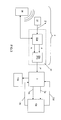
figure 3 est un exemple de synoptique des principaux composants électroniques de l'appareil de traitement de lafigure 1 , - Les
figures 4 et5 représentent des algorithmes illustrant les principales étapes de fonctionnement de l'appareil de lafigure 1 .
- The
figure 1 is a schematic representation of an exemplary medical device of the invention allowing an invasive laser treatment of a part of a human body, - The
figure 2 represents an example of a medical instrument comprising a handpiece allowing manipulation of a cannula / optical fiber assembly, - The
figure 3 is an example of a synoptic of the main electronic components of the treatment device of thefigure 1 , - The
figures 4 and5 represent algorithms illustrating the main stages of operation of the apparatus of thefigure 1 .
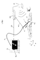
On a représenté de manière schématique sur la
Dans cet exemple particulier, mais de manière non limitative et non exhaustive de l'invention, l'appareil de traitement permet la mise en oeuvre de différents types de traitement laser invasif du corps humain. Parmi ces traitements, on peut citer de manière non exhaustive, la lipolyse laser, les traitements lasers endoveineux, le remodelage de la peau par laser, la cicatrisation de la peau par chauffage du collagène présent dans le derme et/ou par stimulation thermique au moyen d'un laser des fibroblastes pour accélérer la production de collagène dans le derme.In this particular example, but in a nonlimiting and non-exhaustive manner of the invention, the treatment apparatus allows the implementation of different types of invasive laser treatment of the human body. Among these treatments, non-exhaustive mention may be made of laser lipolysis, endovenous laser treatments, laser remodeling of the skin, scarring of the skin by heating the collagen present in the dermis and / or by thermal stimulation by means of of a fibroblast laser to accelerate the production of collagen in the dermis.
Cet appareil de traitement comporte un instrument 1, qui est manipulable à la main, et qui présente par exemple la structure particulière de la
La pièce à main 10 permet la manipulation à la main de l'ensemble canule 11/fibre optique 12, et constitue une partie non invasive de l'instrument 1. La partie de l'ensemble canule11/fibre optique 12, qui est référencée « INV » sur la
La fibre optique 12 est reliée à son autre extrémité à une source de rayonnement électromagnétique (
En référence aux
- des moyens 2 de localisation de la position absolue instantanée 3D P'(x'(t), y'(t), z'(t)) de la sortie 12a de la
fibre optique 12 dans un repère tridimensionnel prédéfini (X,Y,Z), - et des moyens électroniques 3 de contrôle de dosimétrie qui sont aptes à calculer au moins un paramètre de dosimétrie à partir au moins de ladite position absolue instantanée P'(x'(t), y'(t), z'(t)).
- means 2 for locating the instantaneous absolute position 3D P '(x' (t), y '(t), z' (t)) of the
output 12a of theoptical fiber 12 in a predefined three-dimensional reference (X, Y , Z), - and electronic dosimetry control means 3 which are capable of calculating at least one dosimetry parameter from at least said instantaneous absolute position P '(x' (t), y '(t), z' (t)) .
Un exemple particulier de réalisation des moyens de localisation 2 et des moyens électroniques de contrôle de dosimétrie 3 va à présent être détaillé.A particular embodiment of the locating means 2 and electronic dosimetry control means 3 will now be detailed.
En référence aux
Plus particulièrement, en référence à l'exemple particulier de la
En fonctionnement, l'émetteur 20 est fixe et positionné à proximité du corps C et émet un champ magnétique qui est reçu par le capteur 21. Le capteur 21 est sensible au champ magnétique produit par l'émetteur 20 et délivre des signaux électriques 21a qui sont caractéristiques de sa position absolue instantanée et de son inclinaison absolue instantanée dans ledit champ magnétique. Ces signaux électriques 21 a sont reçus et traités par des premiers moyens électroniques de calcul 22a qui sont aptes calculer en temps réel des données P[x(t), y(t), z(t)]) codant la position absolue instantanée 3D dudit capteur et des données A[α(t), β(t), θ(t)] codant l'inclinaison absolue instantanée 3D dudit capteur dans un repère tridimensionnel prédéfini (X, Y, Z).In operation, the
Le repère tridimensionnel prédéfini (X,Y, Z) est le référentiel de l'émetteur de champ magnétique 20. Lors d'un traitement, le corps C est placé dans le champ magnétique émis par cet émetteur 20, dans une position connue et la partie de corps C traitée est immobile dans le repère (X,Y,Z) pendant la durée de traitement. Le repère tridimensionnel prédéfini (X,Y,Z) est ainsi lié à la partie de corps C à traiter.The predefined three-dimensional coordinate system (X, Y, Z) is the reference frame of the
En référence à la
Les deuxièmes moyens électroniques de calcul 22b sont conçus de manière à calculer en temps réel des données P'[x'(t), y'(t), z'(t)] codant la position absolue instantanée 3D de la sortie 12a de la fibre optique 12 de l'instrument 1 dans le repère tridimensionnel (X,Y,Z), à partir desdites données codant la position absolue instantanée 3D P[X(t), Y(t), Z(t)] et l'inclinaison absolue instantanée 3D A[α(t), β(t), θ(t)] du capteur 21, et à partir de la position relative Pc(dx,dy,dz) du capteur 21.The second electronic calculation means 22b are designed so as to calculate in real time data P '[x' (t), y '(t), z' (t)] coding the instantaneous absolute position 3D of the
Dans la variante particulière de réalisation des
L'émetteur 20, le capteur 21 et les premiers moyens électroniques de calcul 22a sont des moyens connus, et peuvent par exemple, et de manière non limitative de l'invention, être constitués par les composants d'un appareil de localisation magnétique commercialisé par la société Ascension Technology Corporation sous la marque « Flock of Birds® ». Les deuxièmes moyens électroniques de calcul 22b peuvent être constitués par toute unité de traitement programmable, mettant en oeuvre par exemple microprocesseur ou microcontrôleur apte à exécuter un programme de calcul permettant de réaliser le calcul d'une position absolue instantanée 3D P'[x'(t), y'(t), z'(t)] à partir des données de position absolue instantanée 3D P[x(t), y(t), z(t)] et d'inclinaison absolue instantanée 3D A[α(t), β(t), θ(t)].The
Dans une autre variante de réalisation, les deuxièmes moyens électroniques de calcul 22b pourraient être intégrés dans le même boitier que les premiers moyens électroniques de calcul 22a. Dans une autre variante de réalisation, les premiers 22a et deuxièmes 22b moyens électroniques de calcul pourraient être réalisés en utilisant le même processeur de calcul.In another variant embodiment, the second electronic calculation means 22b could be integrated in the same housing as the first electronic calculation means 22a. In another variant embodiment, the first 22a and second 22b electronic calculation means could be implemented using the same calculation processor.
Les moyens électroniques de contrôle de dosimétrie 3 peuvent être implémentés sous la forme de tout type d'unité électronique de traitement programmable comportant notamment un microprocesseur ou microcontrôleur apte à exécuter automatiquement un programme stocké dans une mémoire et spécifique de l'invention.The electronic dosimetry control means 3 may be implemented in the form of any type of programmable electronic processing unit including in particular a microprocessor or microcontroller capable of automatically executing a program stored in a memory and specific to the invention.
Les moyens électroniques de contrôle de dosimétrie 3 reçoivent en entrée au moins des données P'[x'(t), y'(t), z'(t)] codant la position absolue instantanée 3D de la sortie 12a de la fibre optique 12, et également dans l'exemple particulier illustré deux signaux 13c et 13d délivrés par la source laser 13b. Le signal 13c permet aux moyens électroniques de contrôle de dosimétrie 3 d'être informés si un tir laser est en cours ou non. Ce signal 13c est par exemple un signal électrique de type binaire qui peut prendre deux niveaux haut et bas, et qui est par exemple à l'état haut lorsqu'un un tir est en cours (source laser activée) et à l'état bas 0 dans le cas contraire. Le signal 13c est un signal codant la puissance instantanée PUI(t) de la source laser 13b.The electronic dosimetry control means 3 receive as input at least data P '[x' (t), y '(t), z' (t)] coding the instantaneous absolute position 3D of the
Les moyens électroniques de contrôle de dosimétrie 3 sont programmés pour calculer des paramètres de dosimétrie, dont par exemple la cartographie des doses délivrées et la vitesse de déplacement de la sortie 12a de la fibre optique 12 de l'instrument 1, et pour afficher ces paramètres de dosimétrie sur l'écran 13a afin de permettre un contrôle visuel du traitement par le praticien.The electronic dosimetry control means 3 are programmed to calculate dosimetry parameters, including, for example, the mapping of the delivered doses and the speed of movement of the
Dans l'exemple particulier de réalisation de la
Les fonctionnalités des moyens 2 de localisation et des moyens électroniques de contrôle de dosimétrie 3 vont à présent être détaillées à la lumière des algorithmes de fonctionnement des
Après démarrage des moyens de localisation 2, des moyens électroniques de contrôle de dosimétrie 3 et de la source laser 13b, les moyens de localisation 2 mettent en oeuvre une première étape de calibration 401 (
Une fois les moyens de localisation 2 calibrés, les moyens de contrôle de dosimétrie 3 exécutent un programme de repérage de la zone de traitement (
Ce programme consiste à faire entrer par le praticien plusieurs points de repérage, en utilisant l'instrument 1, afin de délimiter la zone de traitement. Ce repérage est par exemple réalisé de manière non invasive, en appliquant la sortie 12a de l'instrument au contact externe du corps C, de manière à délimiter une zone de traitement en deux dimensions. Ces points de repérage sont utilisés pour l'affichage sur l'écran 13a de la zone à traiter.This program involves bringing in the practitioner several locating points, using the
Une fois ces étapes de calibration 401 et de repérage 402 terminées, l'appareil de traitement est prêt à être utilisé par le praticien.Once these 401 calibration and 402 registration steps are completed, the treatment apparatus is ready for use by the practitioner.
Le praticien réalise au moyen de l'instrument 1 le traitement laser sous-cutané ou intra-cutané approprié de manière connue en soi, selon un protocole de traitement qu'il a préalablement déterminé. Au cours de ce traitement, le praticien pratique un incision dans la peau et introduit l'extrémité de l'ensemble canule 11/fibre optique 12 sous le plan dermique derme ou dans le derme (selon le type de traitement) dans la zone de traitement qui a été repérée. Puis le praticien réalise de manière connue en soi le traitement en effectuant une série de tirs laser et en déplaçant l'ensemble canule 11/fibre optique 12 dans la zone de traitement.The practitioner uses the
Les moyens de contrôle de dosimétrie 3 sont programmés pour en cours de traitement, calculer automatiquement deux paramètres de contrôle de dosimétrie (étape 403) : la vitesse de déplacement de la sortie 12a de la fibre optique 12 , ce qui est équivalent dans cet exemple particulier d'instrument 1 à la vitesse de déplacement de la canule 11 ; la cartographie des doses d'énergie laser délivrées dans le tissu, c'est-à-dire les doses d'énergie laser délivrées en chaque point de la zone de traitement.The dosimetry control means 3 are programmed for being processed, automatically calculating two dosimetry control parameters (step 403): the displacement speed of the
La
Le calcul de la cartographie des doses d'énergie laser est effectué pour chaque tir laser et de manière itérative tant que le tir laser est effectif. Cette cartographie consiste à associer, dans un tableau 3D, à chaque position absolue instantanée 3D P'[X'(t), Y'(t), Z'(t)] de la sortie 12a de la fibre optique, la dose de rayonnement électromagnétique délivrée à cette position, c'est à dire la somme des énergies délivrée à cette position (sommation des valeurs calculée du paramètre « Delta E » de la
- les données P'[x'(t), y'(t), z'(t)] codant la position instantanée 3D de la sortie 12a de la
fibre optique 12 ; - l'information qu'un tir laser est en cours, cette information étant fournie aux moyens de contrôle de dosimétrie 3
par le signal 13c ; - la puissance du laser (paramètre « Puissance » sur la
figure 5 ), cette information étant fournie aux moyens de contrôle de dosimétrie 3par le signal 13d ; - la durée d'émission du rayonnement (paramètre « delta temps » sur la
figure 5 )
- the data P '[x' (t), y '(t), z' (t)] coding the 3D instantaneous position of the
output 12a of theoptical fiber 12; - the information that a laser firing is in progress, this information being provided to the dosimetry control means 3 by the
signal 13c; - the power of the laser (parameter "Power" on the
figure 5 ), this information being supplied to the dosimetry control means 3 by thesignal 13d; - the radiation emission duration (parameter "delta time" on the
figure 5 )
La cartographie des doses d'énergie laser délivrées dans le tissu peu également être une cartographie 2D (sommation des doses d'énergie (paramètre « Delta E » sur la
Dans une variante de réalisation plus simple, la cartographie des doses pourrait être établie en enregistrant uniquement les positions absolues successives des doses délivrées ( paramètre P'[x'(t), y'(t), z'(t)]) sans calcul d'énergie ( paramètre « Delta E »)In a simpler variant embodiment, dose mapping could be established by recording only the successive absolute positions of the doses delivered (parameter P '[x' (t), y '(t), z' (t)]) without energy calculation (parameter "Delta E")
Le calcul de la vitesse de déplacement est effectué à partir des positions instantanées 3D P'[x'(t), y'(t), z'(t)] de la sortie 12a de la fibre optique 12 qui sont successivement calculées à chaque itération.The calculation of the speed of movement is made from the 3D instantaneous positions P '[x' (t), y '(t), z' (t)] of the
Ces paramètres de dosimétrie (cartographie des doses et vitesse de déplacement de la sortie 12a de la fibre optique 12) sont en outre utilisés par les moyens de contrôle de dosimétrie 3 de la manière suivante.These dosimetry parameters (dose mapping and displacement speed of the
La vitesse de déplacement et la cartographie des doses d'énergie laser sont affichées en temps réel sur un écran 13a du dispositif 13 (
Dans une variante de réalisation, les moyens de contrôle de dosimétrie 3 peuvent avantageusement être conçus (
Dans une variante de réalisation, les moyens de contrôle de dosimétrie 3 peuvent avantageusement être conçus (
- - pour comparer automatiquement la dose délivrée par unité de surface ou par unité de volume avec au moins un seuil prédéfini, et
- - pour commander automatiquement la coupure de la
source laser 13b, au moyen du signal de commande précité 3b, en cas de détection d'un dépassement de ce seuil (détection automatique d'un surdosage).
Dans une variante de réalisation, les moyens de contrôle de dosimétrie 3 peuvent avantageusement être conçus (figure 4 ou5 / étape 406) - - pour comparer automatiquement la vitesse de déplacement de la canule 11 qui est calculée à l'étape 403 avec au moins un seuil prédéfini, et
- - pour commander automatiquement la coupure de la
source laser 13b, au moyen du signal de commande précité 3b, lorsque la vitesse de déplacement de la canule 11 qui est calculée à l'étape 403 est inférieure à ce seuil (détection automatique d'un surdosage).
- to automatically compare the dose delivered per unit of area or per unit of volume with at least one predefined threshold, and
- - To automatically control the cutoff of the
laser source 13b, by means of theaforementioned control signal 3b, in case of detection of exceeding this threshold (automatic detection of an overdose).
In an alternative embodiment, the dosimetry control means 3 may advantageously be designed (figure 4 or5 / step 406) - to automatically compare the speed of movement of the
cannula 11 which is calculated instep 403 with at least one predefined threshold, and - to automatically control the cutoff of the
laser source 13b, at 3b, when the displacement speed of thecannula 11 which is calculated instep 403 is below this threshold (automatic detection of an overdose).
Les deux modes précités de détection automatique d'un surdosage peuvent avantageusement être mis en oeuvre dans une même variante de réalisation.The two aforementioned modes of automatic detection of an overdose can advantageously be implemented in the same embodiment variant.
Grâce à ces moyens de contrôle de dosimétrie 3, le traitement peut être réalisé par le praticien avec une plus grande sécurité. En outre la cartographie de doses délivrées peut être enregistrée, et éventuellement utilisée par le praticien pour un suivi dans le temps des protocoles de traitement d'un patient.With these dosimetry control means 3, the treatment can be performed by the practitioner with greater security. In addition the mapping of delivered doses can be recorded, and possibly used by the practitioner for a follow-up in time of the treatment protocols of a patient.
L'invention n'est pas limitée à un appareil pour la mise en oeuvre d'un traitement par irradiation électromagnétique (visible, infrarouge, hyperfréquences ou radiofréquences) intra-cutanée ou sous-cutanée, mais peut également être mise en oeuvre pour contrôler les doses d'énergie délivrées au moyen d'un appareil comportant un instrument adapté pour la mise en oeuvre d'un traitement endoveineux, ou comportant un instrument de type exo-laser adapté pour la mise en oeuvre d'un traitement laser externe non invasif appliqué sur la surface de la peau.The invention is not limited to an apparatus for implementing an intra-cutaneous or subcutaneous electromagnetic irradiation treatment (visible, infra-red, microwave or radiofrequency), but can also be used to control the doses of energy delivered by means of an apparatus comprising an instrument adapted for the implementation of an endovenous treatment, or comprising an exo-laser-type instrument adapted for the implementation of an external non-invasive laser treatment applied on the surface of the skin.
La source d'énergie 13b n'est pas nécessairement une source de rayonnement électromagnétique, mais peut par exemple être une source d'énergie acoustique, l'instrument étant dans ce cas conçu pour délivrer l'énergie acoustique produite par ladite source.The
L'invention n'est pas non plus limitée à un appareil de traitement par laser, mais peut plus généralement être mise en oeuvre pour contrôler tout type de doses de traitement délivrées au moyen de tout type connu d'instrument médical, les doses pouvant par exemple être un produit chimique ou médicament administré à une partie de corps humain ou animal.The invention is also not limited to a laser treatment apparatus, but can more generally be implemented to control any type of treatment doses delivered by means of any known type of medical instrument, the doses being able to example be a chemical or drug administered to a part of a human or animal body.
L'invention peut également être mise en oeuvre pour des traitements de type invasif, tel que par exemple la liposuccion, au cours desquels on utilise un instrument invasif pour aspirer dans une partie de corps humain ou animal une quantité donnée de cellules ou tissus, tel que par exemple une canule pour aspirer les cellules graisseuses dans le cas particulier de la liposuccion. Dans ce cas, les moyens électronique de localisation permettent de localiser automatiquement la position absolue instantanée 3D (X'(t), Y'(t), Z'(t)) de l'entrée de l'instrument dans un repère tridimensionnel prédéfini, et le calcul des doses par les moyens électroniques de contrôle dosimétrie 3 correspond à la quantité de cellules ou tissus qui ont été retirés à une position de l'instrument.The invention can also be implemented for invasive type treatments, such as, for example, liposuction, during which uses an invasive instrument to suck in a part of the human or animal body a given amount of cells or tissues, such as for example a cannula for sucking the fat cells in the particular case of liposuction. In this case, the electronic location means make it possible to automatically locate the instantaneous absolute position 3D (X '(t), Y' (t), Z '(t)) of the input of the instrument in a predefined three-dimensional reference , and dosing calculation by electronic dosimetry control means 3 corresponds to the amount of cells or tissues that were removed at a position of the instrument.
L'invention peut également être appliquée à un appareil de traitement qui à la fois permet de délivrer des doses de traitement via une sortie 12a d'un instrument et permet d'aspirer des doses de traitement via une entrée d'un instrument (même instrument ou instrument différent de celui délivrant les doses). Dans ce cas, les moyens de localisation permettent de préférence de localiser dans le repère tridimensionnel (X,Y,Z) la position absolue instantanée 3D de la sortie de l'instrument délivrant les doses et la position absolue instantanée 3D de l'entrée de l'instrument aspirant les doses, et sont ainsi aptes à délivrer des données P'[(x'(t), y'(t), z'(t)] codant la position absolue instantanée 3D de la sortie de l'instrument délivrant les doses, et des données P'[(x'(t), y'(t), z'(t)] codant la position absolue instantanée 3D de l'entrée de l'instrument aspirant les doses.The invention can also be applied to a treatment apparatus which both makes it possible to deliver treatment doses via an
Claims (15)
Priority Applications (6)
| Application Number | Priority Date | Filing Date | Title |
|---|---|---|---|
| EP08370019A EP2163218A1 (en) | 2008-09-16 | 2008-09-16 | Device for treating part of a human or animal body comprising an instrument for dispensing and/or an instrument for locally sucking up treatment doses and means for controlling dosimetry |
| US12/396,990 US20100069895A1 (en) | 2008-09-16 | 2009-03-03 | Device and method for treating a part of a human or animal body implementing treatment dose delivery means and dosimetry control means |
| EP09814145A EP2341862A1 (en) | 2008-09-16 | 2009-03-04 | Apparatus and method for treating a portion of a human or animal body using a means for delivering treatment doses and a dosimetry control means |
| JP2011527365A JP2012502714A (en) | 2008-09-16 | 2009-03-04 | Apparatus and method for implementing treatment dose delivery means and dose measurement control means to treat a part of a human or animal body |
| CN2009801425909A CN102196781A (en) | 2008-09-16 | 2009-03-04 | Apparatus and method for treating a portion of a human or animal body using a means for delivering treatment doses and a dosimetry control means |
| PCT/FR2009/000228 WO2010031908A1 (en) | 2008-09-16 | 2009-03-04 | Apparatus and method for treating a portion of a human or animal body using a means for delivering treatment doses and a dosimetry control means |
Applications Claiming Priority (1)
| Application Number | Priority Date | Filing Date | Title |
|---|---|---|---|
| EP08370019A EP2163218A1 (en) | 2008-09-16 | 2008-09-16 | Device for treating part of a human or animal body comprising an instrument for dispensing and/or an instrument for locally sucking up treatment doses and means for controlling dosimetry |
Publications (1)
| Publication Number | Publication Date |
|---|---|
| EP2163218A1 true EP2163218A1 (en) | 2010-03-17 |
Family
ID=40011011
Family Applications (2)
| Application Number | Title | Priority Date | Filing Date |
|---|---|---|---|
| EP08370019A Withdrawn EP2163218A1 (en) | 2008-09-16 | 2008-09-16 | Device for treating part of a human or animal body comprising an instrument for dispensing and/or an instrument for locally sucking up treatment doses and means for controlling dosimetry |
| EP09814145A Withdrawn EP2341862A1 (en) | 2008-09-16 | 2009-03-04 | Apparatus and method for treating a portion of a human or animal body using a means for delivering treatment doses and a dosimetry control means |
Family Applications After (1)
| Application Number | Title | Priority Date | Filing Date |
|---|---|---|---|
| EP09814145A Withdrawn EP2341862A1 (en) | 2008-09-16 | 2009-03-04 | Apparatus and method for treating a portion of a human or animal body using a means for delivering treatment doses and a dosimetry control means |
Country Status (5)
| Country | Link |
|---|---|
| US (1) | US20100069895A1 (en) |
| EP (2) | EP2163218A1 (en) |
| JP (1) | JP2012502714A (en) |
| CN (1) | CN102196781A (en) |
| WO (1) | WO2010031908A1 (en) |
Cited By (1)
| Publication number | Priority date | Publication date | Assignee | Title |
|---|---|---|---|---|
| CN116617079A (en) * | 2023-07-26 | 2023-08-22 | 成都和煦医疗科技有限公司 | Moxibustion device |
Families Citing this family (9)
| Publication number | Priority date | Publication date | Assignee | Title |
|---|---|---|---|---|
| CN102626540A (en) * | 2011-02-22 | 2012-08-08 | 深圳市倍轻松科技股份有限公司 | Photon therapy control system and chair for photon therapy |
| JP5665994B2 (en) * | 2011-08-17 | 2015-02-04 | 三菱電機株式会社 | Skin dose evaluation support device and treatment planning device |
| US9901398B2 (en) | 2012-06-29 | 2018-02-27 | Covidien Lp | Microwave antenna probes |
| FR3073387A1 (en) * | 2017-11-13 | 2019-05-17 | Lso Medical | ENDOVENOUS TREATMENT ASSEMBLY AND DEVICE |
| US11129679B2 (en) | 2017-11-14 | 2021-09-28 | Mako Surgical Corp. | Fiber optic tracking system |
| US11129518B2 (en) * | 2018-05-05 | 2021-09-28 | Ankon Medical Technologies (Shanghai) Co., Ltd. | Portable system and method for position and orientation of remote objects |
| EP4166192A1 (en) * | 2021-10-14 | 2023-04-19 | Koninklijke Philips N.V. | An apparatus for user guidance during skin treatment and method thereof |
| US11931102B2 (en) * | 2022-05-17 | 2024-03-19 | BellaMia Technologies, Inc. | Laser treatment safety system |
| WO2023225411A1 (en) * | 2022-05-17 | 2023-11-23 | BellaMia Technologies, Inc. | Systems and methods for laser skin treatment |
Citations (14)
| Publication number | Priority date | Publication date | Assignee | Title |
|---|---|---|---|---|
| US4564011A (en) | 1982-03-22 | 1986-01-14 | Leon Goldman | Laser optic device and method |
| US5531739A (en) | 1994-09-23 | 1996-07-02 | Coherent, Inc. | Method of treating veins |
| US5954710A (en) | 1996-02-13 | 1999-09-21 | El.En. S.P.A. | Device and method for eliminating adipose layers by means of laser energy |
| WO2000048644A2 (en) * | 1999-02-17 | 2000-08-24 | Vidaderm | Systems and methods for shrinking collagen in the dermis |
| US6206873B1 (en) | 1996-02-13 | 2001-03-27 | El. En. S.P.A. | Device and method for eliminating adipose layers by means of laser energy |
| US6398777B1 (en) | 1999-02-01 | 2002-06-04 | Luis Navarro | Endovascular laser device and treatment of varicose veins |
| US20030040739A1 (en) | 2001-08-21 | 2003-02-27 | Koop Dale E. | Enhanced noninvasive collagen remodeling |
| US6659999B1 (en) | 1997-02-05 | 2003-12-09 | Candela Corporation | Method and apparatus for treating wrinkles in skin using radiation |
| US20040199151A1 (en) | 2003-04-03 | 2004-10-07 | Ceramoptec Industries, Inc. | Power regulated medical underskin irradiation treament system |
| US20050154380A1 (en) | 2003-12-23 | 2005-07-14 | Debenedictis Leonard C. | Method and apparatus for monitoring and controlling laser-induced tissue treatment |
| US20060224148A1 (en) | 2005-04-05 | 2006-10-05 | Cho George E | System and method for laser lipolysis |
| WO2007027962A2 (en) * | 2005-08-29 | 2007-03-08 | Reliant Technologies, Inc. | Method and apparatus for monitoring and controlling thermally induced tissue treatment |
| WO2008067455A2 (en) * | 2006-11-30 | 2008-06-05 | Stryker Corporation | System and method for targeted activation of a pharmaceutical agent within the body cavity that is activated by the application of energy |
| US20080215041A1 (en) * | 2007-03-02 | 2008-09-04 | Optical System & Research For Industry And Science Osyris Sa | Cannula/optical fibre assembly and laser instrument including said assembly |
Family Cites Families (33)
| Publication number | Priority date | Publication date | Assignee | Title |
|---|---|---|---|---|
| US5385544A (en) * | 1992-08-12 | 1995-01-31 | Vidamed, Inc. | BPH ablation method and apparatus |
| US4967745A (en) * | 1987-04-10 | 1990-11-06 | Massachusetts Institute Of Technology | Multi-fiber plug for a laser catheter |
| DE3650688T2 (en) * | 1985-03-22 | 1999-03-25 | Massachusetts Inst Technology | Fiber optic probe system for the spectral diagnosis of tissue |
| US4896673A (en) * | 1988-07-15 | 1990-01-30 | Medstone International, Inc. | Method and apparatus for stone localization using ultrasound imaging |
| US5230623A (en) * | 1991-12-10 | 1993-07-27 | Radionics, Inc. | Operating pointer with interactive computergraphics |
| US5391199A (en) * | 1993-07-20 | 1995-02-21 | Biosense, Inc. | Apparatus and method for treating cardiac arrhythmias |
| US6241725B1 (en) * | 1993-12-15 | 2001-06-05 | Sherwood Services Ag | High frequency thermal ablation of cancerous tumors and functional targets with image data assistance |
| US6019724A (en) * | 1995-02-22 | 2000-02-01 | Gronningsaeter; Aage | Method for ultrasound guidance during clinical procedures |
| US6575969B1 (en) * | 1995-05-04 | 2003-06-10 | Sherwood Services Ag | Cool-tip radiofrequency thermosurgery electrode system for tumor ablation |
| US6256529B1 (en) * | 1995-07-26 | 2001-07-03 | Burdette Medical Systems, Inc. | Virtual reality 3D visualization for surgical procedures |
| US5638819A (en) * | 1995-08-29 | 1997-06-17 | Manwaring; Kim H. | Method and apparatus for guiding an instrument to a target |
| DE69731322T2 (en) * | 1996-06-11 | 2005-03-17 | Roke Manor Research Ltd., Romsey | A catheter tracking system |
| WO2000053261A1 (en) * | 1999-03-08 | 2000-09-14 | Asah Medico A/S | An apparatus for tissue treatment and having a monitor for display of tissue features |
| GB2331807B (en) * | 1997-11-15 | 2002-05-29 | Roke Manor Research | Catheter tracking system |
| US6021343A (en) * | 1997-11-20 | 2000-02-01 | Surgical Navigation Technologies | Image guided awl/tap/screwdriver |
| ES2255155T3 (en) * | 1998-02-05 | 2006-06-16 | Biosense Webster, Inc. | DEVICE FOR THE INTRACARDIAC ADMINISTRATION OF PHARMACOS. |
| WO2000016684A1 (en) * | 1998-09-24 | 2000-03-30 | Super Dimension Ltd. | System and method for determining the location of a catheter during an intra-body medical procedure |
| US6478793B1 (en) * | 1999-06-11 | 2002-11-12 | Sherwood Services Ag | Ablation treatment of bone metastases |
| US8540704B2 (en) * | 1999-07-14 | 2013-09-24 | Cardiofocus, Inc. | Guided cardiac ablation catheters |
| US6892091B1 (en) * | 2000-02-18 | 2005-05-10 | Biosense, Inc. | Catheter, method and apparatus for generating an electrical map of a chamber of the heart |
| AU2001247440A1 (en) * | 2000-03-15 | 2001-09-24 | Cardiac Focus, Inc. | Non-invasive localization and treatment of focal atrial fibrillation |
| US6484118B1 (en) * | 2000-07-20 | 2002-11-19 | Biosense, Inc. | Electromagnetic position single axis system |
| US6464662B1 (en) * | 2000-07-26 | 2002-10-15 | Image-Guided Neurologics, Inc. | Drug delivery and catheter systems, apparatus and processes |
| EP1485019A4 (en) * | 2000-09-07 | 2009-03-04 | Zeiss Carl Ag | Method and apparatus for image-guided radiotherapy |
| DE10051244A1 (en) * | 2000-10-17 | 2002-05-16 | Philips Corp Intellectual Pty | X-ray free intravascular localization and imaging procedure |
| US20030045798A1 (en) * | 2001-09-04 | 2003-03-06 | Richard Hular | Multisensor probe for tissue identification |
| US7001383B2 (en) * | 2002-10-21 | 2006-02-21 | Biosense, Inc. | Real-time monitoring and mapping of ablation lesion formation in the heart |
| US7306593B2 (en) * | 2002-10-21 | 2007-12-11 | Biosense, Inc. | Prediction and assessment of ablation of cardiac tissue |
| WO2005065371A2 (en) * | 2003-12-30 | 2005-07-21 | Liposonix, Inc. | Systems and methods for the destruction of adipose tissue |
| JP4847442B2 (en) * | 2004-04-02 | 2011-12-28 | コーニンクレッカ フィリップス エレクトロニクス エヌ ヴィ | Ultrasonic intracavity probe for 3D imaging |
| US7367944B2 (en) * | 2004-12-13 | 2008-05-06 | Tel Hashomer Medical Research Infrastructure And Services Ltd. | Method and system for monitoring ablation of tissues |
| US8190238B2 (en) * | 2005-12-09 | 2012-05-29 | Hansen Medical, Inc. | Robotic catheter system and methods |
| GB2441306A (en) * | 2006-09-01 | 2008-03-05 | Microsulis Ltd | Endometrial treatment device with stepper actuator, angular sweep rate sensor and bending deflection sensor |
-
2008
- 2008-09-16 EP EP08370019A patent/EP2163218A1/en not_active Withdrawn
-
2009
- 2009-03-03 US US12/396,990 patent/US20100069895A1/en not_active Abandoned
- 2009-03-04 EP EP09814145A patent/EP2341862A1/en not_active Withdrawn
- 2009-03-04 JP JP2011527365A patent/JP2012502714A/en active Pending
- 2009-03-04 WO PCT/FR2009/000228 patent/WO2010031908A1/en active Application Filing
- 2009-03-04 CN CN2009801425909A patent/CN102196781A/en active Pending
Patent Citations (16)
| Publication number | Priority date | Publication date | Assignee | Title |
|---|---|---|---|---|
| US4564011A (en) | 1982-03-22 | 1986-01-14 | Leon Goldman | Laser optic device and method |
| US5531739A (en) | 1994-09-23 | 1996-07-02 | Coherent, Inc. | Method of treating veins |
| US5954710A (en) | 1996-02-13 | 1999-09-21 | El.En. S.P.A. | Device and method for eliminating adipose layers by means of laser energy |
| US6206873B1 (en) | 1996-02-13 | 2001-03-27 | El. En. S.P.A. | Device and method for eliminating adipose layers by means of laser energy |
| US6659999B1 (en) | 1997-02-05 | 2003-12-09 | Candela Corporation | Method and apparatus for treating wrinkles in skin using radiation |
| US6398777B1 (en) | 1999-02-01 | 2002-06-04 | Luis Navarro | Endovascular laser device and treatment of varicose veins |
| WO2000048644A2 (en) * | 1999-02-17 | 2000-08-24 | Vidaderm | Systems and methods for shrinking collagen in the dermis |
| US20030040739A1 (en) | 2001-08-21 | 2003-02-27 | Koop Dale E. | Enhanced noninvasive collagen remodeling |
| US20040199151A1 (en) | 2003-04-03 | 2004-10-07 | Ceramoptec Industries, Inc. | Power regulated medical underskin irradiation treament system |
| US20050154380A1 (en) | 2003-12-23 | 2005-07-14 | Debenedictis Leonard C. | Method and apparatus for monitoring and controlling laser-induced tissue treatment |
| WO2005063138A1 (en) * | 2003-12-23 | 2005-07-14 | Reliant Technologies, Inc. | Method and apparatus for monitoring and controlling laser-induced tissue treatment |
| US20060224148A1 (en) | 2005-04-05 | 2006-10-05 | Cho George E | System and method for laser lipolysis |
| WO2006107522A2 (en) | 2005-04-05 | 2006-10-12 | El. En. S.P.A. | System and method for laser lipolysis |
| WO2007027962A2 (en) * | 2005-08-29 | 2007-03-08 | Reliant Technologies, Inc. | Method and apparatus for monitoring and controlling thermally induced tissue treatment |
| WO2008067455A2 (en) * | 2006-11-30 | 2008-06-05 | Stryker Corporation | System and method for targeted activation of a pharmaceutical agent within the body cavity that is activated by the application of energy |
| US20080215041A1 (en) * | 2007-03-02 | 2008-09-04 | Optical System & Research For Industry And Science Osyris Sa | Cannula/optical fibre assembly and laser instrument including said assembly |
Cited By (2)
| Publication number | Priority date | Publication date | Assignee | Title |
|---|---|---|---|---|
| CN116617079A (en) * | 2023-07-26 | 2023-08-22 | 成都和煦医疗科技有限公司 | Moxibustion device |
| CN116617079B (en) * | 2023-07-26 | 2023-09-22 | 成都和煦医疗科技有限公司 | Moxibustion device |
Also Published As
| Publication number | Publication date |
|---|---|
| CN102196781A (en) | 2011-09-21 |
| JP2012502714A (en) | 2012-02-02 |
| WO2010031908A1 (en) | 2010-03-25 |
| US20100069895A1 (en) | 2010-03-18 |
| EP2341862A1 (en) | 2011-07-13 |
Similar Documents
| Publication | Publication Date | Title |
|---|---|---|
| EP2163218A1 (en) | Device for treating part of a human or animal body comprising an instrument for dispensing and/or an instrument for locally sucking up treatment doses and means for controlling dosimetry | |
| JP6357201B2 (en) | Devices and methods for radiation-based dermatological treatment | |
| US7309335B2 (en) | Dermatological treatment with visualization | |
| US6406474B1 (en) | Device and method for application of radiation | |
| US8244369B2 (en) | Device and method for treating skin with temperature control | |
| US7740651B2 (en) | Vacuum assisted treatment of the skin | |
| US20080154247A1 (en) | Apparatus and method for hair removal and follicle devitalization | |
| US20060095096A1 (en) | Interchangeable tips for medical laser treatments and methods for using same | |
| US8702772B2 (en) | Device for dermatological use with a failsafe control | |
| CN112584788A (en) | Hand-held device for performing a treatment operation on skin | |
| KR20080006574A (en) | System and method for laser lipolysis | |
| US20080154251A1 (en) | Interchangeable Tips for Medical Laser Treatments and Methods for Using Same | |
| US20200397312A1 (en) | System and methods for lesion characterization in blood vessels | |
| EP2025299A1 (en) | Method and system for controlling a treatment by sub-cutaneous or intra-cutaneous irradiation using electromagnetic radiation | |
| EP2124793B1 (en) | Equipment for treating wounds | |
| EP2340087B1 (en) | Device for therapeutic treatment | |
| US10456198B2 (en) | Guided wave ablation and sensing | |
| CN106714667B (en) | Light-based collagen measurement system and skin treatment system | |
| CA3065092A1 (en) | Positioning device for positioning a light-conducting fibre in a calibration port | |
| US20080188847A1 (en) | Biofeedback | |
| US20240009478A1 (en) | Dermal light delivery device for light therapy | |
| FR2938179A1 (en) | Skin cicatrization assisting device for patient, has laser sources emitting beam whose wavelength is in specific range, and microcontrollers controlling laser sources according to data relative to type of skin of patient to be treated | |
| FR2766721A1 (en) | INTRACORPOREAL PROBE COMPRISING AN INTERSTITIAL TEMPERATURE MEASURING DEVICE AND THERAPEUTIC TREATMENT APPARATUS INCLUDING APPLICATION |
Legal Events
| Date | Code | Title | Description |
|---|---|---|---|
| PUAI | Public reference made under article 153(3) epc to a published international application that has entered the european phase |
Free format text: ORIGINAL CODE: 0009012 |
|
| AK | Designated contracting states |
Kind code of ref document: A1 Designated state(s): AT BE BG CH CY CZ DE DK EE ES FI FR GB GR HR HU IE IS IT LI LT LU LV MC MT NL NO PL PT RO SE SI SK TR |
|
| AX | Request for extension of the european patent |
Extension state: AL BA MK RS |
|
| AKY | No designation fees paid | ||
| REG | Reference to a national code |
Ref country code: DE Ref legal event code: 8566 |
|
| STAA | Information on the status of an ep patent application or granted ep patent |
Free format text: STATUS: THE APPLICATION IS DEEMED TO BE WITHDRAWN |
|
| 18D | Application deemed to be withdrawn |
Effective date: 20100918 |