EP1742319A2 - Automatisches Schliesssystem mit Fernsteuerung der Kraft - Google Patents
Automatisches Schliesssystem mit Fernsteuerung der Kraft Download PDFInfo
- Publication number
- EP1742319A2 EP1742319A2 EP20060013193 EP06013193A EP1742319A2 EP 1742319 A2 EP1742319 A2 EP 1742319A2 EP 20060013193 EP20060013193 EP 20060013193 EP 06013193 A EP06013193 A EP 06013193A EP 1742319 A2 EP1742319 A2 EP 1742319A2
- Authority
- EP
- European Patent Office
- Prior art keywords
- mobile structure
- limiting
- motor
- force
- closing system
- Prior art date
- Legal status (The legal status is an assumption and is not a legal conclusion. Google has not performed a legal analysis and makes no representation as to the accuracy of the status listed.)
- Withdrawn
Links
Images
Classifications
-
- H—ELECTRICITY
- H02—GENERATION; CONVERSION OR DISTRIBUTION OF ELECTRIC POWER
- H02H—EMERGENCY PROTECTIVE CIRCUIT ARRANGEMENTS
- H02H7/00—Emergency protective circuit arrangements specially adapted for specific types of electric machines or apparatus or for sectionalised protection of cable or line systems, and effecting automatic switching in the event of an undesired change from normal working conditions
- H02H7/08—Emergency protective circuit arrangements specially adapted for specific types of electric machines or apparatus or for sectionalised protection of cable or line systems, and effecting automatic switching in the event of an undesired change from normal working conditions for dynamo-electric motors
- H02H7/085—Emergency protective circuit arrangements specially adapted for specific types of electric machines or apparatus or for sectionalised protection of cable or line systems, and effecting automatic switching in the event of an undesired change from normal working conditions for dynamo-electric motors against excessive load
- H02H7/0851—Emergency protective circuit arrangements specially adapted for specific types of electric machines or apparatus or for sectionalised protection of cable or line systems, and effecting automatic switching in the event of an undesired change from normal working conditions for dynamo-electric motors against excessive load for motors actuating a movable member between two end positions, e.g. detecting an end position or obstruction by overload signal
-
- H—ELECTRICITY
- H02—GENERATION; CONVERSION OR DISTRIBUTION OF ELECTRIC POWER
- H02H—EMERGENCY PROTECTIVE CIRCUIT ARRANGEMENTS
- H02H3/00—Emergency protective circuit arrangements for automatic disconnection directly responsive to an undesired change from normal electric working condition with or without subsequent reconnection ; integrated protection
- H02H3/006—Calibration or setting of parameters
-
- H—ELECTRICITY
- H02—GENERATION; CONVERSION OR DISTRIBUTION OF ELECTRIC POWER
- H02H—EMERGENCY PROTECTIVE CIRCUIT ARRANGEMENTS
- H02H7/00—Emergency protective circuit arrangements specially adapted for specific types of electric machines or apparatus or for sectionalised protection of cable or line systems, and effecting automatic switching in the event of an undesired change from normal working conditions
- H02H7/08—Emergency protective circuit arrangements specially adapted for specific types of electric machines or apparatus or for sectionalised protection of cable or line systems, and effecting automatic switching in the event of an undesired change from normal working conditions for dynamo-electric motors
- H02H7/085—Emergency protective circuit arrangements specially adapted for specific types of electric machines or apparatus or for sectionalised protection of cable or line systems, and effecting automatic switching in the event of an undesired change from normal working conditions for dynamo-electric motors against excessive load
- H02H7/0856—Emergency protective circuit arrangements specially adapted for specific types of electric machines or apparatus or for sectionalised protection of cable or line systems, and effecting automatic switching in the event of an undesired change from normal working conditions for dynamo-electric motors against excessive load characterised by the protection measure taken
- H02H7/0857—Emergency protective circuit arrangements specially adapted for specific types of electric machines or apparatus or for sectionalised protection of cable or line systems, and effecting automatic switching in the event of an undesired change from normal working conditions for dynamo-electric motors against excessive load characterised by the protection measure taken by lowering the mechanical load of the motor
Definitions
- the present invention relates to an automated closing system with remote control of the force, usable for passages or openings closed by mobile structures, as gates, doors, main doors, etc.
- the term “mobile structure” will be used for defining any mobile structure which can be used for closing a passage and which can be constituted by a gate, a door, a main door, etc, provided with one or more leaves, of swinging or sliding type.
- the term “closing system” defines the whole of the means suitable to move the mobile structure, that is the motor means with the relevant command and control means used for the operations of opening and closing the passage.
- the force of the wing of a gate is limited by means of the control of preset values.
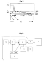
- Fig.1 a diagram relevant to the curve of one of the aforesaid values; in particular, it is shown -in relationship with the time- the force exercised on an obstacle at the moment of the impact, according to the regulation relevant to the safety of the automated closings (Cir. Machines 98/37/CE and, in the specific, norm EN12453).
- the diagram represents a function which correlates values of the time (axis of the abscissas) with values of the found force (other axis).
- the four parameters which must be controlled are:
- the limiting device is a power limiting device acting on the driven shaft.
- the motor means acts on a oleo-dynamic cylinder, the limiting device will act on the values of pressure.
- the devices for limiting the force are indispensable in order to guarantee the safety of the system in the normal operating conditions, but they have drawbacks relevant to some limit or emergency situations.
- the limiting devices prevent or interrupt the motion of the mobile structure owing to obstacles which determine the increase of the demand of force for the motion.
- the mobile structure has a greater resistance in its motion; this increase of the resistance determines the activation of the limiting devices which prevent the opening and/or the motion of the mobile structure and, consequently, it is not possible to obtain the opening.
- the limiting devices prevent such operation.
- the main aim of the present invention is to provide an automated closing system which can eliminate the above mentioned drawbacks.
- a present invention there is that it is possible to obtain the motion of the mobile structure, that is the opening of the passage, without difficult operations, which require a specific technical background or suitable tools; that the motion of the mobile structure is allowed only temporarily, with the restoration of the original conditions after the motion intervention; that the system allows to regulate the action of means for deactivating, so that the inhibition of means of limitation can be partial or total; that the system can be used on mobile structures of various type; that the idea of solution of the present invention can be applied to automated systems already existing; that the system maintains its characteristics unchanged also after long periods of use, requiring a extremely reduced maintenance.
- An automated system of closing (1) in compliance with the present invention is usable for passages or openings closed by a mobile structure (4).
- the system (1) comprises motor means (2) acting on the mobile structure (4) and means for limiting (5) said motor means (2), suitable to deactivate or modify the motion of the motor means (2) in correspondence of the overcoming of a preset threshold value.
- the system (1) comprises means (7) for temporarily deactivating said means (5) for limiting the motor means (2), in order to allow, receiving a command, the movement of said mobile structure (4) also in conditions of overcoming of said threshold value.
- the motor means (2) are connected to the mobile structure (4) by relevant transmission means (3).
- the means of transmission of the motion (3) can be formed, for a sliding gate, by the driven shaft of the motor, by one or more gears, by a rack rail, etc.
- the limiting device (5) will be able to act on the electric motor measuring, as an example, the electrical current absorption necessary to the motion of the mobile structure (4) in order to operate in case the force exceeds a preset value of threshold.
- the limiting device (5) will use a value relating to the pressure in order to estimate the overcoming of the threshold value.
- the threshold value is settable and can be changed through a relative regulation device, represented by the block (50) in Fig.2.
- the system (1) is provide with means (7) for temporarily deactivating the limiting device (5).
- the means for limiting (5) is "bypassed" with a simple command, also remote controlled, so as to obtain the motion of the mobile structure (4) also in conditions in which, normally, the motion is not allowed, that is over the threshold value.
- the system allows to regulate the action of deactivating means (7), so that the inhibition of limiting means (5) can be partial or total.
- the block (6) indicates a remote control usable for the normal opening of the passage.
- (60) is indicated the push-button which is normally pushed for the opening. Pushing such push-button (60) is obtained (2) the activation of motor means if the limiting device (5) is not acting. In situations of overcoming of the threshold value, the intervention of the limiting means (5) prevents the motion, or determines the arrest or the reversal of the motion of motor means.
- using the other push-button (61) a signal is sent to the means (7) for temporarily deactivating the limiting means (5).
- the information sent through the push-button (61) can be codified in various way, so as to concur the partial or total deactivation of the limiting means (5).
- said deactivating means can be enclosed in a micro-controller or, more in general terms, in the electronic circuits that regulate the distribution of power to motor means (2).
- the deactivation of limiting means (5) consists in supplying all the current that the feeding means can supply, bypassing the current dividing circuits normally used in order to respect the limits of force established by the norms.
- limiting means (5) In alternative, if the deactivation of limiting means (5) must be only partial, a current value greater than the value normally used will be supplied, but the action of limiting means (5) will be allowed with an elevated threshold.
- the command signal for the deactivating means (7) can be sent non only by the remote control (6), but also using a lock push-button (70) opportunely connected to the means (7), in order to allow the deactivation with the relevant key, also without a remote control. Also in this case, the deactivation of the limiting means (5) will be temporary, so as to re-establish the original conditions after the emergency opening of the mobile structure (2).
Landscapes
- Power-Operated Mechanisms For Wings (AREA)
Applications Claiming Priority (1)
| Application Number | Priority Date | Filing Date | Title |
|---|---|---|---|
| ITBO20050452 ITBO20050452A1 (it) | 2005-07-05 | 2005-07-05 | Sistema automatizzato di chiusura |
Publications (1)
| Publication Number | Publication Date |
|---|---|
| EP1742319A2 true EP1742319A2 (de) | 2007-01-10 |
Family
ID=37055076
Family Applications (1)
| Application Number | Title | Priority Date | Filing Date |
|---|---|---|---|
| EP20060013193 Withdrawn EP1742319A2 (de) | 2005-07-05 | 2006-06-27 | Automatisches Schliesssystem mit Fernsteuerung der Kraft |
Country Status (2)
| Country | Link |
|---|---|
| EP (1) | EP1742319A2 (de) |
| IT (1) | ITBO20050452A1 (de) |
-
2005
- 2005-07-05 IT ITBO20050452 patent/ITBO20050452A1/it unknown
-
2006
- 2006-06-27 EP EP20060013193 patent/EP1742319A2/de not_active Withdrawn
Also Published As
| Publication number | Publication date |
|---|---|
| ITBO20050452A1 (it) | 2007-01-06 |
Similar Documents
| Publication | Publication Date | Title |
|---|---|---|
| DE4214998C2 (de) | Torantrieb und Verfahren zum Betreiben eines Torantriebes | |
| US10871020B2 (en) | Method for operating a building closure | |
| US7960932B2 (en) | Method for controlling an electrical door drive | |
| EP1340877A2 (de) | Türantrieb | |
| WO1998040945A1 (de) | Verfahren zur elektrischen steuerung und regelung der bewegung von elektrisch betriebenen aggregaten | |
| DE202004000266U1 (de) | Steuerungsvorrichtung einer Verstelleinrichtung eines Kraftfahrzeugs, insbesondere eines Kraftfahrzeugfensterhebers | |
| DE60020078T2 (de) | Verbesserungen an Klemmschutzvorrichtungen für Automobile | |
| WO2003087510A3 (en) | A balance control system for a movable barrier operator | |
| US20090031631A1 (en) | Automated closing system with remote control of the force | |
| EP2188476B1 (de) | Linearantrieb für schiebetüren oder dergleichen | |
| CN110582457B (zh) | 利用安全触板的电梯的防夹手用安全装置 | |
| EP1742319A2 (de) | Automatisches Schliesssystem mit Fernsteuerung der Kraft | |
| EP3361029A1 (de) | Antriebseinrichtung für einen tür- oder fensterflügel | |
| KR101242147B1 (ko) | 철도차량 출입문 제어장치 | |
| DE19537304C2 (de) | Antriebssystem für Verschließelemente | |
| EP1438778B1 (de) | Verfahren zur überwachung des reversiervorgangs von elektrisch betätigbaren aggregaten | |
| DE102009008132B4 (de) | Torsteuerung zur Steuerung eines elektromotorisch angetriebenen Tores | |
| KR101844200B1 (ko) | 엘리베이터 도어 개폐 장치 및 엘리베이터 도어 개폐 장치의 개수 방법 | |
| EP3361034B1 (de) | Feststell- und/oder notöffnungsanlage | |
| JP2025505506A (ja) | 解錠システム、施錠/解錠ユニット、解錠システムの操作方法 | |
| DE102021208896A1 (de) | Verfahren zur elektronischen Überwachung und Steuerung des Öffnungs- und Schließvorganges von elektrisch betriebenen Aggregaten, insbesondere von Fensterhebern und Schiebedächern in Kraftfahrzeugen | |
| EP3361027B1 (de) | Feststelleinrichtung | |
| DE10019123B4 (de) | Einrichtung zur Drehmomentbegrenzung und Überlastabschaltung von Antrieben mit einem Einphasenkurzschlußläufermotor, insbesondere für Rauch- und Wärmeabzüge | |
| ATE399386T1 (de) | Steuerungs-verfahren und vorrichtung für die mechanische sicherheit eines tores oder einer tür mit wenigstens einem elektrisch betriebenen flügel | |
| GB2415739B (en) | Releasable door jamb assembly |
Legal Events
| Date | Code | Title | Description |
|---|---|---|---|
| PUAI | Public reference made under article 153(3) epc to a published international application that has entered the european phase |
Free format text: ORIGINAL CODE: 0009012 |
|
| AK | Designated contracting states |
Kind code of ref document: A2 Designated state(s): AT BE BG CH CY CZ DE DK EE ES FI FR GB GR HU IE IS IT LI LT LU LV MC NL PL PT RO SE SI SK TR |
|
| AX | Request for extension of the european patent |
Extension state: AL BA HR MK YU |
|
| STAA | Information on the status of an ep patent application or granted ep patent |
Free format text: STATUS: THE APPLICATION IS DEEMED TO BE WITHDRAWN |
|
| 18D | Application deemed to be withdrawn |
Effective date: 20130103 |