EP1742128A1 - Servo controller - Google Patents
Servo controller Download PDFInfo
- Publication number
- EP1742128A1 EP1742128A1 EP06014043A EP06014043A EP1742128A1 EP 1742128 A1 EP1742128 A1 EP 1742128A1 EP 06014043 A EP06014043 A EP 06014043A EP 06014043 A EP06014043 A EP 06014043A EP 1742128 A1 EP1742128 A1 EP 1742128A1
- Authority
- EP
- European Patent Office
- Prior art keywords
- servo controller
- side drive
- drive source
- correction data
- positional deviation
- Prior art date
- Legal status (The legal status is an assumption and is not a legal conclusion. Google has not performed a legal analysis and makes no representation as to the accuracy of the status listed.)
- Granted
Links
Images




Classifications
-
- G—PHYSICS
- G05—CONTROLLING; REGULATING
- G05B—CONTROL OR REGULATING SYSTEMS IN GENERAL; FUNCTIONAL ELEMENTS OF SUCH SYSTEMS; MONITORING OR TESTING ARRANGEMENTS FOR SUCH SYSTEMS OR ELEMENTS
- G05B19/00—Program-control systems
- G05B19/02—Program-control systems electric
- G05B19/18—Numerical control [NC], i.e. automatically operating machines, in particular machine tools, e.g. in a manufacturing environment, so as to execute positioning, movement or co-ordinated operations by means of program data in numerical form
- G05B19/19—Numerical control [NC], i.e. automatically operating machines, in particular machine tools, e.g. in a manufacturing environment, so as to execute positioning, movement or co-ordinated operations by means of program data in numerical form characterised by positioning or contouring control systems, e.g. to control position from one programmed point to another or to control movement along a programmed continuous path
- G05B19/195—Controlling the position of several slides on one axis
-
- G—PHYSICS
- G05—CONTROLLING; REGULATING
- G05B—CONTROL OR REGULATING SYSTEMS IN GENERAL; FUNCTIONAL ELEMENTS OF SUCH SYSTEMS; MONITORING OR TESTING ARRANGEMENTS FOR SUCH SYSTEMS OR ELEMENTS
- G05B19/00—Program-control systems
- G05B19/02—Program-control systems electric
- G05B19/18—Numerical control [NC], i.e. automatically operating machines, in particular machine tools, e.g. in a manufacturing environment, so as to execute positioning, movement or co-ordinated operations by means of program data in numerical form
- G05B19/414—Structure of the control system, e.g. common controller or multiprocessor systems, interface to servo, programmable interface controller
- G05B19/4141—Structure of the control system, e.g. common controller or multiprocessor systems, interface to servo, programmable interface controller characterised by a controller or microprocessor per axis
Definitions
- the present invention relates to a servo controller for synchronously controlling a master side drive source and a slave side drive source when the servo controller is applied to a machine in which the same machining is repeatedly conducted and, for example, thread cutting or tapping is repeatedly conducted.
- a predetermined depth of cut is given to a thread cutting tool and the thread cutting tool is linearly moved in the axial direction of the work so as to conduct thread cutting on the work.
- the depth of cut is given to the cutting tool being divided by several times, that is, cutting of a predetermined depth is repeated by a predetermined number of times so that a perfect thread shape can be formed.
- a feed speed of the cutting tool in the case of machining a male screw and a feed speed of the tap in the case of machining a female screw are determined according to the rotary speeds of the work and tap so that the screw can be continuously formed at a predetermined pitch. That is, a movement command (feed speed) of the cutting tool or the tap, which is linearly moved, and a rotation command (rotary speed) of the rotating work or the rotating tap are maintained at a predetermined ratio. Therefore, in this type of thread cutting or tapping, in order for both drive sources (servo motors) to be synchronously driven at a predetermined ratio, the rotation command and the movement command are given by a numerical controller of a machine tool.
- a position detecting unit of a feed axis driven by one drive source is 10000 pulse/mm and a position detecting unit of a rotary axis driven by the other drive source is 4096 pulse/rev.
- the rotary axis is rotated one revolution in 10 ms and the feed axis advances 1 mm per revolution. Therefore, the number of pulses becomes 10000 pulse/10 ms.
- a feed speed of the feed axis becomes 6 m/min.
- the number of pulses of the rotary axis becomes 4096/10 ms.
- a pair of driving axes are a rotary axis and a feed axis.
- both of the pair of driving axes may be respectively a feed axis.
- both of the pair of driving axes may be respectively a rotary axis. That is, the present invention is not limited to the above specific embodiment of the drive axis.
- JP-A-2004-280772 discloses an example of the conventional servo controller in which the respective drive sources of the rotary and the feed axis are synchronously controlled so that a work can be repeatedly machined into the same shape.
- the synchronization error is increased by a cutting disturbance such as a change in the depth of cut of a cutting tool or a shock caused at the time of starting cutting. Furthermore, the synchronization error is increased by the friction. Being affected by the cutting disturbance and friction, the accuracy of machining a screw is deteriorated.
- the speed of the feed axis is 6 m/min -1
- the rotation - linearity conversion coefficient for example, the pitch of a ball screw
- the rotary speed of the feed axis is 600 min -1 , which is 1/10 of the rotary speed of the rotary axis. In this way, even when the axes are driven by the same synchronization command, the speed of the rotary axis must be higher than that of the feed axis by 10 times.
- An object of the present invention is to provide a servo controller capable of highly accurately and efficiently conducting machining by reducing a synchronization error between a rotary axis side and a feed shaft side even when the inertia of the rotary axis is high or even when the rotary axis is rotated at a high speed.
- the present invention provides a servo controller by which a master side drive source for driving one drive axis and a slave side drive source for driving the other drive axis are synchronously controlled, and the servo controller includes a correction data calculating means for calculating correction data to correct positional deviation of the slave side drive source according to the synchronous error, which is a difference between the positional deviation of the master side drive source and the positional deviation of the slave side drive source, wherein the correction data is added to the positional deviation of the slave side drive source.
- the correction data calculating means calculates correction data to correct the positional deviation of the slave side drive source according to the synchronization error, and when this correction error is added to the positional deviation of the slave side drive source, it is possible to conduct control so that the synchronization error can come close to zero. Therefore, an amount of the positional deviation of the slave side motor can be adjusted according to an amount of positional deviation of the master side drive source. That is, in the case where the amount of the positional deviation of the master side drive source is large, correction is conducted so that the amount of the positional deviation of the slave side drive source can be increased.
- the present invention provides a servo controller by which a master side drive source for driving one drive axis and a slave side drive source for driving the other drive axis are synchronously controlled, and the servo controller includes: a selection means capable of selecting one of the synchronization error, which is a difference between the positional deviation of the master side drive source and the positional deviation of the slave side drive source, and the positional deviation of the slave side drive source; and a correction data calculating means for calculating correction data to correct positional deviation of the slave side drive source according to one data selected by the selecting means, wherein the correction data is added to the positional deviation of the slave side drive axis and control is conducted so that the positional deviation or the synchronous error can come close to zero.
- the selection means selects the synchronization error, and an amount of the positional deviation of the slave side motor can be adjusted according to an amount of the positional deviation of the master side drive source. Due to the foregoing, the synchronization error can be reduced in the case where the inertia of the master side drive source is high or in the case where the master side drive source is rotated at a high speed or in the case where cutting disturbance is generated by a shock caused when the depth of cut of a cutting tool changes or when the cutting tool starts cutting. Due to the foregoing, machining can be conducted highly accurately and efficiently.
- the selection means selects the positional deviation of the slave side drive source. According to the amount of this positional deviation, an amount of the positional deviation of the slave side motor can be adjusted.
- the specification of the servo controller can be changed according to the specification of a machine and the machining accuracy of a product. Accordingly, the flexibility of the servo controller can be enhanced.
- the present invention provides a servo controller applied to a machine having a rotary axis as one drive axis described above and also having a feed axis as the other drive axis described above.
- the rotary axis is likely to be affected by inertia. Therefore, the positional deviation tends to be increased.
- the positional deviation of the feed axis is adjusted according to the synchronization error between the rotary axis and the feed axis, the synchronization accuracy of the synchronization control can be enhanced.
- the present invention provides a servo controller applied to a machine for conducting tapping so as to form a female screw in a work. According to this invention, since the machining repeatedly conducted by the machine is tapping, it is possible to reduce the synchronization error of a rigid tap at the time of a normal rotation and at the time of a reverse rotation. Accordingly, it is possible to highly accurately and efficiently conduct machining.
- the present invention provides a servo controller applied to a machine for thread cutting by which a male screw is formed on an outer circumferential face of a work.
- the machining repeatedly conducted by the machine is the thread cutting
- the repetition accuracy of each pass is enhanced. Accordingly, the occurrence of a positional difference is prevented and a highly accurate screw can be formed.
- the present invention provides a servo controller applied to a machine having two slave side drive sources in which the slave side drive sources respectively drive a first feed axis and a second feed axis of the tandem structure which are arranged in parallel to each other.
- the slave side drive sources when two slave side drive sources respectively drive the first feed axis and the second feed axis of the tandem structure, it is possible to reduce a load given to each drive source. Accordingly, the following property of the servo controller can be enhanced. Further, a drive source to be used can be downsized, which can reduce the manufacturing cost.
- the present invention provides a servo controller in which the correction data calculated according to the synchronization error between the master side drive source and one slave side drive source is added to the positional deviation of both the slave side drive sources.
- the two slave side drive sources can use the correction data calculating means in common. Accordingly, it is possible to provide a simple structure for the servo controller.
- the present invention provides a servo controller in which the correction data calculating means is used by the two slave side drive sources in common and in which two synchronization errors, which are inputted into the correction data calculating means, are weighted by a predetermined internal ratio according a load balance of the first and the second feed axis.
- the correction data is calculated according to two synchronization errors in which the correction data is weighted. Therefore, it is possible to obtain an averaged correction data for correcting the positional deviation of both the slave side drive sources. Therefore, even when the correction data calculating means is used in common, it is possible to maintain the synchronization accuracy.
- the present invention provides a servo controller further including a storage means for storing the correction data for each period with reference to time so as to conduct the learning control.
- a storage means for storing the correction data for each period with reference to time so as to conduct the learning control.
- the present invention provides a servo controller further including a storage means for storing the correction data for each sampling with reference to position when the time is converted to the position so as to conduct the learning control.
- a storage means for storing the correction data for each sampling with reference to position when the time is converted to the position so as to conduct the learning control.
- the present invention provides a servo controller in which a movement command sent to the master side drive source and the slave side drive source has an identification number, and the servo controller further includes a changeover means for changing over a storage region for conducting the learning control corresponding to the identification number.
- the servo controller includes a means for changing over a storage region of the learning control by the identification number. Accordingly, in the case where the synchronization command is different, for example, in the case where a screw depth, a screw pitch or a primary spindle rotary speed is different, the command is different. Therefore, it is necessary to do the learning control once more. However, when the storage region is changed over for each command, it becomes possible to cope with a different type synchronization command. Therefore, the flexibility can be enhanced.
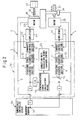
- Fig. 1 is a block diagram of a servo controller of the first embodiment of the present invention.
- This servo controller 1 is composed in substantially the same manner as that of the conventional device except that the servo controller 1 includes a synchronization error calculation means 15 and a correction data calculation means 20 which are characteristic portions of the present invention. Therefore, Fig. 1 shows an outline of the structure of the first embodiment of the present invention.
- the servo controller 1 of this embodiment is applied to a machine tool and connected to a numerical controller 30, which is a host controller, via a common memory not shown.
- a movement command outputted from the numerical controller 30 enters the servo controller 1, and a primary spindle (a first drive axis) and a table of the machine tool are synchronously controlled by servo motors (drive sources) 25, 26 which respectively function as an actuator.
- the numerical controller 30 is connected to a programmable controller, an operation panel and a spherical device which are not shown in the drawing.
- the common memory is a storage device for delivering information, which is outputted from the numerical controller 30, to a processor of the servo controller 1 and on the contrary for delivering various information, which is outputted from the servo controller 1, to the numerical controller 30.
- the servo controller 1 includes: a digital servo circuit 2 having a processor, ROM and RAM; a synchronization error calculation means 15 for calculating a synchronization error of a pair of servo motors 25, 26; and a correction data calculation means 20 for calculating correction data for correcting a positional deviation of the servo motor 26 on the feed side (the slave side) according to the synchronization error.
- a digital servo circuit 2 having a processor, ROM and RAM
- a synchronization error calculation means 15 for calculating a synchronization error of a pair of servo motors 25, 26
- a correction data calculation means 20 for calculating correction data for correcting a positional deviation of the servo motor 26 on the feed side (the slave side) according to the synchronization error.
- the digital servo circuit 2 is substantially the same as that of the prior art.
- the spindle motor 25 for rotating the main spindle not shown and the servo motor 26 on the feed axis for feeding a cutting tool not shown along a feed shaft not shown are subjected to the position loop control 9 and the speed loop control 10 according to a feedback signal.
- the current loop control 11 is also conducted according to a current feedback signal sent from an amplifier 27 such as a transistor inverter.
- the spindle motor 25 and the feed side servo motor 26 are controlled by the servo controller 1 being synchronized with each other.
- the servo motor 26 on the feed side is synchronously controlled so that the tap 32 can be moved in the axial direction at a feed speed which is obtained when a rotary speed of the spindle motor 25 is multiplied by a screw pitch which is a conversion coefficient.
- a moving (position) command per unit time outputted from the numerically control device 30 branches at a branch point 12.
- One movement command is multiplied by a conversion coefficient K of a predetermined ratio.
- the movement command is outputted to the primary spindle side circuit 3 for controlling the spindle motor 25 of the servo controller 1.
- the other movement command is outputted as it is to a feed axis side circuit 4 for controlling the servo motor 26 on the feed side of the servo controller 1.
- a position deviation is found in such a manner that a detection value of the position feedback, which is outputted from a position detector 28 such as a pulse coder for detecting a position of the spindle motor 25, is subtracted from the movement command which has been multiplied by the conversion coefficient K (the position loop control 9). After that, when the time integral calculus is conducted by an integrator ⁇ , the position deviation is found. Next, in the position control section 6, this position deviation is multiplied by a position loop gain so as to find a speed command.
- a detection value of the speed feedback which is outputted from the speed detector for detecting a speed of the spindle motor 25, is subtracted from this speed command so as to find a speed deviation (the speed loop control 10).
- the proportional integral calculus control (PI control) is conducted on this speed deviation so as to find a current command (torque command).
- PI control proportional integral calculus control
- a detection value of the current feedback from the amplifier 27 is subtracted from this current command so as to find a current deviation (the current loop control 11).
- the spindle motor 25 is driven via the amplifier 27, so that a tap 32 and a work are rotated via a speed reduction mechanism not shown in the drawing.
- the position loop control 9, the speed loop control 10 and the current loop control 11 are executed.
- the feed side servo motor 26 is driven via the amplifier 27, and the feed screw 31 is rotated by a speed reduction mechanism not shown, so that the tap 32 can be fed in the axial direction.
- the above servo control conducted according to the digital servo circuit 2 is substantially the same as the conventional control.
- an amount of the position deviation is increased. Accordingly, there is a possibility that it is impossible to sufficiently cope with an increase in the inertia, which is caused when the rigidity of the primary spindle is enhanced, and to cope with an increase in the rotary speed of the primary spindle.
- the device of the present invention includes a synchronization error calculation means 15 and a correction data calculation means 20 in addition to the digital servo circuit 2 so that the present invention can be applied to a machine, the rigidity of the primary spindle of which is high and the speed of the primary spindle of which is also high.
- the synchronization error calculation means 15 is an subtraction means for finding the synchronization error which is a difference between the position deviation of the primary spindle side circuit 3 and the position deviation of the feed side circuit 4.
- the positional deviation of the primary spindle side circuit 3 is found when the positional deviation of the spindle motor 25 is multiplied by the inverse conversion coefficient (K -1 ) so that the positional deviation of the primary spindle side circuit 3 can be converted to a value of the same unit as that of the positional deviation of the feed side circuit 4.
- K -1 the inverse conversion coefficient
- the correction data calculation means 20 receives a synchronization error from the synchronization error calculation means 15 and calculates correction data to correct the positional deviation of the feed side servo motor 26 according to this synchronization error. Then, the correction data calculation means 20 outputs this correction data.
- the correction data is added to the positional deviation of the feed side servo motor 26 at the addition point 13, the processing to make the synchronization error between both the motors 25 and 26 to be zero is completed.
- the feed side servo motor 26 is rotated according to the corrected positional deviation. With respect to the spindle motor 25, the feed side servo motor 26 is rotated while a predetermined rate of timing is being maintained.
- the present embodiment it is possible to adjust a positional deviation of the feed side servo motor 26 according to an amount of the positional deviation of the spindle motor 25. Therefore, even in the case where the inertia of the spindle motor 25 is high or a disturbance is caused by the fluctuation of the cutting force or in the case where the spindle motor 25 is rotated at a high speed, both the motors 25 and 26 can be rotated while a predetermined timing is maintained between them. Therefore, the synchronization error can be reduced and it is possible to machine a work highly accurately and efficiently.
- the servo controller 1A of this embodiment is different from the servo controller 1 of the first embodiment at the point that the correction data calculated by the correction data calculation means 20 can be controlled by learning.
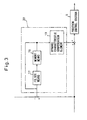
- the correction data calculation means 20 includes: a filter means 17 for restricting a resonance frequency band; a memory means 19 for storing correction data; and a dynamic characteristic compensation element 19 to compensate a phase delay and a gain reduction of the servo motor 26 which is an object to be controlled.
- the memory means 18 has a memory region corresponding to the sampling number. When the work 33 is machined by a predetermined depth of cutting, the memory means 18 accommodates a large number of correction data calculated according to the synchronization error detected by a predetermined sampling time.
- the old correction data accommodated in the memory means is read out at each predetermined sampling time at the next time of machining in which the cutting tool moves in the same path as that of the machining conducted before.
- the correction data, which has been read out in this way, is added to the synchronization error corresponding to the predetermined sampling time found by the synchronization error calculation means 15.
- the data is subjected to filter processing and then accommodated in the memory means 18 as renewed correction data.
- the old data, which has been read out by the memory means 18, is subjected to the compensation of a phase delay and a gain reduction.
- the data is added to the positional deviation at the addition point 13 and the processing is conducted so that the synchronization error of both the motors 25 and 26 can be made to be zero, and the thus processed data is inputted into the position control section 6.
- the correction of the positional deviation and the renewal of the correction data for each machining are repeatedly conducted until the machining program is completed. Due to the foregoing, machining can be highly accurately conducted.
- Fig. 4 is a view showing a variation of the correction data calculation means having a memory means.
- This variation is composed in such a manner that a time to position conversion means 21 and a position to time conversion means 22 for finding correction data corresponding to a sampling position are added to the correction data calculation means 20 shown in Fig. 3.
- the time to position conversion means 21 converts a position deviation at each predetermined sampling position to a position deviation for a predetermined position according to a reference position.
- the position to time conversion means 22 returns correction data at each predetermined position corresponding to each sampling position to correction data corresponding to the time.
- the reference position is a position which can be a reference for synchronizing the feed side servo motor 26 with respect to the spindle motor 25. That is, the reference position is a position feedback (an actual position) detected by the detection means of the spindle motor 25 or the feed side servo motor 26. Alternatively, the reference position is a position command.
- the number of memories (the memory region) of the memory means 18 is found corresponding to the sampling number (2 ⁇ /d), wherein 2n is a machining length of one pass and d is a division width.
- the predetermined position is a grid position previously determined according to the reference position. In this connection, a method of calculating the correction data with reference to position is explained in detail in the specification of application filed before ( JP-A-20005-216135 ). Therefore, a detailed explanation is not given here.
- the learning control is conducted with reference to position. Therefore, in the case where the sampling number is constant, it is possible to make the memory size constant irrespective of the machining speed, that is, the memory size can be reduced.
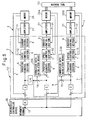
- FIG. 5 is a view showing the third embodiment of the servo controller
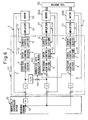
- Fig. 6 is a view showing the fourth embodiment of the servo controller
- Fig. 7 is a view showing the fifth embodiment of the servo controller.
- the machine tool having two or more tandem type feed side servo motors is commonly used.
- this tandem type machine tool as a plurality of servo motors are provided, the load given to each motor can be reduced. Therefore, a body to be driven can be stably driven. Further, the body to be driven can be driven, with respect to the master side spindle motor, with a good following performance. Furthermore, when a plurality of motors are provided, it is possible to increase an output of the machine tool.
- the servo controller 1D of the third embodiment shown in Fig. 5 is different from the servo controller 20 of the first embodiment at the point that the servo controller 1D of the third embodiment includes two correction data calculation means 20C, 20D for correcting the position deviation of the feed side motors 26A, 26B.
- Each correction data calculation means 20C, 20D is the same as the correction data calculation means 20 of the first embodiment.
- the correction data can be calculated.
- the machine tool 50 of the tandem structure can highly accurately machine a work.
- Other points of the structure are the same as those of the first embodiment. Therefore, an explanation is not given here.
- two feed side servo motors 26A, 26B use one correction data calculation means 20C in common. From this viewpoint, the fourth embodiment is different from the third embodiment.
- This correction data calculation means 20C calculates correction data according to the synchronization error between the position deviation of the spindle motor 25 and the position deviation of one feed side motor 26A. When the calculated correction data is added to the position deviation of the two feed side motors 26A, 26B, the spindle motor 25 and the feed side motor can be synchronously controlled.
- This embodiment is preferably used in the case where the two feed side motors 26A, 26B are respectively given the same load.
- the fifth embodiment of the servo controller shown in Fig. 7 two feed side servo motors 26A, 26B use one correction data calculation means 20C in common.
- the fifth embodiment is the same as the fourth embodiment.
- the fifth embodiment is different from the fourth embodiment at the point that two synchronization errors with respect to the individual feed side motors 26A, 26B are used in the correction data calculation means 20C which is used in common.
- the two synchronization errors are weighted by the synchronization error averaging means 40 according to the loads given to the two feed side motors 26A, 26B.
- Weighting is conducted by the synchronization error averaging means 40 as follows.
- a balance point of the two feed side motors 26A, 26B is expressed by the internal ratio n.
- One synchronization error is multiplied by n, and the other synchronization error is multiplied by (1 - n).
- the averaged synchronization error can be expressed by n x ERR (synchronization error) + (1 - n) x ERR (synchronization error).
- the correction error calculation means 20C finds correction data according to the averaged synchronization error.
- the spindle motor 25 and the feed side motor can be controlled synchronously with each other. This embodiment is preferably used for a case in which the two feed side motors 26A, 26B are respectively given a different load.
- the present invention is not limited to the above specific embodiment.
- the synchronization error calculation means 15 is provided in the numerical controller 30, and the correction data can be transferred between the correction data calculation means 20 of the servo controller 1B and the numerical controller 30.
- the memory means 18 may be divided into a predetermined sampling number and it may be commanded that the data is accommodated in a predetermined memory region.
- the memory region can be found by L/T, wherein the same machining pass section is L and the sampling number is T.
- a delay of communication is generated for sending and receiving data especially between the numerical controller 30 and the servo controller 1B.
- the servo controller 1C can includes a switch (switch means) 35 capable of selecting one of the synchronization error and the position deviation of the feed side servo motor 26. According to one data selected by the switch 35, correction data for correcting the position deviation of the feed side servo motor 26 is calculated, and the thus calculated correction data is added to the position data of the feed side servo motor 26. Due to the foregoing, control can be conducted so that an amount of the synchronization error can be reduced. Alternatively, during the synchronizing operation, an amount of the synchronization error can be reduced. During the usual operation in which the synchronizing operation is not conducted, the position deviation can be reduced.
- the correction data calculation means 20B may include a changeover means 35 for changing over a storage region, which conducts learning control, corresponding to an identification number when a synchronization control command is given the identification number. Due to the foregoing, when the storage region is changed over for each command of a different cutting condition, it becomes possible to cope with a different type synchronization command. Accordingly, the flexibility can be enhanced.
- the servo controllers 1D to 1F are applied to the machine tool 50 of the tandem structure having two feed side servo motors 26A, 26B. However, it is possible to apply the servo controllers 1D to 1F to the machine tool of the tandem structure having three or more feed side servo motors 26A, 26B.
Landscapes
- Engineering & Computer Science (AREA)
- Human Computer Interaction (AREA)
- Manufacturing & Machinery (AREA)
- Physics & Mathematics (AREA)
- General Physics & Mathematics (AREA)
- Automation & Control Theory (AREA)
- Computer Hardware Design (AREA)
- Microelectronics & Electronic Packaging (AREA)
- Numerical Control (AREA)
- Control Of Position Or Direction (AREA)
Abstract
Description
- The present invention relates to a servo controller for synchronously controlling a master side drive source and a slave side drive source when the servo controller is applied to a machine in which the same machining is repeatedly conducted and, for example, thread cutting or tapping is repeatedly conducted.
- In general, in the case of machining a male screw on an outer circumferential face of a work, while the work chucked by a primary spindle is being rotated, a predetermined depth of cut is given to a thread cutting tool and the thread cutting tool is linearly moved in the axial direction of the work so as to conduct thread cutting on the work. In this case, in order to prevent the cutting tool from being given an excessively strong cutting force, the depth of cut is given to the cutting tool being divided by several times, that is, cutting of a predetermined depth is repeated by a predetermined number of times so that a perfect thread shape can be formed. In the case of machining a female screw on a work with a tap, the work is fixed onto a table which is moved in X - Y directions, and while the tap attached to the primary spindle is being rotated, the tap is fed in the axial direction of the rotary axis. On the contrary, while the tap is being rotated, the work is fed in the axial direction of the rotary axis. In this way, thread cutting is conducted.
- A feed speed of the cutting tool in the case of machining a male screw and a feed speed of the tap in the case of machining a female screw are determined according to the rotary speeds of the work and tap so that the screw can be continuously formed at a predetermined pitch. That is, a movement command (feed speed) of the cutting tool or the tap, which is linearly moved, and a rotation command (rotary speed) of the rotating work or the rotating tap are maintained at a predetermined ratio. Therefore, in this type of thread cutting or tapping, in order for both drive sources (servo motors) to be synchronously driven at a predetermined ratio, the rotation command and the movement command are given by a numerical controller of a machine tool.
- An example is explained below in which a screw of 1 mm pitch is machined at 6000 min-1. In this case, a position detecting unit of a feed axis driven by one drive source is 10000 pulse/mm and a position detecting unit of a rotary axis driven by the other drive source is 4096 pulse/rev. When consideration is given to a movement command of the feed axis, the rotary axis is rotated one revolution in 10 ms and the feed axis advances 1 mm per revolution. Therefore, the number of pulses becomes 10000 pulse/10 ms. A feed speed of the feed axis becomes 6 m/min. On the contrary, the number of pulses of the rotary axis becomes 4096/10 ms. Accordingly, a ratio of one drive axis to the other drive axis is K = 4096/10000. Accordingly, when a movement command for the drive source to drive the feed axis is multiplied by 4096/10000 and the thus obtained command is made to be a movement command for the drive source to drive the rotary axis, it is possible to machine a screw of 1 mm pitch.
- This is an example in which a pair of driving axes are a rotary axis and a feed axis. However, both of the pair of driving axes may be respectively a feed axis. Alternatively, both of the pair of driving axes may be respectively a rotary axis. That is, the present invention is not limited to the above specific embodiment of the drive axis.
- In this connection, the official gazette of
JP-A-2004-280772 - As described before, in the case where a male screw is machined on an outer circumferential face of a work or a female screw is machined at a predetermined position of a work with a tap, it is necessary that drive sources for respectively driving a rotary axis and a feed axis are synchronized with each other. It is conventional to conduct machining in such a manner that a movement command of one drive source is multiplied by a specific ratio and the other drive source is driven according to thus multiplied movement command.
- However, in the case of machining a male screw or a female screw, as long as the servo characteristics of the drive sources, which are driven synchronously with each other, are the same, the rotary axis and the feed axis have the same positional deviation. Therefore, from the theoretical view point, no synchronization error is caused. However, in the case where inertia of the rotary axis is increased according to an enhancement of the rigidity of the rotary axis or in the case where the rotary axis is rotated at a high speed, the servo characteristic of the rotary axis is inferior to that of the feed axis. Accordingly, a large positional deviation is generated at the time of acceleration and deceleration of the rotary axis. Further, the synchronization error is increased by a cutting disturbance such as a change in the depth of cut of a cutting tool or a shock caused at the time of starting cutting. Furthermore, the synchronization error is increased by the friction. Being affected by the cutting disturbance and friction, the accuracy of machining a screw is deteriorated.
- When the positional deviation of each axis can be made to come close to 0 by conducting learning control on the individual positional deviation of both axes, the synchronization error can be made come close to 0. However, although the inertia is high especially on the rotary axis side, it is necessary to rotate the rotary axis at a high speed. For the above reason, there is a high possibility that the learning control cannot exhibit the effect because it is restricted by the maximum torque of a motor. Explanations are made by referring to an example shown by the paragraph number 0004 as follows. When the rotary speed of the primary spindle is 6000-1, the speed of the feed axis is 6 m/min-1, and the rotation - linearity conversion coefficient (for example, the pitch of a ball screw) is 10 mm/rev. In this case, the rotary speed of the feed axis is 600 min-1, which is 1/10 of the rotary speed of the rotary axis. In this way, even when the axes are driven by the same synchronization command, the speed of the rotary axis must be higher than that of the feed axis by 10 times. Therefore, even when both axes are rotated by the same acceleration and deceleration time constant, a higher torque must be given to the rotary axis, which is very difficult from the practical viewpoint. Therefore, it is reasonable that the synchronous error is learned and controlled by the feed axis because this method is more advantageous from the viewpoints of speed and inertia than the method of learning the positional deviation of both axes.
- An object of the present invention is to provide a servo controller capable of highly accurately and efficiently conducting machining by reducing a synchronization error between a rotary axis side and a feed shaft side even when the inertia of the rotary axis is high or even when the rotary axis is rotated at a high speed.
- In order to accomplish the above object, the present invention provides a servo controller by which a master side drive source for driving one drive axis and a slave side drive source for driving the other drive axis are synchronously controlled, and the servo controller includes a correction data calculating means for calculating correction data to correct positional deviation of the slave side drive source according to the synchronous error, which is a difference between the positional deviation of the master side drive source and the positional deviation of the slave side drive source, wherein the correction data is added to the positional deviation of the slave side drive source.
- According to the present invention described above, the correction data calculating means calculates correction data to correct the positional deviation of the slave side drive source according to the synchronization error, and when this correction error is added to the positional deviation of the slave side drive source, it is possible to conduct control so that the synchronization error can come close to zero. Therefore, an amount of the positional deviation of the slave side motor can be adjusted according to an amount of positional deviation of the master side drive source. That is, in the case where the amount of the positional deviation of the master side drive source is large, correction is conducted so that the amount of the positional deviation of the slave side drive source can be increased. In the case where the amount of the positional deviation of the master side drive source is small, correction is conducted so that the amount of the positional deviation of the slave side drive source can be decreased. Accordingly, the synchronization error can be reduced in the case where the inertia of the master side drive source is high or in the case where the master side drive source is rotated at a high speed or in the case where cutting disturbance is generated by a shock caused when the depth of cut of a cutting tool changes or when the cutting tool starts cutting. Due to the foregoing, machining can be conducted highly accurately and efficiently.
- The present invention provides a servo controller by which a master side drive source for driving one drive axis and a slave side drive source for driving the other drive axis are synchronously controlled, and the servo controller includes: a selection means capable of selecting one of the synchronization error, which is a difference between the positional deviation of the master side drive source and the positional deviation of the slave side drive source, and the positional deviation of the slave side drive source; and a correction data calculating means for calculating correction data to correct positional deviation of the slave side drive source according to one data selected by the selecting means, wherein the correction data is added to the positional deviation of the slave side drive axis and control is conducted so that the positional deviation or the synchronous error can come close to zero.
- According to this invention, in the case where an amount of the positional deviation of the master side drive source is large, the selection means selects the synchronization error, and an amount of the positional deviation of the slave side motor can be adjusted according to an amount of the positional deviation of the master side drive source. Due to the foregoing, the synchronization error can be reduced in the case where the inertia of the master side drive source is high or in the case where the master side drive source is rotated at a high speed or in the case where cutting disturbance is generated by a shock caused when the depth of cut of a cutting tool changes or when the cutting tool starts cutting. Due to the foregoing, machining can be conducted highly accurately and efficiently. On the other hand, in the case where an amount of the positional deviation of the master side drive source is small, the selection means selects the positional deviation of the slave side drive source. According to the amount of this positional deviation, an amount of the positional deviation of the slave side motor can be adjusted. As described above, as one of the synchronous error and the positional deviation can be selected by the selection means, the specification of the servo controller can be changed according to the specification of a machine and the machining accuracy of a product. Accordingly, the flexibility of the servo controller can be enhanced.
- The present invention provides a servo controller applied to a machine having a rotary axis as one drive axis described above and also having a feed axis as the other drive axis described above. According to this invention, the rotary axis is likely to be affected by inertia. Therefore, the positional deviation tends to be increased. However, when the positional deviation of the feed axis is adjusted according to the synchronization error between the rotary axis and the feed axis, the synchronization accuracy of the synchronization control can be enhanced.
- The present invention provides a servo controller applied to a machine for conducting tapping so as to form a female screw in a work. According to this invention, since the machining repeatedly conducted by the machine is tapping, it is possible to reduce the synchronization error of a rigid tap at the time of a normal rotation and at the time of a reverse rotation. Accordingly, it is possible to highly accurately and efficiently conduct machining.
- The present invention provides a servo controller applied to a machine for thread cutting by which a male screw is formed on an outer circumferential face of a work. According to this invention, as the machining repeatedly conducted by the machine is the thread cutting, when a perfect screw is formed with a cutting tool reciprocated by a predetermined number of passes, the repetition accuracy of each pass is enhanced. Accordingly, the occurrence of a positional difference is prevented and a highly accurate screw can be formed.
- The present invention provides a servo controller applied to a machine having two slave side drive sources in which the slave side drive sources respectively drive a first feed axis and a second feed axis of the tandem structure which are arranged in parallel to each other. According to this invention, when two slave side drive sources respectively drive the first feed axis and the second feed axis of the tandem structure, it is possible to reduce a load given to each drive source. Accordingly, the following property of the servo controller can be enhanced. Further, a drive source to be used can be downsized, which can reduce the manufacturing cost.
- The present invention provides a servo controller in which the correction data calculated according to the synchronization error between the master side drive source and one slave side drive source is added to the positional deviation of both the slave side drive sources. According to this invention, the two slave side drive sources can use the correction data calculating means in common. Accordingly, it is possible to provide a simple structure for the servo controller.
- The present invention provides a servo controller in which the correction data calculating means is used by the two slave side drive sources in common and in which two synchronization errors, which are inputted into the correction data calculating means, are weighted by a predetermined internal ratio according a load balance of the first and the second feed axis. According to this invention, in the case where two slave side drive sources use the correction data calculating means in common, the correction data is calculated according to two synchronization errors in which the correction data is weighted. Therefore, it is possible to obtain an averaged correction data for correcting the positional deviation of both the slave side drive sources. Therefore, even when the correction data calculating means is used in common, it is possible to maintain the synchronization accuracy.
- The present invention provides a servo controller further including a storage means for storing the correction data for each period with reference to time so as to conduct the learning control. According to this invention, in the case where the same machining such as thread cutting or tapping is repeatedly conducted, each time the machining is repeated, the synchronization error can be gradually reduced. It is possible to finally converge the synchronization error to zero. Accordingly, the machining can be highly accurately conducted.
- The present invention provides a servo controller further including a storage means for storing the correction data for each sampling with reference to position when the time is converted to the position so as to conduct the learning control. According to this invention, when the learning control is conducted with reference to position, the memory size can be made to be constant without relying on the machining speed.
Therefore, it is possible to save the memory, which is advantageous from an economic viewpoint. - The present invention provides a servo controller in which a movement command sent to the master side drive source and the slave side drive source has an identification number, and the servo controller further includes a changeover means for changing over a storage region for conducting the learning control corresponding to the identification number. According to this invention, the servo controller includes a means for changing over a storage region of the learning control by the identification number. Accordingly, in the case where the synchronization command is different, for example, in the case where a screw depth, a screw pitch or a primary spindle rotary speed is different, the command is different. Therefore, it is necessary to do the learning control once more. However, when the storage region is changed over for each command, it becomes possible to cope with a different type synchronization command. Therefore, the flexibility can be enhanced.
- The above and other objects, characteristics and advantages of the present invention will become more apparent from the following descriptions of embodiments with reference to the accompanying drawings in which:
- Fig. 1 is a block diagram of a servo controller of the first embodiment of the present invention;
- Fig. 2 is a block diagram of a servo controller of the second embodiment of the present invention;
- Fig. 3 is a view showing a correction data calculation means in detail which is shown in Fig. 2;
- Fig. 4 is a view showing a variation of the correction data calculation means;
- Fig. 5 is a block diagram of a servo controller of the third embodiment of the present invention;
- Fig. 6 is a block diagram of a servo controller of the fourth embodiment of the present invention;
- Fig. 7 is a block diagram of a servo controller of the fifth embodiment of the present invention;
- Fig. 8 is a block diagram showing a variation of the servo controller of the second embodiment shown in Fig. 2;
- Fig. 9 is a block diagram showing another variation of the servo controller of the second embodiment shown in Fig. 2; and
- Fig. 10 is a view showing another variation of the correction data calculation means of the servo controller of the second embodiment shown in Fig. 2.
- Referring to the drawings, a specific embodiment of the present invention will be explained in detail as follows. Fig. 1 is a block diagram of a servo controller of the first embodiment of the present invention. This
servo controller 1 is composed in substantially the same manner as that of the conventional device except that theservo controller 1 includes a synchronization error calculation means 15 and a correction data calculation means 20 which are characteristic portions of the present invention. Therefore, Fig. 1 shows an outline of the structure of the first embodiment of the present invention. - The
servo controller 1 of this embodiment is applied to a machine tool and connected to anumerical controller 30, which is a host controller, via a common memory not shown. A movement command outputted from thenumerical controller 30 enters theservo controller 1, and a primary spindle (a first drive axis) and a table of the machine tool are synchronously controlled by servo motors (drive sources) 25, 26 which respectively function as an actuator. - The
numerical controller 30 is connected to a programmable controller, an operation panel and a spherical device which are not shown in the drawing. The common memory is a storage device for delivering information, which is outputted from thenumerical controller 30, to a processor of theservo controller 1 and on the contrary for delivering various information, which is outputted from theservo controller 1, to thenumerical controller 30. - The
servo controller 1 includes: adigital servo circuit 2 having a processor, ROM and RAM; a synchronization error calculation means 15 for calculating a synchronization error of a pair ofservo motors servo motor 26 on the feed side (the slave side) according to the synchronization error. Although explanations of the synchronization error calculation means 15 and the correction data calculation means 20 will be made later, when theservo controller 1 includes both themeans spindle motor 25, which is a servo motor on the master side, with respect to the synchronization error of theservo motor 26 on the feed side is remarkably enhanced. Accordingly, it becomes possible to highly accurately and efficiently conduct machining. - The
digital servo circuit 2 is substantially the same as that of the prior art. In thedigital servo circuit 2, thespindle motor 25 for rotating the main spindle not shown and theservo motor 26 on the feed axis for feeding a cutting tool not shown along a feed shaft not shown are subjected to theposition loop control 9 and thespeed loop control 10 according to a feedback signal. Further, in thedigital servo circuit 2, thecurrent loop control 11 is also conducted according to a current feedback signal sent from anamplifier 27 such as a transistor inverter. - The
spindle motor 25 and the feedside servo motor 26 are controlled by theservo controller 1 being synchronized with each other. For example, in the case where a female screw is formed in awork 33, which is fixed to the table, with atap 32 chucked to a spindle not shown in the drawing, theservo motor 26 on the feed side is synchronously controlled so that thetap 32 can be moved in the axial direction at a feed speed which is obtained when a rotary speed of thespindle motor 25 is multiplied by a screw pitch which is a conversion coefficient. - Referring to Fig. 1, the flow of the
servo controller 1 for thespindle motor 25 and theservo motor 26 on the feed side will be explained below. First, a moving (position) command per unit time outputted from the numerically controldevice 30 branches at abranch point 12. One movement command is multiplied by a conversion coefficient K of a predetermined ratio. Then, the movement command is outputted to the primaryspindle side circuit 3 for controlling thespindle motor 25 of theservo controller 1. The other movement command is outputted as it is to a feedaxis side circuit 4 for controlling theservo motor 26 on the feed side of theservo controller 1. - In the primary
spindle side circuit 3, a position deviation is found in such a manner that a detection value of the position feedback, which is outputted from aposition detector 28 such as a pulse coder for detecting a position of thespindle motor 25, is subtracted from the movement command which has been multiplied by the conversion coefficient K (the position loop control 9). After that, when the time integral calculus is conducted by an integrator Σ, the position deviation is found. Next, in theposition control section 6, this position deviation is multiplied by a position loop gain so as to find a speed command. Successively, in thespeed control section 7, a detection value of the speed feedback, which is outputted from the speed detector for detecting a speed of thespindle motor 25, is subtracted from this speed command so as to find a speed deviation (the speed loop control 10). Then, the proportional integral calculus control (PI control) is conducted on this speed deviation so as to find a current command (torque command). Then, in thecurrent control section 8, a detection value of the current feedback from theamplifier 27 is subtracted from this current command so as to find a current deviation (the current loop control 11). Then, thespindle motor 25 is driven via theamplifier 27, so that atap 32 and a work are rotated via a speed reduction mechanism not shown in the drawing. - In the same manner as that of the primary
spindle side circuit 3, in the feedaxis side circuit 4, theposition loop control 9, thespeed loop control 10 and thecurrent loop control 11 are executed. The feedside servo motor 26 is driven via theamplifier 27, and thefeed screw 31 is rotated by a speed reduction mechanism not shown, so that thetap 32 can be fed in the axial direction. - The above servo control conducted according to the
digital servo circuit 2 is substantially the same as the conventional control. As described before in the description of the prior art, in the control conducted only by thedigital servo circuit 2, an amount of the position deviation is increased. Accordingly, there is a possibility that it is impossible to sufficiently cope with an increase in the inertia, which is caused when the rigidity of the primary spindle is enhanced, and to cope with an increase in the rotary speed of the primary spindle. As a countermeasure for solving the above problems, the device of the present invention includes a synchronization error calculation means 15 and a correction data calculation means 20 in addition to thedigital servo circuit 2 so that the present invention can be applied to a machine, the rigidity of the primary spindle of which is high and the speed of the primary spindle of which is also high. The synchronization error calculation means 15 is an subtraction means for finding the synchronization error which is a difference between the position deviation of the primaryspindle side circuit 3 and the position deviation of thefeed side circuit 4. The positional deviation of the primaryspindle side circuit 3 is found when the positional deviation of thespindle motor 25 is multiplied by the inverse conversion coefficient (K-1) so that the positional deviation of the primaryspindle side circuit 3 can be converted to a value of the same unit as that of the positional deviation of thefeed side circuit 4. When the unit of the primaryspindle side circuit 3 is made to be the same as that of thefeed side circuit 4 as described above, it is possible to find a synchronization error corresponding to a difference between both themotors - The correction data calculation means 20 receives a synchronization error from the synchronization error calculation means 15 and calculates correction data to correct the positional deviation of the feed
side servo motor 26 according to this synchronization error. Then, the correction data calculation means 20 outputs this correction data. When the correction data is added to the positional deviation of the feedside servo motor 26 at theaddition point 13, the processing to make the synchronization error between both themotors side servo motor 26 is rotated according to the corrected positional deviation. With respect to thespindle motor 25, the feedside servo motor 26 is rotated while a predetermined rate of timing is being maintained. - As described above, according to the present embodiment, it is possible to adjust a positional deviation of the feed
side servo motor 26 according to an amount of the positional deviation of thespindle motor 25. Therefore, even in the case where the inertia of thespindle motor 25 is high or a disturbance is caused by the fluctuation of the cutting force or in the case where thespindle motor 25 is rotated at a high speed, both themotors - Next, referring to Figs. 2 and 3, the second embodiment of the servo controller of the present invention will be explained below. The
servo controller 1A of this embodiment is different from theservo controller 1 of the first embodiment at the point that the correction data calculated by the correction data calculation means 20 can be controlled by learning. - The correction data calculation means 20 includes: a filter means 17 for restricting a resonance frequency band; a memory means 19 for storing correction data; and a dynamic
characteristic compensation element 19 to compensate a phase delay and a gain reduction of theservo motor 26 which is an object to be controlled. The memory means 18 has a memory region corresponding to the sampling number. When thework 33 is machined by a predetermined depth of cutting, the memory means 18 accommodates a large number of correction data calculated according to the synchronization error detected by a predetermined sampling time. - The old correction data accommodated in the memory means is read out at each predetermined sampling time at the next time of machining in which the cutting tool moves in the same path as that of the machining conducted before. The correction data, which has been read out in this way, is added to the synchronization error corresponding to the predetermined sampling time found by the synchronization error calculation means 15. The data is subjected to filter processing and then accommodated in the memory means 18 as renewed correction data. On the other hand, the old data, which has been read out by the memory means 18, is subjected to the compensation of a phase delay and a gain reduction. Then, the data is added to the positional deviation at the
addition point 13 and the processing is conducted so that the synchronization error of both themotors position control section 6. The correction of the positional deviation and the renewal of the correction data for each machining are repeatedly conducted until the machining program is completed. Due to the foregoing, machining can be highly accurately conducted. - Fig. 4 is a view showing a variation of the correction data calculation means having a memory means. This variation is composed in such a manner that a time to position conversion means 21 and a position to time conversion means 22 for finding correction data corresponding to a sampling position are added to the correction data calculation means 20 shown in Fig. 3. The time to position conversion means 21 converts a position deviation at each predetermined sampling position to a position deviation for a predetermined position according to a reference position. The position to time conversion means 22 returns correction data at each predetermined position corresponding to each sampling position to correction data corresponding to the time.
- In this case, the reference position is a position which can be a reference for synchronizing the feed
side servo motor 26 with respect to thespindle motor 25. That is, the reference position is a position feedback (an actual position) detected by the detection means of thespindle motor 25 or the feedside servo motor 26. Alternatively, the reference position is a position command. The number of memories (the memory region) of the memory means 18 is found corresponding to the sampling number (2π/d), wherein 2n is a machining length of one pass and d is a division width. In this case, the predetermined position is a grid position previously determined according to the reference position. In this connection, a method of calculating the correction data with reference to position is explained in detail in the specification of application filed before (JP-A-20005-216135 - According to the variation composed described above, the learning control is conducted with reference to position. Therefore, in the case where the sampling number is constant, it is possible to make the memory size constant irrespective of the machining speed, that is, the memory size can be reduced.
- Next, referring to Figs. 5 to 7, another embodiment of the servo controller of the present invention will be explained below. Fig. 5 is a view showing the third embodiment of the servo controller, Fig. 6 is a view showing the fourth embodiment of the servo controller, and Fig. 7 is a view showing the fifth embodiment of the servo controller. These embodiments are common at the point that the embodiments can be applied to a
machine tool 50 having two tandem type feedside servo motors - The machine tool having two or more tandem type feed side servo motors is commonly used. In this tandem type machine tool, as a plurality of servo motors are provided, the load given to each motor can be reduced. Therefore, a body to be driven can be stably driven. Further, the body to be driven can be driven, with respect to the master side spindle motor, with a good following performance. Furthermore, when a plurality of motors are provided, it is possible to increase an output of the machine tool.
- The servo controller 1D of the third embodiment shown in Fig. 5 is different from the
servo controller 20 of the first embodiment at the point that the servo controller 1D of the third embodiment includes two correction data calculation means 20C, 20D for correcting the position deviation of thefeed side motors spindle motor 25 and the position deviation of the individualfeed side motors motors machine tool 50 of the tandem structure can highly accurately machine a work. Other points of the structure are the same as those of the first embodiment. Therefore, an explanation is not given here. - In the fourth embodiment of the servo controller shown in Fig. 6, two feed
side servo motors spindle motor 25 and the position deviation of onefeed side motor 26A. When the calculated correction data is added to the position deviation of the twofeed side motors spindle motor 25 and the feed side motor can be synchronously controlled. This embodiment is preferably used in the case where the twofeed side motors - In the fifth embodiment of the servo controller shown in Fig. 7, two feed
side servo motors feed side motors feed side motors feed side motors - Weighting is conducted by the synchronization error averaging means 40 as follows. A balance point of the two
feed side motors feed side motor 26A is T1 and the torque of thefeed side motor 26B is T2. When the two synchronization errors, which have been weighted, are added, the averaged synchronization errors are calculated. The averaged synchronization error can be expressed by n x ERR (synchronization error) + (1 - n) x ERR (synchronization error). - The correction error calculation means 20C finds correction data according to the averaged synchronization error. When the calculated correction error is added to the position deviation of the two
feed side motors spindle motor 25 and the feed side motor can be controlled synchronously with each other. This embodiment is preferably used for a case in which the twofeed side motors - In this connection, it should be noted that the present invention is not limited to the above specific embodiment. Various variation may be made. For example, as a variation of the second embodiment, as shown in Fig. 8, the synchronization error calculation means 15 is provided in the
numerical controller 30, and the correction data can be transferred between the correction data calculation means 20 of the servo controller 1B and thenumerical controller 30. In this case, simultaneously when the data is transmitted, the memory means 18 may be divided into a predetermined sampling number and it may be commanded that the data is accommodated in a predetermined memory region. The memory region can be found by L/T, wherein the same machining pass section is L and the sampling number is T. A delay of communication is generated for sending and receiving data especially between thenumerical controller 30 and the servo controller 1B. However, when the delay of communication is recovered by advancing at the time of accommodating the data in a predetermined memory region, this delay of communication can be compensated. Due to the foregoing, it becomes unnecessary to provide a circuit for linearly conducting communication in the servo controller 1B. Accordingly, the manufacturing cost can be advantageously reduced. - As shown in Fig. 9, the
servo controller 1C can includes a switch (switch means) 35 capable of selecting one of the synchronization error and the position deviation of the feedside servo motor 26. According to one data selected by theswitch 35, correction data for correcting the position deviation of the feedside servo motor 26 is calculated, and the thus calculated correction data is added to the position data of the feedside servo motor 26. Due to the foregoing, control can be conducted so that an amount of the synchronization error can be reduced. Alternatively, during the synchronizing operation, an amount of the synchronization error can be reduced. During the usual operation in which the synchronizing operation is not conducted, the position deviation can be reduced. - As shown in Fig. 10, the correction data calculation means 20B may include a changeover means 35 for changing over a storage region, which conducts learning control, corresponding to an identification number when a synchronization control command is given the identification number. Due to the foregoing, when the storage region is changed over for each command of a different cutting condition, it becomes possible to cope with a different type synchronization command.
Accordingly, the flexibility can be enhanced. - In the third to the fifth embodiment, the servo controllers 1D to 1F are applied to the
machine tool 50 of the tandem structure having two feedside servo motors side servo motors - Preferred embodiments of the present invention are explained above. However, it should be noted that variations may be made by those skilled in the art without departing from the scope of the claim of the present invention described later.
Claims (11)
- A servo controller (1) for synchronously controlling a master side drive source (25) to drive one drive axis and a slave side drive source (26) to drive the other drive axis,
characterized in that the servo controller (1) comprises:a correction data calculation means (20) for calculating correction data to correct a positional deviation of a slave side drive source (26) according to a synchronization error which is a difference between a positional deviation of a master side drive source (25) and a positional deviation of the slave side drive source (26), whereinthe correction data is added to the positional deviation of the slave side drive source (26). - A servo controller (1C) for synchronously controlling a master side drive source (25) to drive one drive axis and a slave side drive source (26) to drive the other drive axis,
characterized in that the servo controller (1C) comprises:a selection means (35) for selecting one of the synchronization error, which is a difference between a positional deviation of a master side drive source (25) and a positional deviation of the slave side drive source (26), and the positional deviation of the slave side drive source (26); anda correction data calculation means (20) for calculating correction data to correct the positional deviation of the slave side drive source (26) according to one data selected by the selection means (35), whereinthe correction data is added to the positional deviation of the slave side drive shaft (26) so as to make the positional deviation or the synchronization error come close to zero. - A servo controller (1, 1C) according to claim 1 or 2, wherein the servo controller (1, 1C) is applied to a machine tool, the one drive axis of which is a rotary axis and the other drive axis of which is a feed axis.
- A servo controller (1, 1C) according to claim 3, wherein the machine tool conducts tapping for forming a female screw in a work (33).
- A servo controller (1, 1C) according to claim 3, wherein the machine tool conducts thread-cutting for forming a male screw on an outer circumferential face of a work (33).
- A servo controller (1A) according to one of claims 1 to 5, further comprising a storage means (18) for storing the correction data at each predetermined period with reference to time so as to conduct learning control.
- A servo controller (1A) according to one of claims 1 to 5, further comprising a storage means (18) for storing the correction data at each sampling with reference to position so as to conduct learning-control when the time is converted to the position.
- A servo controller (1, 1A, 1B, 1C) according to claim 6 or 7, wherein a movement command sent to the master side drive source and the slave side drive source has an identification number, the servo controller further comprising a changeover means (35) for changing over a storage region, which conducts learning-control, corresponding to the identification number.
- A servo controller (1D) according to one of claims 1 to 8, wherein the servo controller (1D) is applied to a machine tool in which two slave side drive sources (26A, 26B) are provided and the slave side drive sources (26A, 26B) respectively drive a first feed axis of the tandem structure and the second feed axis of the tandem structure which are arranged in parallel to each other.
- A servo controller (1E) according to claim 9, wherein the correction data calculated according to the synchronization error caused between the master side drive source (25) and one slave side drive source (26A) is added to the position deviation of both the slave side drive sources (26A, 26B).
- A servo controller (1F) according to claim 9, wherein the correction data calculation means (20C) is used in common between the two slave side drive sources (26A, 26B), and the two synchronization errors to be inputted into the correction data calculation means (20C) are weighted by a predetermined internal ratio according to a load balance between the first and the second feed axis.
Applications Claiming Priority (2)
| Application Number | Priority Date | Filing Date | Title |
|---|---|---|---|
| JP2005200521 | 2005-07-08 | ||
| JP2006130320A JP4361071B2 (en) | 2005-07-08 | 2006-05-09 | Servo control device |
Publications (2)
| Publication Number | Publication Date |
|---|---|
| EP1742128A1 true EP1742128A1 (en) | 2007-01-10 |
| EP1742128B1 EP1742128B1 (en) | 2012-04-11 |
Family
ID=37312049
Family Applications (1)
| Application Number | Title | Priority Date | Filing Date |
|---|---|---|---|
| EP06014043A Ceased EP1742128B1 (en) | 2005-07-08 | 2006-07-06 | Servo controller |
Country Status (4)
| Country | Link |
|---|---|
| US (1) | US7656106B2 (en) |
| EP (1) | EP1742128B1 (en) |
| JP (1) | JP4361071B2 (en) |
| CN (1) | CN1892523B (en) |
Cited By (5)
| Publication number | Priority date | Publication date | Assignee | Title |
|---|---|---|---|---|
| EP1967924A1 (en) * | 2007-03-08 | 2008-09-10 | Fanuc Ltd | Apparatus for synchronously controlling a plurality of servomotors |
| WO2010063512A3 (en) * | 2008-12-04 | 2011-09-29 | Dr. Johannes Heidenhain Gmbh | Controller structure for multiple mechanically coupled drive units |
| EP2418548A1 (en) * | 2010-08-10 | 2012-02-15 | ABB Research Ltd. | Dual pinion drive system |
| EP3756824A4 (en) * | 2018-03-26 | 2021-10-13 | Siemens Aktiengesellschaft | ROTATING THREAD AUTOMATIC DIAGNOSIS METHOD AND SYSTEM, DATA PROCESSING SYSTEM AND INFORMATION CARRIER |
| EP3823160A4 (en) * | 2018-08-31 | 2022-04-27 | Doosan Machine Tools Co., Ltd. | APPARATUS AND METHOD FOR CONTROLLING MACHINE TOOL RESONANCE SUPPRESSION |
Families Citing this family (57)
| Publication number | Priority date | Publication date | Assignee | Title |
|---|---|---|---|---|
| JP5256619B2 (en) * | 2007-02-23 | 2013-08-07 | ブラザー工業株式会社 | Motor drive device and image forming apparatus |
| JP4323542B2 (en) | 2007-10-22 | 2009-09-02 | ファナック株式会社 | Motor control device with learning control function |
| JP4947214B2 (en) * | 2008-05-13 | 2012-06-06 | 三菱電機株式会社 | Numerical control method and apparatus |
| JP4575508B1 (en) * | 2009-05-20 | 2010-11-04 | ファナック株式会社 | Servo control device for dual position feedback control |
| JP4620159B2 (en) * | 2009-05-21 | 2011-01-26 | ファナック株式会社 | Servo motor control device that controls periodic reciprocating motion |
| US8423186B2 (en) * | 2009-06-30 | 2013-04-16 | Intuitive Surgical Operations, Inc. | Ratcheting for master alignment of a teleoperated minimally-invasive surgical instrument |
| JP4853842B2 (en) | 2010-01-12 | 2012-01-11 | 株式会社安川電機 | Synchronous control device |
| JP5565687B2 (en) * | 2010-06-02 | 2014-08-06 | 株式会社 津々巳電機 | Processing position transplantation method and automatic processing apparatus for executing the method |
| JP5192571B2 (en) * | 2011-07-26 | 2013-05-08 | ファナック株式会社 | Control device for driving one driven body with two electric motors |
| TWI451932B (en) * | 2011-07-27 | 2014-09-11 | Nat Univ Chung Cheng | Locally reinforced learning control for rigid tapping |
| JP5325949B2 (en) * | 2011-08-08 | 2013-10-23 | ファナック株式会社 | Tapping machine |
| JP5314110B2 (en) | 2011-11-25 | 2013-10-16 | ファナック株式会社 | Motor controller for synchronous control of master axis and slave axis |
| JP5973778B2 (en) * | 2012-05-08 | 2016-08-23 | トーヨーエイテック株式会社 | Wire saw device and wire travel control method |
| CN102914968B (en) * | 2012-10-11 | 2015-01-07 | 河南卫华重型机械股份有限公司 | Self-learning synchronous corrosion control system and method |
| WO2014128916A1 (en) * | 2013-02-22 | 2014-08-28 | 三菱電機株式会社 | Numerically controlled apparatus and processing method |
| JP5698777B2 (en) * | 2013-03-13 | 2015-04-08 | ファナック株式会社 | Motor control device for generating preload torque value according to motor acceleration |
| JP5778750B2 (en) | 2013-12-24 | 2015-09-16 | ファナック株式会社 | Control device for injection molding machine having function of reducing synchronization error |
| CN103792880B (en) * | 2014-03-06 | 2016-09-21 | 苏州新代数控设备有限公司 | Promote thread turning speed and the numerical control system of machining accuracy and method thereof |
| EP3119317B1 (en) * | 2014-03-17 | 2020-02-26 | Intuitive Surgical Operations, Inc. | Restoring instrument control input position/orientation during midprocedure restart |
| JP5815784B2 (en) | 2014-04-08 | 2015-11-17 | ファナック株式会社 | Servo controller for reducing synchronization error in synchronous machining |
| JP5897648B2 (en) | 2014-06-17 | 2016-03-30 | ファナック株式会社 | Numerical control device having function of switching gain of position control during synchronous control |
| JP6312548B2 (en) * | 2014-07-31 | 2018-04-18 | ファナック株式会社 | Servo motor control device having self-measuring function and self-monitoring function of machine stiffness |
| JP6412736B2 (en) * | 2014-08-20 | 2018-10-24 | オークマ株式会社 | Position control device |
| JP7049754B2 (en) * | 2015-02-13 | 2022-04-07 | 山洋電気株式会社 | Motor control device |
| JP6496167B2 (en) * | 2015-03-19 | 2019-04-03 | オークマ株式会社 | Tandem position control device |
| JP5987081B1 (en) * | 2015-04-02 | 2016-09-06 | ファナック株式会社 | Servo control device that performs learning control by switching the reference axis |
| JP6088581B2 (en) * | 2015-06-04 | 2017-03-01 | ファナック株式会社 | Machine tool control apparatus and control method for controlling synchronous operation of main shaft and feed shaft |
| JP6154435B2 (en) * | 2015-07-09 | 2017-06-28 | ファナック株式会社 | Servo control device with function to display online automatic adjustment status of control system |
| EP3131202A1 (en) * | 2015-08-11 | 2017-02-15 | Siemens Aktiengesellschaft | Filter switching method for a machine control |
| JP6331225B2 (en) * | 2015-08-19 | 2018-05-30 | 株式会社安川電機 | Motor control device, position control system, and motor control method |
| JP6325504B2 (en) | 2015-10-28 | 2018-05-16 | ファナック株式会社 | Servo control device having a function of automatically adjusting a learning controller |
| WO2017113055A1 (en) * | 2015-12-28 | 2017-07-06 | 深圳配天智能技术研究院有限公司 | Hole tapping method, numerically-controlled machine tool, and numerically-controlled machining device |
| JP2017151528A (en) * | 2016-02-22 | 2017-08-31 | 株式会社リコー | Drive control device, motor drive system, image processing device, and conveyance device |
| JP6380432B2 (en) | 2016-03-14 | 2018-08-29 | オムロン株式会社 | Motor control system, motor control device, program, and recording medium |
| JP6392805B2 (en) | 2016-04-12 | 2018-09-19 | ファナック株式会社 | Servo controller for multiple motor drive |
| KR101808421B1 (en) * | 2016-05-02 | 2017-12-12 | 엘에스산전 주식회사 | Pulse gernerator |
| CN106230325B (en) * | 2016-07-22 | 2018-09-18 | 天津工业大学 | Bi-motor gear train assembly torque balance control method |
| CN106217131B (en) * | 2016-07-27 | 2017-12-22 | 西北工业大学 | Tapping process synchronous error measuring method |
| US10250170B2 (en) | 2016-08-24 | 2019-04-02 | Mitsubishi Electric Corporation | Motor control device |
| JP6412086B2 (en) * | 2016-11-21 | 2018-10-24 | ファナック株式会社 | Numerical controller |
| JP6457563B2 (en) * | 2017-01-24 | 2019-01-23 | ファナック株式会社 | Numerical control device and machine learning device |
| WO2019171444A1 (en) * | 2018-03-05 | 2019-09-12 | 三菱電機株式会社 | Numerical control apparatus and machining method |
| JP6999456B2 (en) * | 2018-03-15 | 2022-01-18 | オークマ株式会社 | Position control system |
| JP6653088B1 (en) * | 2018-08-30 | 2020-02-26 | 株式会社安川電機 | Industrial equipment data collection system and motor control device |
| CN109262086A (en) * | 2018-09-14 | 2019-01-25 | 浙江纳特汽车标准件有限公司 | Servo control tapping method |
| CN109343476B (en) * | 2018-10-08 | 2023-10-13 | 广州数控设备有限公司 | Position gain joint debugging method based on rigid tapping |
| JP7395868B2 (en) * | 2019-08-08 | 2023-12-12 | 株式会社ジェイテクト | Gear processing equipment and gear processing method |
| KR102735885B1 (en) | 2019-12-19 | 2024-11-29 | 주식회사 디엔솔루션즈 | Tandem control system of machine tool and method thereof |
| KR102903406B1 (en) * | 2020-03-05 | 2025-12-22 | 엘에스일렉트릭(주) | Cyclic compensation method of slave axis error during cam-profile motion synchronized to master axis |
| CN115769153B (en) | 2020-07-10 | 2025-04-11 | 发那科株式会社 | Machine tool control device, control method and slave axis control device |
| CN112511043B (en) * | 2020-11-20 | 2022-07-29 | 北京精密机电控制设备研究所 | Synchronous control system and method based on repeated motion multi-axis control |
| DE112021007172T5 (en) * | 2021-06-02 | 2024-01-18 | Fanuc Corporation | Operation control device and program |
| CN117377914B (en) * | 2021-06-02 | 2026-05-01 | 发那科株式会社 | Motion control device and program |
| CN113794404B (en) * | 2021-08-17 | 2024-10-01 | 中国工程物理研究院总体工程研究所 | Phase deviation compensation control method for double-shaft precise centrifugal machine |
| CN117794685A (en) * | 2021-08-24 | 2024-03-29 | 发那科株式会社 | Numerical control devices and storage media |
| CN114706351A (en) * | 2022-03-11 | 2022-07-05 | 上海柏楚数控科技有限公司 | Drive control device and drive control method for multi-axis device, and machine tool device |
| CN115091462B (en) * | 2022-07-18 | 2025-05-27 | 北京易普康达医疗科技有限公司 | A control method for improving the servo stability of the end of a robotic arm |
Citations (6)
| Publication number | Priority date | Publication date | Assignee | Title |
|---|---|---|---|---|
| US4093904A (en) * | 1976-02-04 | 1978-06-06 | Contraves Goerz Corporation | Multi-axis motion generator utilizing feedforward control |
| DE3811183A1 (en) * | 1987-03-31 | 1988-10-27 | Brother Ind Ltd | THREADING MACHINE |
| EP0464496A2 (en) * | 1990-07-05 | 1992-01-08 | Mitsubishi Denki Kabushiki Kaisha | Method for synchronously interlocking feed axes of a lathe |
| DE4432143A1 (en) * | 1994-09-09 | 1996-03-14 | Siemens Ag | Machine tool spindle axis control |
| EP1471400A1 (en) * | 2003-04-21 | 2004-10-27 | Fanuc Ltd | Numerical controller |
| US20040254680A1 (en) * | 2003-03-31 | 2004-12-16 | Kabushiki Kaisha Toshiba | Manipulator and its control apparatus and method |
Family Cites Families (18)
| Publication number | Priority date | Publication date | Assignee | Title |
|---|---|---|---|---|
| US4897660A (en) * | 1986-01-14 | 1990-01-30 | R & D Associates | Structure resonant radar detection apparatus and method |
| JPH03252704A (en) | 1990-03-02 | 1991-11-12 | Mitsubishi Heavy Ind Ltd | Rotational synchronization corrective control system |
| JPH05189019A (en) | 1992-01-09 | 1993-07-30 | Toshiba Mach Co Ltd | Numerical controller for machine tool |
| JP3294900B2 (en) | 1993-04-20 | 2002-06-24 | ファナック株式会社 | Control device |
| JPH06351279A (en) * | 1993-06-11 | 1994-12-22 | Fuji Electric Co Ltd | Synchronous operation system for pulse train input motor |
| KR0185951B1 (en) | 1995-07-04 | 1999-05-15 | 김광호 | A speed control method and apparatus for a motor |
| JP4137321B2 (en) | 1999-05-18 | 2008-08-20 | 三菱電機株式会社 | Mobile device |
| US7148635B1 (en) * | 2005-09-21 | 2006-12-12 | Rockwell Automation Technologies, Inc. | Motor drive with synchronized timing |
| JP2003131712A (en) | 2001-10-22 | 2003-05-09 | Nissan Motor Co Ltd | Multi-axis synchronous control device |
| JP2003181722A (en) | 2001-12-18 | 2003-07-02 | Toyoda Mach Works Ltd | Tapping machining device and tapping machining method |
| JP4043996B2 (en) | 2003-01-20 | 2008-02-06 | ファナック株式会社 | Servo motor drive control device |
| DE10394201T5 (en) * | 2003-04-11 | 2007-03-01 | Mitsubishi Denki K.K. | servo control |
| JP4239772B2 (en) | 2003-09-24 | 2009-03-18 | 株式会社安川電機 | Synchronous operation method and numerical control device |
| JP3898686B2 (en) | 2003-10-20 | 2007-03-28 | ファナック株式会社 | Numerical controller |
| JP2005216135A (en) * | 2004-01-30 | 2005-08-11 | Fanuc Ltd | Threading/tapping controller |
| US7187142B2 (en) * | 2005-05-25 | 2007-03-06 | Rockwell Automation Technologies, Inc. | Motor drive with velocity noise filter |
| US7456599B2 (en) * | 2005-05-31 | 2008-11-25 | Rockwell Automation Technologies, Inc. | Position feedback device with prediction |
| JP2008225533A (en) * | 2007-03-08 | 2008-09-25 | Fanuc Ltd | Servo controller |
-
2006
- 2006-05-09 JP JP2006130320A patent/JP4361071B2/en not_active Expired - Fee Related
- 2006-07-06 EP EP06014043A patent/EP1742128B1/en not_active Ceased
- 2006-07-07 US US11/482,011 patent/US7656106B2/en not_active Expired - Fee Related
- 2006-07-10 CN CN2006101017819A patent/CN1892523B/en not_active Expired - Fee Related
Patent Citations (6)
| Publication number | Priority date | Publication date | Assignee | Title |
|---|---|---|---|---|
| US4093904A (en) * | 1976-02-04 | 1978-06-06 | Contraves Goerz Corporation | Multi-axis motion generator utilizing feedforward control |
| DE3811183A1 (en) * | 1987-03-31 | 1988-10-27 | Brother Ind Ltd | THREADING MACHINE |
| EP0464496A2 (en) * | 1990-07-05 | 1992-01-08 | Mitsubishi Denki Kabushiki Kaisha | Method for synchronously interlocking feed axes of a lathe |
| DE4432143A1 (en) * | 1994-09-09 | 1996-03-14 | Siemens Ag | Machine tool spindle axis control |
| US20040254680A1 (en) * | 2003-03-31 | 2004-12-16 | Kabushiki Kaisha Toshiba | Manipulator and its control apparatus and method |
| EP1471400A1 (en) * | 2003-04-21 | 2004-10-27 | Fanuc Ltd | Numerical controller |
Cited By (12)
| Publication number | Priority date | Publication date | Assignee | Title |
|---|---|---|---|---|
| EP1967924A1 (en) * | 2007-03-08 | 2008-09-10 | Fanuc Ltd | Apparatus for synchronously controlling a plurality of servomotors |
| WO2010063512A3 (en) * | 2008-12-04 | 2011-09-29 | Dr. Johannes Heidenhain Gmbh | Controller structure for multiple mechanically coupled drive units |
| CN102282752A (en) * | 2008-12-04 | 2011-12-14 | 约翰尼斯海登海恩博士股份有限公司 | Controller structure for multiple mechanically coupled drive units |
| CN102282752B (en) * | 2008-12-04 | 2014-10-22 | 约翰内斯﹒海德汉博士有限公司 | Regulator structure for multiple mechanically coupled drive units |
| US9106169B2 (en) | 2008-12-04 | 2015-08-11 | Dr. Johannes Heidenhain Gmbh | Controller structure for multiple mechanically coupled drive units |
| EP2418548A1 (en) * | 2010-08-10 | 2012-02-15 | ABB Research Ltd. | Dual pinion drive system |
| WO2012020031A3 (en) * | 2010-08-10 | 2012-04-12 | Abb Research Ltd | Dual pinion drive system |
| US8866418B2 (en) | 2010-08-10 | 2014-10-21 | Abb Research Ltd | Dual pinion drive system |
| RU2540828C2 (en) * | 2010-08-10 | 2015-02-10 | Абб Рисерч Лтд | Dual pinion drive system |
| EP3756824A4 (en) * | 2018-03-26 | 2021-10-13 | Siemens Aktiengesellschaft | ROTATING THREAD AUTOMATIC DIAGNOSIS METHOD AND SYSTEM, DATA PROCESSING SYSTEM AND INFORMATION CARRIER |
| US11550294B2 (en) | 2018-03-26 | 2023-01-10 | Siemens Aktiengesellschaft | Automatic diagnosis method and system for thread turning, data processing system and storage medium |
| EP3823160A4 (en) * | 2018-08-31 | 2022-04-27 | Doosan Machine Tools Co., Ltd. | APPARATUS AND METHOD FOR CONTROLLING MACHINE TOOL RESONANCE SUPPRESSION |
Also Published As
| Publication number | Publication date |
|---|---|
| US7656106B2 (en) | 2010-02-02 |
| CN1892523B (en) | 2010-10-27 |
| US20070007926A1 (en) | 2007-01-11 |
| JP4361071B2 (en) | 2009-11-11 |
| JP2007042068A (en) | 2007-02-15 |
| EP1742128B1 (en) | 2012-04-11 |
| CN1892523A (en) | 2007-01-10 |
Similar Documents
| Publication | Publication Date | Title |
|---|---|---|
| US7656106B2 (en) | Servo controller | |
| US20080218116A1 (en) | Servo controller | |
| US7215089B2 (en) | Threading/tapping control apparatus | |
| US8676358B2 (en) | Numerical control method and numerical control device | |
| US8299743B2 (en) | Machine tool and controlling method thereof | |
| EP0557530A1 (en) | Numerical control device | |
| US20180297163A1 (en) | Control device for machine tool performing oscillation cutting | |
| US5175680A (en) | Synchronizing control apparatus | |
| EP0464496B1 (en) | Method for synchronously interlocking feed axes of a lathe | |
| US20050228533A1 (en) | Machining time calculating apparatus | |
| US6823235B2 (en) | Controller for machining gears | |
| US5930142A (en) | Numerical control system with hierarchical interpolation functions | |
| US7613541B2 (en) | Thread control method and system therefor | |
| US5027680A (en) | Machine tool with two spindles | |
| US5367238A (en) | Backlash acceleration control method | |
| US6628097B2 (en) | Machine tool and control method therefor | |
| JPH04323705A (en) | Synchronous repeat control system for rotation axis | |
| US6969961B2 (en) | Method for controlling a rotation speed of a slave drive, a corresponding controller and a corresponding machine | |
| US20230176547A1 (en) | Numerical controller for controlling tapping on basis of processing program | |
| JP2588610B2 (en) | Synchronous tapping control method | |
| EP0091320A1 (en) | Turning control apparatus and method | |
| JPH0887312A (en) | Cylinder interpolation system | |
| JPH05189019A (en) | Numerical controller for machine tool | |
| JPH0546236A (en) | Numerical controller | |
| JPH0436807A (en) | Numerical controller containing backlash correcting function |
Legal Events
| Date | Code | Title | Description |
|---|---|---|---|
| PUAI | Public reference made under article 153(3) epc to a published international application that has entered the european phase |
Free format text: ORIGINAL CODE: 0009012 |
|
| AK | Designated contracting states |
Kind code of ref document: A1 Designated state(s): AT BE BG CH CY CZ DE DK EE ES FI FR GB GR HU IE IS IT LI LT LU LV MC NL PL PT RO SE SI SK TR |
|
| AX | Request for extension of the european patent |
Extension state: AL BA HR MK YU |
|
| 17P | Request for examination filed |
Effective date: 20070709 |
|
| AKX | Designation fees paid |
Designated state(s): DE |
|
| 17Q | First examination report despatched |
Effective date: 20081211 |
|
| RAP1 | Party data changed (applicant data changed or rights of an application transferred) |
Owner name: FANUC CORPORATION |
|
| GRAP | Despatch of communication of intention to grant a patent |
Free format text: ORIGINAL CODE: EPIDOSNIGR1 |
|
| RIN1 | Information on inventor provided before grant (corrected) |
Inventor name: IWASHITA, YASUSUKE Inventor name: TOYOZAWA, YUKIO Inventor name: MAEDA, KAZUOMI |
|
| GRAS | Grant fee paid |
Free format text: ORIGINAL CODE: EPIDOSNIGR3 |
|
| GRAA | (expected) grant |
Free format text: ORIGINAL CODE: 0009210 |
|
| AK | Designated contracting states |
Kind code of ref document: B1 Designated state(s): DE |
|
| REG | Reference to a national code |
Ref country code: DE Ref legal event code: R096 Ref document number: 602006028690 Country of ref document: DE Effective date: 20120606 |
|
| PLBE | No opposition filed within time limit |
Free format text: ORIGINAL CODE: 0009261 |
|
| STAA | Information on the status of an ep patent application or granted ep patent |
Free format text: STATUS: NO OPPOSITION FILED WITHIN TIME LIMIT |
|
| 26N | No opposition filed |
Effective date: 20130114 |
|
| REG | Reference to a national code |
Ref country code: DE Ref legal event code: R097 Ref document number: 602006028690 Country of ref document: DE Effective date: 20130114 |
|
| PGFP | Annual fee paid to national office [announced via postgrant information from national office to epo] |
Ref country code: DE Payment date: 20200624 Year of fee payment: 15 |
|
| REG | Reference to a national code |
Ref country code: DE Ref legal event code: R119 Ref document number: 602006028690 Country of ref document: DE |
|
| PG25 | Lapsed in a contracting state [announced via postgrant information from national office to epo] |
Ref country code: DE Free format text: LAPSE BECAUSE OF NON-PAYMENT OF DUE FEES Effective date: 20220201 |