EP1742030A2 - Transducer for measuring a shaft dynamic behaviour - Google Patents
Transducer for measuring a shaft dynamic behaviour Download PDFInfo
- Publication number
- EP1742030A2 EP1742030A2 EP06076662A EP06076662A EP1742030A2 EP 1742030 A2 EP1742030 A2 EP 1742030A2 EP 06076662 A EP06076662 A EP 06076662A EP 06076662 A EP06076662 A EP 06076662A EP 1742030 A2 EP1742030 A2 EP 1742030A2
- Authority
- EP
- European Patent Office
- Prior art keywords
- sensor
- transducer
- arcuate
- ring
- inner member
- Prior art date
- Legal status (The legal status is an assumption and is not a legal conclusion. Google has not performed a legal analysis and makes no representation as to the accuracy of the status listed.)
- Granted
Links
Images



Classifications
-
- G—PHYSICS
- G01—MEASURING; TESTING
- G01L—MEASURING FORCE, STRESS, TORQUE, WORK, MECHANICAL POWER, MECHANICAL EFFICIENCY, OR FLUID PRESSURE
- G01L1/00—Measuring force or stress, in general
- G01L1/20—Measuring force or stress, in general by measuring variations in ohmic resistance of solid materials or of electrically-conductive fluids; by making use of electrokinetic cells, i.e. liquid-containing cells wherein an electrical potential is produced or varied upon the application of stress
- G01L1/22—Measuring force or stress, in general by measuring variations in ohmic resistance of solid materials or of electrically-conductive fluids; by making use of electrokinetic cells, i.e. liquid-containing cells wherein an electrical potential is produced or varied upon the application of stress using resistance strain gauges
-
- G—PHYSICS
- G01—MEASURING; TESTING
- G01L—MEASURING FORCE, STRESS, TORQUE, WORK, MECHANICAL POWER, MECHANICAL EFFICIENCY, OR FLUID PRESSURE
- G01L5/00—Apparatus for, or methods of, measuring force, work, mechanical power, or torque, specially adapted for specific purposes
- G01L5/04—Apparatus for, or methods of, measuring force, work, mechanical power, or torque, specially adapted for specific purposes for measuring tension in flexible members, e.g. ropes, cables, wires, threads, belts or bands
- G01L5/10—Apparatus for, or methods of, measuring force, work, mechanical power, or torque, specially adapted for specific purposes for measuring tension in flexible members, e.g. ropes, cables, wires, threads, belts or bands using electrical means
-
- G—PHYSICS
- G01—MEASURING; TESTING
- G01D—MEASURING NOT SPECIALLY ADAPTED FOR A SPECIFIC VARIABLE; ARRANGEMENTS FOR MEASURING TWO OR MORE VARIABLES NOT COVERED IN A SINGLE OTHER SUBCLASS; TARIFF METERING APPARATUS; MEASURING OR TESTING NOT OTHERWISE PROVIDED FOR
- G01D5/00—Mechanical means for transferring the output of a sensing member; Means for converting the output of a sensing member to another variable where the form or nature of the sensing member does not constrain the means for converting; Transducers not specially adapted for a specific variable
-
- G—PHYSICS
- G01—MEASURING; TESTING
- G01L—MEASURING FORCE, STRESS, TORQUE, WORK, MECHANICAL POWER, MECHANICAL EFFICIENCY, OR FLUID PRESSURE
- G01L1/00—Measuring force or stress, in general
- G01L1/20—Measuring force or stress, in general by measuring variations in ohmic resistance of solid materials or of electrically-conductive fluids; by making use of electrokinetic cells, i.e. liquid-containing cells wherein an electrical potential is produced or varied upon the application of stress
- G01L1/22—Measuring force or stress, in general by measuring variations in ohmic resistance of solid materials or of electrically-conductive fluids; by making use of electrokinetic cells, i.e. liquid-containing cells wherein an electrical potential is produced or varied upon the application of stress using resistance strain gauges
- G01L1/2206—Special supports with preselected places to mount the resistance strain gauges; Mounting of supports
- G01L1/2231—Special supports with preselected places to mount the resistance strain gauges; Mounting of supports the supports being disc- or ring-shaped, adapted for measuring a force along a single direction
- G01L1/2237—Special supports with preselected places to mount the resistance strain gauges; Mounting of supports the supports being disc- or ring-shaped, adapted for measuring a force along a single direction the direction being perpendicular to the central axis
Definitions
- the prior art transducers are not compact nor can they be used as an integral part of a system pulley.
- the inventive transducer can be machined from a single piece of material, such as metal.
- the device may also be cast from a suitable material such as plastic or ceramic depending upon the load to be born by the transducer.
Landscapes
- Physics & Mathematics (AREA)
- General Physics & Mathematics (AREA)
- Force Measurement Appropriate To Specific Purposes (AREA)
- Measurement Of Force In General (AREA)
- Measurement Of Length, Angles, Or The Like Using Electric Or Magnetic Means (AREA)
- Devices For Conveying Motion By Means Of Endless Flexible Members (AREA)
- Shafts, Cranks, Connecting Bars, And Related Bearings (AREA)
- Working-Up Tar And Pitch (AREA)
- Organic Low-Molecular-Weight Compounds And Preparation Thereof (AREA)
- Steroid Compounds (AREA)
Abstract
Description
- The invention relates to a transducer, and more particularly to a transducer for measuring a shaft dynamic behavior having concentric members supporting an arcuate sensor member between them.
- Various strain measuring devices are known. Among the known devices are dual beam sensing members which include spaced end wall members connected integrally by parallel spaced beam members, which beam members are relatively flexible or bendable in one direction only. One of the end walls is generally attached to a support structure and the other end wall is operatively or directly attached to a shaft.
- Other devices are known which provide a cantilever connection between a shaft member and a load sensor device. The cantilever nature of the connection serves to increase a width or thickness of the device, thereby increasing the space necessary to accommodate the device.
- Representative of the art is
U.S. patent no. 4,899,599 to Eddens (1990 ) which discloses a strain sensor device for measuring tension on a web or strand member including a frame member, a shaft member extending from the frame member and having a web or strand engaging member mounted thereon, the strain sensor device supporting one portion of the shaft on the frame member. -
US 4,015,468 is exemplary of the art. This document discloses a device for measurement of the radial force sustained by a rotary organ, constituted by at least one detector of the deformation in the direction of the radial force to be measured in at least one of the elements constituted by two coaxial annular organs and a connecting one of the annular organs to a support. -
DE 36 03 187 is further exemplary of the art. This document discloses a device for measuring linear force, in particular for measuring tension in a running web, having at least one measuring ring which is exposed to a radial force in a steady bearing and exhibits at least one double bending beam which can be deformed under the force, and having at least one strain gauge mounted on the double bending beam by means of which the stresses occurring during deformation of the double bending beam can be determined. -
US 4,281,539 is further exemplary of the art. This document discloses a measuring apparatus for measuring forces acting upon a bearing, particularly the radial forces, effective at a roller bearing. The measuring apparatus essentially comprises two rings, typically formed of metal, which are concentrically interconnected by means of a web. The roller bearing transmits the force to be measured to one of the rings, whereas the other ring is fixed. The one ring rocks or moves in relation to the fixed ring and the deformation prevailing at the web is electrically measured and indicated in a display or indicator device. The measuring apparatus serves for measuring the tension in belts, bands, and the like. - The prior art transducers are not compact nor can they be used as an integral part of a system pulley.
- What is needed is a transducer that comprises concentric and coplanar members supporting an arcuate sensor member disposed between them. What is needed is a transducer that can be contained within a pulley. What is needed is a transducer that comprises concentric and coplanar members supporting an arcuate sensor member disposed between them and having a load self-aligning feature. The present invention meets these needs.
- The primary aspect of the invention is to provide a transducer that comprises concentric and coplanar members supporting an arcuate sensor member disposed between them.
- Another aspect of the invention is to provide a transducer that can be contained within a pulley.
- Another aspect of the invention is to provide a transducer that comprises concentric and coplanar members supporting an arcuate sensor member disposed between them and having a load self-aligning feature.
- Other aspects of the invention will be pointed out or made obvious by the following description of the invention and the accompanying drawings.
- The invention comprises a transducer for detecting a shaft dynamic behavior. The transducer comprises an arcuate sensor member supported between an inner member and an outer member. At least one strain gage is attached to a surface of the arcuate sensor member to detect a surface strain caused by a shaft dynamic behavior. The inner member, outer member and arcuate sensor member are substantially coplanar. The inner member comprises a means for attaching the transducer to a mounting surface. The inner member may also comprise a self-aligning feature to optimize a sensor sensitivity.
- The accompanying drawings, which are incorporated in and form a part of the specification, illustrate preferred embodiments of the present invention, and together with a description, serve to explain the principles of the invention.
- Fig. 1 is a perspective view of the transducer.
- Fig. 2 is a perspective view of the transducer.
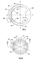
- Fig. 3 is a plan view of the transducer sensor ring.
- Fig. 4A is a plan view of the transducer.
- Fig. 4B is a cross-sectional view of Fig. 4A at line B-B.
- Fig. 4C is a side view at 4C-4C in Fig. 4B.
- Fig. 5 is a perspective exploded view of the transducer.
- Fig. 6 is a partial plan view of the self-aligning portion.
- Fig. 7 is a partial plan view of the self-aligning portion.
- Fig. 1 is a perspective view of the transducer. The transducer is relatively compact and may be used in a pulley to measure a shaft load or shaft dynamic behavior. This includes measuring a hubload and thereby a belt tension. A hubload is a load imparted to a pulley and its shaft by a belt tension in a belt drive system. The transducer may also be used to measure a shaft vibration.
-
Transducer 100 generally comprises an arcuate inner member orhub ring 101,sensor ring 102 and arcuate outer member orouter ring 103.Hub ring 101 comprises abore 104 which acts as a means for attaching the transducer to a mounting surface. A fastener such as a bolt engageshub ring 101 throughbore 104 to connect the transducer to a mounting surface.Hub ring 101 is relatively rigid to provide a firm means of connecting the transducer to a mounting surface.Hub ring 101 may also comprise an integral shaft for attaching the hub ring to a mounting surface.Hub ring 101 is connected tosensor ring 102 by connecting portion ormember 108. -
Sensor ring 102 is connected betweenhub ring 101 andouter ring 103.Sensor ring 102 has an arcuate shape which concentrically cooperates with the arcuate shape ofhub ring 101 andouter ring 103. The concentric relationship between the hub ring, sensor ring and outer ring allows the inventive transducer to have a minimal diameter for better use in confined areas, such as in a pulley. -
Slot 510 is disposed betweensensor ring 102 andouter ring 103.Slot 511 is disposed betweensensor ring 102 andinner ring 101. Underload sensor ring 102 deforms to become elongated or elliptically shaped, having a major axis in direction A-A and a minor axis in direction B-B, see Fig. 3. A width ofslot 511 is determined by a desired total deformation ofsensor ring 102 in direction B-B when under load. A width ofslot 511 is also a function of the thickness T ofsensor ring 102. Thickness T is determined by the dynamic conditions to which the sensor ring is exposed. - At least one strain gage is attached to the sensor ring as described in Fig. 3. A hubload force vector is represented by
vector 600.Sensor ring 102 is sufficiently flexible to cause a surface strain to be realized at a strain gage location upon application of a hubload to the hub ring.Sensor ring 102 is connected through arcuate connectingmembers 512 toouter ring 103 andportion 107.Portion 107 and connectingmember 108 are disposed on substantially opposing sides ofsensor ring 102. Connectingsensor ring 102 toouter ring 103 atmembers 512 enhances a deformation ofsensor ring 102, and therefore enhances surface strains insensor ring 102 when subjected to ahubload force 600 along axis A-A. Althoughvector 600 is showing having a particular direction, the transducer is capable of detecting loads having vectors in any direction. Of course, an overall sensitivity may be affected depending upon the spatial relationship betweenvector 600 and the strain gage(s) position with respect thereto. - Each
member 512 partially deforms in conjunction with'sensor ring 102 when the transducer is under load.Members 512 have a predetermined spring rate that is a function of the dynamic loading to be borne by the transducer, and more particularly, bysensor ring 102. The predetermined spring rate in turn determines an arcuate form of eachmember 512. - One can appreciate that during
operation sensor ring 102 will be constantly subjected to vibrations and cyclic loading. This will in turn impose stresses on the connection betweensensor ring 102 andouter ring 103. Hence, the arcuate form ofmembers 512 enhances a transducer operating life by distributing and dispersing, thereby reducing, stress risers that might otherwise be present at a connection between thesensor ring 102 and theouter ring 103. This, in turn, minimizes potential fatigue cracking that may otherwise be caused by stress risers at the connection. -
Apertures outer ring 103 are used to facilitate installation ofstrain gages sensor ring 102, see Fig. 3. -
Bracket 500 may be used to accept a strain-gage signal conditioner.Bracket 500 is attached toouter ring 103. Bracket may be formed or cast as an integral part ofouter ring 103 as well. -
Outer ring 103 provides structural strength to the device as well as provides a means for engaging the transducer to a bearing and pulley.Outer ring 103 is press fit into a pulley bearing, which bearing is in turn engaged with a pulley for engaging a belt.Outer ring 103 is sufficiently rigid to permit rotational operation of a pulley about the transducer in a belt drive system. -
Hub ring 101,sensor ring 102, andouter ring 103 are substantially coplanar. More particularly, each of the rings is concentrically nested within the other. Nesting the rings reduces a thickness of the inventive device to a minimum, thereby allowing use of the transducer in a pulley, for example, in an existing vehicle front end accessory drive where equipment space may be confined. The inventive transducer can be used to replace an existing pulley in a belt drive system, thus allowing retrofit for instrument installation with little or no modification to an existing system. The transducer may also be used in a tensioner between a tensioner pulley and tensioner arm on a tensioner pulley shaft in order to measure a shaft dynamic behavior or a tensioner arm dynamic behavior. - In the preferred embodiment the inventive transducer can be machined from a single piece of material, such as metal. The device may also be cast from a suitable material such as plastic or ceramic depending upon the load to be born by the transducer.
- In another embodiment, it may comprise three pieces, i.e., hub ring, sensor ring, and outer ring joined by adhesives or screws, see Fig. 4a. In an embodiment, the hub ring and the outer ring comprise a ceramic material and the sensor ring comprises a metallic material. In yet another embodiment the hub ring and the outer ring may comprise a plastic material in particularly low load applications. The plastic need only have a sufficient modulus and have a sufficient resistance to the operating temperature of the engine to which it is mounted.
- In yet another embodiment, the sensor ring and the outer ring comprise a single machined piece, with the hub ring attached by screws or adhesives to the sensor ring. In this embodiment the sensor ring and outer ring may comprise a metallic material and the hub ring may comprise a ceramic material. The hub ring may also comprise a plastic material in a relatively low load application. The plastic need only have a sufficient modulus and have a sufficient resistance to the operating temperature of the engine to which it is mounted.
- Fig. 2 is a perspective view of the transducer.
Transducer 100 is shown contained within apulley 200. A bearing orbearings 205 are pressed onto the outside ofouter ring 103 to occupy an annular space betweenouter ring 103 andpulley 200.Bracket 500 is attached totransducer 100 withfasteners - Fig. 3 is a plan view of the transducer sensor ring.
Sensor ring 102 is shown withstrain gages wires Wires bracket 500 for connection to an instrument lead wire.Strain gages sensor ring 102 throughapertures - Fig. 4A is a plan view of the transducer. This is the embodiment using a
separate hub ring 101,sensor ring 102 andouter ring 103 as described elsewhere herein.Sensor ring 102 is fastened toouter ring 103 usingscrews Hub ring 101 is fastened tosensor ring 102 usingscrews Screws - Fig. 4B is a cross-sectional view of Fig. 4A at
line 4B-4B.Screws sensor ring 102 toouter ring 103.Bracket 500 provides a means to connect the strain gage wires to an instrument lead wire as described elsewhere herein. - Fig. 4C is a side view at 4C-4C in Fig. 4B.
Screws outer ring 103 tosensor ring 102. - Fig. 5 is a perspective exploded view of the transducer.
Bearings 205 are pressed onouter ring 103 oftransducer 100.Pulley 200 is pressed ontobearings 205. - Fig. 6 is a partial plan view of the self-aligning portion. In order to optimize a sensitivity of the transducer, it is desirable that the sensor ring be disposed to the
hubload vector 600 such thatvector 600 aligns with axis A-A, thereby aligning the strain gages with an axis B-B, see Fig. 3. This can be accomplished using a self-aligningmember 700. - More particularly, an eccentric self-aligning
member 700 is disposed in inner ring bore 104. By way of example and not of limitation,eccentric member 700 is press fit intobore 104, One can also appreciate thatmember 700 may also simply comprise an integral part of arcuateinner member 101, namely, arcuate inner member comprises abore 701 having acenter 705 which is not aligned with a transducer geometric center. -
Eccentric member 700 comprises abore 701.Center 705 ofbore 701 is eccentrically disposed a distance from an eccentric membergeometric center 704. Eccentric membergeometric center 704 also coincides with a transducer geometric center and sensor ring geometric center. Bearing 702 is pressed intobore 701. Afastening member 703, such as a bolt, projects through and attaches bearing 702, and thereby the transducer, to a mounting surface (not shown). By action of bearing 702 the transducer is freely rotatable about fasteningmember 703. - In an exemplary situation, a
hubload vector 600 is shown acting upon the transducer. The hubload is caused by a belt BT having a tension. In theexemplary configuration vector 600 is initially laterally offset frombore center 705 by a distance (D). Immediately upon application of ahubload 600, the self-aligning feature ofmember 700 operates to properly align the transducer. More particularly, distance (D) acts as a lever arm which causes a torque to be applied toeccentric member 700. The torque causeseccentric member 700, and therebytransducer 100 andsensor ring 102, to rotate about bearing 702 untilvector 600 aligns withcenter 705, thereby eliminating the self-aligning torque and restoring equilibrium. This manner of operation of self-alignment applies regardless of the direction ofvector 600. - Fig. 7 is a partial plan view of the self-aligning portion.
Vector 600 is aligned withbore center 705. This orientation results instrain gages - One can appreciate that the transducer can operate with or without the self-aligning
member 700 as described in Figs. 6 and 7. Use of the self-aligningmember 700 depends upon a desired sensitivity for the transducer. This may also depend in part upon a range of movement ofvector 600 during operation. The sensitivity of the transducer is a function of the alignment of the strain gage(s) with aload vector 600. For example, if the inventive transducer is used with an idler with a narrow range of directions forvector 600, the need for the self-aligning member may be less important. In the alternative, where the transducer is used on a tensioner having a relatively large range of movement caused by a tensioner arm movement, use of the self-aligning member is advantageous to maintain a desired sensitivity for the transducer. - Although forms of the invention have been described herein, it will be obvious to those skilled in the art that variations may be made in the construction and relation of parts without departing from the spirit and scope of the invention described herein.
Claims (6)
- A sensor comprising;
an arcuate outer member;
an arcuate inner member;
an arcuate sensor member for sensing a strain;
the arcuate sensor member connected between the arcuate outer member and the arcuate inner member;
at least one strain gage disposed on a surface of the arcuate sensor member;
the arcuate outer member and the arcuate inner member are coplanar; and
the arcuate inner member comprising a bore offset from a sensor center, the sensor thereby eccentrically rotatable about the sensor center. - The sensor as in claim 1 wherein the arcuate sensor member and the arcuate outer member and the arcuate inner member are coplanar.
- The sensor as in claim 1 wherein the arcuate inner member describes a bore.
- The sensor as in claim 1 wherein the arcuate outer member and the arcuate inner member are concentric.
- The sensor as in claim 1 further comprising an arcuate connecting member between the arcuate sensor ring and the arcuate outer ring.
- The sensor as in claim 1 further comprising a bearing disposed in the offset bore for engaging a fastener.
Applications Claiming Priority (2)
| Application Number | Priority Date | Filing Date | Title |
|---|---|---|---|
| US10/262,035 US7021159B2 (en) | 2002-09-30 | 2002-09-30 | Transducer |
| EP03756830A EP1546669B1 (en) | 2002-09-30 | 2003-09-16 | Transducer for measuring a shaft dynamic behavior |
Related Parent Applications (1)
| Application Number | Title | Priority Date | Filing Date |
|---|---|---|---|
| EP03756830A Division EP1546669B1 (en) | 2002-09-30 | 2003-09-16 | Transducer for measuring a shaft dynamic behavior |
Publications (3)
| Publication Number | Publication Date |
|---|---|
| EP1742030A2 true EP1742030A2 (en) | 2007-01-10 |
| EP1742030A3 EP1742030A3 (en) | 2009-02-18 |
| EP1742030B1 EP1742030B1 (en) | 2015-08-19 |
Family
ID=32030124
Family Applications (2)
| Application Number | Title | Priority Date | Filing Date |
|---|---|---|---|
| EP06076662.3A Expired - Lifetime EP1742030B1 (en) | 2002-09-30 | 2003-09-16 | Transducer for measuring a shaft dynamic behavior |
| EP03756830A Expired - Lifetime EP1546669B1 (en) | 2002-09-30 | 2003-09-16 | Transducer for measuring a shaft dynamic behavior |
Family Applications After (1)
| Application Number | Title | Priority Date | Filing Date |
|---|---|---|---|
| EP03756830A Expired - Lifetime EP1546669B1 (en) | 2002-09-30 | 2003-09-16 | Transducer for measuring a shaft dynamic behavior |
Country Status (15)
| Country | Link |
|---|---|
| US (2) | US7021159B2 (en) |
| EP (2) | EP1742030B1 (en) |
| JP (1) | JP4242345B2 (en) |
| KR (1) | KR20050061494A (en) |
| CN (1) | CN100368787C (en) |
| AT (1) | ATE428106T1 (en) |
| AU (1) | AU2003299154B2 (en) |
| BR (1) | BR0314790A (en) |
| CA (1) | CA2499565C (en) |
| CZ (1) | CZ306841B6 (en) |
| DE (1) | DE60327086D1 (en) |
| MX (1) | MXPA05004531A (en) |
| RU (1) | RU2285903C2 (en) |
| TW (1) | TWI252911B (en) |
| WO (1) | WO2004031713A1 (en) |
Families Citing this family (21)
| Publication number | Priority date | Publication date | Assignee | Title |
|---|---|---|---|---|
| US7021159B2 (en) * | 2002-09-30 | 2006-04-04 | The Gates Corporation | Transducer |
| US20040244504A1 (en) * | 2003-06-04 | 2004-12-09 | Jing Yuan | Apparatus and method of belt dynamic tension measurement |
| US7819017B2 (en) * | 2004-07-07 | 2010-10-26 | Robert Bosch Gmbh | Dynamometer element |
| US9016398B2 (en) * | 2008-12-04 | 2015-04-28 | Ingersoll-Rand Company | Disc-shaped torque transducer |
| WO2012134474A1 (en) * | 2011-03-31 | 2012-10-04 | Ingersoll-Rand Company | Ring gears configured to encase in-line torque transducers for power tools |
| US9540769B2 (en) | 2013-03-11 | 2017-01-10 | International Paper Company | Method and apparatus for measuring and removing rotational variability from a nip pressure profile of a covered roll of a nip press |
| US8984962B2 (en) * | 2013-03-15 | 2015-03-24 | H. Aaron Christmann | Rotatable torque-measuring apparatus and method |
| US9297687B2 (en) * | 2013-05-17 | 2016-03-29 | Sensata Technologies, Inc. | Sense element having a stud fitted within the sense element |
| CN103439035B (en) * | 2013-08-27 | 2015-09-02 | 南车株洲电力机车研究所有限公司 | A kind of threaded fastener pretightning force measuring method and measurement mechanism thereof |
| CN103674544B (en) * | 2013-11-26 | 2016-05-11 | 南通威明精工机械有限公司 | A kind of shaft vibration detector |
| US9797788B2 (en) * | 2014-05-02 | 2017-10-24 | International Paper Company | Method and system associated with a sensing roll including pluralities of sensors and a mating roll for collecting roll data |
| US10378980B2 (en) | 2014-05-02 | 2019-08-13 | International Paper Company | Method and system associated with a sensing roll and a mating roll for collecting roll data |
| US9804044B2 (en) | 2014-05-02 | 2017-10-31 | International Paper Company | Method and system associated with a sensing roll and a mating roll for collecting data including first and second sensor arrays |
| CN104806733B (en) * | 2015-03-20 | 2017-07-28 | 同济大学 | A kind of Torque test structures and methods based on shaft strength |
| US10370795B2 (en) * | 2015-06-10 | 2019-08-06 | International Paper Company | Monitoring applicator rods and applicator rod nips |
| US9677225B2 (en) | 2015-06-10 | 2017-06-13 | International Paper Company | Monitoring applicator rods |
| US9863827B2 (en) * | 2015-06-10 | 2018-01-09 | International Paper Company | Monitoring machine wires and felts |
| US9816232B2 (en) | 2015-06-10 | 2017-11-14 | International Paper Company | Monitoring upstream machine wires and felts |
| EP3666465B1 (en) * | 2018-07-18 | 2022-09-07 | Milwaukee Electric Tool Corporation | Impulse driver |
| FR3095269B1 (en) * | 2019-04-17 | 2021-11-26 | Mavic Sas | Force measurement sensor |
| CN112924073B (en) * | 2021-01-29 | 2022-04-05 | 同济大学 | Strain-type bolt preload washer sensor based on increased deformation of cantilever structure |
Family Cites Families (33)
| Publication number | Priority date | Publication date | Assignee | Title |
|---|---|---|---|---|
| JPS5525370B2 (en) * | 1972-03-03 | 1980-07-05 | ||
| FR2278068A1 (en) * | 1974-07-12 | 1976-02-06 | Simon Francois | RADIAL FORCE MEASUREMENT DEVICE SUPPORTED BY A ROTATING BODY |
| CH631013A5 (en) * | 1978-09-20 | 1982-07-15 | Schmid Roost J Sro Kugellagerw | MEASURING DEVICE. |
| US4326424A (en) * | 1979-03-30 | 1982-04-27 | Cleveland Machine Controls, Inc. | Web tension transducer arrangement |
| SU989328A1 (en) * | 1981-07-30 | 1983-01-15 | Московский завод координатно-расточных станков | Device for measuring rotating shaft angular vibrational displacement |
| JPS5958338U (en) * | 1982-10-12 | 1984-04-16 | 株式会社小松製作所 | load cell |
| DE3336727C2 (en) * | 1983-10-08 | 1985-09-12 | Erhardt & Leimer GmbH, 8900 Augsburg | Device for linear force measurement |
| DE3603187A1 (en) | 1986-02-03 | 1987-08-06 | Erhardt & Leimer Gmbh | Device for measuring linear force |
| US4735102A (en) * | 1986-03-07 | 1988-04-05 | Cleveland Machine Controls, Inc. | Web tension transducer apparatus |
| US4691579A (en) * | 1986-06-03 | 1987-09-08 | Ekola Kenneth E | Tension transducer |
| US4821583A (en) * | 1987-07-14 | 1989-04-18 | E. I. Du Pont De Nemours And Company | Tension measuring apparatus |
| JPH03500744A (en) * | 1987-07-25 | 1991-02-21 | ブリティッシュ・テクノロジー・グループ・リミテッド | Boring heads for machine tools and related machining methods |
| US4784004A (en) * | 1987-08-20 | 1988-11-15 | Ekola Kenneth E | Web tension transducer |
| US4796474A (en) * | 1987-09-02 | 1989-01-10 | Cleveland Machine Controls, Inc. | Web tension transducer apparatus |
| US4899599A (en) * | 1987-12-07 | 1990-02-13 | Magnetic Power Systems, Inc. | Strain force sensor means |
| CS269583B1 (en) * | 1988-05-30 | 1990-04-11 | Vladimir Banko | Axial tensile static loading device for the test body |
| US5056530A (en) * | 1988-12-15 | 1991-10-15 | University Of Cincinnati | Method of measuring axial force in mammalian fibrous tissue and device |
| US5113709A (en) * | 1990-05-29 | 1992-05-19 | Ekola Kenneth E | Convertible web tension transducer |
| JPH05118943A (en) * | 1991-09-02 | 1993-05-14 | Hitachi Constr Mach Co Ltd | Load detector |
| DE4133418C2 (en) * | 1991-10-09 | 1993-11-04 | Daimler Benz Ag | MULTI-COMPONENT DISC WHEEL |
| US5505092A (en) * | 1994-03-04 | 1996-04-09 | Dinsmore Instrument Company | Non-invasive fluid condition sensing transducer |
| US5679906A (en) * | 1995-03-15 | 1997-10-21 | Micro Motion, Inc. | Coriolis effect mass flowmeter using a single rotor having a flexible sensing element |
| DE19627385A1 (en) * | 1996-07-06 | 1998-01-08 | Bayerische Motoren Werke Ag | Wheel hub |
| US5905212A (en) * | 1997-06-04 | 1999-05-18 | Continental Emsco Company | Load and deflection measurement system for elastomeric bearings |
| US5969268A (en) * | 1997-07-15 | 1999-10-19 | Mts Systems Corporation | Multi-axis load cell |
| US6038933A (en) * | 1997-07-15 | 2000-03-21 | Mts Systems Corporation | Multi-axis load cell |
| GB2327763B (en) * | 1997-08-01 | 1999-06-23 | Rotork Controls | Improved thrust sensors |
| AU1138799A (en) * | 1997-11-26 | 1999-06-16 | Litens Automotive Partnership | Load sensor |
| US6324919B1 (en) * | 1998-02-04 | 2001-12-04 | Michigan Scientific Corporation | Multi-axis wheel load transducer |
| US6122978A (en) * | 1998-04-02 | 2000-09-26 | Cleveland Motion Controls | Web tension cantilever transducer apparatus |
| US6394986B1 (en) * | 1999-11-06 | 2002-05-28 | Millar Instruments, Inc. | Pressure sensing module for a catheter pressure transducer |
| US6360616B1 (en) * | 2000-10-13 | 2002-03-26 | Donald R. Halliday | Automated diagnosis and monitoring system, equipment, and method |
| US7021159B2 (en) * | 2002-09-30 | 2006-04-04 | The Gates Corporation | Transducer |
-
2002
- 2002-09-30 US US10/262,035 patent/US7021159B2/en not_active Expired - Lifetime
-
2003
- 2003-09-16 AU AU2003299154A patent/AU2003299154B2/en not_active Ceased
- 2003-09-16 AT AT03756830T patent/ATE428106T1/en not_active IP Right Cessation
- 2003-09-16 JP JP2004541572A patent/JP4242345B2/en not_active Expired - Fee Related
- 2003-09-16 DE DE60327086T patent/DE60327086D1/en not_active Expired - Lifetime
- 2003-09-16 CN CNB038233304A patent/CN100368787C/en not_active Expired - Fee Related
- 2003-09-16 WO PCT/US2003/029412 patent/WO2004031713A1/en not_active Ceased
- 2003-09-16 CA CA002499565A patent/CA2499565C/en not_active Expired - Fee Related
- 2003-09-16 CZ CZ2005-195A patent/CZ306841B6/en not_active IP Right Cessation
- 2003-09-16 EP EP06076662.3A patent/EP1742030B1/en not_active Expired - Lifetime
- 2003-09-16 EP EP03756830A patent/EP1546669B1/en not_active Expired - Lifetime
- 2003-09-16 RU RU2005113279/28A patent/RU2285903C2/en not_active IP Right Cessation
- 2003-09-16 MX MXPA05004531A patent/MXPA05004531A/en active IP Right Grant
- 2003-09-16 KR KR1020057005386A patent/KR20050061494A/en not_active Ceased
- 2003-09-16 BR BR0314790-8A patent/BR0314790A/en not_active IP Right Cessation
- 2003-09-25 TW TW092126467A patent/TWI252911B/en not_active IP Right Cessation
-
2006
- 2006-01-17 US US11/333,664 patent/US20060117868A1/en not_active Abandoned
Also Published As
| Publication number | Publication date |
|---|---|
| RU2285903C2 (en) | 2006-10-20 |
| CN100368787C (en) | 2008-02-13 |
| CZ2005195A3 (en) | 2005-06-15 |
| US20040060369A1 (en) | 2004-04-01 |
| TW200419145A (en) | 2004-10-01 |
| DE60327086D1 (en) | 2009-05-20 |
| JP2006501471A (en) | 2006-01-12 |
| CN1685206A (en) | 2005-10-19 |
| AU2003299154A1 (en) | 2004-04-23 |
| CA2499565A1 (en) | 2004-04-15 |
| JP4242345B2 (en) | 2009-03-25 |
| EP1742030A3 (en) | 2009-02-18 |
| EP1546669B1 (en) | 2009-04-08 |
| MXPA05004531A (en) | 2005-07-26 |
| EP1742030B1 (en) | 2015-08-19 |
| US7021159B2 (en) | 2006-04-04 |
| EP1546669A1 (en) | 2005-06-29 |
| BR0314790A (en) | 2005-07-26 |
| RU2005113279A (en) | 2005-09-20 |
| TWI252911B (en) | 2006-04-11 |
| CA2499565C (en) | 2010-03-09 |
| ATE428106T1 (en) | 2009-04-15 |
| WO2004031713A1 (en) | 2004-04-15 |
| AU2003299154B2 (en) | 2007-03-08 |
| US20060117868A1 (en) | 2006-06-08 |
| KR20050061494A (en) | 2005-06-22 |
| CZ306841B6 (en) | 2017-08-09 |
Similar Documents
| Publication | Publication Date | Title |
|---|---|---|
| EP1742030B1 (en) | Transducer for measuring a shaft dynamic behavior | |
| US7055398B2 (en) | Apparatus and method of belt dynamic tension measurement | |
| US6122978A (en) | Web tension cantilever transducer apparatus | |
| US6250146B1 (en) | Web tension transducer apparatus | |
| US20060070463A1 (en) | On-board scale sensor with mechanical amplification and improved output signal apparatus and method | |
| JP3179155B2 (en) | Force sensor for vehicle traction control system | |
| JP3268450B2 (en) | Cantilever transducer | |
| EP1018639A1 (en) | Weighing machine | |
| JP4837846B2 (en) | Pulley for belt load measurement | |
| HK1026738A (en) | Weighing machine |
Legal Events
| Date | Code | Title | Description |
|---|---|---|---|
| PUAI | Public reference made under article 153(3) epc to a published international application that has entered the european phase |
Free format text: ORIGINAL CODE: 0009012 |
|
| AC | Divisional application: reference to earlier application |
Ref document number: 1546669 Country of ref document: EP Kind code of ref document: P |
|
| AK | Designated contracting states |
Kind code of ref document: A2 Designated state(s): AT BE BG CH CY CZ DE DK EE ES FI FR GB GR HU IE IT LI LU MC NL PT RO SE SI SK TR |
|
| PUAL | Search report despatched |
Free format text: ORIGINAL CODE: 0009013 |
|
| AK | Designated contracting states |
Kind code of ref document: A3 Designated state(s): AT BE BG CH CY CZ DE DK EE ES FI FR GB GR HU IE IT LI LU MC NL PT RO SE SI SK TR |
|
| RIC1 | Information provided on ipc code assigned before grant |
Ipc: G01L 1/22 20060101AFI20061031BHEP Ipc: G01L 5/10 20060101ALI20090113BHEP Ipc: G01L 5/00 20060101ALI20090113BHEP |
|
| 17P | Request for examination filed |
Effective date: 20090724 |
|
| 17Q | First examination report despatched |
Effective date: 20090821 |
|
| AKX | Designation fees paid |
Designated state(s): AT BE BG CH CY CZ DE DK EE ES FI FR GB GR HU IE IT LI LU MC NL PT RO SE SI SK TR |
|
| GRAP | Despatch of communication of intention to grant a patent |
Free format text: ORIGINAL CODE: EPIDOSNIGR1 |
|
| INTG | Intention to grant announced |
Effective date: 20131220 |
|
| GRAP | Despatch of communication of intention to grant a patent |
Free format text: ORIGINAL CODE: EPIDOSNIGR1 |
|
| INTG | Intention to grant announced |
Effective date: 20150324 |
|
| GRAS | Grant fee paid |
Free format text: ORIGINAL CODE: EPIDOSNIGR3 |
|
| RAP1 | Party data changed (applicant data changed or rights of an application transferred) |
Owner name: GATES CORPORATION |
|
| GRAA | (expected) grant |
Free format text: ORIGINAL CODE: 0009210 |
|
| RAP1 | Party data changed (applicant data changed or rights of an application transferred) |
Owner name: GATES CORPORATION |
|
| AC | Divisional application: reference to earlier application |
Ref document number: 1546669 Country of ref document: EP Kind code of ref document: P |
|
| AK | Designated contracting states |
Kind code of ref document: B1 Designated state(s): AT BE BG CH CY CZ DE DK EE ES FI FR GB GR HU IE IT LI LU MC NL PT RO SE SI SK TR |
|
| REG | Reference to a national code |
Ref country code: GB Ref legal event code: FG4D |
|
| REG | Reference to a national code |
Ref country code: CH Ref legal event code: EP |
|
| REG | Reference to a national code |
Ref country code: IE Ref legal event code: FG4D |
|
| REG | Reference to a national code |
Ref country code: AT Ref legal event code: REF Ref document number: 744139 Country of ref document: AT Kind code of ref document: T Effective date: 20150915 |
|
| REG | Reference to a national code |
Ref country code: DE Ref legal event code: R096 Ref document number: 60347948 Country of ref document: DE |
|
| REG | Reference to a national code |
Ref country code: AT Ref legal event code: MK05 Ref document number: 744139 Country of ref document: AT Kind code of ref document: T Effective date: 20150819 |
|
| REG | Reference to a national code |
Ref country code: NL Ref legal event code: MP Effective date: 20150819 |
|
| PG25 | Lapsed in a contracting state [announced via postgrant information from national office to epo] |
Ref country code: GR Free format text: LAPSE BECAUSE OF FAILURE TO SUBMIT A TRANSLATION OF THE DESCRIPTION OR TO PAY THE FEE WITHIN THE PRESCRIBED TIME-LIMIT Effective date: 20151120 Ref country code: FI Free format text: LAPSE BECAUSE OF FAILURE TO SUBMIT A TRANSLATION OF THE DESCRIPTION OR TO PAY THE FEE WITHIN THE PRESCRIBED TIME-LIMIT Effective date: 20150819 |
|
| PG25 | Lapsed in a contracting state [announced via postgrant information from national office to epo] |
Ref country code: PT Free format text: LAPSE BECAUSE OF FAILURE TO SUBMIT A TRANSLATION OF THE DESCRIPTION OR TO PAY THE FEE WITHIN THE PRESCRIBED TIME-LIMIT Effective date: 20151221 Ref country code: ES Free format text: LAPSE BECAUSE OF FAILURE TO SUBMIT A TRANSLATION OF THE DESCRIPTION OR TO PAY THE FEE WITHIN THE PRESCRIBED TIME-LIMIT Effective date: 20150819 Ref country code: SE Free format text: LAPSE BECAUSE OF FAILURE TO SUBMIT A TRANSLATION OF THE DESCRIPTION OR TO PAY THE FEE WITHIN THE PRESCRIBED TIME-LIMIT Effective date: 20150819 Ref country code: AT Free format text: LAPSE BECAUSE OF FAILURE TO SUBMIT A TRANSLATION OF THE DESCRIPTION OR TO PAY THE FEE WITHIN THE PRESCRIBED TIME-LIMIT Effective date: 20150819 |
|
| PG25 | Lapsed in a contracting state [announced via postgrant information from national office to epo] |
Ref country code: NL Free format text: LAPSE BECAUSE OF FAILURE TO SUBMIT A TRANSLATION OF THE DESCRIPTION OR TO PAY THE FEE WITHIN THE PRESCRIBED TIME-LIMIT Effective date: 20150819 |
|
| PG25 | Lapsed in a contracting state [announced via postgrant information from national office to epo] |
Ref country code: SK Free format text: LAPSE BECAUSE OF FAILURE TO SUBMIT A TRANSLATION OF THE DESCRIPTION OR TO PAY THE FEE WITHIN THE PRESCRIBED TIME-LIMIT Effective date: 20150819 Ref country code: DK Free format text: LAPSE BECAUSE OF FAILURE TO SUBMIT A TRANSLATION OF THE DESCRIPTION OR TO PAY THE FEE WITHIN THE PRESCRIBED TIME-LIMIT Effective date: 20150819 Ref country code: CZ Free format text: LAPSE BECAUSE OF FAILURE TO SUBMIT A TRANSLATION OF THE DESCRIPTION OR TO PAY THE FEE WITHIN THE PRESCRIBED TIME-LIMIT Effective date: 20150819 Ref country code: IT Free format text: LAPSE BECAUSE OF FAILURE TO SUBMIT A TRANSLATION OF THE DESCRIPTION OR TO PAY THE FEE WITHIN THE PRESCRIBED TIME-LIMIT Effective date: 20150819 Ref country code: EE Free format text: LAPSE BECAUSE OF FAILURE TO SUBMIT A TRANSLATION OF THE DESCRIPTION OR TO PAY THE FEE WITHIN THE PRESCRIBED TIME-LIMIT Effective date: 20150819 |
|
| REG | Reference to a national code |
Ref country code: CH Ref legal event code: PL |
|
| REG | Reference to a national code |
Ref country code: DE Ref legal event code: R097 Ref document number: 60347948 Country of ref document: DE |
|
| PG25 | Lapsed in a contracting state [announced via postgrant information from national office to epo] |
Ref country code: RO Free format text: LAPSE BECAUSE OF FAILURE TO SUBMIT A TRANSLATION OF THE DESCRIPTION OR TO PAY THE FEE WITHIN THE PRESCRIBED TIME-LIMIT Effective date: 20150819 Ref country code: MC Free format text: LAPSE BECAUSE OF FAILURE TO SUBMIT A TRANSLATION OF THE DESCRIPTION OR TO PAY THE FEE WITHIN THE PRESCRIBED TIME-LIMIT Effective date: 20150819 |
|
| PLBE | No opposition filed within time limit |
Free format text: ORIGINAL CODE: 0009261 |
|
| STAA | Information on the status of an ep patent application or granted ep patent |
Free format text: STATUS: NO OPPOSITION FILED WITHIN TIME LIMIT |
|
| REG | Reference to a national code |
Ref country code: IE Ref legal event code: MM4A |
|
| 26N | No opposition filed |
Effective date: 20160520 |
|
| PG25 | Lapsed in a contracting state [announced via postgrant information from national office to epo] |
Ref country code: IE Free format text: LAPSE BECAUSE OF NON-PAYMENT OF DUE FEES Effective date: 20150916 Ref country code: LI Free format text: LAPSE BECAUSE OF NON-PAYMENT OF DUE FEES Effective date: 20150930 Ref country code: CH Free format text: LAPSE BECAUSE OF NON-PAYMENT OF DUE FEES Effective date: 20150930 |
|
| PG25 | Lapsed in a contracting state [announced via postgrant information from national office to epo] |
Ref country code: SI Free format text: LAPSE BECAUSE OF FAILURE TO SUBMIT A TRANSLATION OF THE DESCRIPTION OR TO PAY THE FEE WITHIN THE PRESCRIBED TIME-LIMIT Effective date: 20150819 |
|
| REG | Reference to a national code |
Ref country code: FR Ref legal event code: PLFP Year of fee payment: 14 |
|
| PG25 | Lapsed in a contracting state [announced via postgrant information from national office to epo] |
Ref country code: BE Free format text: LAPSE BECAUSE OF FAILURE TO SUBMIT A TRANSLATION OF THE DESCRIPTION OR TO PAY THE FEE WITHIN THE PRESCRIBED TIME-LIMIT Effective date: 20150819 |
|
| PG25 | Lapsed in a contracting state [announced via postgrant information from national office to epo] |
Ref country code: HU Free format text: LAPSE BECAUSE OF FAILURE TO SUBMIT A TRANSLATION OF THE DESCRIPTION OR TO PAY THE FEE WITHIN THE PRESCRIBED TIME-LIMIT; INVALID AB INITIO Effective date: 20030916 Ref country code: BG Free format text: LAPSE BECAUSE OF FAILURE TO SUBMIT A TRANSLATION OF THE DESCRIPTION OR TO PAY THE FEE WITHIN THE PRESCRIBED TIME-LIMIT Effective date: 20150819 |
|
| PG25 | Lapsed in a contracting state [announced via postgrant information from national office to epo] |
Ref country code: CY Free format text: LAPSE BECAUSE OF FAILURE TO SUBMIT A TRANSLATION OF THE DESCRIPTION OR TO PAY THE FEE WITHIN THE PRESCRIBED TIME-LIMIT Effective date: 20150819 |
|
| PG25 | Lapsed in a contracting state [announced via postgrant information from national office to epo] |
Ref country code: TR Free format text: LAPSE BECAUSE OF FAILURE TO SUBMIT A TRANSLATION OF THE DESCRIPTION OR TO PAY THE FEE WITHIN THE PRESCRIBED TIME-LIMIT Effective date: 20150819 |
|
| REG | Reference to a national code |
Ref country code: FR Ref legal event code: PLFP Year of fee payment: 15 |
|
| PG25 | Lapsed in a contracting state [announced via postgrant information from national office to epo] |
Ref country code: LU Free format text: LAPSE BECAUSE OF NON-PAYMENT OF DUE FEES Effective date: 20150916 |
|
| REG | Reference to a national code |
Ref country code: FR Ref legal event code: PLFP Year of fee payment: 16 |
|
| PGFP | Annual fee paid to national office [announced via postgrant information from national office to epo] |
Ref country code: DE Payment date: 20200929 Year of fee payment: 18 Ref country code: GB Payment date: 20200928 Year of fee payment: 18 Ref country code: FR Payment date: 20200925 Year of fee payment: 18 |
|
| REG | Reference to a national code |
Ref country code: DE Ref legal event code: R119 Ref document number: 60347948 Country of ref document: DE |
|
| GBPC | Gb: european patent ceased through non-payment of renewal fee |
Effective date: 20210916 |
|
| PG25 | Lapsed in a contracting state [announced via postgrant information from national office to epo] |
Ref country code: GB Free format text: LAPSE BECAUSE OF NON-PAYMENT OF DUE FEES Effective date: 20210916 Ref country code: FR Free format text: LAPSE BECAUSE OF NON-PAYMENT OF DUE FEES Effective date: 20210930 Ref country code: DE Free format text: LAPSE BECAUSE OF NON-PAYMENT OF DUE FEES Effective date: 20220401 |