EP1741875B1 - Circuits de refroidissement pour aube mobile de turbomachine - Google Patents
Circuits de refroidissement pour aube mobile de turbomachine Download PDFInfo
- Publication number
- EP1741875B1 EP1741875B1 EP06115023A EP06115023A EP1741875B1 EP 1741875 B1 EP1741875 B1 EP 1741875B1 EP 06115023 A EP06115023 A EP 06115023A EP 06115023 A EP06115023 A EP 06115023A EP 1741875 B1 EP1741875 B1 EP 1741875B1
- Authority
- EP
- European Patent Office
- Prior art keywords
- blade
- cavity
- pressure
- radial end
- suction
- Prior art date
- Legal status (The legal status is an assumption and is not a legal conclusion. Google has not performed a legal analysis and makes no representation as to the accuracy of the status listed.)
- Active
Links
Images

Classifications
-
- F—MECHANICAL ENGINEERING; LIGHTING; HEATING; WEAPONS; BLASTING
- F01—MACHINES OR ENGINES IN GENERAL; ENGINE PLANTS IN GENERAL; STEAM ENGINES
- F01D—NON-POSITIVE DISPLACEMENT MACHINES OR ENGINES, e.g. STEAM TURBINES
- F01D5/00—Blades; Blade-carrying members; Heating, heat-insulating, cooling or antivibration means on the blades or the members
- F01D5/12—Blades
- F01D5/14—Form or construction
- F01D5/18—Hollow blades, i.e. blades with cooling or heating channels or cavities; Heating, heat-insulating or cooling means on blades
- F01D5/187—Convection cooling
-
- F—MECHANICAL ENGINEERING; LIGHTING; HEATING; WEAPONS; BLASTING
- F05—INDEXING SCHEMES RELATING TO ENGINES OR PUMPS IN VARIOUS SUBCLASSES OF CLASSES F01-F04
- F05D—INDEXING SCHEME FOR ASPECTS RELATING TO NON-POSITIVE-DISPLACEMENT MACHINES OR ENGINES, GAS-TURBINES OR JET-PROPULSION PLANTS
- F05D2260/00—Function
- F05D2260/20—Heat transfer, e.g. cooling
- F05D2260/202—Heat transfer, e.g. cooling by film cooling
Definitions
- the present invention relates to the general field of cooling turbomachine moving blades, and in particular to the blades of the high-pressure turbine.
- the main purpose of the present invention is therefore to overcome such drawbacks by proposing a cooling circuit for a mobile blade that allows efficient cooling of the blade without degrading the blades. aerodynamic performance of the turbine and which has a low manufacturing cost.
- the blade according to the invention comprises in its central part a lower pressure cooling circuit and an extrados cooling circuit.
- the intrados cooling circuit comprises at least first and second intrados cavities extending radially and in the direction of the thickness of the blade from the intrados of the blade to a radially extending central wall and in the direction of the skeleton of the dawn, a central cavity extending radially and in the direction of the thickness of the blade from the intrados to the extrados of the dawn, an opening of air at a radial end of the first intrados cavity to supply air to the intrados circuit, a first passage communicating the other radial end of the first intrados cavity with a radial end adjacent to the second intrados cavity, a second passage communicating the other radial end of the second intrados cavity with a radial end adjacent to the central cavity, and outlet orifices opening into the central cavity and opening on the intrados face of the dawn .
- the extrados cooling circuit comprises at least a first and a second extrados cavity extending radially and in the direction of the thickness of the blade from the extrados of the blade to the central wall, a central cavity extending radially and in the direction of the thickness of the blade from the intrados to the extrados of the blade, an air inlet opening at a radial end of the first cavity extrados for supplying air to the extrados circuit, a first passage communicating the other radial end of the first extrados cavity with a radial end adjacent to the second extrados cavity, a second passage communicating the other radial end of the second extrados cavity with a radial end close to the central cavity, and outlet orifices opening into the central cavity and opening on the intrados face of the blade.
- the blade further comprises a cooling circuit leading edge comprising at least one cavity extending radially in the vicinity of the leading edge of the blade, at least one orifice of air inlet opening into the leading edge cavity and outlet openings opening into said leading edge cavity and opening on the leading edge of the blade.
- the blade further comprises a trailing edge cooling circuit comprising at least one cavity extending radially in the vicinity of the trailing edge of the blade, at least one inlet orifice. air opening into the cavity trailing edge and outlet openings opening in said cavity trailing edge and opening on the intrados face of the blade.
- the internal walls of the cavities of the intrados and extrados cooling circuits are provided with flow interferers intended to increase the heat transfer along these walls.
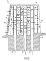
- the Figures 1 to 3 represent a moving blade 10 of a turbomachine, such as a moving blade of a high-pressure turbine.
- a turbomachine such as a moving blade of a high-pressure turbine.
- the invention can also be applied to other blades turbomachine, for example the blades of the low-pressure turbine thereof.
- the blade 10 comprises an aerodynamic surface (or blade) which extends radially between a blade root 12 and a blade tip 14.
- This aerodynamic surface consists of a leading edge 16 disposed opposite the blade. flow of the hot gases from the combustion chamber of the turbomachine, a trailing edge 18 opposite the leading edge 16, a lateral face 20 and an extrados lateral face 22, these lateral faces 20 , 22 connecting the leading edge 16 to the trailing edge 18.
- the moving blade 10 of a turbomachine comprises in its central part C , that is to say in its part for which the distance between its intrados 20 and extrados faces 22 is the most important, a cooling circuit with a lower pressure and an extrados cooling circuit.
- the intrados cooling circuit of the blade comprises in particular at least a first intrados cavity 24, a second intrados cavity 26 and a central cavity 28 (a larger number of intrados cavities is perfectly possible).
- the cavities 24, 26 and 28 extend radially between the foot 12 and the top 14 of the blade.
- the intrados cavities 24, 26 extend in the direction of the thickness of the blade (that is to say in the direction of its width defined between its faces intrados 20 and extrados 22) from the face intrados 20 of the blade to a wall (or partition) central 30 extending, firstly radially between the foot 12 and the top 14 of the blade, and secondly in the direction of the skeleton 32 of dawn.
- the central cavity 28 it extends in the direction of the thickness of the blade from its intrados face 20 to its extrados face 22.
- the intrados cooling circuit also comprises an air inlet opening 34 at a radial end of the first intrados cavity 24 (here at the foot 12 of the blade) to supply air to the intrados circuit.
- a first passage 36 communicates the other radial end of the first intrados cavity 24 (that is to say at the top 14 of the blade) with a radial end adjacent to the second cavity intrados 26.
- a second passage 38 does communicate the other radial end of the second intrados cavity 26 (that is to say at the root 12 of the blade) with a radial end adjacent to the central cavity 28 of the intrados circuit.
- the intrados cooling circuit also has outlet orifices 40 opening in the central cavity 28 and opening on the intrados face 20 of the blade. These orifices 40 are regularly distributed over the entire radial height of the blade.
- the circulation of the cooling air which runs through this intrados circuit follows clearly from the foregoing.
- the circuit is supplied with cooling air through the inlet opening 34.
- the air first passes through the first intrados cavity 24 and then the second intrados cavity 26 and finally the central cavity 28 before being emitted on the underside 20 of the dawn through the outlet ports 40.
- the extrados cooling circuit of the blade comprises in particular at least a first extrados cavity 42, a second extrados cavity 44 and a central cavity 46 (a larger number of extrados cavities is perfectly possible).
- the cavities 42, 44 and 46 extend radially between the foot 12 and the top 14 of the blade.
- the extrados cavities 42, 44 extend in the direction of the thickness of the blade from the extrados face 22 of the blade to the central wall 30 defined above in connection with the cooling system intrados of dawn.
- the central cavity 46 it extends in the direction of the thickness of the blade from its intrados face 20 to its extrados face 22.
- the extrados cooling circuit also comprises an air intake opening 48 at a radial end of the first extrados cavity 42 (here at the foot 12 of the blade) to supply air to the extrados circuit.
- a first passage 50 communicates the other radial end of the first extrados cavity 42 (that is to say at the top 14 of the blade) with a radial end adjacent to the second extrados cavity 44.
- a second passage 52 communicates the other radial end of the second extrados cavity 44 (that is to say at the root 12 of the blade) with a radial end adjacent to the central cavity 46 of the extrados circuit.
- the extrados cooling circuit also has outlet orifices 54 opening in the central cavity 46 and opening on the intrados face 20 of the blade. These orifices 54 are regularly distributed over the entire radial height of the blade.
- the circulation of the cooling air which runs through this extrados circuit derives evidently from the foregoing.
- the circuit is supplied with cooling air through the inlet opening 48.
- the air firstly travels through the first extrados cavity 42 and then the second extrados cavity 44 and finally the central cavity 46 before being emitted on the underside 20 of the dawn through the outlets 54.
- the inner and outer cooling circuits each have their own air inlet opening and that there is no air communication from one circuit to the other so that these circuits are completely independent of each other. one of the other.
- intrados cavities 24, 26 and the extrados cavities 42, 44 of the intrados and extrados cooling circuits are disposed on either side of the central wall 30.
- the central cavity 28 of the intrados circuit is located the side of the leading edge 16 of the blade, while the central cavity 46 of the extrados circuit is disposed on the side of the trailing edge 18 of the blade.
- the internal walls of the cavities 24, 26, 28, 42, 44 and 46 of the suction and extrados cooling circuits may advantageously be provided with flow interferers 56 intended to increase heat transfer along these walls.
- These flow disruptors may be in the form of ribs which are straight or inclined relative to the axis of rotation of the blade or in the form of pins or in any other equivalent form.
- Additional cooling circuits make it possible to cool the leading edge 16 and the trailing edge 18 of the blade.
- the leading edge cooling circuit comprises at least one cavity 58 extending radially in the vicinity of the leading edge 16 of the blade, at least one air inlet opening 60, 60 'opening in the leading edge cavity 58 and orifices of output 62 opening in the leading edge cavity and opening on the leading edge of the blade.
- the trailing edge cooling circuit comprises at least one cavity 64 extending radially in the vicinity of the trailing edge 18 of the blade, at least one air intake orifice 66, 66 'opening into the cavity trailing edge 64 and outlets 68 opening in the cavity trailing edge and opening on the underside face 20 of the blade.
- the leading edge cooling circuit comprises a central cavity 70 which extends radially between the root 12 and the top 14 of the blade and in the direction of the thickness of the blade from the lower surface 20 to the on the upper surface of dawn.
- An air intake opening 72 is provided at a radial end of this central cavity 70 (here at the foot 12 of the blade).
- the leading edge circuit also comprises a plurality of air intake orifices 60 distributed over the entire height of the blade. These orifices open into the central cavity 70 and open into the leading edge cavity 58.
- the cooling air travels through the central cavity 70 and the leading edge cavity 58 before being emitted to the leading edge 16 of the blade through the outlet orifices 62.
- the emission of air can also be performed on the underside 20 and on the extrados 22 of the dawn.
- the trailing edge cooling circuit further comprises a central cavity 74 extending radially and in the direction of the thickness of the blade from the lower surface 20 to the extrados 22 of the blade and an opening 76 at a radial end of the central cavity 74 (here at the foot 12 of the blade) for supplying air to the circuit.
- the circulation of air in this trailing edge cooling circuit is similar to that of the leading edge circuit: the air travels through the cavity central 74 and the cavity trailing edge 64 before being emitted on the underside face 20 of the blade at the trailing edge 18 of the latter.
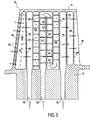
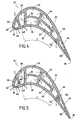
- the air intake port of the leading edge and trailing edge circuits of the blade 10 ' are openings at the respective radial end of the leading edge 58 and trailing edge 64 cavities (in FIG. the occurrence at the foot 12 of the dawn) and opening in the latter.
- These air intake ports are not shown on the figure 4 but they are of the same type as those feeding the cooling circuits intrados and extrados of the dawn.
- the cooling air therefore flows through the leading edge 58 and trailing edge 64 cavities of the foot 12 towards the apex 14 of the blade before being emitted by the respective outlet orifices 62, 68.
- the blade leading edge cooling circuit 10 "has a plurality of air intake ports 60 'opening into the leading edge cavity 58 and opening into the central cavity 28 of the cooling circuit. Inlet cooling.
- the blade trailing edge cooling circuit 10 "has a plurality of air intake orifices 66 'opening into the trailing edge cavity 64 and opening into the central cavity 46 of the cooling circuit. extrados cooling.
- the cooling air supplying the leading edge and trailing edge circuits respectively comes from the intrados and extrados circuits of the blade.
- the cooling circuits according to the invention have many advantages.
- the presence of a central wall that is located along the skeleton in the central part of the blade and which is cooled by the air flowing through the intrados and extrados cavities of the intrados and extrados circuits allows to ensure an efficient and homogeneous cooling of the blade. This results in a significant drop in the average temperature of the dawn which has the effect of significantly increasing the life of the dawn and thus delay their replacement.
- the aerodynamic performance of the turbine equipped with such blades are also not degraded by the presence of these cooling circuits.
- the manufacture by molding of a blade provided with such cooling circuits does not pose any particular problem.
- the cooling mode of the blades according to the invention also has the advantage of being able to easily adapt to so-called "high torque master” blades.
- the master-couple of a dawn corresponds to the most important area of a circle inscribed in the cup of a dawn. Also, a dawn with a strong master-torque has a larger diameter circle than a standard master-torque dawn.
Landscapes
- Engineering & Computer Science (AREA)
- Mechanical Engineering (AREA)
- General Engineering & Computer Science (AREA)
- Turbine Rotor Nozzle Sealing (AREA)
Applications Claiming Priority (1)
| Application Number | Priority Date | Filing Date | Title |
|---|---|---|---|
| FR0506266A FR2887287B1 (fr) | 2005-06-21 | 2005-06-21 | Circuits de refroidissement pour aube mobile de turbomachine |
Publications (2)
| Publication Number | Publication Date |
|---|---|
| EP1741875A1 EP1741875A1 (fr) | 2007-01-10 |
| EP1741875B1 true EP1741875B1 (fr) | 2008-09-17 |
Family
ID=35923394
Family Applications (1)
| Application Number | Title | Priority Date | Filing Date |
|---|---|---|---|
| EP06115023A Active EP1741875B1 (fr) | 2005-06-21 | 2006-06-06 | Circuits de refroidissement pour aube mobile de turbomachine |
Country Status (7)
| Country | Link |
|---|---|
| US (1) | US7513739B2 (enExample) |
| EP (1) | EP1741875B1 (enExample) |
| JP (1) | JP4801513B2 (enExample) |
| CA (1) | CA2550442C (enExample) |
| DE (1) | DE602006002782D1 (enExample) |
| FR (1) | FR2887287B1 (enExample) |
| RU (1) | RU2403402C2 (enExample) |
Families Citing this family (25)
| Publication number | Priority date | Publication date | Assignee | Title |
|---|---|---|---|---|
| FR2893974B1 (fr) * | 2005-11-28 | 2011-03-18 | Snecma | Circuit de refroidissement central pour aube mobile de turbomachine |
| US7296973B2 (en) * | 2005-12-05 | 2007-11-20 | General Electric Company | Parallel serpentine cooled blade |
| US7862299B1 (en) * | 2007-03-21 | 2011-01-04 | Florida Turbine Technologies, Inc. | Two piece hollow turbine blade with serpentine cooling circuits |
| US7985049B1 (en) * | 2007-07-20 | 2011-07-26 | Florida Turbine Technologies, Inc. | Turbine blade with impingement cooling |
| WO2009016744A1 (ja) * | 2007-07-31 | 2009-02-05 | Mitsubishi Heavy Industries, Ltd. | タービン用翼 |
| US10156143B2 (en) * | 2007-12-06 | 2018-12-18 | United Technologies Corporation | Gas turbine engines and related systems involving air-cooled vanes |
| US9995148B2 (en) * | 2012-10-04 | 2018-06-12 | General Electric Company | Method and apparatus for cooling gas turbine and rotor blades |
| JP5567180B1 (ja) * | 2013-05-20 | 2014-08-06 | 川崎重工業株式会社 | タービン翼の冷却構造 |
| US9803500B2 (en) * | 2014-05-05 | 2017-10-31 | United Technologies Corporation | Gas turbine engine airfoil cooling passage configuration |
| US10012090B2 (en) * | 2014-07-25 | 2018-07-03 | United Technologies Corporation | Airfoil cooling apparatus |
| WO2016022126A1 (en) * | 2014-08-07 | 2016-02-11 | Siemens Aktiengesellschaft | Turbine airfoil cooling system with bifurcated mid-chord cooling chamber |
| US11280214B2 (en) * | 2014-10-20 | 2022-03-22 | Raytheon Technologies Corporation | Gas turbine engine component |
| FR3032173B1 (fr) * | 2015-01-29 | 2018-07-27 | Safran Aircraft Engines | Pale d'helice de turbopropulseur a soufflage |
| FR3067390B1 (fr) | 2017-04-10 | 2019-11-29 | Safran | Aube de turbine presentant une structure amelioree |
| FR3067389B1 (fr) | 2017-04-10 | 2021-10-29 | Safran | Aube de turbine presentant une structure amelioree |
| US10626734B2 (en) | 2017-10-03 | 2020-04-21 | United Technologies Corporation | Airfoil having internal hybrid cooling cavities |
| US10626733B2 (en) | 2017-10-03 | 2020-04-21 | United Technologies Corporation | Airfoil having internal hybrid cooling cavities |
| US10704398B2 (en) * | 2017-10-03 | 2020-07-07 | Raytheon Technologies Corporation | Airfoil having internal hybrid cooling cavities |
| US10633980B2 (en) | 2017-10-03 | 2020-04-28 | United Technologies Coproration | Airfoil having internal hybrid cooling cavities |
| US10920597B2 (en) * | 2017-12-13 | 2021-02-16 | Solar Turbines Incorporated | Turbine blade cooling system with channel transition |
| FR3095834B1 (fr) * | 2019-05-09 | 2021-06-04 | Safran | Aube de turbomachine à refroidissement amélioré |
| US11732594B2 (en) | 2019-11-27 | 2023-08-22 | General Electric Company | Cooling assembly for a turbine assembly |
| FR3107920B1 (fr) | 2020-03-03 | 2023-11-10 | Safran Aircraft Engines | Aube creuse de turbomachine et plateforme inter-aubes équipées de saillies perturbatrices de flux de refroidissement |
| CN113090335A (zh) * | 2021-05-14 | 2021-07-09 | 中国航发湖南动力机械研究所 | 一种用于涡轮转子叶片的冲击加气膜双层壁冷却结构 |
| US12410717B2 (en) * | 2023-03-17 | 2025-09-09 | Doosan Enerbility Co., Ltd. | Gas turbine blade with cooling flow paths and gas turbine including the same |
Family Cites Families (19)
| Publication number | Priority date | Publication date | Assignee | Title |
|---|---|---|---|---|
| JPH06102963B2 (ja) * | 1983-12-22 | 1994-12-14 | 株式会社東芝 | ガスタ−ビン空冷翼 |
| JPH0233843B2 (ja) * | 1984-03-23 | 1990-07-31 | Kogyo Gijutsuin | Gasutaabindoyokunoreikyakukozo |
| SU1287678A2 (ru) * | 1984-09-11 | 1997-02-20 | О.С. Чернилевский | Охлаждаемая лопатка турбины |
| US5165852A (en) * | 1990-12-18 | 1992-11-24 | General Electric Company | Rotation enhanced rotor blade cooling using a double row of coolant passageways |
| FR2672338B1 (fr) * | 1991-02-06 | 1993-04-16 | Snecma | Aube de turbine munie d'un systeme de refroidissement. |
| US5813835A (en) * | 1991-08-19 | 1998-09-29 | The United States Of America As Represented By The Secretary Of The Air Force | Air-cooled turbine blade |
| US5356265A (en) * | 1992-08-25 | 1994-10-18 | General Electric Company | Chordally bifurcated turbine blade |
| US5387085A (en) * | 1994-01-07 | 1995-02-07 | General Electric Company | Turbine blade composite cooling circuit |
| SE512384C2 (sv) * | 1998-05-25 | 2000-03-06 | Abb Ab | Komponent för en gasturbin |
| US6126396A (en) * | 1998-12-09 | 2000-10-03 | General Electric Company | AFT flowing serpentine airfoil cooling circuit with side wall impingement cooling chambers |
| US6168381B1 (en) * | 1999-06-29 | 2001-01-02 | General Electric Company | Airfoil isolated leading edge cooling |
| FR2829175B1 (fr) * | 2001-08-28 | 2003-11-07 | Snecma Moteurs | Circuits de refroidissement pour aube de turbine a gaz |
| FR2829174B1 (fr) * | 2001-08-28 | 2006-01-20 | Snecma Moteurs | Perfectionnement apportes aux circuits de refroidissement pour aube de turbine a gaz |
| FR2833298B1 (fr) * | 2001-12-10 | 2004-08-06 | Snecma Moteurs | Perfectionnements apportes au comportement thermique du bord de fuite d'une aube de turbine haute-pression |
| US6607356B2 (en) * | 2002-01-11 | 2003-08-19 | General Electric Company | Crossover cooled airfoil trailing edge |
| EP1362982B1 (en) * | 2002-05-09 | 2010-08-18 | General Electric Company | Turbine airfoil with single aft flowing three pass serpentine cooling circuit |
| US7097426B2 (en) * | 2004-04-08 | 2006-08-29 | General Electric Company | Cascade impingement cooled airfoil |
| US7296972B2 (en) * | 2005-12-02 | 2007-11-20 | Siemens Power Generation, Inc. | Turbine airfoil with counter-flow serpentine channels |
| US7296973B2 (en) * | 2005-12-05 | 2007-11-20 | General Electric Company | Parallel serpentine cooled blade |
-
2005
- 2005-06-21 FR FR0506266A patent/FR2887287B1/fr not_active Expired - Fee Related
-
2006
- 2006-06-06 EP EP06115023A patent/EP1741875B1/fr active Active
- 2006-06-06 DE DE602006002782T patent/DE602006002782D1/de active Active
- 2006-06-15 US US11/452,971 patent/US7513739B2/en active Active
- 2006-06-15 JP JP2006165609A patent/JP4801513B2/ja active Active
- 2006-06-19 CA CA2550442A patent/CA2550442C/fr active Active
- 2006-06-20 RU RU2006122178/06A patent/RU2403402C2/ru active
Also Published As
| Publication number | Publication date |
|---|---|
| EP1741875A1 (fr) | 2007-01-10 |
| JP2007002843A (ja) | 2007-01-11 |
| CA2550442A1 (fr) | 2006-12-21 |
| CA2550442C (fr) | 2012-12-04 |
| US7513739B2 (en) | 2009-04-07 |
| DE602006002782D1 (de) | 2008-10-30 |
| FR2887287A1 (fr) | 2006-12-22 |
| JP4801513B2 (ja) | 2011-10-26 |
| FR2887287B1 (fr) | 2007-09-21 |
| US20070116570A1 (en) | 2007-05-24 |
| RU2006122178A (ru) | 2007-12-27 |
| RU2403402C2 (ru) | 2010-11-10 |
Similar Documents
| Publication | Publication Date | Title |
|---|---|---|
| EP1741875B1 (fr) | Circuits de refroidissement pour aube mobile de turbomachine | |
| EP0666406B1 (fr) | Aube fixe ou mobile refroidie de turbine | |
| EP1726783B1 (fr) | Aube creuse de rotor pour la turbine d'un moteur à turbine à gaz, équipée d'une baignoire | |
| EP1288438B1 (fr) | Circuits de refroidissement pour aube de turbine à gaz | |
| EP1288439B1 (fr) | Circuit de refroidissement pour aube de turbine à gaz | |
| EP2088286B1 (fr) | Aube, roue à aube et turbomachine associées | |
| CA2475083C (fr) | Circuits de refroidissement pour aube de turbine a gaz | |
| EP1790819B1 (fr) | Aube mobile de turbomachine comprenant un circuit de refroidissement | |
| EP3134620B1 (fr) | Aube pour turbine de turbomachine comprenant un circuit de refroidissement à homogénéité améliorée | |
| EP3519679B1 (fr) | Aube de turbine comportant un circuit de refroidissement | |
| EP1333155A1 (fr) | Aube mobile de turbine haute pression munie d'un bord de fuite refroidi | |
| EP4107369B1 (fr) | Aube de turbine comportant trois types d'orifices de refroidissement du bord de fuite | |
| CA2504168C (fr) | Circuit de refroidissement a cavite a rapport de forme eleve pour aube de turbine a gaz | |
| CA2569563C (fr) | Aube de turbine a refroidissement et a duree de vie ameliores | |
| WO2020193913A1 (fr) | Aube de turbomachine equipee d'un circuit de refroidissement optimise | |
| EP3610132B1 (fr) | Aube à circuit de refroidissement perfectionné | |
| FR3111661A1 (fr) | Aube de turbine avec système de refroidissement | |
| FR3085713A1 (fr) | Aube d'une turbine de turbomachine | |
| WO2018215718A1 (fr) | Aube pour turbine de turbomachine comprenant des cavites internes de circulation d'air de refroidissement |
Legal Events
| Date | Code | Title | Description |
|---|---|---|---|
| PUAI | Public reference made under article 153(3) epc to a published international application that has entered the european phase |
Free format text: ORIGINAL CODE: 0009012 |
|
| 17P | Request for examination filed |
Effective date: 20060606 |
|
| AK | Designated contracting states |
Kind code of ref document: A1 Designated state(s): AT BE BG CH CY CZ DE DK EE ES FI FR GB GR HU IE IS IT LI LT LU LV MC NL PL PT RO SE SI SK TR |
|
| AX | Request for extension of the european patent |
Extension state: AL BA HR MK YU |
|
| AKX | Designation fees paid |
Designated state(s): DE FR GB SE |
|
| GRAP | Despatch of communication of intention to grant a patent |
Free format text: ORIGINAL CODE: EPIDOSNIGR1 |
|
| GRAS | Grant fee paid |
Free format text: ORIGINAL CODE: EPIDOSNIGR3 |
|
| GRAA | (expected) grant |
Free format text: ORIGINAL CODE: 0009210 |
|
| AK | Designated contracting states |
Kind code of ref document: B1 Designated state(s): DE FR GB SE |
|
| REG | Reference to a national code |
Ref country code: GB Ref legal event code: FG4D Free format text: NOT ENGLISH |
|
| REF | Corresponds to: |
Ref document number: 602006002782 Country of ref document: DE Date of ref document: 20081030 Kind code of ref document: P |
|
| REG | Reference to a national code |
Ref country code: SE Ref legal event code: TRGR |
|
| PLBE | No opposition filed within time limit |
Free format text: ORIGINAL CODE: 0009261 |
|
| STAA | Information on the status of an ep patent application or granted ep patent |
Free format text: STATUS: NO OPPOSITION FILED WITHIN TIME LIMIT |
|
| 26N | No opposition filed |
Effective date: 20090618 |
|
| REG | Reference to a national code |
Ref country code: FR Ref legal event code: PLFP Year of fee payment: 11 |
|
| REG | Reference to a national code |
Ref country code: FR Ref legal event code: PLFP Year of fee payment: 12 |
|
| REG | Reference to a national code |
Ref country code: FR Ref legal event code: CD Owner name: SAFRAN AIRCRAFT ENGINES Effective date: 20170719 |
|
| REG | Reference to a national code |
Ref country code: FR Ref legal event code: PLFP Year of fee payment: 13 |
|
| REG | Reference to a national code |
Ref country code: DE Ref legal event code: R082 Ref document number: 602006002782 Country of ref document: DE Representative=s name: CBDL PATENTANWAELTE GBR, DE Ref country code: DE Ref legal event code: R082 Ref document number: 602006002782 Country of ref document: DE Representative=s name: CBDL PATENTANWAELTE EGBR, DE |
|
| PGFP | Annual fee paid to national office [announced via postgrant information from national office to epo] |
Ref country code: DE Payment date: 20250618 Year of fee payment: 20 |
|
| PGFP | Annual fee paid to national office [announced via postgrant information from national office to epo] |
Ref country code: GB Payment date: 20250625 Year of fee payment: 20 |
|
| PGFP | Annual fee paid to national office [announced via postgrant information from national office to epo] |
Ref country code: FR Payment date: 20250620 Year of fee payment: 20 |
|
| PGFP | Annual fee paid to national office [announced via postgrant information from national office to epo] |
Ref country code: SE Payment date: 20250618 Year of fee payment: 20 |