EP1741875B1 - Cooling circuit for a rotor blade of a turbomachine - Google Patents
Cooling circuit for a rotor blade of a turbomachine Download PDFInfo
- Publication number
- EP1741875B1 EP1741875B1 EP06115023A EP06115023A EP1741875B1 EP 1741875 B1 EP1741875 B1 EP 1741875B1 EP 06115023 A EP06115023 A EP 06115023A EP 06115023 A EP06115023 A EP 06115023A EP 1741875 B1 EP1741875 B1 EP 1741875B1
- Authority
- EP
- European Patent Office
- Prior art keywords
- blade
- cavity
- pressure
- radial end
- suction
- Prior art date
- Legal status (The legal status is an assumption and is not a legal conclusion. Google has not performed a legal analysis and makes no representation as to the accuracy of the status listed.)
- Active
Links
Images

Classifications
-
- F—MECHANICAL ENGINEERING; LIGHTING; HEATING; WEAPONS; BLASTING
- F01—MACHINES OR ENGINES IN GENERAL; ENGINE PLANTS IN GENERAL; STEAM ENGINES
- F01D—NON-POSITIVE DISPLACEMENT MACHINES OR ENGINES, e.g. STEAM TURBINES
- F01D5/00—Blades; Blade-carrying members; Heating, heat-insulating, cooling or antivibration means on the blades or the members
- F01D5/12—Blades
- F01D5/14—Form or construction
- F01D5/18—Hollow blades, i.e. blades with cooling or heating channels or cavities; Heating, heat-insulating or cooling means on blades
- F01D5/187—Convection cooling
-
- F—MECHANICAL ENGINEERING; LIGHTING; HEATING; WEAPONS; BLASTING
- F05—INDEXING SCHEMES RELATING TO ENGINES OR PUMPS IN VARIOUS SUBCLASSES OF CLASSES F01-F04
- F05D—INDEXING SCHEME FOR ASPECTS RELATING TO NON-POSITIVE-DISPLACEMENT MACHINES OR ENGINES, GAS-TURBINES OR JET-PROPULSION PLANTS
- F05D2260/00—Function
- F05D2260/20—Heat transfer, e.g. cooling
- F05D2260/202—Heat transfer, e.g. cooling by film cooling
Definitions
- the present invention relates to the general field of cooling turbomachine moving blades, and in particular to the blades of the high-pressure turbine.
- the main purpose of the present invention is therefore to overcome such drawbacks by proposing a cooling circuit for a mobile blade that allows efficient cooling of the blade without degrading the blades. aerodynamic performance of the turbine and which has a low manufacturing cost.
- the blade according to the invention comprises in its central part a lower pressure cooling circuit and an extrados cooling circuit.
- the intrados cooling circuit comprises at least first and second intrados cavities extending radially and in the direction of the thickness of the blade from the intrados of the blade to a radially extending central wall and in the direction of the skeleton of the dawn, a central cavity extending radially and in the direction of the thickness of the blade from the intrados to the extrados of the dawn, an opening of air at a radial end of the first intrados cavity to supply air to the intrados circuit, a first passage communicating the other radial end of the first intrados cavity with a radial end adjacent to the second intrados cavity, a second passage communicating the other radial end of the second intrados cavity with a radial end adjacent to the central cavity, and outlet orifices opening into the central cavity and opening on the intrados face of the dawn .
- the extrados cooling circuit comprises at least a first and a second extrados cavity extending radially and in the direction of the thickness of the blade from the extrados of the blade to the central wall, a central cavity extending radially and in the direction of the thickness of the blade from the intrados to the extrados of the blade, an air inlet opening at a radial end of the first cavity extrados for supplying air to the extrados circuit, a first passage communicating the other radial end of the first extrados cavity with a radial end adjacent to the second extrados cavity, a second passage communicating the other radial end of the second extrados cavity with a radial end close to the central cavity, and outlet orifices opening into the central cavity and opening on the intrados face of the blade.
- the blade further comprises a cooling circuit leading edge comprising at least one cavity extending radially in the vicinity of the leading edge of the blade, at least one orifice of air inlet opening into the leading edge cavity and outlet openings opening into said leading edge cavity and opening on the leading edge of the blade.
- the blade further comprises a trailing edge cooling circuit comprising at least one cavity extending radially in the vicinity of the trailing edge of the blade, at least one inlet orifice. air opening into the cavity trailing edge and outlet openings opening in said cavity trailing edge and opening on the intrados face of the blade.
- the internal walls of the cavities of the intrados and extrados cooling circuits are provided with flow interferers intended to increase the heat transfer along these walls.
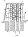
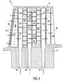
- the Figures 1 to 3 represent a moving blade 10 of a turbomachine, such as a moving blade of a high-pressure turbine.
- a turbomachine such as a moving blade of a high-pressure turbine.
- the invention can also be applied to other blades turbomachine, for example the blades of the low-pressure turbine thereof.
- the blade 10 comprises an aerodynamic surface (or blade) which extends radially between a blade root 12 and a blade tip 14.
- This aerodynamic surface consists of a leading edge 16 disposed opposite the blade. flow of the hot gases from the combustion chamber of the turbomachine, a trailing edge 18 opposite the leading edge 16, a lateral face 20 and an extrados lateral face 22, these lateral faces 20 , 22 connecting the leading edge 16 to the trailing edge 18.
- the moving blade 10 of a turbomachine comprises in its central part C , that is to say in its part for which the distance between its intrados 20 and extrados faces 22 is the most important, a cooling circuit with a lower pressure and an extrados cooling circuit.
- the intrados cooling circuit of the blade comprises in particular at least a first intrados cavity 24, a second intrados cavity 26 and a central cavity 28 (a larger number of intrados cavities is perfectly possible).
- the cavities 24, 26 and 28 extend radially between the foot 12 and the top 14 of the blade.
- the intrados cavities 24, 26 extend in the direction of the thickness of the blade (that is to say in the direction of its width defined between its faces intrados 20 and extrados 22) from the face intrados 20 of the blade to a wall (or partition) central 30 extending, firstly radially between the foot 12 and the top 14 of the blade, and secondly in the direction of the skeleton 32 of dawn.
- the central cavity 28 it extends in the direction of the thickness of the blade from its intrados face 20 to its extrados face 22.
- the intrados cooling circuit also comprises an air inlet opening 34 at a radial end of the first intrados cavity 24 (here at the foot 12 of the blade) to supply air to the intrados circuit.
- a first passage 36 communicates the other radial end of the first intrados cavity 24 (that is to say at the top 14 of the blade) with a radial end adjacent to the second cavity intrados 26.
- a second passage 38 does communicate the other radial end of the second intrados cavity 26 (that is to say at the root 12 of the blade) with a radial end adjacent to the central cavity 28 of the intrados circuit.
- the intrados cooling circuit also has outlet orifices 40 opening in the central cavity 28 and opening on the intrados face 20 of the blade. These orifices 40 are regularly distributed over the entire radial height of the blade.
- the circulation of the cooling air which runs through this intrados circuit follows clearly from the foregoing.
- the circuit is supplied with cooling air through the inlet opening 34.
- the air first passes through the first intrados cavity 24 and then the second intrados cavity 26 and finally the central cavity 28 before being emitted on the underside 20 of the dawn through the outlet ports 40.
- the extrados cooling circuit of the blade comprises in particular at least a first extrados cavity 42, a second extrados cavity 44 and a central cavity 46 (a larger number of extrados cavities is perfectly possible).
- the cavities 42, 44 and 46 extend radially between the foot 12 and the top 14 of the blade.
- the extrados cavities 42, 44 extend in the direction of the thickness of the blade from the extrados face 22 of the blade to the central wall 30 defined above in connection with the cooling system intrados of dawn.
- the central cavity 46 it extends in the direction of the thickness of the blade from its intrados face 20 to its extrados face 22.
- the extrados cooling circuit also comprises an air intake opening 48 at a radial end of the first extrados cavity 42 (here at the foot 12 of the blade) to supply air to the extrados circuit.
- a first passage 50 communicates the other radial end of the first extrados cavity 42 (that is to say at the top 14 of the blade) with a radial end adjacent to the second extrados cavity 44.
- a second passage 52 communicates the other radial end of the second extrados cavity 44 (that is to say at the root 12 of the blade) with a radial end adjacent to the central cavity 46 of the extrados circuit.
- the extrados cooling circuit also has outlet orifices 54 opening in the central cavity 46 and opening on the intrados face 20 of the blade. These orifices 54 are regularly distributed over the entire radial height of the blade.
- the circulation of the cooling air which runs through this extrados circuit derives evidently from the foregoing.
- the circuit is supplied with cooling air through the inlet opening 48.
- the air firstly travels through the first extrados cavity 42 and then the second extrados cavity 44 and finally the central cavity 46 before being emitted on the underside 20 of the dawn through the outlets 54.
- the inner and outer cooling circuits each have their own air inlet opening and that there is no air communication from one circuit to the other so that these circuits are completely independent of each other. one of the other.
- intrados cavities 24, 26 and the extrados cavities 42, 44 of the intrados and extrados cooling circuits are disposed on either side of the central wall 30.
- the central cavity 28 of the intrados circuit is located the side of the leading edge 16 of the blade, while the central cavity 46 of the extrados circuit is disposed on the side of the trailing edge 18 of the blade.
- the internal walls of the cavities 24, 26, 28, 42, 44 and 46 of the suction and extrados cooling circuits may advantageously be provided with flow interferers 56 intended to increase heat transfer along these walls.
- These flow disruptors may be in the form of ribs which are straight or inclined relative to the axis of rotation of the blade or in the form of pins or in any other equivalent form.
- Additional cooling circuits make it possible to cool the leading edge 16 and the trailing edge 18 of the blade.
- the leading edge cooling circuit comprises at least one cavity 58 extending radially in the vicinity of the leading edge 16 of the blade, at least one air inlet opening 60, 60 'opening in the leading edge cavity 58 and orifices of output 62 opening in the leading edge cavity and opening on the leading edge of the blade.
- the trailing edge cooling circuit comprises at least one cavity 64 extending radially in the vicinity of the trailing edge 18 of the blade, at least one air intake orifice 66, 66 'opening into the cavity trailing edge 64 and outlets 68 opening in the cavity trailing edge and opening on the underside face 20 of the blade.
- the leading edge cooling circuit comprises a central cavity 70 which extends radially between the root 12 and the top 14 of the blade and in the direction of the thickness of the blade from the lower surface 20 to the on the upper surface of dawn.
- An air intake opening 72 is provided at a radial end of this central cavity 70 (here at the foot 12 of the blade).
- the leading edge circuit also comprises a plurality of air intake orifices 60 distributed over the entire height of the blade. These orifices open into the central cavity 70 and open into the leading edge cavity 58.
- the cooling air travels through the central cavity 70 and the leading edge cavity 58 before being emitted to the leading edge 16 of the blade through the outlet orifices 62.
- the emission of air can also be performed on the underside 20 and on the extrados 22 of the dawn.
- the trailing edge cooling circuit further comprises a central cavity 74 extending radially and in the direction of the thickness of the blade from the lower surface 20 to the extrados 22 of the blade and an opening 76 at a radial end of the central cavity 74 (here at the foot 12 of the blade) for supplying air to the circuit.
- the circulation of air in this trailing edge cooling circuit is similar to that of the leading edge circuit: the air travels through the cavity central 74 and the cavity trailing edge 64 before being emitted on the underside face 20 of the blade at the trailing edge 18 of the latter.
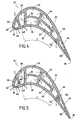
- the air intake port of the leading edge and trailing edge circuits of the blade 10 ' are openings at the respective radial end of the leading edge 58 and trailing edge 64 cavities (in FIG. the occurrence at the foot 12 of the dawn) and opening in the latter.
- These air intake ports are not shown on the figure 4 but they are of the same type as those feeding the cooling circuits intrados and extrados of the dawn.
- the cooling air therefore flows through the leading edge 58 and trailing edge 64 cavities of the foot 12 towards the apex 14 of the blade before being emitted by the respective outlet orifices 62, 68.
- the blade leading edge cooling circuit 10 "has a plurality of air intake ports 60 'opening into the leading edge cavity 58 and opening into the central cavity 28 of the cooling circuit. Inlet cooling.
- the blade trailing edge cooling circuit 10 "has a plurality of air intake orifices 66 'opening into the trailing edge cavity 64 and opening into the central cavity 46 of the cooling circuit. extrados cooling.
- the cooling air supplying the leading edge and trailing edge circuits respectively comes from the intrados and extrados circuits of the blade.
- the cooling circuits according to the invention have many advantages.
- the presence of a central wall that is located along the skeleton in the central part of the blade and which is cooled by the air flowing through the intrados and extrados cavities of the intrados and extrados circuits allows to ensure an efficient and homogeneous cooling of the blade. This results in a significant drop in the average temperature of the dawn which has the effect of significantly increasing the life of the dawn and thus delay their replacement.
- the aerodynamic performance of the turbine equipped with such blades are also not degraded by the presence of these cooling circuits.
- the manufacture by molding of a blade provided with such cooling circuits does not pose any particular problem.
- the cooling mode of the blades according to the invention also has the advantage of being able to easily adapt to so-called "high torque master” blades.
- the master-couple of a dawn corresponds to the most important area of a circle inscribed in the cup of a dawn. Also, a dawn with a strong master-torque has a larger diameter circle than a standard master-torque dawn.
Description
La présente invention se rapporte au domaine général du refroidissement des aubes mobiles de turbomachine, et notamment aux aubes de la turbine haute-pression.The present invention relates to the general field of cooling turbomachine moving blades, and in particular to the blades of the high-pressure turbine.
Il est connu de munir les aubes mobiles d'une turbine à gaz de turbomachine, telles que les turbines haute et basse pression, de circuits internes de refroidissement leur permettant de supporter sans dommages les températures très élevées auxquelles elles sont soumises pendant le fonctionnement de la turbomachine. Ainsi, dans le cas d'une turbine haute-pression, les températures des gaz issus de la chambre de combustion atteignent des valeurs largement supérieures à celles que peuvent supporter sans dommages les aubes mobiles de la turbine, ce qui a pour conséquence de limiter leur durée de vie.It is known to provide the blades of a turbomachine gas turbine, such as high and low pressure turbines, internal cooling circuits allowing them to withstand without damage the very high temperatures to which they are subjected during operation of the turbine engine. Thus, in the case of a high-pressure turbine, the temperatures of the gases from the combustion chamber reach values much higher than those which can withstand without damage the blades of the turbine, which has the consequence of limiting their lifetime.
Grâce à de tels circuits de refroidissement, de l'air, qui est généralement introduit dans l'aube par son pied, traverse celle-ci en suivant un trajet formé par des cavités pratiquées dans l'aube avant d'être éjecté par des orifices s'ouvrant à la surface de l'aube.By means of such cooling circuits, air, which is generally introduced into the blade by its foot, traverses the latter along a path formed by cavities formed in the blade before being ejected by orifices. opening on the surface of dawn.
Il existe de nombreuses réalisations différentes de ces circuits de refroidissement. Ainsi, certains circuits utilisent des cavités de refroidissement qui occupent toute la largeur de l'aube, ce qui présente l'inconvénient de limiter l'efficacité thermique du refroidissement. Dans le but de pallier ce défaut, d'autres circuits, tels que ceux décrits dans les documents
La présente invention a donc pour but principal de pallier de tels inconvénients en proposant un circuit de refroidissement pour aube mobile permettant un refroidissement efficace de l'aube sans dégrader les performances aérodynamiques de la turbine et qui présente un faible coût de fabrication.The main purpose of the present invention is therefore to overcome such drawbacks by proposing a cooling circuit for a mobile blade that allows efficient cooling of the blade without degrading the blades. aerodynamic performance of the turbine and which has a low manufacturing cost.
A cet effet, l'aube selon l'invention comporte dans sa partie centrale un circuit de refroidissement intrados et un circuit de refroidissement extrados. Le circuit de refroidissement intrados comprend au moins une première et une seconde cavités intrados s'étendant radialement et dans le sens de l'épaisseur de l'aube depuis l'intrados de l'aube jusqu'à une paroi centrale s'étendant radialement et selon la direction du squelette de l'aube, une cavité centrale s'étendant radialement et dans le sens de l'épaisseur de l'aube depuis l'intrados jusqu'à l'extrados de l'aube, une ouverture d'admission d'air à une extrémité radiale de la première cavité intrados pour alimenter en air le circuit intrados, un premier passage faisant communiquer l'autre extrémité radiale de la première cavité intrados avec une extrémité radiale voisine de la seconde cavité intrados, un second passage faisant communiquer l'autre extrémité radiale de la seconde cavité intrados avec une extrémité radiale voisine de la cavité centrale, et des orifices de sortie s'ouvrant dans la cavité centrale et débouchant sur la face intrados de l'aube. Quant au circuit de refroidissement extrados, il comprend au moins une première et une seconde cavités extrados s'étendant radialement et dans le sens de l'épaisseur de l'aube depuis l'extrados de l'aube jusqu'à la paroi centrale, une cavité centrale s'étendant radialement et dans le sens de l'épaisseur de l'aube depuis l'intrados jusqu'à l'extrados de l'aube, une ouverture d'admission d'air à une extrémité radiale de la première cavité extrados pour alimenter en air le circuit extrados, un premier passage faisant communiquer l'autre extrémité radiale de la première cavité extrados avec une extrémité radiale voisine de la seconde cavité extrados, un second passage faisant communiquer l'autre extrémité radiale de la seconde cavité extrados avec une extrémité radiale voisine de la cavité centrale, et des orifices de sortie s'ouvrant dans la cavité centrale et débouchant sur la face intrados de l'aube.For this purpose, the blade according to the invention comprises in its central part a lower pressure cooling circuit and an extrados cooling circuit. The intrados cooling circuit comprises at least first and second intrados cavities extending radially and in the direction of the thickness of the blade from the intrados of the blade to a radially extending central wall and in the direction of the skeleton of the dawn, a central cavity extending radially and in the direction of the thickness of the blade from the intrados to the extrados of the dawn, an opening of air at a radial end of the first intrados cavity to supply air to the intrados circuit, a first passage communicating the other radial end of the first intrados cavity with a radial end adjacent to the second intrados cavity, a second passage communicating the other radial end of the second intrados cavity with a radial end adjacent to the central cavity, and outlet orifices opening into the central cavity and opening on the intrados face of the dawn . As for the extrados cooling circuit, it comprises at least a first and a second extrados cavity extending radially and in the direction of the thickness of the blade from the extrados of the blade to the central wall, a central cavity extending radially and in the direction of the thickness of the blade from the intrados to the extrados of the blade, an air inlet opening at a radial end of the first cavity extrados for supplying air to the extrados circuit, a first passage communicating the other radial end of the first extrados cavity with a radial end adjacent to the second extrados cavity, a second passage communicating the other radial end of the second extrados cavity with a radial end close to the central cavity, and outlet orifices opening into the central cavity and opening on the intrados face of the blade.
Grâce à de tels circuits, il est possible d'obtenir un refroidissement homogène et efficace de l'aube. En effet, la paroi centrale séparant les cavités intrados des cavités extrados est refroidie par l'air circulant dans les circuits intrados et extrados. Il en résulte une chute de la température moyenne de l'aube ce qui a pour conséquence directe d'augmenter la durée de vie de l'aube. Par ailleurs, ces circuits de refroidissement ne posent aucun problème particulier de fabrication et d'implantation dans la turbine.Thanks to such circuits, it is possible to obtain a homogeneous and efficient cooling of the blade. In fact, the central wall separating the intrados cavities from the extrados cavities is cooled by the air circulating in the intrados and extrados circuits. This results in a fall in the average temperature of the dawn which has the direct consequence to increase the life of dawn. Moreover, these cooling circuits do not pose any particular problem of manufacture and implantation in the turbine.
Selon une disposition avantageuse de l'invention, l'aube comporte en outre un circuit de refroidissement bord d'attaque comprenant au moins une cavité s'étendant radialement au voisinage du bord d'attaque de l'aube, au moins un orifice d'admission d'air débouchant dans la cavité bord d'attaque et des orifices de sortie s'ouvrant dans ladite cavité bord d'attaque et débouchant sur le bord d'attaque de l'aube.According to an advantageous arrangement of the invention, the blade further comprises a cooling circuit leading edge comprising at least one cavity extending radially in the vicinity of the leading edge of the blade, at least one orifice of air inlet opening into the leading edge cavity and outlet openings opening into said leading edge cavity and opening on the leading edge of the blade.
Selon une autre disposition avantageuse de l'invention, l'aube comporte en outre un circuit de refroidissement bord de fuite comprenant au moins une cavité s'étendant radialement au voisinage du bord de fuite de l'aube, au moins un orifice d'admission d'air débouchant dans la cavité bord de fuite et des orifices de sortie s'ouvrant dans ladite cavité bord de fuite et débouchant sur la face intrados de l'aube.According to another advantageous arrangement of the invention, the blade further comprises a trailing edge cooling circuit comprising at least one cavity extending radially in the vicinity of the trailing edge of the blade, at least one inlet orifice. air opening into the cavity trailing edge and outlet openings opening in said cavity trailing edge and opening on the intrados face of the blade.
De préférence, les parois internes des cavités des circuits de refroidissement intrados et extrados sont munies de perturbateurs d'écoulement destinés à accroître les transferts thermiques le long de ces parois.Preferably, the internal walls of the cavities of the intrados and extrados cooling circuits are provided with flow interferers intended to increase the heat transfer along these walls.
D'autres caractéristiques et avantages de la présente invention ressortiront de la description faite ci-dessous, en référence aux dessins annexés qui en illustrent un exemple de réalisation dépourvu de tout caractère limitatif. Sur les figures :
- la
figure 1 est une vue en coupe transversale d'une aube mobile selon un mode de réalisation de l'invention; - les
figures 2 et3 sont des vues en coupe de lafigure 1 respectivement selon II-II et III-III ; et - les
figures 4 et 5 sont des vues en coupe transversale d'aubes mobiles selon d'autres modes de réalisation de l'invention.
- the
figure 1 is a cross-sectional view of a blade according to one embodiment of the invention; - the
figures 2 and3 are sectional views of thefigure 1 respectively according to II-II and III-III; and - the
Figures 4 and 5 are cross-sectional views of blades according to other embodiments of the invention.
Les
L'aube 10 comporte une surface aérodynamique (ou pale) qui s'étend radialement entre un pied d'aube 12 et un sommet d'aube 14. Cette surface aérodynamique se compose d'un bord d'attaque 16 disposé en regard de l'écoulement des gaz chauds issus de la chambre de combustion de la turbomachine, d'un bord de fuite 18 opposé au bord d'attaque 16, d'une face latérale intrados 20 et d'une face latérale extrados 22, ces faces latérales 20, 22 reliant le bord d'attaque 16 au bord de fuite 18.The
L'aube mobile 10 de turbomachine selon l'invention comporte dans sa partie centrale C, c'est-à-dire dans sa partie pour laquelle la distance entre ses faces intrados 20 et extrados 22 est la plus importante, un circuit de refroidissement intrados et un circuit de refroidissement extrados.The moving
Le circuit de refroidissement intrados de l'aube comporte notamment au moins une première cavité intrados 24, une seconde cavité intrados 26 et une cavité centrale 28 (un nombre plus important de cavités intrados est parfaitement envisageable). Les cavités 24, 26 et 28 s'étendent radialement entre le pied 12 et le sommet 14 de l'aube.The intrados cooling circuit of the blade comprises in particular at least a
Par ailleurs, les cavités intrados 24, 26 s'étendent dans le sens de l'épaisseur de l'aube (c'est-à-dire dans le sens de sa largeur définie entre ses faces intrados 20 et extrados 22) depuis la face intrados 20 de l'aube jusqu'à une paroi (ou cloison) centrale 30 s'étendant, d'une part radialement entre le pied 12 et le sommet 14 de l'aube, et d'autre part selon la direction du squelette 32 de l'aube. Quant à la cavité centrale 28, elle s'étend dans le sens de l'épaisseur de l'aube depuis sa face intrados 20 jusqu'à sa face extrados 22.On the other hand, the
En liaison avec la
Un premier passage 36 fait communiquer l'autre extrémité radiale de la première cavité intrados 24 (c'est-à-dire au niveau du sommet 14 de l'aube) avec une extrémité radiale voisine de la seconde cavité intrados 26. Un second passage 38 fait communiquer l'autre extrémité radiale de la seconde cavité intrados 26 (c'est-à-dire au niveau du pied 12 de l'aube) avec une extrémité radiale voisine de la cavité centrale 28 du circuit intrados.A
Le circuit de refroidissement intrados comporte aussi des orifices de sortie 40 s'ouvrant dans la cavité centrale 28 et débouchant sur la face intrados 20 de l'aube. Ces orifices 40 sont régulièrement répartis sur toute la hauteur radiale de l'aube.The intrados cooling circuit also has
La circulation de l'air de refroidissement qui parcourt ce circuit intrados découle de manière évidente de ce qui précède. Le circuit est alimenté en air de refroidissement par l'ouverture d'admission 34. L'air parcourt d'abord la première cavité intrados 24 puis la seconde cavité intrados 26 et enfin la cavité centrale 28 avant d'être émis à l'intrados 20 de l'aube par les orifices de sortie 40.The circulation of the cooling air which runs through this intrados circuit follows clearly from the foregoing. The circuit is supplied with cooling air through the inlet opening 34. The air first passes through the
Le circuit de refroidissement extrados de l'aube comporte notamment au moins une première cavité extrados 42, une seconde cavité extrados 44 et une cavité centrale 46 (un nombre plus important de cavités extrados est parfaitement envisageable). Les cavités 42, 44 et 46 s'étendent radialement entre le pied 12 et le sommet 14 de l'aube.The extrados cooling circuit of the blade comprises in particular at least a
De plus, les cavités extrados 42, 44 s'étendent dans le sens de l'épaisseur de l'aube depuis la face extrados 22 de l'aube jusqu'à la paroi centrale 30 définie précédemment en liaison avec le circuit de refroidissement intrados de l'aube. Quant à la cavité centrale 46, elle s'étend dans le sens de l'épaisseur de l'aube depuis sa face intrados 20 jusqu'à sa face extrados 22.In addition, the
Comme représenté sur la
Un premier passage 50 fait communiquer l'autre extrémité radiale de la première cavité extrados 42 (c'est-à-dire au niveau du sommet 14 de l'aube) avec une extrémité radiale voisine de la seconde cavité extrados 44. Un second passage 52 fait communiquer l'autre extrémité radiale de la seconde cavité extrados 44 (c'est-à-dire au niveau du pied 12 de l'aube) avec une extrémité radiale voisine de la cavité centrale 46 du circuit extrados.A
Le circuit de refroidissement extrados comporte aussi des orifices de sortie 54 s'ouvrant dans la cavité centrale 46 et débouchant sur la face intrados 20 de l'aube. Ces orifices 54 sont régulièrement répartis sur toute la hauteur radiale de l'aube.The extrados cooling circuit also has
La circulation de l'air de refroidissement qui parcourt ce circuit extrados découle de manière évidente de ce qui précède. Le circuit est alimenté en air de refroidissement par l'ouverture d'admission 48. L'air parcourt d'abord la première cavité extrados 42 puis la seconde cavité extrados 44 et enfin la cavité centrale 46 avant d'être émis à l'intrados 20 de l'aube par les orifices de sortie 54.The circulation of the cooling air which runs through this extrados circuit derives evidently from the foregoing. The circuit is supplied with cooling air through the inlet opening 48. The air firstly travels through the
On notera que les circuits de refroidissement intrados et extrados présentent chacun leur propre ouverture d'admission d'air et qu'il n'existe aucune communication d'air d'un circuit vers l'autre de sorte que ces circuits sont complètement indépendants l'un de l'autre.It will be noted that the inner and outer cooling circuits each have their own air inlet opening and that there is no air communication from one circuit to the other so that these circuits are completely independent of each other. one of the other.
On notera également que les cavités intrados 24, 26 et les cavités extrados 42, 44 des circuits de refroidissement intrados et extrados sont disposées de part et d'autre de la paroi centrale 30. De plus, la cavité centrale 28 du circuit intrados est située du côté du bord d'attaque 16 de l'aube, tandis que la cavité centrale 46 du circuit extrados est disposée du côté du bord de fuite 18 de l'aube.It will also be noted that the
Comme représenté sur les
Ces perturbateurs d'écoulement peuvent se présenter sous la forme de nervures qui sont droites ou inclinées par rapport à l'axe de rotation de l'aube ou sous la forme de picots ou encore sous toutes autres formes équivalentes.These flow disruptors may be in the form of ribs which are straight or inclined relative to the axis of rotation of the blade or in the form of pins or in any other equivalent form.
Des circuits de refroidissement supplémentaires permettent d'assurer le refroidissement du bord d'attaque 16 et du bord de fuite 18 de l'aube.Additional cooling circuits make it possible to cool the
De manière générale, le circuit de refroidissement bord d'attaque comprend au moins une cavité 58 s'étendant radialement au voisinage du bord d'attaque 16 de l'aube, au moins un orifice d'admission d'air 60, 60' débouchant dans la cavité bord d'attaque 58 et des orifices de sortie 62 s'ouvrant dans la cavité bord d'attaque et débouchant sur le bord d'attaque de l'aube.In general, the leading edge cooling circuit comprises at least one
Quant au circuit de refroidissement bord de fuite, il comprend au moins une cavité 64 s'étendant radialement au voisinage du bord de fuite 18 de l'aube, au moins un orifice d'admission d'air 66, 66' débouchant dans la cavité bord de fuite 64 et des orifices de sortie 68 s'ouvrant dans la cavité bord de fuite et débouchant sur la face intrados 20 de l'aube.As for the trailing edge cooling circuit, it comprises at least one
On décrira maintenant différentes variantes de réalisation de ces circuits de refroidissement supplémentaires.Various alternative embodiments of these additional cooling circuits will now be described.
Dans le mode de réalisation des
Le circuit bord d'attaque comporte également une pluralité d'orifices d'admission d'air 60 répartis sur toute la hauteur de l'aube. Ces orifices s'ouvrent dans la cavité centrale 70 et débouchent dans la cavité bord d'attaque 58.The leading edge circuit also comprises a plurality of
Ainsi, l'air de refroidissement parcourt la cavité centrale 70 puis la cavité bord d'attaque 58 avant d'être émis au bord d'attaque 16 de l'aube par les orifices de sortie 62. Comme représenté sur la
Toujours dans le mode de réalisation des
Une pluralité d'orifices d'admission d'air 66 répartis sur toute la hauteur de l'aube s'ouvrent dans la cavité centrale 74 de ce circuit et débouchent dans la cavité bord de fuite 64.A plurality of
La circulation de l'air dans ce circuit de refroidissement bord de fuite est similaire à celle du circuit bord d'attaque : l'air parcourt la cavité centrale 74 puis la cavité bord de fuite 64 avant d'être émis sur la face intrados 20 de l'aube au niveau du bord de fuite 18 de cette dernière.The circulation of air in this trailing edge cooling circuit is similar to that of the leading edge circuit: the air travels through the cavity central 74 and the
Selon un autre mode de réalisation représenté par la
L'air de refroidissement parcourt donc les cavités bord d'attaque 58 et bord de fuite 64 du pied 12 vers le sommet 14 de l'aube avant d'être émis par les orifices de sortie respectifs 62, 68.The cooling air therefore flows through the leading
Selon encore un autre mode de réalisation représenté par la
De même, le circuit de refroidissement bord de fuite de l'aube 10" comporte une pluralité d'orifices d'admission d'air 66' débouchant dans la cavité bord de fuite 64 et s'ouvrant dans la cavité centrale 46 du circuit de refroidissement extrados.Likewise, the blade trailing
Ainsi, l'air de refroidissement alimentant les circuits bord d'attaque et bord de fuite provient respectivement du circuit intrados et du circuit extrados de l'aube.Thus, the cooling air supplying the leading edge and trailing edge circuits respectively comes from the intrados and extrados circuits of the blade.
On notera que par rapport au mode de réalisation des
Par rapport au mode de réalisation de la
Les circuits de refroidissement selon l'invention présentent de nombreux avantages. En particulier, la présence d'une paroi centrale qui est située le long du squelette dans la partie centrale de l'aube et qui est refroidie par l'air parcourant les cavités intrados et extrados des circuits intrados et extrados permet d'assurer un refroidissement efficace et homogène de l'aube. Il en résulte une baisse importante de la température moyenne de l'aube ce qui a pour conséquence d'augmenter considérablement la durée de vie de l'aube et donc de retarder leur remplacement. Les performances aérodynamiques de la turbine équipée de telles aubes ne sont par ailleurs pas dégradées par la présence de ces circuits de refroidissement. La fabrication par moulage d'une aube munie de tels circuits de refroidissement ne pose en outre aucun problème particulier.The cooling circuits according to the invention have many advantages. In particular, the presence of a central wall that is located along the skeleton in the central part of the blade and which is cooled by the air flowing through the intrados and extrados cavities of the intrados and extrados circuits allows to ensure an efficient and homogeneous cooling of the blade. This results in a significant drop in the average temperature of the dawn which has the effect of significantly increasing the life of the dawn and thus delay their replacement. The aerodynamic performance of the turbine equipped with such blades are also not degraded by the presence of these cooling circuits. The manufacture by molding of a blade provided with such cooling circuits does not pose any particular problem.
Le mode de refroidissement des aubes selon l'invention présente également l'avantage de pouvoir aisément s'adapter à des aubes mobiles dites « à fort maître-couple ». Le maître-couple d'une aube correspond à l'aire la plus importante d'un cercle inscrit dans la coupe d'une aube. Aussi, une aube à fort maître-couple présente un cercle de diamètre plus important qu'une aube à maître-couple standard.The cooling mode of the blades according to the invention also has the advantage of being able to easily adapt to so-called "high torque master" blades. The master-couple of a dawn corresponds to the most important area of a circle inscribed in the cup of a dawn. Also, a dawn with a strong master-torque has a larger diameter circle than a standard master-torque dawn.
Claims (12)
- A moving blade (10, 10', 10") for a turbomachine, comprising in its central portion (C) a pressure-side cooling circuit and a suction-side cooling circuit,
said pressure-side cooling circuit comprising:· at least first and second pressure-side cavities (24, 26) extending radially and in the thickness direction of the blade from the pressure side (20) of the blade to a central wall (30) extending radially and along the skeleton direction (32) of the blade;· a central cavity (28) emending radially and in the thickness direction of the blade from the pressure side (20) to the suction side (22) of the blade;· an air admission opening (34) at one radial end of the first pressure-side cavity (24) for feeding the pressure-side circuit with air;· a first passage (36) causing the other radial end of the first pressure-side cavity (26) to communicate with a neighboring radial end of the second pressure-side cavity (26);· a second passage (38) causing the other radial end of the second pressure-side cavity (26) to communicate with a neighboring radial end of the central cavity (28); and· outlet orifices (40) opening out from the central cavity (28) and into the pressure-side face (20) of the blade;the suction-side cooling circuit comprising:· at least first and second suction-side cavities (42, 44) extending radially and in the thickness direction of the blade from the suction side (22) of the blade to said central wall (30);· a central cavity (46) extending radially and in the thickness direction of the blade from the pressure side (20) to the suction side (22) of the blade;· an air admission opening (48) at one radial end of the first suction-side cavity (42) to feed the suction-side circuit with air;· a first passage (50) causing the other radial end of the first suction-side cavity (42) to communicate with a neighboring radial end of the second suction-side cavity (44);· a second passage (52) causing the other radial end of the second suction-side cavity (44) to communicate with a neighboring radial end of the central cavity (46); and· outlet orifices (54) opening out from the central cavity (46) and into the pressure-side face (20) of the blade. - A blade according to claim 1, further including a leading edge cooling circuit comprising at least one cavity (58) extending radially in the vicinity of the leading edge (16) of the blade, at least one air admission orifice (60, 60') opening out into the leading edge cavity (58), and outlet orifices (62) opening out from said leading edge cavity and into the leading edge (16) of the blade.
- A blade according to claim 2, in which the air admission orifice is an opening situated at the radial end of the leading edge cavity (58).
- A blade according to claim 2, in which the leading edge cooling circuit includes a plurality of air admission orifices (60') opening out from the central cavity (28) of the pressure-side cooling circuit and into the leading edge cavity (58).
- A blade according to claim 2, in which the leading edge cooling circuit further includes a central cavity (70) extending radially and in the thickness direction of the blade from the pressure side (20) to the suction side (22) of the blade, an opening (72) at one radial end of the central cavity (70) for feeding the circuit with air, and a plurality of air admission orifices (60) opening out from the central cavity (70) and into the leading edge cavity (58).
- A blade according to any one of claims 1 to 5, further including a trailing edge cooling circuit comprising at least one cavity (64) emending radially in the vicinity of the trailing edge (18) of the blade, at least one air admission orifice (66, 66') opening out into the trailing edge cavity (64), and air outlet orifices (68) opening out from the trailing edge cavity and into the pressure-side face (20) of the blade.
- A blade according to claim 6, in which the air admission orifice is a opening situated at the radial end of the trailing edge cavity (64).
- A blade according to claim 6, in which the trailing edge cooling circuit includes a plurality of air admission orifices (66') opening out from the central cavity (46) of the suction-side cooling circuit and into the trailing edge cavity (64).
- A blade according to claim 6, in which the trailing edge cooling circuit further includes a central cavity (74) extending radially and across the blade from the pressure side (20) to the suction side (22) of the blade, an opening (76) at a radial end of the central cavity (74) for feeding the circuit with air, and a plurality of air admission orifices (66) opening out from said central cavity and into the trailing edge cavity (64).
- A blade according to any one of claims 1 to 9, in which the internal walls of the cavities (24, 26, 28, 42, 44, 46) of the pressure-side and suction-side cooling circuits are provided with flow disturbers (56) for increasing heat transfer along said walls.
- A gas turbine including at least one blade according to any one of claims 1 to 10.
- A turbomachine including at least one blade according to any one of claims 1 to 10.
Applications Claiming Priority (1)
| Application Number | Priority Date | Filing Date | Title |
|---|---|---|---|
| FR0506266A FR2887287B1 (en) | 2005-06-21 | 2005-06-21 | COOLING CIRCUITS FOR MOBILE TURBINE DRIVE |
Publications (2)
| Publication Number | Publication Date |
|---|---|
| EP1741875A1 EP1741875A1 (en) | 2007-01-10 |
| EP1741875B1 true EP1741875B1 (en) | 2008-09-17 |
Family
ID=35923394
Family Applications (1)
| Application Number | Title | Priority Date | Filing Date |
|---|---|---|---|
| EP06115023A Active EP1741875B1 (en) | 2005-06-21 | 2006-06-06 | Cooling circuit for a rotor blade of a turbomachine |
Country Status (7)
| Country | Link |
|---|---|
| US (1) | US7513739B2 (en) |
| EP (1) | EP1741875B1 (en) |
| JP (1) | JP4801513B2 (en) |
| CA (1) | CA2550442C (en) |
| DE (1) | DE602006002782D1 (en) |
| FR (1) | FR2887287B1 (en) |
| RU (1) | RU2403402C2 (en) |
Families Citing this family (24)
| Publication number | Priority date | Publication date | Assignee | Title |
|---|---|---|---|---|
| FR2893974B1 (en) * | 2005-11-28 | 2011-03-18 | Snecma | CENTRAL COOLING CIRCUIT FOR MOBILE TURBINE DRIVE |
| US7296973B2 (en) * | 2005-12-05 | 2007-11-20 | General Electric Company | Parallel serpentine cooled blade |
| US7862299B1 (en) * | 2007-03-21 | 2011-01-04 | Florida Turbine Technologies, Inc. | Two piece hollow turbine blade with serpentine cooling circuits |
| US7985049B1 (en) * | 2007-07-20 | 2011-07-26 | Florida Turbine Technologies, Inc. | Turbine blade with impingement cooling |
| WO2009016744A1 (en) | 2007-07-31 | 2009-02-05 | Mitsubishi Heavy Industries, Ltd. | Wing for turbine |
| US10156143B2 (en) * | 2007-12-06 | 2018-12-18 | United Technologies Corporation | Gas turbine engines and related systems involving air-cooled vanes |
| US9995148B2 (en) * | 2012-10-04 | 2018-06-12 | General Electric Company | Method and apparatus for cooling gas turbine and rotor blades |
| JP5567180B1 (en) * | 2013-05-20 | 2014-08-06 | 川崎重工業株式会社 | Turbine blade cooling structure |
| US9803500B2 (en) | 2014-05-05 | 2017-10-31 | United Technologies Corporation | Gas turbine engine airfoil cooling passage configuration |
| US10012090B2 (en) * | 2014-07-25 | 2018-07-03 | United Technologies Corporation | Airfoil cooling apparatus |
| CN106536859B (en) * | 2014-08-07 | 2018-06-26 | 西门子公司 | The turbine airfoil cooling system of bifurcated cooling chamber with mid-chord |
| US11280214B2 (en) * | 2014-10-20 | 2022-03-22 | Raytheon Technologies Corporation | Gas turbine engine component |
| FR3032173B1 (en) * | 2015-01-29 | 2018-07-27 | Safran Aircraft Engines | Blower blade of a blowing machine |
| FR3067390B1 (en) | 2017-04-10 | 2019-11-29 | Safran | TURBINE DAWN WITH AN IMPROVED STRUCTURE |
| FR3067389B1 (en) | 2017-04-10 | 2021-10-29 | Safran | TURBINE BLADE WITH AN IMPROVED STRUCTURE |
| US10704398B2 (en) * | 2017-10-03 | 2020-07-07 | Raytheon Technologies Corporation | Airfoil having internal hybrid cooling cavities |
| US10633980B2 (en) | 2017-10-03 | 2020-04-28 | United Technologies Coproration | Airfoil having internal hybrid cooling cavities |
| US10626733B2 (en) | 2017-10-03 | 2020-04-21 | United Technologies Corporation | Airfoil having internal hybrid cooling cavities |
| US10626734B2 (en) | 2017-10-03 | 2020-04-21 | United Technologies Corporation | Airfoil having internal hybrid cooling cavities |
| US11002138B2 (en) * | 2017-12-13 | 2021-05-11 | Solar Turbines Incorporated | Turbine blade cooling system with lower turning vane bank |
| FR3095834B1 (en) * | 2019-05-09 | 2021-06-04 | Safran | Improved cooling turbine engine blade |
| US11732594B2 (en) | 2019-11-27 | 2023-08-22 | General Electric Company | Cooling assembly for a turbine assembly |
| FR3107920B1 (en) | 2020-03-03 | 2023-11-10 | Safran Aircraft Engines | Hollow turbomachine blade and inter-blade platform equipped with projections disrupting the cooling flow |
| CN113090335A (en) * | 2021-05-14 | 2021-07-09 | 中国航发湖南动力机械研究所 | Impact air-entraining film double-wall cooling structure for turbine rotor blade |
Family Cites Families (16)
| Publication number | Priority date | Publication date | Assignee | Title |
|---|---|---|---|---|
| JPH06102963B2 (en) * | 1983-12-22 | 1994-12-14 | 株式会社東芝 | Gas turbine air cooling blade |
| JPH0233843B2 (en) * | 1984-03-23 | 1990-07-31 | Kogyo Gijutsuin | GASUTAABINDOYOKUNOREIKYAKUKOZO |
| US5165852A (en) * | 1990-12-18 | 1992-11-24 | General Electric Company | Rotation enhanced rotor blade cooling using a double row of coolant passageways |
| FR2672338B1 (en) * | 1991-02-06 | 1993-04-16 | Snecma | TURBINE BLADE PROVIDED WITH A COOLING SYSTEM. |
| US5813835A (en) * | 1991-08-19 | 1998-09-29 | The United States Of America As Represented By The Secretary Of The Air Force | Air-cooled turbine blade |
| US5356265A (en) * | 1992-08-25 | 1994-10-18 | General Electric Company | Chordally bifurcated turbine blade |
| US5387085A (en) * | 1994-01-07 | 1995-02-07 | General Electric Company | Turbine blade composite cooling circuit |
| US6126396A (en) * | 1998-12-09 | 2000-10-03 | General Electric Company | AFT flowing serpentine airfoil cooling circuit with side wall impingement cooling chambers |
| FR2829174B1 (en) * | 2001-08-28 | 2006-01-20 | Snecma Moteurs | IMPROVEMENTS IN COOLING CIRCUITS FOR GAS TURBINE BLADE |
| FR2829175B1 (en) * | 2001-08-28 | 2003-11-07 | Snecma Moteurs | COOLING CIRCUITS FOR GAS TURBINE BLADES |
| FR2833298B1 (en) | 2001-12-10 | 2004-08-06 | Snecma Moteurs | IMPROVEMENTS TO THE THERMAL BEHAVIOR OF THE TRAILING EDGE OF A HIGH-PRESSURE TURBINE BLADE |
| US6607356B2 (en) * | 2002-01-11 | 2003-08-19 | General Electric Company | Crossover cooled airfoil trailing edge |
| DE60237350D1 (en) * | 2002-05-09 | 2010-09-30 | Gen Electric | Turbine blade with triple backward winding cooling channels |
| US7097426B2 (en) * | 2004-04-08 | 2006-08-29 | General Electric Company | Cascade impingement cooled airfoil |
| US7296972B2 (en) * | 2005-12-02 | 2007-11-20 | Siemens Power Generation, Inc. | Turbine airfoil with counter-flow serpentine channels |
| US7296973B2 (en) * | 2005-12-05 | 2007-11-20 | General Electric Company | Parallel serpentine cooled blade |
-
2005
- 2005-06-21 FR FR0506266A patent/FR2887287B1/en not_active Expired - Fee Related
-
2006
- 2006-06-06 DE DE602006002782T patent/DE602006002782D1/en active Active
- 2006-06-06 EP EP06115023A patent/EP1741875B1/en active Active
- 2006-06-15 US US11/452,971 patent/US7513739B2/en active Active
- 2006-06-15 JP JP2006165609A patent/JP4801513B2/en active Active
- 2006-06-19 CA CA2550442A patent/CA2550442C/en active Active
- 2006-06-20 RU RU2006122178/06A patent/RU2403402C2/en active
Also Published As
| Publication number | Publication date |
|---|---|
| DE602006002782D1 (en) | 2008-10-30 |
| RU2006122178A (en) | 2007-12-27 |
| RU2403402C2 (en) | 2010-11-10 |
| US20070116570A1 (en) | 2007-05-24 |
| FR2887287A1 (en) | 2006-12-22 |
| JP4801513B2 (en) | 2011-10-26 |
| CA2550442A1 (en) | 2006-12-21 |
| EP1741875A1 (en) | 2007-01-10 |
| FR2887287B1 (en) | 2007-09-21 |
| JP2007002843A (en) | 2007-01-11 |
| CA2550442C (en) | 2012-12-04 |
| US7513739B2 (en) | 2009-04-07 |
Similar Documents
| Publication | Publication Date | Title |
|---|---|---|
| EP1741875B1 (en) | Cooling circuit for a rotor blade of a turbomachine | |
| EP1790819B1 (en) | Turbine blade comprising a cooling circuit | |
| EP1726783B1 (en) | Hollow rotor blade for the turbine of a gas turbine engine, provided with a tip cup | |
| EP0666406B1 (en) | Cooled turbine blade | |
| EP1288438B1 (en) | Cooling fluid flow configuration for a gas turbine blade | |
| EP1288439B1 (en) | Cooling fluid flow configuration for a gas turbine blade | |
| EP2088286B1 (en) | Blade, corresponding bladed rotor and turbomachine | |
| EP3134620B1 (en) | Turbomachine turbine blade comprising a cooling circuit with improved homogeneity | |
| CA2504168C (en) | High aspect ratio cavity cooling circuit for a gas turbine blade | |
| EP1503038A1 (en) | Cooling circuit for a turbine blade | |
| CA2569563C (en) | Turbine blade with improved cooling characteristics and useful life | |
| EP3519679B1 (en) | Turbine blade comprising a cooling channel | |
| EP1333155A1 (en) | Cooled trailing edge for a high pressure turbine rotor blade | |
| EP1630351B1 (en) | Blade for a compressor or a gas turbine | |
| EP4107369B1 (en) | Turbine blade comprising three types of orifices for cooling the trailing edge | |
| WO2018215718A1 (en) | Blade for a turbomachine turbine, comprising internal passages for circulating cooling air | |
| FR3116857A1 (en) | turbomachine component comprising a wall provided with cooling means | |
| EP3942158A1 (en) | Turbine engine blade provided with an optimised cooling circuit | |
| FR3111661A1 (en) | Turbine blade with cooling system |
Legal Events
| Date | Code | Title | Description |
|---|---|---|---|
| PUAI | Public reference made under article 153(3) epc to a published international application that has entered the european phase |
Free format text: ORIGINAL CODE: 0009012 |
|
| 17P | Request for examination filed |
Effective date: 20060606 |
|
| AK | Designated contracting states |
Kind code of ref document: A1 Designated state(s): AT BE BG CH CY CZ DE DK EE ES FI FR GB GR HU IE IS IT LI LT LU LV MC NL PL PT RO SE SI SK TR |
|
| AX | Request for extension of the european patent |
Extension state: AL BA HR MK YU |
|
| AKX | Designation fees paid |
Designated state(s): DE FR GB SE |
|
| GRAP | Despatch of communication of intention to grant a patent |
Free format text: ORIGINAL CODE: EPIDOSNIGR1 |
|
| GRAS | Grant fee paid |
Free format text: ORIGINAL CODE: EPIDOSNIGR3 |
|
| GRAA | (expected) grant |
Free format text: ORIGINAL CODE: 0009210 |
|
| AK | Designated contracting states |
Kind code of ref document: B1 Designated state(s): DE FR GB SE |
|
| REG | Reference to a national code |
Ref country code: GB Ref legal event code: FG4D Free format text: NOT ENGLISH |
|
| REF | Corresponds to: |
Ref document number: 602006002782 Country of ref document: DE Date of ref document: 20081030 Kind code of ref document: P |
|
| REG | Reference to a national code |
Ref country code: SE Ref legal event code: TRGR |
|
| PLBE | No opposition filed within time limit |
Free format text: ORIGINAL CODE: 0009261 |
|
| STAA | Information on the status of an ep patent application or granted ep patent |
Free format text: STATUS: NO OPPOSITION FILED WITHIN TIME LIMIT |
|
| 26N | No opposition filed |
Effective date: 20090618 |
|
| REG | Reference to a national code |
Ref country code: FR Ref legal event code: PLFP Year of fee payment: 11 |
|
| REG | Reference to a national code |
Ref country code: FR Ref legal event code: PLFP Year of fee payment: 12 |
|
| REG | Reference to a national code |
Ref country code: FR Ref legal event code: CD Owner name: SAFRAN AIRCRAFT ENGINES Effective date: 20170719 |
|
| REG | Reference to a national code |
Ref country code: FR Ref legal event code: PLFP Year of fee payment: 13 |
|
| REG | Reference to a national code |
Ref country code: DE Ref legal event code: R082 Ref document number: 602006002782 Country of ref document: DE Representative=s name: CBDL PATENTANWAELTE GBR, DE |
|
| PGFP | Annual fee paid to national office [announced via postgrant information from national office to epo] |
Ref country code: FR Payment date: 20230523 Year of fee payment: 18 Ref country code: DE Payment date: 20230523 Year of fee payment: 18 |
|
| PGFP | Annual fee paid to national office [announced via postgrant information from national office to epo] |
Ref country code: SE Payment date: 20230523 Year of fee payment: 18 |
|
| PGFP | Annual fee paid to national office [announced via postgrant information from national office to epo] |
Ref country code: GB Payment date: 20230523 Year of fee payment: 18 |