EP1741504A1 - Method of squeezing foundry sand, match plate, and upper and lower flasks - Google Patents
Method of squeezing foundry sand, match plate, and upper and lower flasks Download PDFInfo
- Publication number
- EP1741504A1 EP1741504A1 EP05736656A EP05736656A EP1741504A1 EP 1741504 A1 EP1741504 A1 EP 1741504A1 EP 05736656 A EP05736656 A EP 05736656A EP 05736656 A EP05736656 A EP 05736656A EP 1741504 A1 EP1741504 A1 EP 1741504A1
- Authority
- EP
- European Patent Office
- Prior art keywords
- plate
- squeeze
- foundry sand
- flask
- molding space
- Prior art date
- Legal status (The legal status is an assumption and is not a legal conclusion. Google has not performed a legal analysis and makes no representation as to the accuracy of the status listed.)
- Granted
Links
Images


Classifications
-
- B—PERFORMING OPERATIONS; TRANSPORTING
- B22—CASTING; POWDER METALLURGY
- B22D—CASTING OF METALS; CASTING OF OTHER SUBSTANCES BY THE SAME PROCESSES OR DEVICES
- B22D18/00—Pressure casting; Vacuum casting
- B22D18/02—Pressure casting making use of mechanical pressure devices, e.g. cast-forging
-
- B—PERFORMING OPERATIONS; TRANSPORTING
- B22—CASTING; POWDER METALLURGY
- B22C—FOUNDRY MOULDING
- B22C15/00—Moulding machines characterised by the compacting mechanism; Accessories therefor
- B22C15/02—Compacting by pressing devices only
-
- B—PERFORMING OPERATIONS; TRANSPORTING
- B22—CASTING; POWDER METALLURGY
- B22C—FOUNDRY MOULDING
- B22C19/00—Components or accessories for moulding machines
- B22C19/02—Mould tables
-
- B—PERFORMING OPERATIONS; TRANSPORTING
- B22—CASTING; POWDER METALLURGY
- B22C—FOUNDRY MOULDING
- B22C21/00—Flasks; Accessories therefor
Definitions
- This invention relates to a method for squeezing sand and producing a match plate. Particularly, it relates to a method for squeezing the foundry sand filled in an upper and a lower molding space defined by a match plate, an upper and a lower flask, and an upper and a lower squeeze plate. Further, it relates to the match plate and the upper and the lower flask.
- the inventors of this invention have developed the following apparatus for molding a mold:
- the problem to be solved by the present invention is that the hardness and strength near the inner surface that corresponds to the match plate, of an upper and a lower mold that are made by using the conventional apparatus that can perform the following process, are not high enough:
- this is a method for squeezing foundry sand filled in an upper and a lower molding space defined by a match plate, an upper and a lower flask, and an upper and a lower squeeze plate, comprising:
- this invention is composed of the following:
- the present invention which uses an apparatus for molding an upper and a lower mold having no flask, is now explained in detail based on Fig. 2.
- the apparatus is comprised of:
- the apparatus for molding molds which uses the match plate can be used regardless of whether the molds have a flask.
- this invention can be applied to an apparatus for molding molds having not only one set of flasks, but also two sets of flasks.
- the squeeze means of this invention is comprised of actuators and squeeze plates or squeeze feet.
- the squeeze means can individually squeeze the foundry sand.
- the actuators that are driven by hydraulic pressure, air pressure, and electric motors can be used as the actuators. It is preferable to use the actuators driven by the hydraulic pressure from the aspect of the magnitude of the output of the power. It is further preferable to use the actuators driven by the electric motors since they need no piping system for the hydraulic pressure.
- green sand as foundry sand, which green sand uses bentonite as a binder.
- An expanding and contracting means 8 is disposed at the peripheral border of the pattern portion of the body 3a of the match plate as shown in Figs. 2-4, wherein the expanding and contracting means 8 can be expanded and contracted by being pressed with end surfaces of an upper and a lower flask 1, 2, which surfaces oppose the match plate 3. As shown in Fig.
- the expanding and contracting means 8 is comprised of a plurality of compression coil-springs 10, 10 disposed in a plurality of through-holes 9, 9 formed at the body 3a of the match plate, and support members 11, 11 having a frame-like structure to hold the plurality of the compression coil-springs 10, 10 by compressing them at both sides of the coil-springs 10, 10, wherein the support members 11, 11 are mounted on the body 3a of the match plate.
- a plurality of the compression coil-springs 10, 10 of the expanding and contracting means 8 with the following arrangements: arranging them at the entire circumference of the peripheral border of the pattern portion at even intervals as shown in Fig. 4(a), arranging them at two longitudinal sides of the peripheral border of the pattern portion at even intervals as shown in Fig. 4(b), or arranging them at two lateral sides of the peripheral border of the pattern portion at even intervals as shown in Fig. 4(c).
- the total force of the coil-springs should be more than the force that can support the weight of the upper and the lower flask 1, 2.
- the foundry sand is filled in the upper and the lower molding space defined by a match plate 3, an upper and a lower flask 1, 2, and an upper and a lower squeeze plate 4, 5 as shown in Fig. 1(a). Then, the foundry sand in the upper and the lower molding space is squeezed by causing the upper and the lower squeeze plate 4, 5 to further approach each other as shown in Fig. 1(b). Next, the compression coil-springs 10, 10 of the expanding and contracting means 8 of the match plate 3 are compressed by pressing the lower flask 2 toward the match plate 3 by causing the cylinders 14, 14 to expand. When the compression coil-springs 10, 10 are compressed, each of the pattern portions of the match plate 3 moves relatively toward the upper and the lower squeeze plate 4, 5.
- the foundry sand in the upper and the lower molding space is further squeezed.
- the upper and the lower lifting and lowering frame 12, 13 are fixed by tie-rods (not shown).
- the cylinders 14, 14 are contracted, the upper and the lower flask 1, 2 are separated by the reaction force of the compression coil-springs 10, 10 of the expanding and contracting means 8. Consequently, the molded molds made by squeezing the foundry sand are separated from the match plate 3.
- the expanding and contracting means 20 is disposed at the peripheral border of the pattern portion of the match plate 21 as shown in Figs. 5-7, wherein the expanding and contracting means 20 can be expanded and contracted by being pressed with the end surfaces of an upper and a lower flask 1, 2, which surfaces oppose the match plate 21. As shown in Fig.
- the expanding and contracting means 20 is comprised of a plurality of compression coil-springs 23, 23 disposed in a plurality of through-holes 22, 22 formed at the match plate 21, and support members 24, 24 having a frame-like structure and a U-like configuration at its cross section to hold the plurality of the compression coil-springs 23, 23 by compressing them at both sides of the coil-springs 23, 23.
- a plurality of the compression coil-springs 23, 23 of the expanding and contracting means 20 with the following arrangements:
- the foundry sand is filled in the upper and the lower molding space defined by a match plate 21, an upper and a lower flask 1, 2, and an upper and a lower squeeze plate 4, 5 as shown in Fig. 5(a). Then, the foundry sand in the upper and the lower molding space is squeezed by causing the upper and the lower squeeze plate 4, 5 to further approach each other as shown in Fig. 5(b). Next, the compression coil-springs 23, 23 of the expanding and contracting means 20 of the match plate 21 are compressed by pressing the lower flask 2 toward the match plate 21 until the ends of the support members 24, 24 contact both end surfaces of the match plate 21. When the compression coil-springs 23, 23 are compressed, each of the pattern portions of the match plate 21 moves relatively toward the upper and the lower squeeze plate 4, 5. Consequently, the foundry sand in the upper and the lower molding space is further squeezed.
- the first expanding and contracting means 32 is disposed at the end surfaces of the upper and the lower flask 30, 31, which surfaces oppose the match plate 21, as shown in Figs. 8-10, wherein the first expanding and contracting means 32 can be expanded and contracted by being pressed with the end surfaces of an upper and a lower flask 30, 31, which surfaces oppose the match plate 21. As shown in Fig.
- the first expanding and contracting means 32 is comprised of pins 33, 33 that are slidably disposed in the upper and the lower flask 30, 31 and protrude from the flasks, and a plurality of compression coil-springs 34, 34 to apply the force so that the pins 33, 33 are expanded.
- the end surfaces of the pins 33, 33 extend toward and contact the end surfaces of the match plate 21.
- the pins 33, 33 disposed at the first expanding and contracting means 32 contact the four corners of the match plate 21 as shown in Fig. 10.
- the second expanding and contracting means 35 is disposed at the peripheral border of the pattern portion of the match plate 21 as shown in Figs. 8-10.
- the second expanding and contracting means 35 can be expanded and contracted by being pressed with end surfaces of an upper and a lower flask 30, 31, which surfaces oppose the match plate 21.
- the second expanding and contracting means 35 is comprised of a plurality of compression coil-springs 36, 36 disposed in a plurality of through-holes 22, 22 formed at the match plate 21, and support members 37, 37 having a frame-like structure and a U-like configuration at its cross section to hold the plurality of the compression coil-springs 23, 23 by compressing them with both sides of the coil-springs 23, 23.
- the plurality of the compression coil-springs disposed at the second expanding and contracting means 35 are located at the four corners of the support members 37, 37 as shown in Fig. 10.
- the foundry sand is filled in the upper and the lower molding space defined by a match plate 21, an upper and a lower flask 30, 31, and an upper and a lower squeeze plate 4, 5 as shown in Fig. 8(a). Then, the foundry sand in the upper and the lower molding space is squeezed by causing the upper and the lower squeeze plate 4, 5 to further approach each other as shown in Fig. 8(b). Next, the compression coil-springs 36, 36 of the second expanding and contracting means 35 are compressed by pressing the lower flask 31 toward the match plate 21 until the ends of the support members 37, 37 contact both end surfaces of the match plate 21. The pins 33, 33 of the first expanding and contracting means 32 are pushed into the upper and the lower flask 30, 31.
- the compression coil-springs of the first expanding and contracting means 32 are disposed in the upper and the lower flask 30, 31, and since the length of the coil-springs can be longer than that of the coil-springs of the second expanding and contracting means 35, it is possible to increase the force of the coil-springs. Thus, it is possible to reduce the number of the coil-springs that are needed to produce the force to support the weight of the upper and the lower flask.
- the foundry sand in the upper and the lower molding space is squeezed by the relative movement between the upper and the lower flask and the pattern portion of the match plate.
- the method for squeezing the foundry sand is not restricted to these embodiments. It is also possible to squeeze the foundry sand in the upper and the lower molding space by individually moving the pattern portions 41, 41 of the match plate 40 by any of the actuators 42, 42 as shown in Fig. 11.
- the methods use compression coil-springs as the expanding and contracting means.
- the expanding and contracting means is not restricted to the compression coil-springs. It is also possible to use hydraulic cylinders or gas springs as the expanding and contracting means.
- This invention can be widely applied to a molding machine having a match plate, such as a molding machine producing a mold having a flask or having no flask. Further, while the foundry sand is filled or squeezed, it is possible to freely determine the position of the upper and the lower flask.
- the upper and the lower flask can be arranged horizontally or vertically. Further, it is possible to cause the relative position of the upper and the lower flask at the time when the foundry sand is filled to differ from that when it is squeezed.
Landscapes
- Engineering & Computer Science (AREA)
- Mechanical Engineering (AREA)
- Casting Devices For Molds (AREA)
- Molds, Cores, And Manufacturing Methods Thereof (AREA)
- Processing Of Solid Wastes (AREA)
- Mold Materials And Core Materials (AREA)
Abstract
Description
- This invention relates to a method for squeezing sand and producing a match plate. Particularly, it relates to a method for squeezing the foundry sand filled in an upper and a lower molding space defined by a match plate, an upper and a lower flask, and an upper and a lower squeeze plate. Further, it relates to the match plate and the upper and the lower flask.
- The inventors of this invention have developed the following apparatus for molding a mold:
- The apparatus is comprised of an upper and a lower molding space, an aeration mechanism to discharge foundry sand into the molding spaces, and a squeezing mechanism to squeeze the foundry sand,
- wherein the upper and the lower molding space are defined by an upper and a lower flask each having intakes disposed at their side walls for foundry sand, a match plate disposed between the upper and the lower flask, and the squeezing mechanism having squeeze plates, which can be inserted in openings of the upper and the lower flask having no match plate. After filling the upper and the lower molding space with the foundry sand through the intakes of the upper and the lower flask by the aeration mechanism, the squeezing mechanism squeezes the foundry sand in the upper and the lower molding space by causing the upper and the lower squeeze plates to further approach each other. (See
patent documents - However, the hardness and the strength near the inner surface that corresponds to the match plate, of the upper and the lower mold that are made by using the apparatus explained above, are not high enough.
- Patent document 1:
Japanese Patent Laid-open Publication No. H06-277800 - Patent document 2:
Japanese Patent Laid-open Publication No. S59-024552 - The problem to be solved by the present invention is that the hardness and strength near the inner surface that corresponds to the match plate, of an upper and a lower mold that are made by using the conventional apparatus that can perform the following process, are not high enough:
- The process is comprised of:
- a step to define an upper and a lower molding space by an upper and a lower squeeze means, an upper and a lower flask, and a match plate,
- a step to fill the molding spaces with foundry sand, and
- a step to squeeze the foundry sand of the molding spaces by causing the upper and the lower squeeze plate to further approach each other.
- To solve the problem, the following method is applied in this invention.
- Namely, this is a method for squeezing foundry sand filled in an upper and a lower molding space defined by a match plate, an upper and a lower flask, and an upper and a lower squeeze plate, comprising:
- a first squeezing step to squeeze the foundry sand in the upper and the lower molding space by causing the upper and the lower squeeze plate to further approach each other, and
- a second squeezing step to squeeze the foundry sand in the upper and the lower molding space by causing the pattern portions of the match plate to move to each of the upper and the lower squeeze plate.
- Further, a second method is applied in this invention to solve the problem:
- Namely, a method for squeezing foundry sand, comprising:
- a filling step to fill an upper and a lower molding space defined by any of the match plates, an upper and a lower flask, and an upper and a lower squeeze plate with the foundry sand, the match plate being comprised of:
- a pattern portion disposed at both sides of the match plate, wherein both sides contact end surfaces of the upper and the lower flask, and
- at least one actuator to cause the pattern and the plate of the pattern portion to move toward the upper and the lower squeeze plate,
- a first squeezing step to squeeze the foundry sand in the upper and lower molding space by causing the upper and the lower squeeze plate to further approach each other, and
- a second squeezing step to squeeze the foundry sand in the upper and the lower molding space by causing the pattern and/or the plate of the pattern portions of the match plate to move to each of the upper and the lower squeeze plate.
- a filling step to fill an upper and a lower molding space defined by any of the match plates, an upper and a lower flask, and an upper and a lower squeeze plate with the foundry sand, the match plate being comprised of:
- As explained above, this invention is composed of the following:
- a process for squeezing the foundry sand filled in the upper and the lower molding space defined by a match plate, an upper and a lower flask, and an upper and a lower squeeze plate,
- wherein the process is further comprised of a step to squeeze the foundry sand of the upper and the lower molding space by causing the upper and the lower squeeze plate to further approach each other, and a step to squeeze the foundry sand of the upper and the lower molding space by causing the pattern portions of the match plate to move to each of the upper and the lower squeeze plate.
- Thus, since it becomes possible to further squeeze the foundry sand near the inner surface that corresponds to the match plate, of the upper and the lower flask, by causing the pattern portions of the match plate to move to each of the upper and the lower squeeze plate, it is possible to produce an upper and a lower mold having desirable hardness and strength near the inner surface of the upper and the lower flask. Namely, this invention has practical and excellent effects.
-
- Fig. 1 shows a diagram to explain the processes of the preferred embodiments of this invention.
- Fig. 2 shows an elevational view of a major portion of an apparatus for molding an upper and a lower mold having no flask which is used in this invention.
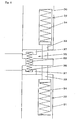
- Fig. 3 shows an enlarged view of a part "A" of Fig. 2.
- Fig. 4(a) shows a plain view indicating an embodiment of an arrangement of
compression coil springs - Fig. 4(b) shows a plain view indicating another embodiment of an arrangement of the
compression coil springs - Fig. 4(c) shows a plain view indicating another embodiment of an arrangement of the
compression coil springs - Fig. 5(a) shows a cross section of an elevational view indicating a state before squeezing foundry sand in an embodiment of this invention.
- Fig. 5(b) shows a cross section of an elevational view indicating a state while squeezing foundry sand in an embodiment of this invention.
- Fig. 6 shows an enlarged view of a part "B" of Fig. 5(a).
- Fig. 7(a) shows a plain view indicating an embodiment of an arrangement of
compression coil springs - Fig. 7(b) shows a plain view indicating another embodiment of an arrangement of the
compression coil springs - Fig. 7(c) shows a plain view indicating another embodiment of an arrangement of the
compression coil springs - Fig. 8(a) shows a cross section of an elevational view indicating a state before squeezing foundry sand in an embodiment of this invention.
- Fig. 8(b) shows a cross section of an elevational view indicating a state while squeezing foundry sand in an embodiment of this invention.
- Fig. 9 shows an enlarged view of a part "C" of Fig. 8(a).
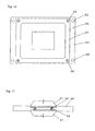
- Fig. 10 shows a plain view indicating an embodiment of an arrangement of
pins compression coil springs - Fig. 11 shows a cross section of an elevational view of another embodiment of this invention.
- The present invention, which uses an apparatus for molding an upper and a lower mold having no flask, is now explained in detail based on Fig. 2.
- The major portion of the apparatus for molding an upper and a lower mold having no flask, which is used in this invention, is shown in Fig. 2. The apparatus is comprised of:
- an upper and a
lower flask - a
match plate 3 that is held between the upper and thelower flask - an upper and a lower squeeze means 6, 7 having
squeeze plates lower flask match plate 3, - an upper and a lower lifting and lowering
frame -
cylinders frame 13, to press thelower flask 2 toward thematch plate 3. - In this invention the apparatus for molding molds which uses the match plate can be used regardless of whether the molds have a flask.
- Further, this invention can be applied to an apparatus for molding molds having not only one set of flasks, but also two sets of flasks.
- The squeeze means of this invention is comprised of actuators and squeeze plates or squeeze feet. The squeeze means can individually squeeze the foundry sand. The actuators that are driven by hydraulic pressure, air pressure, and electric motors can be used as the actuators. It is preferable to use the actuators driven by the hydraulic pressure from the aspect of the magnitude of the output of the power. It is further preferable to use the actuators driven by the electric motors since they need no piping system for the hydraulic pressure.
- In this invention, it is preferable to use green sand as foundry sand, which green sand uses bentonite as a binder.
- Below, an embodiment for a method for squeezing foundry sand and a match plate of this invention is explained in detail based on Figs. 1-4.
- An expanding and contracting means 8 is disposed at the peripheral border of the pattern portion of the
body 3a of the match plate as shown in Figs. 2-4, wherein the expanding and contracting means 8 can be expanded and contracted by being pressed with end surfaces of an upper and alower flask match plate 3. As shown in Fig. 3, the expanding and contracting means 8 is comprised of a plurality of compression coil-springs holes body 3a of the match plate, andsupport members springs springs support members body 3a of the match plate. - As shown in Fig. 4, it is possible to dispose a plurality of the compression coil-
springs lower flask - Below, the method for molding molds by using the apparatus of
embodiment 1 is explained in detail. - The foundry sand is filled in the upper and the lower molding space defined by a
match plate 3, an upper and alower flask lower squeeze plate lower squeeze plate springs match plate 3 are compressed by pressing thelower flask 2 toward thematch plate 3 by causing thecylinders springs match plate 3 moves relatively toward the upper and thelower squeeze plate frame cylinders lower flask springs match plate 3. - Below, an embodiment using another expanding and contracting means is explained based on Figs. 5-7. The expanding and contracting means 20 is disposed at the peripheral border of the pattern portion of the
match plate 21 as shown in Figs. 5-7, wherein the expanding and contracting means 20 can be expanded and contracted by being pressed with the end surfaces of an upper and alower flask match plate 21. As shown in Fig. 6, the expanding and contracting means 20 is comprised of a plurality of compression coil-springs holes match plate 21, andsupport members springs springs springs - arranging them at the entire circumference of the peripheral border of the pattern portion at even intervals as shown in Fig. 7(a), arranging them at two longitudinal sides of the peripheral border of the pattern portion at even intervals as shown in Fig. 7(b) and arranging them at two lateral sides of the peripheral border of the pattern portion at even intervals as shown in Fig. 7(c). In all arrangements of the compression coil-springs explained above based on Figs. 7(a), (b), and (c), the total force of the coil-springs should be more than the force that can support the weight of the upper and the lower
-
flask - Below, the method for molding molds by using the apparatus of
embodiment 2 is explained in detail. - The foundry sand is filled in the upper and the lower molding space defined by a
match plate 21, an upper and alower flask lower squeeze plate lower squeeze plate springs match plate 21 are compressed by pressing thelower flask 2 toward thematch plate 21 until the ends of thesupport members match plate 21. When the compression coil-springs match plate 21 moves relatively toward the upper and thelower squeeze plate - Below, an embodiment using another expanding and contracting means is explained based on Figs. 8 - 10. The first expanding and contracting means 32 is disposed at the end surfaces of the upper and the
lower flask match plate 21, as shown in Figs. 8-10, wherein the first expanding and contracting means 32 can be expanded and contracted by being pressed with the end surfaces of an upper and alower flask match plate 21. As shown in Fig. 9, the first expanding and contracting means 32 is comprised ofpins lower flask springs pins pins match plate 21. Thepins match plate 21 as shown in Fig. 10. - The second expanding and contracting means 35 is disposed at the peripheral border of the pattern portion of the
match plate 21 as shown in Figs. 8-10. The second expanding and contracting means 35 can be expanded and contracted by being pressed with end surfaces of an upper and alower flask match plate 21. As shown in Fig. 9, the second expanding and contracting means 35 is comprised of a plurality of compression coil-springs holes match plate 21, andsupport members springs springs support members - Below, the method for molding molds by using the apparatus of
embodiment 3 is explained in detail. - The foundry sand is filled in the upper and the lower molding space defined by a
match plate 21, an upper and alower flask lower squeeze plate lower squeeze plate springs lower flask 31 toward thematch plate 21 until the ends of thesupport members match plate 21. Thepins lower flask springs match plate 21 move relatively toward the upper and thelower squeeze plate springs - Since the compression coil-springs of the first expanding and contracting means 32 are disposed in the upper and the
lower flask - In the above three embodiments, the foundry sand in the upper and the lower molding space is squeezed by the relative movement between the upper and the lower flask and the pattern portion of the match plate. However, the method for squeezing the foundry sand is not restricted to these embodiments. It is also possible to squeeze the foundry sand in the upper and the lower molding space by individually moving the
pattern portions match plate 40 by any of theactuators - Further, in the above three embodiments, while squeezing the foundry sand in the upper and the lower molding space by causing the upper and the
lower squeeze plates - In the above three embodiments, the methods use compression coil-springs as the expanding and contracting means. However, the expanding and contracting means is not restricted to the compression coil-springs. It is also possible to use hydraulic cylinders or gas springs as the expanding and contracting means.
- This invention can be widely applied to a molding machine having a match plate, such as a molding machine producing a mold having a flask or having no flask. Further, while the foundry sand is filled or squeezed, it is possible to freely determine the position of the upper and the lower flask. For example, the upper and the lower flask can be arranged horizontally or vertically. Further, it is possible to cause the relative position of the upper and the lower flask at the time when the foundry sand is filled to differ from that when it is squeezed.
Claims (10)
- A method for squeezing foundry sand filled in an upper and a lower molding space defined by a match plate, an upper and a lower flask, and an upper and a lower squeeze plate, comprising:a first squeezing step to squeeze the foundry sand in the upper and the lower molding space by causing the upper and the lower squeeze plate to further approach each other, anda second squeezing step to squeeze the foundry sand in the upper and the lower molding space by causing the pattern portions of the match plate to move to each of the upper and the lower squeeze plate.
- A method for squeezing foundry sand filled in an upper and a lower molding space defined by a match plate, an upper and a lower flask, and an upper and a lower squeeze plate, comprising:a first squeezing step to squeeze the foundry sand in the upper and the lower molding space by causing the upper and the lower squeeze plate to further approach each other, anda second squeezing step to squeeze the foundry sand in the upper and the lower molding space by causing the patterns of the pattern portions of the match plate and the plate of the pattern portions to move to each of the upper and the lower squeeze plate by means of causing the upper and the lower flask to further approach each other.
- A method for squeezing foundry sand filled in an upper and a lower molding space defined by a match plate, an upper and a lower flask, and an upper and a lower squeeze plate, comprising:a first squeezing step to squeeze the foundry sand in the upper and the lower molding space by causing the upper and the lower squeeze plate to further approach each other, while maintaining a constant distance between the upper and the lower flask, anda second squeezing step to squeeze the foundry sand in the upper and the lower molding space by causing the patterns of the pattern portions of the match plate and the plate of the pattern portions to move to each of the upper and the lower squeeze plate by means of causing the upper and the lower flask to further approach each other.
- A match plate for squeezing foundry sand filled in an upper and a lower molding space defined by the match plate, an upper and a lower flask, and an upper and a lower squeeze plate, comprising:a pattern portion disposed at both sides of the match plate, wherein both sides contact end surfaces of the upper and the lower flask, andan expanding and contracting means disposed at the peripheral border of the pattern portion, wherein the expanding and contracting means can be expanded and contracted by being pressed by the end surfaces of the upper and the lower flask opposing the match plate.
- A match plate for squeezing foundry sand filled in an upper and a lower molding space defined by the match plate, an upper and a lower flask, and an upper and a lower squeeze plate, comprising:a pattern portion disposed at both sides of the match plate, wherein both sides contact end surfaces of the upper and the lower flask, andat least one actuator to cause the pattern of the pattern portion to individually move from the plate of the pattern portion, or at least one actuator to cause the plate of the pattern portion to individually move from the pattern of the pattern portion.
- A match plate for squeezing foundry sand filled in an upper and a lower molding space defined by the match plate, an upper and a lower flask, and an upper and a lower squeeze plate, comprising:a pattern portion disposed at both sides of the match plate, wherein both sides contact end surfaces of the upper and the lower flask, andat least one actuator to cause the pattern and the plate of the pattern portion to move toward the upper and the lower squeeze plate.
- A method for squeezing foundry sand, comprising:a filling step to fill an upper and a lower molding space defined by any of the match plates of claims 4, 5, and 6, an upper and a lower flask, and an upper and a lower squeeze plate with the foundry sand,a first squeezing step to squeeze the foundry sand in the upper and lower molding space by causing the upper and the lower squeeze plate to further approach each other, anda second squeezing step to squeeze the foundry sand in the upper and the lower molding space by causing the pattern and/or the plate of the pattern portions of the match plate to move to the upper and the lower squeeze plate.
- An upper and a lower flask for squeezing foundry sand filled in an upper and a lower molding space defined by a match plate, the upper and the lower flask, and an upper and a lower squeeze plate, comprising:a plurality of pins contacting both sides of the match plate, andan expanding and contracting means to expand and contract the pins by pressing them between the upper and the lower flask and both sides of the match plate.
- A method for squeezing foundry sand filled in an upper and a lower molding space defined by a match plate, an upper and a lower flask, and an upper and a lower squeeze plate, comprising:a first squeezing step to squeeze the foundry sand in the upper and the lower molding space by causing the upper and the lower squeeze plate to further approach each other, anda second squeezing step to squeeze the foundry sand in the upper and the lower molding space by causing the patterns of the pattern portions of the match plate and the plate of the pattern portions to move to the upper and the lower squeeze plate by means of causing the upper and the lower flask to further approach each other, wherein the upper and the lower flask are comprised of:a plurality of pins contacting both sides of the match plate, andan expanding and contracting means to expand and contract the pins by pressing them between the upper and the lower flask and both sides of the match plate.
- A method for squeezing foundry sand filled in an upper and a lower molding space defined by a match plate, an upper and a lower flask, and an upper and a lower squeeze plate, comprising:a first squeezing step to squeeze the foundry sand in the upper and the lower molding space by causing the upper and the lower squeeze plate to further approach each other, anda second squeezing step to squeeze the foundry sand in the upper and the lower molding space by causing the patterns of the pattern portions of the match plate and the plate of the pattern portions to move to each of the upper and the lower squeeze plate by means of causing the upper and the lower flask to further approach each other, wherein the upper and the lower flask is comprised of:a plurality of pins contacting both sides of the match plate, andan expanding and contracting means to expand and contract the pins by pressing them between the upper and the lower flask and both sides of the match plate,and wherein the match plate is any of the match plates of claims 4, 5, and 6.
Applications Claiming Priority (3)
| Application Number | Priority Date | Filing Date | Title |
|---|---|---|---|
| JP2004133547 | 2004-04-28 | ||
| JP2005119147 | 2005-04-18 | ||
| PCT/JP2005/007969 WO2005105339A1 (en) | 2004-04-28 | 2005-04-27 | Method of squeezing foundry sand, match plate, and upper and lower flasks |
Publications (3)
| Publication Number | Publication Date |
|---|---|
| EP1741504A1 true EP1741504A1 (en) | 2007-01-10 |
| EP1741504A4 EP1741504A4 (en) | 2007-09-12 |
| EP1741504B1 EP1741504B1 (en) | 2009-12-02 |
Family
ID=35241486
Family Applications (1)
| Application Number | Title | Priority Date | Filing Date |
|---|---|---|---|
| EP05736656A Expired - Lifetime EP1741504B1 (en) | 2004-04-28 | 2005-04-27 | Method and apparatus for squeezing foundry sand |
Country Status (12)
| Country | Link |
|---|---|
| US (1) | US7448429B2 (en) |
| EP (1) | EP1741504B1 (en) |
| JP (1) | JP4301292B2 (en) |
| KR (1) | KR100863104B1 (en) |
| CN (1) | CN1968770B (en) |
| AT (1) | ATE450330T1 (en) |
| BR (1) | BRPI0510454B1 (en) |
| DE (1) | DE602005018034D1 (en) |
| DK (1) | DK1741504T3 (en) |
| EA (1) | EA008631B1 (en) |
| MX (1) | MXPA06012488A (en) |
| WO (1) | WO2005105339A1 (en) |
Cited By (1)
| Publication number | Priority date | Publication date | Assignee | Title |
|---|---|---|---|---|
| EP2324941B1 (en) | 2008-08-07 | 2017-05-10 | Loramendi, S.COOP. | Device for actuating a closure plate in a vertical boxless mould casting machine and machine comprising said device |
Families Citing this family (3)
| Publication number | Priority date | Publication date | Assignee | Title |
|---|---|---|---|---|
| JP5076670B2 (en) * | 2006-08-04 | 2012-11-21 | 新東工業株式会社 | Frameless mold making machine |
| DK1935533T3 (en) * | 2006-12-18 | 2010-09-20 | Sintokogio Ltd | molding machine |
| CN107685138B (en) * | 2017-09-21 | 2024-01-30 | 江苏康柏斯机械科技有限公司 | Casting sand box |
Family Cites Families (15)
| Publication number | Priority date | Publication date | Assignee | Title |
|---|---|---|---|---|
| US365711A (en) * | 1887-06-28 | Haeeis taboe | ||
| US485764A (en) * | 1892-11-08 | Mulder s flask | ||
| US3406738A (en) * | 1967-04-06 | 1968-10-22 | Heatherwill Co | Automatic matchplate moulding machine |
| DE2558801C3 (en) * | 1974-04-19 | 1982-04-15 | Hitachi Metals, Ltd., Tokyo | Molding device for producing box-less molds |
| JPS5823180B2 (en) * | 1981-02-26 | 1983-05-13 | 株式会社 池田製作所 | Sand blowing device in automatic molding machine |
| JPS5924552A (en) | 1982-07-30 | 1984-02-08 | Sintokogio Ltd | Simultaneous forming machine of flaskless type top and bottom molds |
| JPS60158949A (en) * | 1984-01-30 | 1985-08-20 | Mitsubishi Heavy Ind Ltd | Method and device for forming casting mold |
| JP2772859B2 (en) * | 1990-07-27 | 1998-07-09 | 新東工業株式会社 | Frameless mold making machine |
| US5125449A (en) | 1991-01-02 | 1992-06-30 | Taiyo Chuki Co., Ltd. | Improved molding machine |
| JPH0641942U (en) | 1992-11-27 | 1994-06-03 | 新東工業株式会社 | Simultaneous molding machine for upper and lower molds |
| JP3092764B2 (en) | 1993-03-26 | 2000-09-25 | 新東工業株式会社 | Blow molding method |
| JPH08187544A (en) | 1994-12-28 | 1996-07-23 | Kooyoo:Kk | Sand mold release agent injection device |
| JP2000167647A (en) * | 1998-12-04 | 2000-06-20 | Taiyo Machinery Co Ltd | Automatic vibration molding machine for green mold |
| JP3342673B2 (en) | 1999-04-30 | 2002-11-11 | メタルエンジニアリング株式会社 | Mold molding apparatus and molding method |
| JP3459913B2 (en) | 2001-06-12 | 2003-10-27 | メタルエンジニアリング株式会社 | Method and apparatus for filling molding sand in frameless molding apparatus |
-
2005
- 2005-04-27 WO PCT/JP2005/007969 patent/WO2005105339A1/en not_active Ceased
- 2005-04-27 CN CN2005800197150A patent/CN1968770B/en not_active Expired - Lifetime
- 2005-04-27 AT AT05736656T patent/ATE450330T1/en not_active IP Right Cessation
- 2005-04-27 DK DK05736656.9T patent/DK1741504T3/en active
- 2005-04-27 KR KR1020067024634A patent/KR100863104B1/en not_active Expired - Fee Related
- 2005-04-27 JP JP2006512797A patent/JP4301292B2/en not_active Expired - Lifetime
- 2005-04-27 BR BRPI0510454-8A patent/BRPI0510454B1/en not_active IP Right Cessation
- 2005-04-27 MX MXPA06012488A patent/MXPA06012488A/en active IP Right Grant
- 2005-04-27 EA EA200601996A patent/EA008631B1/en not_active IP Right Cessation
- 2005-04-27 DE DE602005018034T patent/DE602005018034D1/en not_active Expired - Lifetime
- 2005-04-27 US US11/587,633 patent/US7448429B2/en not_active Expired - Lifetime
- 2005-04-27 EP EP05736656A patent/EP1741504B1/en not_active Expired - Lifetime
Cited By (2)
| Publication number | Priority date | Publication date | Assignee | Title |
|---|---|---|---|---|
| EP2324941B1 (en) | 2008-08-07 | 2017-05-10 | Loramendi, S.COOP. | Device for actuating a closure plate in a vertical boxless mould casting machine and machine comprising said device |
| EP2324941B2 (en) † | 2008-08-07 | 2020-02-19 | Loramendi, S.COOP. | Device for actuating a closure plate in a vertical boxless mould casting machine and machine comprising said device |
Also Published As
| Publication number | Publication date |
|---|---|
| JP4301292B2 (en) | 2009-07-22 |
| CN1968770A (en) | 2007-05-23 |
| WO2005105339A1 (en) | 2005-11-10 |
| BRPI0510454A (en) | 2007-10-30 |
| EA008631B1 (en) | 2007-06-29 |
| EP1741504A4 (en) | 2007-09-12 |
| DK1741504T3 (en) | 2010-04-06 |
| US7448429B2 (en) | 2008-11-11 |
| DE602005018034D1 (en) | 2010-01-14 |
| EA200601996A1 (en) | 2007-02-27 |
| BRPI0510454B1 (en) | 2013-04-09 |
| EP1741504B1 (en) | 2009-12-02 |
| KR20070012511A (en) | 2007-01-25 |
| JPWO2005105339A1 (en) | 2008-03-13 |
| ATE450330T1 (en) | 2009-12-15 |
| MXPA06012488A (en) | 2007-01-31 |
| US20070227684A1 (en) | 2007-10-04 |
| CN1968770B (en) | 2010-12-22 |
| KR100863104B1 (en) | 2008-10-13 |
Similar Documents
| Publication | Publication Date | Title |
|---|---|---|
| EP2514540B1 (en) | Molding process for simultaneously making an upper mold and a lower mold and a flaskless molding machine | |
| CN201760499U (en) | Backward deep drawing die with outer edge subject to back pressure of forward pressure belt | |
| CN209550365U (en) | In-mold stripping assembly and mold | |
| EP1741504B1 (en) | Method and apparatus for squeezing foundry sand | |
| JP3407879B2 (en) | Method and apparatus for filling and compressing molding sand | |
| JP3687492B2 (en) | Press molding method of dielectric block | |
| JP4427770B2 (en) | Method and apparatus for compressing foundry sand | |
| CN110534332A (en) | Sintered magnet preparation method and its pressure forming machine | |
| JP2000135599A (en) | Heat press equipment | |
| KR100297192B1 (en) | Movable frame type press | |
| CN210450968U (en) | Material taking manipulator for powder metallurgy forming device | |
| CN222552008U (en) | A steel bar pressing device | |
| JP4352395B2 (en) | Method and apparatus for compressing foundry sand | |
| CN220145776U (en) | Hydraulic clamp | |
| CN213793823U (en) | Mould of multifunctional environment-friendly equipment | |
| JP7841679B1 (en) | Apparatus for manufacturing powder molded bodies, and method for manufacturing powder molded bodies | |
| JP3453408B2 (en) | Press device with clamping means | |
| JP3329691B2 (en) | Sand molding method and apparatus | |
| JPH01119604A (en) | Powder molding method | |
| CN110405126B (en) | Forging and pressing device for supporting ring production | |
| JP6015495B2 (en) | Powder molding equipment | |
| JPS6135301Y2 (en) | ||
| JP3262201B2 (en) | Mold making method | |
| JP3224077B2 (en) | Mold making method | |
| JPH09157702A (en) | Compacting equipment |
Legal Events
| Date | Code | Title | Description |
|---|---|---|---|
| PUAI | Public reference made under article 153(3) epc to a published international application that has entered the european phase |
Free format text: ORIGINAL CODE: 0009012 |
|
| 17P | Request for examination filed |
Effective date: 20061018 |
|
| AK | Designated contracting states |
Kind code of ref document: A1 Designated state(s): AT BE BG CH CY CZ DE DK EE ES FI FR GB GR HU IE IS IT LI LT LU MC NL PL PT RO SE SI SK TR |
|
| DAX | Request for extension of the european patent (deleted) | ||
| A4 | Supplementary search report drawn up and despatched |
Effective date: 20070814 |
|
| 17Q | First examination report despatched |
Effective date: 20081124 |
|
| GRAP | Despatch of communication of intention to grant a patent |
Free format text: ORIGINAL CODE: EPIDOSNIGR1 |
|
| RTI1 | Title (correction) |
Free format text: METHOD AND APPARATUS FOR SQUEEZING FOUNDRY SAND |
|
| GRAS | Grant fee paid |
Free format text: ORIGINAL CODE: EPIDOSNIGR3 |
|
| GRAA | (expected) grant |
Free format text: ORIGINAL CODE: 0009210 |
|
| AK | Designated contracting states |
Kind code of ref document: B1 Designated state(s): AT BE BG CH CY CZ DE DK EE ES FI FR GB GR HU IE IS IT LI LT LU MC NL PL PT RO SE SI SK TR |
|
| REG | Reference to a national code |
Ref country code: GB Ref legal event code: FG4D |
|
| REG | Reference to a national code |
Ref country code: CH Ref legal event code: EP |
|
| REG | Reference to a national code |
Ref country code: IE Ref legal event code: FG4D |
|
| REF | Corresponds to: |
Ref document number: 602005018034 Country of ref document: DE Date of ref document: 20100114 Kind code of ref document: P |
|
| REG | Reference to a national code |
Ref country code: DK Ref legal event code: T3 |
|
| REG | Reference to a national code |
Ref country code: NL Ref legal event code: VDEP Effective date: 20091202 |
|
| PG25 | Lapsed in a contracting state [announced via postgrant information from national office to epo] |
Ref country code: SE Free format text: LAPSE BECAUSE OF FAILURE TO SUBMIT A TRANSLATION OF THE DESCRIPTION OR TO PAY THE FEE WITHIN THE PRESCRIBED TIME-LIMIT Effective date: 20091202 Ref country code: FI Free format text: LAPSE BECAUSE OF FAILURE TO SUBMIT A TRANSLATION OF THE DESCRIPTION OR TO PAY THE FEE WITHIN THE PRESCRIBED TIME-LIMIT Effective date: 20091202 Ref country code: LT Free format text: LAPSE BECAUSE OF FAILURE TO SUBMIT A TRANSLATION OF THE DESCRIPTION OR TO PAY THE FEE WITHIN THE PRESCRIBED TIME-LIMIT Effective date: 20091202 |
|
| LTIE | Lt: invalidation of european patent or patent extension |
Effective date: 20091202 |
|
| PG25 | Lapsed in a contracting state [announced via postgrant information from national office to epo] |
Ref country code: SI Free format text: LAPSE BECAUSE OF FAILURE TO SUBMIT A TRANSLATION OF THE DESCRIPTION OR TO PAY THE FEE WITHIN THE PRESCRIBED TIME-LIMIT Effective date: 20091202 Ref country code: PL Free format text: LAPSE BECAUSE OF FAILURE TO SUBMIT A TRANSLATION OF THE DESCRIPTION OR TO PAY THE FEE WITHIN THE PRESCRIBED TIME-LIMIT Effective date: 20091202 Ref country code: CY Free format text: LAPSE BECAUSE OF FAILURE TO SUBMIT A TRANSLATION OF THE DESCRIPTION OR TO PAY THE FEE WITHIN THE PRESCRIBED TIME-LIMIT Effective date: 20091202 |
|
| PG25 | Lapsed in a contracting state [announced via postgrant information from national office to epo] |
Ref country code: AT Free format text: LAPSE BECAUSE OF FAILURE TO SUBMIT A TRANSLATION OF THE DESCRIPTION OR TO PAY THE FEE WITHIN THE PRESCRIBED TIME-LIMIT Effective date: 20091202 |
|
| PG25 | Lapsed in a contracting state [announced via postgrant information from national office to epo] |
Ref country code: NL Free format text: LAPSE BECAUSE OF FAILURE TO SUBMIT A TRANSLATION OF THE DESCRIPTION OR TO PAY THE FEE WITHIN THE PRESCRIBED TIME-LIMIT Effective date: 20091202 Ref country code: EE Free format text: LAPSE BECAUSE OF FAILURE TO SUBMIT A TRANSLATION OF THE DESCRIPTION OR TO PAY THE FEE WITHIN THE PRESCRIBED TIME-LIMIT Effective date: 20091202 Ref country code: BG Free format text: LAPSE BECAUSE OF FAILURE TO SUBMIT A TRANSLATION OF THE DESCRIPTION OR TO PAY THE FEE WITHIN THE PRESCRIBED TIME-LIMIT Effective date: 20100302 Ref country code: PT Free format text: LAPSE BECAUSE OF FAILURE TO SUBMIT A TRANSLATION OF THE DESCRIPTION OR TO PAY THE FEE WITHIN THE PRESCRIBED TIME-LIMIT Effective date: 20100402 Ref country code: RO Free format text: LAPSE BECAUSE OF FAILURE TO SUBMIT A TRANSLATION OF THE DESCRIPTION OR TO PAY THE FEE WITHIN THE PRESCRIBED TIME-LIMIT Effective date: 20091202 Ref country code: ES Free format text: LAPSE BECAUSE OF FAILURE TO SUBMIT A TRANSLATION OF THE DESCRIPTION OR TO PAY THE FEE WITHIN THE PRESCRIBED TIME-LIMIT Effective date: 20100313 Ref country code: IS Free format text: LAPSE BECAUSE OF FAILURE TO SUBMIT A TRANSLATION OF THE DESCRIPTION OR TO PAY THE FEE WITHIN THE PRESCRIBED TIME-LIMIT Effective date: 20100402 |
|
| PG25 | Lapsed in a contracting state [announced via postgrant information from national office to epo] |
Ref country code: BE Free format text: LAPSE BECAUSE OF FAILURE TO SUBMIT A TRANSLATION OF THE DESCRIPTION OR TO PAY THE FEE WITHIN THE PRESCRIBED TIME-LIMIT Effective date: 20091202 Ref country code: SK Free format text: LAPSE BECAUSE OF FAILURE TO SUBMIT A TRANSLATION OF THE DESCRIPTION OR TO PAY THE FEE WITHIN THE PRESCRIBED TIME-LIMIT Effective date: 20091202 |
|
| PLBE | No opposition filed within time limit |
Free format text: ORIGINAL CODE: 0009261 |
|
| STAA | Information on the status of an ep patent application or granted ep patent |
Free format text: STATUS: NO OPPOSITION FILED WITHIN TIME LIMIT |
|
| PG25 | Lapsed in a contracting state [announced via postgrant information from national office to epo] |
Ref country code: GR Free format text: LAPSE BECAUSE OF FAILURE TO SUBMIT A TRANSLATION OF THE DESCRIPTION OR TO PAY THE FEE WITHIN THE PRESCRIBED TIME-LIMIT Effective date: 20100303 |
|
| 26N | No opposition filed |
Effective date: 20100903 |
|
| PG25 | Lapsed in a contracting state [announced via postgrant information from national office to epo] |
Ref country code: MC Free format text: LAPSE BECAUSE OF NON-PAYMENT OF DUE FEES Effective date: 20100430 |
|
| REG | Reference to a national code |
Ref country code: CH Ref legal event code: PL |
|
| GBPC | Gb: european patent ceased through non-payment of renewal fee |
Effective date: 20100427 |
|
| REG | Reference to a national code |
Ref country code: FR Ref legal event code: ST Effective date: 20101230 |
|
| PG25 | Lapsed in a contracting state [announced via postgrant information from national office to epo] |
Ref country code: IE Free format text: LAPSE BECAUSE OF NON-PAYMENT OF DUE FEES Effective date: 20100427 |
|
| PG25 | Lapsed in a contracting state [announced via postgrant information from national office to epo] |
Ref country code: CH Free format text: LAPSE BECAUSE OF NON-PAYMENT OF DUE FEES Effective date: 20100430 Ref country code: LI Free format text: LAPSE BECAUSE OF NON-PAYMENT OF DUE FEES Effective date: 20100430 |
|
| PG25 | Lapsed in a contracting state [announced via postgrant information from national office to epo] |
Ref country code: IT Free format text: LAPSE BECAUSE OF FAILURE TO SUBMIT A TRANSLATION OF THE DESCRIPTION OR TO PAY THE FEE WITHIN THE PRESCRIBED TIME-LIMIT Effective date: 20091202 Ref country code: GB Free format text: LAPSE BECAUSE OF NON-PAYMENT OF DUE FEES Effective date: 20100427 |
|
| PG25 | Lapsed in a contracting state [announced via postgrant information from national office to epo] |
Ref country code: FR Free format text: LAPSE BECAUSE OF NON-PAYMENT OF DUE FEES Effective date: 20100430 |
|
| PG25 | Lapsed in a contracting state [announced via postgrant information from national office to epo] |
Ref country code: LU Free format text: LAPSE BECAUSE OF NON-PAYMENT OF DUE FEES Effective date: 20100427 Ref country code: HU Free format text: LAPSE BECAUSE OF FAILURE TO SUBMIT A TRANSLATION OF THE DESCRIPTION OR TO PAY THE FEE WITHIN THE PRESCRIBED TIME-LIMIT Effective date: 20100603 |
|
| PG25 | Lapsed in a contracting state [announced via postgrant information from national office to epo] |
Ref country code: TR Free format text: LAPSE BECAUSE OF FAILURE TO SUBMIT A TRANSLATION OF THE DESCRIPTION OR TO PAY THE FEE WITHIN THE PRESCRIBED TIME-LIMIT Effective date: 20091202 |
|
| PGFP | Annual fee paid to national office [announced via postgrant information from national office to epo] |
Ref country code: DK Payment date: 20230421 Year of fee payment: 19 Ref country code: CZ Payment date: 20230419 Year of fee payment: 19 |
|
| PGFP | Annual fee paid to national office [announced via postgrant information from national office to epo] |
Ref country code: DE Payment date: 20240418 Year of fee payment: 20 |
|
| REG | Reference to a national code |
Ref country code: DK Ref legal event code: EBP Effective date: 20240430 |
|
| PG25 | Lapsed in a contracting state [announced via postgrant information from national office to epo] |
Ref country code: CZ Free format text: LAPSE BECAUSE OF NON-PAYMENT OF DUE FEES Effective date: 20240427 |
|
| PG25 | Lapsed in a contracting state [announced via postgrant information from national office to epo] |
Ref country code: CZ Free format text: LAPSE BECAUSE OF NON-PAYMENT OF DUE FEES Effective date: 20240427 |
|
| PG25 | Lapsed in a contracting state [announced via postgrant information from national office to epo] |
Ref country code: DK Free format text: LAPSE BECAUSE OF NON-PAYMENT OF DUE FEES Effective date: 20240430 |
|
| REG | Reference to a national code |
Ref country code: DE Ref legal event code: R071 Ref document number: 602005018034 Country of ref document: DE |