EP1741350A1 - A unit for feeding filters to a filter tip attachment machine - Google Patents
A unit for feeding filters to a filter tip attachment machine Download PDFInfo
- Publication number
- EP1741350A1 EP1741350A1 EP06116457A EP06116457A EP1741350A1 EP 1741350 A1 EP1741350 A1 EP 1741350A1 EP 06116457 A EP06116457 A EP 06116457A EP 06116457 A EP06116457 A EP 06116457A EP 1741350 A1 EP1741350 A1 EP 1741350A1
- Authority
- EP
- European Patent Office
- Prior art keywords
- unit
- hopper
- filters
- sectors
- filter
- Prior art date
- Legal status (The legal status is an assumption and is not a legal conclusion. Google has not performed a legal analysis and makes no representation as to the accuracy of the status listed.)
- Granted
Links
Images



Classifications
-
- A—HUMAN NECESSITIES
- A24—TOBACCO; CIGARS; CIGARETTES; SIMULATED SMOKING DEVICES; SMOKERS' REQUISITES
- A24C—MACHINES FOR MAKING CIGARS OR CIGARETTES
- A24C5/00—Making cigarettes; Making tipping materials for, or attaching filters or mouthpieces to, cigars or cigarettes
- A24C5/32—Separating, ordering, counting or examining cigarettes; Regulating the feeding of tobacco according to rod or cigarette condition
- A24C5/322—Transporting cigarettes during manufacturing
- A24C5/323—Transporting cigarettes during manufacturing pneumatically
-
- A—HUMAN NECESSITIES
- A24—TOBACCO; CIGARS; CIGARETTES; SIMULATED SMOKING DEVICES; SMOKERS' REQUISITES
- A24C—MACHINES FOR MAKING CIGARS OR CIGARETTES
- A24C5/00—Making cigarettes; Making tipping materials for, or attaching filters or mouthpieces to, cigars or cigarettes
- A24C5/47—Attaching filters or mouthpieces to cigars or cigarettes, e.g. inserting filters into cigarettes or their mouthpieces
- A24C5/478—Transport means for filter- or cigarette-rods in view of their assembling
Definitions
- the present invention relates to a unit for feeding filters to a filter tip attachment machine.
- the invention relates to a filter feed unit equipped with a holding hopper, located between the outfeed of a filter maker and the inlet of a pneumatic feed duct connected in turn to a filter tip attachment machine.
- filters turned out by the maker are directed into the hopper, which functions as a reservoir, by way of a single infeed point in the top part of the selfsame hopper.
- the filters are collected en masse internally of the hopper, ordered horizontally and side by side, ready to be transferred to the pneumatic feed duct.
- the hopper presents a single internal compartment accommodating filters of one type, hence all of the same diameter and the same length.
- the transfer of the filters from the outlet of the hopper to the inlet of the feed duct is brought about, again conventionally, through the agency of transfer means comprising a plurality of drums rotating about respective horizontal axes parallel to the axes of the filters and located in the lower part of the hopper.
- the drums are furnished around the periphery with aspirating flutes, disposed parallel to the axis of the drum, each one of which is able to accommodate a single filter.
- the filters are taken up by the aforementioned flutes and rotated through 180° on the drums, passing singly and in succession into a transfer station where they are drawn into a flow of compressed air and conveyed along the pneumatic feed duct to the filter tip attachment machine.
- a conventional filter feed unit is fed generally, during operation, with filters of one length and one diameter.
- the space enclosed by the hopper can be varied, when not in operation, by displacing the back wall to adapt the depth of the selfsame hopper to the length of the incoming filters.
- each unit handles filters of just one type and is dedicated to a sole filter maker on the infeed side, and a sole filter tip attachment machine on the outfeed side.
- the filter feed unit can be used in conjunction with multiple filter tip attachment machines processing the same type of filter but operating at dissimilar speeds one from another. In this instance, different numbers of drums will be dedicated to the various downstream machines, according to their operating speed.
- the filter feed unit lacks versatility, since only one brand of filter can be handled, and a single unit can be used only with certain filter makers and filter tip attachment machines.
- the object of the present invention is to improve the versatility of a unit for feeding filters, by enabling it to handle filters of different lengths simultaneously.
- a further object of the invention is to render the filter feed unit suitable for use with multiple filter makers or filter tip attachment machines utilizing different sizes of filters or operating at dissimilar speeds.
- numeral 1 denotes a feed unit, in its entirety, by which filter plugs 2 are supplied to a filter tip attachment machine of conventional type, not illustrated.
- the unit 1 comprises a frame-like structure 3 with a lower base portion 4 incorporating bearers, ducts and control systems of familiar type not described further, and an upper portion carrying a hopper 5 delimited by a front wall 6 and a back wall 7, interconnected by two side walls 8 and 9.
- the side walls 8 and 9 include first segments rising vertically from the base portion, and second segments converging toward the top, so that when seen in longitudinal section, the hopper 5 presents the shape substantially of an upturned funnel.
- the front wall 6, made preferably of transparent material and appearing substantially rectangular in outline, is composed of two doors 6a and 6b that can be opened to allow inspection and servicing of the hopper 5 on the inside.
- the back wall 7, on the other hand, is delimited by the side walls 8 and 9 and therefore assumes the same upturned funnel shape as that of the hopper 5.
- the frame-like structure 3 further comprises a vertical bulkhead 10 carrying the hopper 5, facing the back wall 7 and connected to the side walls 8 and 9.
- Filter plugs 2 turned out by a filter maker (not illustrated), located upstream of the unit 1, are directed into the hopper 5 and allowed to collect one alongside another, disposed perpendicular to the front and back walls 6 and 7.
- the hopper 5 is delimited at the bottom by a plurality of drums 11, each set in rotation about a respective longitudinal axis 12 perpendicular to the front and back walls 6 and 7.
- Each drum 11 presents a plurality of aspirating axial flutes 13 arranged around the periphery in conventional manner and serving each to accommodate a single filter 2.
- the bottom part of the hopper 5 is enclosed by a plurality of transparent flaps (not illustrated) arranged one beside another.
- the flaps are located one directly in front of each drum 11, so that the drums 11 can be exposed and inspected singly in the event of a jam or malfunction occurring.
- each drum 11 presents a loading station 14 above, where the filters 2 are taken up singly and in succession by the peripheral axial flutes 13, and an unloading and transfer station 15 below, coinciding with the inlet of the pneumatic feed duct that links the unit 1 to the filter tip attachment machine (not illustrated).
- the hopper 5 further comprises means 16 by which to partition the storage space into at least two sectors 17, each serving at least one drum 11.
- Such means 16 are illustrated as at least one movable baffle 18 disposed vertically and parallel to the side walls 8 and 9.
- the baffle 18 is translatable along a direction parallel with the axes 12 of the drums 11 between a fully retracted position, outside of the hopper 5 and to the rear of the bulkhead 10, and a fully extended position inside the hopper 5, bridging the gap between the front wall 6 and the back wall 7.
- the bulkhead 10 is furnished with vertical slots 19 through which the baffles 18 are able to pass.
- the unit 1 is equipped with three baffles 18 by which the space internally of the hopper 5 can be divided into four sectors 17 appearing as two distinct identical pairs.
- the hopper 5 is symmetrical relative to a vertical axis coinciding with the central baffle 18, so that the two sectors 17a and 17b outermost are mutually identical and the two sectors 17c and 17d innermost are mutually identical.
- Each outer sector 17a and 17b serves two drums 11; each inner sector 17c and 17d serves a single drum 11.
- Each baffle 18 can be operated individually and independently of the others, allowing the hopper 5 to be partitioned as preferred and as may be most appropriate.
- the single sectors 17 operate independently of one another, and their allocation to the drums 11 can be selectively predetermined.
- baffles can be retracted or extended to produce the following configurations:
- the hopper is able to handle filters of different types simultaneously.
- the filter feed unit 1 is equipped further with means 20 by which to vary the size of at least one sector 17 in the partitioned hopper 5.
- the means 20 in question comprise at least one movable panel 21 associated with the back wall 7.
- each sector 17 presents one such movable panel 21 delimiting the rear of the sector 17 and coinciding with the back wall 7.
- Each panel 21 is translatable, remaining parallel to the front wall 6, in such a way as to vary the depth of the relative sector 17.
- the hopper is furnished with four panels 21 which, like the sectors 17, are arranged in two distinct identical pairs arranged symmetrically on either side of the vertical axis aforementioned.
- each single panel 21 is brought about independently relative to the movement of the others so that individual sectors 17 can be adapted to accommodate filters 2 of different length.
- a top part of the hopper 5 affords openings 22 to admit the filters 2.
- the hopper 5 presents three openings 22, namely a central opening 22a by way of which the two inner sectors 17c and 17d are filled, and two side openings 22b by way of which the two outer sectors 17a and 17b are filled.
- the top part of the hopper 5 is equipped further with a plurality of photocells 23, at least one to each sector 17, serving to monitor the level of the filters 2 amassed within the enclosure.
- the photocells 23 are wired to a control unit (not illustrated) operating in conjunction with the filter maker upstream of the feed unit 1, in such a way that when the sectors 17 fill up to a certain level, the flow of filters 2 from the maker to the hopper 5 will be suspended temporarily.
- the feed unit 1 is able to operate in a system incorporating multiple machines handling filters 2 of different sizes, given that the space encompassed by the hopper 5 is partitioned in such a way so as to create a plurality of sectors 17 operating independently of one another and in conjunction with respective drums 11.
- each drum 11 and to one side of the loading station 14 is an element 24 presenting a surface 24a angled downward toward the drum 11 and serving to restrict the cross sectional area of the passage afforded to the filters 2 at the selfsame station 14. This arrangement is designed to reduce the weight of the column of filters 2 bearing down on the loading station 14.
- the means 16 for partitioning the inside of the hopper 5 further comprise an actuator 25, as shown in figures 3 and 4, associated with the relative baffle 18 and connected rigidly to the vertical bulkhead 10 of the feed unit 1.
- the actuator 25 in question serves to bring about the sliding movement of the baffle 18, and consists in a pneumatic cylinder 26.
- Each baffle 18 presents a projection 18a that stays permanently outside the hopper 5 and carries a rectilinear hanger 27 engaging slidably with a linear track 28 of "C" profile connected to the bulkhead 10, externally of the hopper 5.
- the action of the cylinder 26 is transmitted to the projection 18a, likewise of "C" profile, by way of a bracket 29 anchored to the underside of the projection 18a.
- the projection 18a, the rectilinear carriage 27, the linear track 28 and the pneumatic piston 26 are positioned at the top end 19a of the slot 19.
- the projection 18a also limits the travel of the baffle 18 inasmuch as the underside, to which the bracket 29 is attached, is disposed transversely to the slot 19 and thus prevented by the bulkhead 10 from advancing further once the baffle 18 is fully inside the hopper 5.
- Each of the vertical slots 19 in which the baffles 18 slide back and forth is flanged by two matched guide plates 30 serving to ensure that the baffle 18 will not slip out of its correct position when fully retracted.
- means 20 for varying the size of at least one sector 17 of the hopper 5 will further comprise at least one drive unit 31 mounted to the vertical bulkhead 10 and associated with a respective movable panel 21, as illustrated in figure 3 and described hereinafter.
- Each such drive unit 31 is carried by a mounting plate 32 attached to the bulkhead 10 externally of the hopper 5 by way of a first stud 33a and a second stud 33b, both of which occupying a fixed position.
- the drive unit 31 comprises an electric motor 34 coupled to a speed reducer 35 driving a gear 36.
- the gear 36 is coupled in turn by way of a chain 37 or a belt with two further gears 38, also mounted to the bulkhead 10 on the outside of the hopper.
- Each mounting plate 32 is pivotable about the first stud 33a and affords a slot 39, engaged by the second stud 33b, which is lockable so as to secure the plate in the most advantageous position.
- the resulting mechanism allows a degree of movement to the drive unit 31, which is used to adjust the tension of the chain 37.
- Each of the two driven gears 38 presents a centre hole 40 coinciding with a respective hole in the bulkhead 10.
- Each hole 40 is engaged by an externally threaded rod 41 fastened rigidly to the surface of the panel 21 facing the bulkhead 10.
- each driven gear 38 Located between the rod 41 and the centre hole 40 of each driven gear 38 is a mechanism, such as a ballscrew, allowing the rod 41 to stroke back and forth through the hole 40 and displace the relative panel 21.
- a mechanism such as a ballscrew
- the first gear 36 is set in rotation by the electric motor 34 and transmits motion by way of the chain 37 to the other two gears 38.
- the angular motion of the two driven gears 38 is transmitted through the ballscrew mechanisms to the rods 41 and converted into linear motion, with the result that the panel 21 to which the rods are anchored will be pushed forward or drawn back.
- Each electric motor 34 is fitted with an encoder, not illustrated, that will determine the distance of the associated panel 21 from the front wall 6 of the hopper 5. Thus, it becomes possible to assign each sector 17 to a different type of filter 2 on the basis of length.
- control unit 42 such as will allow the position of the baffle 18 and of the panel 18 to be altered either automatically or in manual mode, by an operator, so as to adapt each sector 17 to the type of filter 2 accommodated.
- the single feed unit 1 can be linked both on the infeed and on the outfeed side to three different types of filter maker and filter tip attachment machine.
- the feed unit 1 can be linked to similar machines operating at different speeds.
Landscapes
- Cigarettes, Filters, And Manufacturing Of Filters (AREA)
- Manufacturing Of Cigar And Cigarette Tobacco (AREA)
- Filling Or Emptying Of Bunkers, Hoppers, And Tanks (AREA)
Abstract
Description
- The present invention relates to a unit for feeding filters to a filter tip attachment machine.
- In particular, the invention relates to a filter feed unit equipped with a holding hopper, located between the outfeed of a filter maker and the inlet of a pneumatic feed duct connected in turn to a filter tip attachment machine.
- Conventionally, filters turned out by the maker are directed into the hopper, which functions as a reservoir, by way of a single infeed point in the top part of the selfsame hopper. The filters are collected en masse internally of the hopper, ordered horizontally and side by side, ready to be transferred to the pneumatic feed duct.
- The hopper presents a single internal compartment accommodating filters of one type, hence all of the same diameter and the same length.
- The transfer of the filters from the outlet of the hopper to the inlet of the feed duct is brought about, again conventionally, through the agency of transfer means comprising a plurality of drums rotating about respective horizontal axes parallel to the axes of the filters and located in the lower part of the hopper.
- The drums are furnished around the periphery with aspirating flutes, disposed parallel to the axis of the drum, each one of which is able to accommodate a single filter.
- Gravitating from the reservoir, the filters are taken up by the aforementioned flutes and rotated through 180° on the drums, passing singly and in succession into a transfer station where they are drawn into a flow of compressed air and conveyed along the pneumatic feed duct to the filter tip attachment machine.
- A conventional filter feed unit is fed generally, during operation, with filters of one length and one diameter. The space enclosed by the hopper can be varied, when not in operation, by displacing the back wall to adapt the depth of the selfsame hopper to the length of the incoming filters.
- Thus, as already intimated, each unit handles filters of just one type and is dedicated to a sole filter maker on the infeed side, and a sole filter tip attachment machine on the outfeed side.
- Alternatively, the filter feed unit can be used in conjunction with multiple filter tip attachment machines processing the same type of filter but operating at dissimilar speeds one from another. In this instance, different numbers of drums will be dedicated to the various downstream machines, according to their operating speed.
- It will be seen from the foregoing outline that the filter feed unit lacks versatility, since only one brand of filter can be handled, and a single unit can be used only with certain filter makers and filter tip attachment machines.
- Moreover, it is not always possible to exploit all of the sets of drums by reason of the possible variations in operating speed of the downstream attachment machine, so that the output capacity of the machinery overall is limited.
- The object of the present invention is to improve the versatility of a unit for feeding filters, by enabling it to handle filters of different lengths simultaneously.
- A further object of the invention is to render the filter feed unit suitable for use with multiple filter makers or filter tip attachment machines utilizing different sizes of filters or operating at dissimilar speeds.
- The stated objects are realized in a unit for feeding filters to a filter tip attachment machine, as recited in
claim 1 appended and, preferably, in any other claim dependent directly or indirectly onclaim 1. - The invention will now be described in detail, by way of example, with the aid of the accompanying drawings, in which:
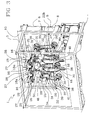
- figure 1 is a front perspective view of a unit for feeding filters according to the present invention, illustrated in a preferred embodiment;
- figure 2 is a schematic front elevation view of the preferred embodiment as in figure 1;
- figure 3 is a rear perspective view of the preferred embodiment as in figure 1;
- figure 4 is a schematic rear elevation view of the preferred embodiment as in figure 3.
- With reference to figure 1,
numeral 1 denotes a feed unit, in its entirety, by whichfilter plugs 2 are supplied to a filter tip attachment machine of conventional type, not illustrated. - The
unit 1 comprises a frame-like structure 3 with alower base portion 4 incorporating bearers, ducts and control systems of familiar type not described further, and an upper portion carrying ahopper 5 delimited by afront wall 6 and aback wall 7, interconnected by twoside walls - The
side walls hopper 5 presents the shape substantially of an upturned funnel. - The
front wall 6, made preferably of transparent material and appearing substantially rectangular in outline, is composed of twodoors hopper 5 on the inside. - The
back wall 7, on the other hand, is delimited by theside walls hopper 5. - The frame-
like structure 3 further comprises avertical bulkhead 10 carrying thehopper 5, facing theback wall 7 and connected to theside walls -
Filter plugs 2 turned out by a filter maker (not illustrated), located upstream of theunit 1, are directed into thehopper 5 and allowed to collect one alongside another, disposed perpendicular to the front andback walls - The
hopper 5 is delimited at the bottom by a plurality ofdrums 11, each set in rotation about a respectivelongitudinal axis 12 perpendicular to the front andback walls - Each
drum 11 presents a plurality of aspiratingaxial flutes 13 arranged around the periphery in conventional manner and serving each to accommodate asingle filter 2. - The bottom part of the
hopper 5 is enclosed by a plurality of transparent flaps (not illustrated) arranged one beside another. The flaps are located one directly in front of eachdrum 11, so that thedrums 11 can be exposed and inspected singly in the event of a jam or malfunction occurring. - As indicated in figure 1, each
drum 11 presents aloading station 14 above, where thefilters 2 are taken up singly and in succession by the peripheralaxial flutes 13, and an unloading andtransfer station 15 below, coinciding with the inlet of the pneumatic feed duct that links theunit 1 to the filter tip attachment machine (not illustrated). - The
hopper 5 further comprises means 16 by which to partition the storage space into at least twosectors 17, each serving at least onedrum 11.Such means 16 are illustrated as at least onemovable baffle 18 disposed vertically and parallel to theside walls - The
baffle 18 is translatable along a direction parallel with theaxes 12 of thedrums 11 between a fully retracted position, outside of thehopper 5 and to the rear of thebulkhead 10, and a fully extended position inside thehopper 5, bridging the gap between thefront wall 6 and theback wall 7. - Accordingly, the
bulkhead 10 is furnished withvertical slots 19 through which thebaffles 18 are able to pass. - In the preferred embodiment of figure 1, shown purely by way of example, the
unit 1 is equipped with threebaffles 18 by which the space internally of thehopper 5 can be divided into foursectors 17 appearing as two distinct identical pairs. Thehopper 5 is symmetrical relative to a vertical axis coinciding with thecentral baffle 18, so that the twosectors sectors outer sector drums 11; eachinner sector single drum 11. - Each
baffle 18 can be operated individually and independently of the others, allowing thehopper 5 to be partitioned as preferred and as may be most appropriate. - In the preferred solution of figure 1, different configurations can be created, depending on which and how many of the
baffles 18 are brought into operation and advanced toward thefront wall 6. - The
single sectors 17 operate independently of one another, and their allocation to thedrums 11 can be selectively predetermined. - In the example of figure 1, where the
unit 1 is shown with sixdrums 11 and threebaffles 18, the baffles can be retracted or extended to produce the following configurations: - three
sectors 17, with eachsector 17 serving twodrums 11, - two
sectors 17, with eachsector 17 serving threedrums 11, - two
sectors 17, with onesector 17 serving twodrums 11 and the other serving four drums. - Accordingly, the hopper is able to handle filters of different types simultaneously.
- The
filter feed unit 1 is equipped further withmeans 20 by which to vary the size of at least onesector 17 in thepartitioned hopper 5. Themeans 20 in question comprise at least onemovable panel 21 associated with theback wall 7. In a preferred solution, eachsector 17 presents one suchmovable panel 21 delimiting the rear of thesector 17 and coinciding with theback wall 7. - Each
panel 21 is translatable, remaining parallel to thefront wall 6, in such a way as to vary the depth of therelative sector 17. - In the preferred solution of figure 1, the hopper is furnished with four
panels 21 which, like thesectors 17, are arranged in two distinct identical pairs arranged symmetrically on either side of the vertical axis aforementioned. - The movement of each
single panel 21 is brought about independently relative to the movement of the others so thatindividual sectors 17 can be adapted to accommodatefilters 2 of different length. - A top part of the
hopper 5 affordsopenings 22 to admit thefilters 2. With reference in particular to the example of figure 1, thehopper 5 presents threeopenings 22, namely acentral opening 22a by way of which the twoinner sectors side openings 22b by way of which the twoouter sectors - More exactly, when the
hopper 5 is partitioned only by thecentral baffle 18 into twosectors 17, each serving threedrums 11,filters 2 are admitted solely through theside openings 22b. In the other two possible configurations, with threesectors 17 each serving twodrums 11, and with twosectors 17 serving two and fourdrums 11, filters will enter both through theside openings 22b and through thecentral opening 22a. - The top part of the
hopper 5 is equipped further with a plurality ofphotocells 23, at least one to eachsector 17, serving to monitor the level of thefilters 2 amassed within the enclosure. - The
photocells 23 are wired to a control unit (not illustrated) operating in conjunction with the filter maker upstream of thefeed unit 1, in such a way that when thesectors 17 fill up to a certain level, the flow offilters 2 from the maker to thehopper 5 will be suspended temporarily. - Equipped with the
baffles 17 and thepanels 21, accordingly, thefeed unit 1 is able to operate in a system incorporating multiplemachines handling filters 2 of different sizes, given that the space encompassed by thehopper 5 is partitioned in such a way so as to create a plurality ofsectors 17 operating independently of one another and in conjunction withrespective drums 11. - Located above each
drum 11 and to one side of theloading station 14 is anelement 24 presenting asurface 24a angled downward toward thedrum 11 and serving to restrict the cross sectional area of the passage afforded to thefilters 2 at theselfsame station 14. This arrangement is designed to reduce the weight of the column offilters 2 bearing down on theloading station 14. - The means 16 for partitioning the inside of the
hopper 5 further comprise anactuator 25, as shown in figures 3 and 4, associated with therelative baffle 18 and connected rigidly to thevertical bulkhead 10 of thefeed unit 1. - The
actuator 25 in question serves to bring about the sliding movement of thebaffle 18, and consists in apneumatic cylinder 26. - Each
baffle 18 presents aprojection 18a that stays permanently outside thehopper 5 and carries arectilinear hanger 27 engaging slidably with alinear track 28 of "C" profile connected to thebulkhead 10, externally of thehopper 5. - The action of the
cylinder 26 is transmitted to theprojection 18a, likewise of "C" profile, by way of abracket 29 anchored to the underside of theprojection 18a. - The
projection 18a, therectilinear carriage 27, thelinear track 28 and thepneumatic piston 26 are positioned at thetop end 19a of theslot 19. - The
projection 18a also limits the travel of thebaffle 18 inasmuch as the underside, to which thebracket 29 is attached, is disposed transversely to theslot 19 and thus prevented by thebulkhead 10 from advancing further once thebaffle 18 is fully inside thehopper 5. - Each of the
vertical slots 19 in which thebaffles 18 slide back and forth is flanged by two matchedguide plates 30 serving to ensure that thebaffle 18 will not slip out of its correct position when fully retracted. - In a preferred embodiment, means 20 for varying the size of at least one
sector 17 of thehopper 5 will further comprise at least onedrive unit 31 mounted to thevertical bulkhead 10 and associated with a respectivemovable panel 21, as illustrated in figure 3 and described hereinafter. - Each
such drive unit 31 is carried by a mountingplate 32 attached to thebulkhead 10 externally of thehopper 5 by way of a first stud 33a and a second stud 33b, both of which occupying a fixed position. - The
drive unit 31 comprises anelectric motor 34 coupled to aspeed reducer 35 driving agear 36. Thegear 36 is coupled in turn by way of achain 37 or a belt with twofurther gears 38, also mounted to thebulkhead 10 on the outside of the hopper. - Each mounting
plate 32 is pivotable about the first stud 33a and affords aslot 39, engaged by the second stud 33b, which is lockable so as to secure the plate in the most advantageous position. The resulting mechanism allows a degree of movement to thedrive unit 31, which is used to adjust the tension of thechain 37. - Each of the two driven
gears 38 presents acentre hole 40 coinciding with a respective hole in thebulkhead 10. Eachhole 40, in turn, is engaged by an externally threadedrod 41 fastened rigidly to the surface of thepanel 21 facing thebulkhead 10. - Located between the
rod 41 and thecentre hole 40 of each drivengear 38 is a mechanism, such as a ballscrew, allowing therod 41 to stroke back and forth through thehole 40 and displace therelative panel 21. - The
first gear 36 is set in rotation by theelectric motor 34 and transmits motion by way of thechain 37 to the other two gears 38. The angular motion of the two drivengears 38 is transmitted through the ballscrew mechanisms to therods 41 and converted into linear motion, with the result that thepanel 21 to which the rods are anchored will be pushed forward or drawn back. - Each
electric motor 34 is fitted with an encoder, not illustrated, that will determine the distance of the associatedpanel 21 from thefront wall 6 of thehopper 5. Thus, it becomes possible to assign eachsector 17 to a different type offilter 2 on the basis of length. - The operation of the
actuator 25 and theelectric motor 34 is piloted by acontrol unit 42 such as will allow the position of thebaffle 18 and of thepanel 18 to be altered either automatically or in manual mode, by an operator, so as to adapt eachsector 17 to the type offilter 2 accommodated. - In the example of figure 1, preferably, up to three different types of filter can be handled, in terms of length and diameter, and accordingly, the
single feed unit 1 can be linked both on the infeed and on the outfeed side to three different types of filter maker and filter tip attachment machine. - Alternatively, the
feed unit 1 can be linked to similar machines operating at different speeds.
Claims (14)
- A unit for feeding filters to a filter tip attachment machine, designed so as to receive at least one succession of cigarette filter plugs (2), comprising a hopper (5) from which to dispense the filters, positioned above a plurality of drums (11) each rotatable about a substantially horizontal axis (12) and furnished peripherally with a plurality of aspirating axial flutes (13) by which the filters are taken up singly from the hopper (5) and passed on to a transfer station (15) where the flutes (13) assume a position of axial alignment with the inlet of a pneumatic feed duct along which the filters (2) are directed toward a user machine, characterized- in that it comprises means (16) by which the hopper (5) is partitionable into at least two sectors (17), each serving at least one drum (1).
- A unit as in claim 1, wherein means (16) by which the hopper (5) is partitionable into at least two sectors (17) comprise at least one translatable baffle (18).
- A unit as in claim 2, wherein means (16) by which to partition the hopper (5) comprise three baffles (18) creating four sectors (17).
- A unit as in preceding claims, further comprising means (20) by which to vary the size of at least one of the partitioned sectors (17) created in the hopper (5), so as to accommodate filters (2) of different length.
- A unit as in claim 4, of which the hopper (5) comprises a front wall (6) and a back wall (7), interconnected by two side walls (8, 9) and set apart at a prescribed distance, wherein means (20) by which to vary the size of a partitioned sector (17) operate by varying the prescribed distance between the front and back walls (6, 7).
- A unit as in claim 5, wherein means (20) by which to vary the prescribed distance comprise at least one movable panel (21) associated with the back wall (7).
- A unit as in claim 6, wherein means (20) by which to vary the prescribed distance comprise four movable panels (21).
- A unit as in claim 1, wherein the hopper (5) presents at least two openings (22) through which filter plugs (2) are admitted to at least two partitioned sectors (17) created in the hopper (5).
- A unit as in claim 2, wherein means (16) by which the hopper (5) is partitionable into at least two sectors (17) comprise at least one actuator (25) associated with the at least one translatable baffle (18).
- A unit as in claim 9, wherein the at least one actuator (25) comprises at least one pneumatic cylinder (26) by which motion is induced in the associated translatable baffle (18).
- A unit as in claim 6, wherein means (20) by which to vary the size of at least one of the at least two partitioned sectors (17) created in the hopper (5) further comprise a drive unit (31) associated with the at least one movable panel (21).
- A unit as in claim 11, wherein the drive unit (31) comprises an electric motor (34) by which the at least one movable panel (21) is operated.
- A unit as in claim 1, further comprising photocells (23) serving to monitor the level of the massed filters (2) occupying each of the at least two partitioned sectors (17) created in the hopper (5).
- A unit as in claims 9 and 11, comprising a control unit (42) connected to the at least one actuator (25) and to the at least one drive unit (31), by which the position of the at least one baffle (18) and the at least one panel (21) can be varied automatically in order to adapt the feed unit (1) to a given type of filter (2).
Applications Claiming Priority (1)
| Application Number | Priority Date | Filing Date | Title |
|---|---|---|---|
| IT000448A ITBO20050448A1 (en) | 2005-07-04 | 2005-07-04 | SUPPLY UNIT FOR FILTERS TO A FILTER MACHINE |
Publications (2)
| Publication Number | Publication Date |
|---|---|
| EP1741350A1 true EP1741350A1 (en) | 2007-01-10 |
| EP1741350B1 EP1741350B1 (en) | 2010-03-03 |
Family
ID=37038377
Family Applications (1)
| Application Number | Title | Priority Date | Filing Date |
|---|---|---|---|
| EP06116457A Expired - Lifetime EP1741350B1 (en) | 2005-07-04 | 2006-06-30 | A unit for feeding filters to a filter tip attachment machine |
Country Status (6)
| Country | Link |
|---|---|
| US (1) | US20070000504A1 (en) |
| EP (1) | EP1741350B1 (en) |
| JP (1) | JP5179728B2 (en) |
| CN (1) | CN100577042C (en) |
| DE (1) | DE602006012584D1 (en) |
| IT (1) | ITBO20050448A1 (en) |
Cited By (2)
| Publication number | Priority date | Publication date | Assignee | Title |
|---|---|---|---|---|
| WO2012089303A1 (en) * | 2010-12-29 | 2012-07-05 | Philip Morris Products S.A. | Feeding apparatus for unoriented objects |
| IT201600108688A1 (en) * | 2016-10-27 | 2018-04-27 | Gima Tt S P A | POWER SUPPLY OF FILTERS, AND EQUIPMENT AND METHOD FOR REALIZING ITEMS INCLUDING THESE FILTERS |
Families Citing this family (5)
| Publication number | Priority date | Publication date | Assignee | Title |
|---|---|---|---|---|
| GB201407582D0 (en) * | 2014-04-30 | 2014-06-11 | British American Tobacco Co | A tobacco industry rod assembly apparatus |
| DE102016100343A1 (en) * | 2016-01-11 | 2017-07-13 | Hauni Maschinenbau Gmbh | Method for producing a multi-segment filter and multi-segment filter manufacturing device of the tobacco processing industry |
| CN111869918B (en) * | 2020-09-02 | 2024-08-06 | 郑州郑源实业有限公司 | Filter rod hopper blanking mechanism for cigarette making machine and compounding machine |
| CN112340431A (en) * | 2020-12-09 | 2021-02-09 | 青岛双清智能科技有限公司 | a basket mechanism |
| CN115413816A (en) * | 2022-08-09 | 2022-12-02 | 红塔烟草(集团)有限责任公司 | Semi-automatic auxiliary tray overturning machine for filter rods and defective cigarettes and using method thereof |
Citations (8)
| Publication number | Priority date | Publication date | Assignee | Title |
|---|---|---|---|---|
| US3827757A (en) * | 1972-05-05 | 1974-08-06 | Hauni Werke Koerber & Co Kg | Apparatus for transporting rod-shaped articles |
| DE3102829A1 (en) * | 1980-02-02 | 1982-03-11 | Hauni-Werke Körber & Co KG, 2050 Hamburg | Arrangement for supplementing a stock of filter tips in a magazine of a filter-tip processing machine of the tobacco-processing industry |
| EP0141629A1 (en) * | 1983-10-28 | 1985-05-15 | Fabriques De Tabac Reunies S.A. | Method and apparatus for producing a pack of smoking articles |
| GB2188895A (en) * | 1986-04-08 | 1987-10-14 | Hauni Werke Koerber & Co Kg | Feed apparatus for pneumatic transporting of rod-shaped articles of the tobacco processing industry |
| EP0672355A1 (en) * | 1994-03-14 | 1995-09-20 | Hauni Maschinenbau Aktiengesellschaft | Method and apparatus for transporting filter rods |
| EP0901758A1 (en) * | 1997-09-12 | 1999-03-17 | Hauni Maschinenbau Aktiengesellschaft | Apparatus for transporting filter rods |
| EP1374706A2 (en) * | 2002-06-21 | 2004-01-02 | Hauni Maschinenbau AG | Filter feeding for a filter assembly machine |
| EP1427299A2 (en) * | 2001-09-18 | 2004-06-16 | Hauni Maschinenbau AG | Device for combining groups of filter segments for producing multi-segment filters of the tobacco industry, and trough drum |
Family Cites Families (5)
| Publication number | Priority date | Publication date | Assignee | Title |
|---|---|---|---|---|
| JPH04304875A (en) * | 1991-04-02 | 1992-10-28 | Japan Tobacco Inc | Bar-like article-transferring device |
| DE4329084A1 (en) * | 1993-08-30 | 1995-03-02 | Hauni Werke Koerber & Co Kg | Device for transferring rod-shaped articles of the tobacco processing industry from a supply into a pneumatic conveying line |
| CN1058677C (en) * | 1995-12-13 | 2000-11-22 | 东京自动机械制作所 | Air conveying device for bar articles |
| JP2004024131A (en) * | 2002-06-26 | 2004-01-29 | Japan Tobacco Inc | Off-line appearance inspecting machine |
| JP2005138919A (en) * | 2003-11-04 | 2005-06-02 | Plibrico Japan Co Ltd | Refractory continuous blending and mixing and feeding device |
-
2005
- 2005-07-04 IT IT000448A patent/ITBO20050448A1/en unknown
-
2006
- 2006-06-30 CN CN200610100333A patent/CN100577042C/en not_active Expired - Fee Related
- 2006-06-30 JP JP2006181577A patent/JP5179728B2/en not_active Expired - Fee Related
- 2006-06-30 EP EP06116457A patent/EP1741350B1/en not_active Expired - Lifetime
- 2006-06-30 DE DE602006012584T patent/DE602006012584D1/en not_active Expired - Lifetime
- 2006-07-03 US US11/478,596 patent/US20070000504A1/en not_active Abandoned
Patent Citations (8)
| Publication number | Priority date | Publication date | Assignee | Title |
|---|---|---|---|---|
| US3827757A (en) * | 1972-05-05 | 1974-08-06 | Hauni Werke Koerber & Co Kg | Apparatus for transporting rod-shaped articles |
| DE3102829A1 (en) * | 1980-02-02 | 1982-03-11 | Hauni-Werke Körber & Co KG, 2050 Hamburg | Arrangement for supplementing a stock of filter tips in a magazine of a filter-tip processing machine of the tobacco-processing industry |
| EP0141629A1 (en) * | 1983-10-28 | 1985-05-15 | Fabriques De Tabac Reunies S.A. | Method and apparatus for producing a pack of smoking articles |
| GB2188895A (en) * | 1986-04-08 | 1987-10-14 | Hauni Werke Koerber & Co Kg | Feed apparatus for pneumatic transporting of rod-shaped articles of the tobacco processing industry |
| EP0672355A1 (en) * | 1994-03-14 | 1995-09-20 | Hauni Maschinenbau Aktiengesellschaft | Method and apparatus for transporting filter rods |
| EP0901758A1 (en) * | 1997-09-12 | 1999-03-17 | Hauni Maschinenbau Aktiengesellschaft | Apparatus for transporting filter rods |
| EP1427299A2 (en) * | 2001-09-18 | 2004-06-16 | Hauni Maschinenbau AG | Device for combining groups of filter segments for producing multi-segment filters of the tobacco industry, and trough drum |
| EP1374706A2 (en) * | 2002-06-21 | 2004-01-02 | Hauni Maschinenbau AG | Filter feeding for a filter assembly machine |
Cited By (4)
| Publication number | Priority date | Publication date | Assignee | Title |
|---|---|---|---|---|
| WO2012089303A1 (en) * | 2010-12-29 | 2012-07-05 | Philip Morris Products S.A. | Feeding apparatus for unoriented objects |
| RU2586752C2 (en) * | 2010-12-29 | 2016-06-10 | Филип Моррис Продактс С.А. | Feeder for undirected objects |
| IT201600108688A1 (en) * | 2016-10-27 | 2018-04-27 | Gima Tt S P A | POWER SUPPLY OF FILTERS, AND EQUIPMENT AND METHOD FOR REALIZING ITEMS INCLUDING THESE FILTERS |
| EP3315033A1 (en) * | 2016-10-27 | 2018-05-02 | GIMA TT S.p.A. | Unit for feeding filters, and apparatus and method for the production of articles comprising said filters |
Also Published As
| Publication number | Publication date |
|---|---|
| CN1891090A (en) | 2007-01-10 |
| US20070000504A1 (en) | 2007-01-04 |
| CN100577042C (en) | 2010-01-06 |
| JP2007014335A (en) | 2007-01-25 |
| DE602006012584D1 (en) | 2010-04-15 |
| JP5179728B2 (en) | 2013-04-10 |
| EP1741350B1 (en) | 2010-03-03 |
| ITBO20050448A1 (en) | 2007-01-05 |
Similar Documents
| Publication | Publication Date | Title |
|---|---|---|
| KR200214791Y1 (en) | Tablet dropping device for automatic tablet dispenser | |
| ITBO960077A1 (en) | APPARATUS FOR AUTOMATIC, CONTINUOUS, RAPID AND PRECISE WEIGHING OF SMALL PRODUCTS, ESPECIALLY OF GELATIN CAPSULES | |
| EP1741350B1 (en) | A unit for feeding filters to a filter tip attachment machine | |
| CN206782145U (en) | A kind of special-shaped cigarette case automatic packing apparatus | |
| JP6027691B2 (en) | Apparatus and method for dispensing and packaging solid materials | |
| US4530435A (en) | Packaging apparatus for stick confections | |
| CN1003362B (en) | Cigarette intake device for packaging table | |
| US3445986A (en) | Device for filling storage containers with cigars and like rod-shaped objects | |
| US6666803B1 (en) | Automatic machine | |
| CN109665325A (en) | Box-packed feeding device, box-packed feeding machanism and automatic administration equipment | |
| JPS5843282B2 (en) | Fully automatic powder tablet packaging machine | |
| CN108480660A (en) | Full-automatic double-ended truning fixture | |
| GB2228176A (en) | Removing single cigarettes | |
| EP0637545B1 (en) | Supply hopper for delicate, rod-shaped products, in particular in cigarette packaging machines | |
| JP2022158581A (en) | Medicine packaging machine | |
| EP0584425B1 (en) | A machine for the automatic filling of fruit boxes | |
| EP1652774A1 (en) | Unit for feeding stacked packing material to a packing machine | |
| JPS59232085A (en) | Tobacco aligning and inspecting apparatus | |
| CN110329771A (en) | A kind of muffler production line and material transfer system | |
| JPH07137709A (en) | Method for feeding tobacco, especially cigarettes, to a continuous wrapping machine | |
| CN110920975B (en) | Automatic packaging machine | |
| EP0099593A2 (en) | Machine for arranging product units, for example rigid or deformable packages | |
| JP3026960B2 (en) | Drug storage and removal device | |
| JP7572055B2 (en) | Agricultural product packing equipment | |
| CN110721921B (en) | Small animal weighing and classifying system and working method thereof |
Legal Events
| Date | Code | Title | Description |
|---|---|---|---|
| PUAI | Public reference made under article 153(3) epc to a published international application that has entered the european phase |
Free format text: ORIGINAL CODE: 0009012 |
|
| AK | Designated contracting states |
Kind code of ref document: A1 Designated state(s): AT BE BG CH CY CZ DE DK EE ES FI FR GB GR HU IE IS IT LI LT LU LV MC NL PL PT RO SE SI SK TR |
|
| AX | Request for extension of the european patent |
Extension state: AL BA HR MK YU |
|
| 17P | Request for examination filed |
Effective date: 20070228 |
|
| AKX | Designation fees paid |
Designated state(s): CH DE FR GB LI |
|
| 17Q | First examination report despatched |
Effective date: 20080527 |
|
| GRAP | Despatch of communication of intention to grant a patent |
Free format text: ORIGINAL CODE: EPIDOSNIGR1 |
|
| GRAS | Grant fee paid |
Free format text: ORIGINAL CODE: EPIDOSNIGR3 |
|
| GRAA | (expected) grant |
Free format text: ORIGINAL CODE: 0009210 |
|
| AK | Designated contracting states |
Kind code of ref document: B1 Designated state(s): CH DE FR GB LI |
|
| REG | Reference to a national code |
Ref country code: GB Ref legal event code: FG4D |
|
| REG | Reference to a national code |
Ref country code: CH Ref legal event code: EP |
|
| REF | Corresponds to: |
Ref document number: 602006012584 Country of ref document: DE Date of ref document: 20100415 Kind code of ref document: P |
|
| REG | Reference to a national code |
Ref country code: CH Ref legal event code: NV Representative=s name: BUGNION S.A. |
|
| PGFP | Annual fee paid to national office [announced via postgrant information from national office to epo] |
Ref country code: CH Payment date: 20100625 Year of fee payment: 5 |
|
| PLBE | No opposition filed within time limit |
Free format text: ORIGINAL CODE: 0009261 |
|
| STAA | Information on the status of an ep patent application or granted ep patent |
Free format text: STATUS: NO OPPOSITION FILED WITHIN TIME LIMIT |
|
| 26N | No opposition filed |
Effective date: 20101206 |
|
| REG | Reference to a national code |
Ref country code: CH Ref legal event code: PL |
|
| PG25 | Lapsed in a contracting state [announced via postgrant information from national office to epo] |
Ref country code: LI Free format text: LAPSE BECAUSE OF NON-PAYMENT OF DUE FEES Effective date: 20110630 Ref country code: CH Free format text: LAPSE BECAUSE OF NON-PAYMENT OF DUE FEES Effective date: 20110630 |
|
| REG | Reference to a national code |
Ref country code: FR Ref legal event code: PLFP Year of fee payment: 11 |
|
| PGFP | Annual fee paid to national office [announced via postgrant information from national office to epo] |
Ref country code: GB Payment date: 20160627 Year of fee payment: 11 |
|
| REG | Reference to a national code |
Ref country code: FR Ref legal event code: PLFP Year of fee payment: 12 |
|
| GBPC | Gb: european patent ceased through non-payment of renewal fee |
Effective date: 20170630 |
|
| PG25 | Lapsed in a contracting state [announced via postgrant information from national office to epo] |
Ref country code: GB Free format text: LAPSE BECAUSE OF NON-PAYMENT OF DUE FEES Effective date: 20170630 |
|
| REG | Reference to a national code |
Ref country code: FR Ref legal event code: PLFP Year of fee payment: 13 |
|
| PGFP | Annual fee paid to national office [announced via postgrant information from national office to epo] |
Ref country code: FR Payment date: 20210625 Year of fee payment: 16 |
|
| PG25 | Lapsed in a contracting state [announced via postgrant information from national office to epo] |
Ref country code: FR Free format text: LAPSE BECAUSE OF NON-PAYMENT OF DUE FEES Effective date: 20220630 |
|
| PGFP | Annual fee paid to national office [announced via postgrant information from national office to epo] |
Ref country code: DE Payment date: 20250627 Year of fee payment: 20 |
|
| REG | Reference to a national code |
Ref country code: DE Ref legal event code: R071 Ref document number: 602006012584 Country of ref document: DE |