EP1740433B1 - Screen and screen door for a railway platform - Google Patents
Screen and screen door for a railway platform Download PDFInfo
- Publication number
- EP1740433B1 EP1740433B1 EP05735906A EP05735906A EP1740433B1 EP 1740433 B1 EP1740433 B1 EP 1740433B1 EP 05735906 A EP05735906 A EP 05735906A EP 05735906 A EP05735906 A EP 05735906A EP 1740433 B1 EP1740433 B1 EP 1740433B1
- Authority
- EP
- European Patent Office
- Prior art keywords
- barrier
- platform
- edge
- wall
- door
- Prior art date
- Legal status (The legal status is an assumption and is not a legal conclusion. Google has not performed a legal analysis and makes no representation as to the accuracy of the status listed.)
- Expired - Lifetime
Links
- 230000004888 barrier function Effects 0.000 claims abstract description 56
- 238000000926 separation method Methods 0.000 claims description 2
- 238000004378 air conditioning Methods 0.000 description 2
- 230000000694 effects Effects 0.000 description 2
- 239000000463 material Substances 0.000 description 2
- 206010010144 Completed suicide Diseases 0.000 description 1
- XAGFODPZIPBFFR-UHFFFAOYSA-N aluminium Chemical compound [Al] XAGFODPZIPBFFR-UHFFFAOYSA-N 0.000 description 1
- 229910052782 aluminium Inorganic materials 0.000 description 1
- 239000004411 aluminium Substances 0.000 description 1
- 230000001143 conditioned effect Effects 0.000 description 1
- 238000001125 extrusion Methods 0.000 description 1
- 238000005096 rolling process Methods 0.000 description 1
- 230000000472 traumatic effect Effects 0.000 description 1
Images


Classifications
-
- B—PERFORMING OPERATIONS; TRANSPORTING
- B61—RAILWAYS
- B61B—RAILWAY SYSTEMS; EQUIPMENT THEREFOR NOT OTHERWISE PROVIDED FOR
- B61B1/00—General arrangement of stations, platforms, or sidings; Railway networks; Rail vehicle marshalling systems
- B61B1/02—General arrangement of stations and platforms including protection devices for the passengers
-
- E—FIXED CONSTRUCTIONS
- E01—CONSTRUCTION OF ROADS, RAILWAYS, OR BRIDGES
- E01F—ADDITIONAL WORK, SUCH AS EQUIPPING ROADS OR THE CONSTRUCTION OF PLATFORMS, HELICOPTER LANDING STAGES, SIGNS, SNOW FENCES, OR THE LIKE
- E01F13/00—Arrangements for obstructing or restricting traffic, e.g. gates, barricades ; Preventing passage of vehicles of selected category or dimensions
- E01F13/02—Arrangements for obstructing or restricting traffic, e.g. gates, barricades ; Preventing passage of vehicles of selected category or dimensions free-standing; portable, e.g. for guarding open manholes ; Portable signs or signals specially adapted for fitting to portable barriers
-
- E—FIXED CONSTRUCTIONS
- E01—CONSTRUCTION OF ROADS, RAILWAYS, OR BRIDGES
- E01F—ADDITIONAL WORK, SUCH AS EQUIPPING ROADS OR THE CONSTRUCTION OF PLATFORMS, HELICOPTER LANDING STAGES, SIGNS, SNOW FENCES, OR THE LIKE
- E01F13/00—Arrangements for obstructing or restricting traffic, e.g. gates, barricades ; Preventing passage of vehicles of selected category or dimensions
- E01F13/02—Arrangements for obstructing or restricting traffic, e.g. gates, barricades ; Preventing passage of vehicles of selected category or dimensions free-standing; portable, e.g. for guarding open manholes ; Portable signs or signals specially adapted for fitting to portable barriers
- E01F13/022—Pedestrian barriers; Barriers for channelling or controlling crowds
Definitions
- the invention relates to a railway platform screen door and a screen wall for a railway platform, in particular but not exclusively for an underground or subsurface railway.
- the conventional railway station consisting of a raised platform adjacent to the track is essentially the same design as has been used since the beginning of the railway industry in the nineteenth century and is an effective solution to the problem of maximising passenger boarding speed.
- Platform screen systems or automated platform gates are well known in the railway industry as one approach of dealing with these problems. Due to the problem of lining up doors on the platform and the train, these systems are usually only installed on lines where the rolling stock is standardised, which in practice is on metro or underground systems, although some dedicated high speed systems are also provided with screens.
- the commonest type is a full height system (e.g. around 2m high or more vertical screens).
- the full height system is usually adopted for newly built railway systems and is in practice essential in air-conditioned systems as otherwise the air conditioning system loses air to the rail tunnels, which is highly inefficient.
- a half height screen or gate This consists of a rigid vertical screen and gate, usually about lm30 high, which permits the air-conditioning solution provided by the passage of the train to be used and reduces the problems caused by litter and people falling onto the track.
- accidents and suicides still happen on these systems and they have not been adopted widely.
- An example of such a system is described in EP 1386813 .
- the present invention therefore seeks to provide a platform screen and platform screen door that solves these problems.
- barrier for a railway platform which platform has a surface and an edge comprising a first wall surface facing away from the platform edge and a second wall surface facing the platform edge, a top edge connecting the first and second wall surfaces, wherein at least one of the first or second wall surfaces is inclined or shaped at least in part away from a vertical plane perpendicular to the platform surface such that, in the installed position, the distance between the vertical plane defined by the platform surface and edge and a vertical plane defined by the platform surface and the wall surface remote from the platform edge is greater than the distance between the first and second wall surfaces adjacent to the top edge.
- the first and/or second wall surfaces are curved away from the platform edge.
- the spatial separation of the first and second walls at their respective bottom edges is sufficient that the barrier is adapted to house the drive mechanism for a sliding door.
- the barrier is adapted to receive a sliding door, which may have a substantially similar profile to the barrier.
- the lower part of the first wall surface is angled away from the plane of the surface of the remaining part of the wall so as to keep passengers away from the platform edge.
- the barrier has a height between 1100 and 1500mm from the platform surface.
- the invention also provides for a door for a barrier system for a railway platform of the type described above, wherein the door in the installed position is curved away from the platform edge.
- Figure 1 shows a profile of a platform screen door system comprising a barrier section 1 housing a gate 2.
- the barrier section 1 comprises a first wall 3, which in use will face the platform, the first wall 3 being slightly inclined to the vertical and a second wall 4, which in use will face away from the platform towards the platform edge, which wall is inclined at a substantially greater angle to the vertical than the first wall 3.
- the two walls 3, 4 are joined by a generally curved cap 5. The effect of the different angles of the first and second walls is that the apex of the cap 5 is located closer to the vertical plane of the bottom edge 6 of the first wall 3 than to the vertical plane bottom edge 7 of the second wall 4.
- the gate 2 is housed within the barrier section 1 and is mounted at an angle to the vertical substantially parallel to that of the section wall 4 so that in the closed position the top of the door is substantially as far away from the vertical plane of the platform edge as the top of the barrier.
- the drive mechanism for the door can be housed in the base of the barrier section adjacent to the lower edge of the door 2.
- Figure 2 shows an alternative architecture to the system of Figure 1, again comprising a barrier section 11 housing a door 12.
- the wall 14 facing the platform edge 14 is in this case curved away from the platform edge and the door 12 shares a similar curved profile.
- the wall 13 facing the platform comprises a stepped lower portion 15, which is generally curved in the opposite direction to the wall 13 and an upper curved portion 16 which is curved in the opposite direction and is substantially concentric with the curved wall 13.
- the stepped lower portion 15 enables the drive gear to be house within the barrier section 11.
- Figure 3 shows a further alternative architecture to figures 1 and 2 again comprising a barrier section 21 housing a door 22.
- the wall 24 facing the platform edge is generally planar but angled to the vertical away from the platform edge such that the top of the barrier section is located spatially more distant from the vertical plane of the platform edge than the bottom edge 26 of the wall 24.
- the wall 23 facing the platform is in this case curved such that the bottom edge 27 of the wall 24 is located further away from the vertical plane of the platform edge than the top of the barrier.
- the door 22 is in this case curved so that it is substantially concentric with the curved wall 23.
- the drive gear is located in the space between the lower edge of the door 22 and the bottom edge 26.
- Figure 4 shows a further alternative architecture to that of figures 1 to 3 again comprising a barrier section 31 housing a door 32.
- the wall 34 facing the platform edge is generally planar but angled to the vertical away from the platform edge such that the top of the barrier section is located spatially more distant from the vertical plane of the platform edge than the bottom edge 36 of the wall 34.
- the wall 33 facing the platform is in this case curved such that the bottom edge 37 of the wall 34 is located further away from the vertical plane of the platform edge than the top of the barrier.
- the top part of the barrier 31 is in this case lipped so that there is a small overhang over the wall 33.
- the door in figure 4 has a more complex profile than the doors of figures 1 to 3.
- the profile of the door side facing the platform is generally curved being again substantially concentric with the curve of the wall 33.
- the rear face of the door however has two parts to the profile.
- the upper part of the profile 38 is generally curved and substantially concentric with the front face, whereas the lower part of the profile 39 is generally angled away from the curve of door so as to form a generally triangular cross-section.
- the embodiment of figure 5 comprises again a barrier section 41 housing a door 42.
- the wall 44 which in use faces the platform edge is substantially vertical.
- the wall facing the platform in the installed position comprises a first upper portion 45 which is substantially vertical and parallel to the wall 44 and a lower portion 46, which is generally convex curved away from the wall 44 and towards the platform surface.
- the top of the barrier is curved in a similar manner to the barriers of figures 1 to 3.
- the embodiment of figure 6 is substantially the same as the embodiment of figure 5, save that the top of the barrier is substantially the same as the top in figure 4.
- the drive gear is located in the space between the door and the lower curved portion of the wall 46.
- the distance between vertical planes transecting the fore and rearmost points of the barrier is greater than the distance between the first and second wall surfaces.
- the screen and door designs of figures 1 to 6 address this issue by having their upper edge further away from the platform edge than the bottom edge of the screen facing the platform edge.
- a passenger leaning over the edge by 300mm does not encroach beyond the edge of the platform.
- the stepped portion or curved portion further forces passengers further away from the edge. Due to the comparatively small angle the advantages of the lower height door systems are maintained without increasing the risk of creating a claustrophobic effect on passengers but the safety problems inherent in the use of a lower height barrier are greatly reduced.
- the barrier and gate can be made from a variety of materials including aluminium extrusions or plastic materials.
- the barrier can be manufactured so that the respective first and second walls form part of a single structure or the walls can be made separately and joined together.
Landscapes
- Engineering & Computer Science (AREA)
- Architecture (AREA)
- Civil Engineering (AREA)
- Structural Engineering (AREA)
- Transportation (AREA)
- Mechanical Engineering (AREA)
- Platform Screen Doors And Railroad Systems (AREA)
- Refuge Islands, Traffic Blockers, Or Guard Fence (AREA)
- Aiming, Guidance, Guns With A Light Source, Armor, Camouflage, And Targets (AREA)
- Near-Field Transmission Systems (AREA)
- Specific Sealing Or Ventilating Devices For Doors And Windows (AREA)
Abstract
Description
- The invention relates to a railway platform screen door and a screen wall for a railway platform, in particular but not exclusively for an underground or subsurface railway.
- The conventional railway station consisting of a raised platform adjacent to the track is essentially the same design as has been used since the beginning of the railway industry in the nineteenth century and is an effective solution to the problem of maximising passenger boarding speed.
- However, the basic platform arrangement suffers from several well known problems, such as passengers falling under trains either deliberately or unintentionally and also litter from passengers falling onto the track. Although incidents of people falling under trains are not common, they result in significant disruption to the network and are traumatic incidents for everyone present. The problem of litter on the track has also increased in recent years and can represent a serious health and safety risk on underground or sub-surface systems where the litter will remain in tunnels until it is cleared up.
- Platform screen systems or automated platform gates are well known in the railway industry as one approach of dealing with these problems. Due to the problem of lining up doors on the platform and the train, these systems are usually only installed on lines where the rolling stock is standardised, which in practice is on metro or underground systems, although some dedicated high speed systems are also provided with screens.
- There are two main types of platform screen door system in use at present. The commonest type is a full height system (e.g. around 2m high or more vertical screens). The full height system is usually adopted for newly built railway systems and is in practice essential in air-conditioned systems as otherwise the air conditioning system loses air to the rail tunnels, which is highly inefficient.
- However, in many systems, particularly older systems, the air in stations is conditioned by the passage of the train through the station, which forces air down the tunnel. In such a system, the use of a full height screen door is precluded as the air throughput to the platform is insufficient to make conditions tolerable. Additionally, many platforms on old systems are quite narrow and a full height screen would be claustrophobic.
- One solution to this that has been used is a half height screen or gate. This consists of a rigid vertical screen and gate, usually about lm30 high, which permits the air-conditioning solution provided by the passage of the train to be used and reduces the problems caused by litter and people falling onto the track. However, accidents and suicides still happen on these systems and they have not been adopted widely. An example of such a system is described in
EP 1386813 . - The present invention therefore seeks to provide a platform screen and platform screen door that solves these problems.
- According to the invention there is provided barrier for a railway platform which platform has a surface and an edge comprising a first wall surface facing away from the platform edge and a second wall surface facing the platform edge, a top edge connecting the first and second wall surfaces, wherein at least one of the first or second wall surfaces is inclined or shaped at least in part away from a vertical plane perpendicular to the platform surface such that, in the installed position, the distance between the vertical plane defined by the platform surface and edge and a vertical plane defined by the platform surface and the wall surface remote from the platform edge is greater than the distance between the first and second wall surfaces adjacent to the top edge.
- Preferably, the first and/or second wall surfaces are curved away from the platform edge. Preferably, the spatial separation of the first and second walls at their respective bottom edges is sufficient that the barrier is adapted to house the drive mechanism for a sliding door. Preferably the barrier is adapted to receive a sliding door, which may have a substantially similar profile to the barrier. Preferably, the lower part of the first wall surface is angled away from the plane of the surface of the remaining part of the wall so as to keep passengers away from the platform edge. Preferably, the barrier has a height between 1100 and 1500mm from the platform surface.
- The invention also provides for a door for a barrier system for a railway platform of the type described above, wherein the door in the installed position is curved away from the platform edge.
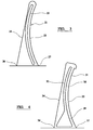
- Exemplary embodiments of the invention will now be described in greater detail with reference to the drawings in which
- Fig. 1 shows a first profile of a platform screen door system;
- Fig. 2 shows a second profile of a platform screen door system;
- Fig. 3 shows a third profile of a platform screen door system;
- Fig. 4 shows a fourth profile of a platform screen door system;
- Fig. 5 shows a fifth profile of a platform screen door system;
- Fig. 6 shows a sixth profile of a platform screen door system.
- Figure 1 shows a profile of a platform screen door system comprising a barrier section 1 housing a
gate 2. The barrier section 1 comprises afirst wall 3, which in use will face the platform, thefirst wall 3 being slightly inclined to the vertical and asecond wall 4, which in use will face away from the platform towards the platform edge, which wall is inclined at a substantially greater angle to the vertical than thefirst wall 3. The twowalls curved cap 5. The effect of the different angles of the first and second walls is that the apex of thecap 5 is located closer to the vertical plane of thebottom edge 6 of thefirst wall 3 than to the verticalplane bottom edge 7 of thesecond wall 4. Thegate 2 is housed within the barrier section 1 and is mounted at an angle to the vertical substantially parallel to that of thesection wall 4 so that in the closed position the top of the door is substantially as far away from the vertical plane of the platform edge as the top of the barrier. The drive mechanism for the door can be housed in the base of the barrier section adjacent to the lower edge of thedoor 2. The barrier and door control passenger access to and from a train. - Figure 2 shows an alternative architecture to the system of Figure 1, again comprising a
barrier section 11 housing adoor 12. Thewall 14 facing theplatform edge 14 is in this case curved away from the platform edge and thedoor 12 shares a similar curved profile. Thewall 13 facing the platform comprises a steppedlower portion 15, which is generally curved in the opposite direction to thewall 13 and an uppercurved portion 16 which is curved in the opposite direction and is substantially concentric with thecurved wall 13. The steppedlower portion 15 enables the drive gear to be house within thebarrier section 11. - Figure 3 shows a further alternative architecture to figures 1 and 2 again comprising a
barrier section 21 housing adoor 22. In this case thewall 24 facing the platform edge is generally planar but angled to the vertical away from the platform edge such that the top of the barrier section is located spatially more distant from the vertical plane of the platform edge than thebottom edge 26 of thewall 24. Thewall 23 facing the platform is in this case curved such that thebottom edge 27 of thewall 24 is located further away from the vertical plane of the platform edge than the top of the barrier. Thedoor 22 is in this case curved so that it is substantially concentric with thecurved wall 23. In this embodiment the drive gear is located in the space between the lower edge of thedoor 22 and thebottom edge 26. - Figure 4 shows a further alternative architecture to that of figures 1 to 3 again comprising a
barrier section 31 housing adoor 32. As in figure 3, thewall 34 facing the platform edge is generally planar but angled to the vertical away from the platform edge such that the top of the barrier section is located spatially more distant from the vertical plane of the platform edge than thebottom edge 36 of thewall 34. Thewall 33 facing the platform is in this case curved such that thebottom edge 37 of thewall 34 is located further away from the vertical plane of the platform edge than the top of the barrier. The top part of thebarrier 31 is in this case lipped so that there is a small overhang over thewall 33. The door in figure 4 has a more complex profile than the doors of figures 1 to 3. The profile of the door side facing the platform is generally curved being again substantially concentric with the curve of thewall 33. The rear face of the door however has two parts to the profile. The upper part of theprofile 38 is generally curved and substantially concentric with the front face, whereas the lower part of theprofile 39 is generally angled away from the curve of door so as to form a generally triangular cross-section. - The embodiment of figure 5 comprises again a
barrier section 41 housing adoor 42. Thewall 44 which in use faces the platform edge is substantially vertical. The wall facing the platform in the installed position comprises a firstupper portion 45 which is substantially vertical and parallel to thewall 44 and alower portion 46, which is generally convex curved away from thewall 44 and towards the platform surface. The top of the barrier is curved in a similar manner to the barriers of figures 1 to 3. - The embodiment of figure 6 is substantially the same as the embodiment of figure 5, save that the top of the barrier is substantially the same as the top in figure 4. For both the embodiments of figures 5 and 6, the drive gear is located in the space between the door and the lower curved portion of the
wall 46. In each of the embodiments of figures 1 to 6, the distance between vertical planes transecting the fore and rearmost points of the barrier is greater than the distance between the first and second wall surfaces. - In use, it has been found that there are three general scenarios for passengers encroaching in the space beyond the upper edge of the gate. These are stretching out an arm over the barrier, leaning against the barrier and looking out over the barrier. As can be readily understood a passenger stretching out an arm over the barrier reaches the furthest point from the barrier and in tests, distances of 700mm are easily reached. For leaning against the fence, passengers typically encroach about 300mm over the barrier. However, for looking out over the barrier, the distances are less standardised as they depend on the height of the passenger and the height of the barrier. For a low barrier height of say 1100mm, distances of 600mm can be easily reached by taller passengers whereas for a 1300mm, perhaps only 300mm will be reached.
- The screen and door designs of figures 1 to 6 address this issue by having their upper edge further away from the platform edge than the bottom edge of the screen facing the platform edge. For a 1300mm door system, if the door and barrier are inclined at an angle of approximately 13° to the vertical, then a passenger leaning over the edge by 300mm does not encroach beyond the edge of the platform. In the designs of figures 2 to 6, the stepped portion or curved portion further forces passengers further away from the edge. Due to the comparatively small angle the advantages of the lower height door systems are maintained without increasing the risk of creating a claustrophobic effect on passengers but the safety problems inherent in the use of a lower height barrier are greatly reduced.
- The barrier and gate can be made from a variety of materials including aluminium extrusions or plastic materials. The barrier can be manufactured so that the respective first and second walls form part of a single structure or the walls can be made separately and joined together.
Claims (7)
- A barrier (1) for a railway platform, which platform has a surface and an edge, which barrier is adapted to co-operate with a door or gate (2) for controlling passenger access to and from a train, the barrier comprising a first wall surface (3) facing away from the platform edge and a second wall surface (4) facing the platform edge, a top edge connecting the first and second wall surfaces, wherein at least one of the first or second wall surfaces (3,4) is inclined or shaped at least in part away from the vertical such that, in the installed position, the distance between the vertical plane transecting the forward-most point (7) of the barrier and a second vertical plane transecting the rearmost point (6) of the barrier is greater than the distance between the first and second wall surfaces adjacent to the top edge.
- A barrier for a railway platform according to Claim 1, wherein the first and/or second wall surfaces are curved away from the platform edge.
- A barrier for a railway platform according to Claim 1 or Claim 2, wherein the spatial separation of the first and second walls at their respective bottom edges is sufficient that the barrier is adapted to house the drive mechanism for a sliding door.
- A barrier for a railway platform according to any one of Claims 1 to 3, wherein the barrier is adapted to receive a sliding door.
- A barrier for a railway platform according to any one of Claims 1 to 4, wherein the lower part of the first wall surface is angled away from the plane of the surface of the remaining part of the wall so as to keep passengers away from the platform edge.
- A barrier for a railway platform according to any one of Claims 1 to 5, wherein the barrier has a height between 1100 and 1500mm from the platform surface.
- A door for a barrier system for a railway platform, according to any one of claims 1 to 6 wherein the door in the installed position is curved away from the platform edge.
Priority Applications (1)
| Application Number | Priority Date | Filing Date | Title |
|---|---|---|---|
| PL05735906T PL1740433T3 (en) | 2004-04-16 | 2005-04-18 | Screen and screen door for a railway platform |
Applications Claiming Priority (2)
| Application Number | Priority Date | Filing Date | Title |
|---|---|---|---|
| GB0408555A GB2413133A (en) | 2004-04-16 | 2004-04-16 | Barrier and barrier door for a railway platform |
| PCT/GB2005/001477 WO2005100117A1 (en) | 2004-04-16 | 2005-04-18 | Screen and screen door for a railway platform |
Publications (2)
| Publication Number | Publication Date |
|---|---|
| EP1740433A1 EP1740433A1 (en) | 2007-01-10 |
| EP1740433B1 true EP1740433B1 (en) | 2008-01-23 |
Family
ID=32320973
Family Applications (1)
| Application Number | Title | Priority Date | Filing Date |
|---|---|---|---|
| EP05735906A Expired - Lifetime EP1740433B1 (en) | 2004-04-16 | 2005-04-18 | Screen and screen door for a railway platform |
Country Status (10)
| Country | Link |
|---|---|
| EP (1) | EP1740433B1 (en) |
| JP (1) | JP4677441B2 (en) |
| KR (1) | KR101169967B1 (en) |
| CN (1) | CN100418820C (en) |
| AT (1) | ATE384652T1 (en) |
| DE (1) | DE602005004526T2 (en) |
| DK (1) | DK1740433T3 (en) |
| GB (1) | GB2413133A (en) |
| PL (1) | PL1740433T3 (en) |
| WO (1) | WO2005100117A1 (en) |
Families Citing this family (11)
| Publication number | Priority date | Publication date | Assignee | Title |
|---|---|---|---|---|
| JP4871188B2 (en) * | 2007-03-30 | 2012-02-08 | 東日本旅客鉄道株式会社 | Vehicle entry / exit step and platform door device |
| JP4871206B2 (en) * | 2007-05-11 | 2012-02-08 | 東日本旅客鉄道株式会社 | Platform door equipment |
| JP5007150B2 (en) * | 2007-05-11 | 2012-08-22 | 東日本旅客鉄道株式会社 | Platform door equipment |
| JP5007149B2 (en) * | 2007-05-11 | 2012-08-22 | 東日本旅客鉄道株式会社 | Platform door equipment |
| JP5060210B2 (en) * | 2007-08-24 | 2012-10-31 | 東日本旅客鉄道株式会社 | Home door structure |
| JP5060209B2 (en) * | 2007-08-24 | 2012-10-31 | 東日本旅客鉄道株式会社 | Platform door equipment |
| WO2011058940A1 (en) * | 2009-11-12 | 2011-05-19 | 国立大学法人東京大学 | Automatic platform gate |
| JP5311313B2 (en) * | 2010-12-03 | 2013-10-09 | 国立大学法人 東京大学 | Entry / exit position variable type platform door associating device with train and platform position variable type platform door configuration determining apparatus |
| EP3455116A4 (en) | 2016-05-09 | 2020-01-08 | Tal Leizer | SAFETY SYSTEM LOCATED ON A TRAIN PLATFORM |
| JP2017132469A (en) * | 2017-04-27 | 2017-08-03 | 三菱電機株式会社 | Home door device |
| CN107248442A (en) * | 2017-07-28 | 2017-10-13 | 苏州金螳螂建筑装饰股份有限公司 | A kind of screen door in rail transit insulating part |
Family Cites Families (27)
| Publication number | Priority date | Publication date | Assignee | Title |
|---|---|---|---|---|
| GB1262476A (en) * | 1969-02-06 | 1972-02-02 | Pbi Procedes & Brevets Ind | Improvements to the construction of highway carriageways having safety shoulders |
| US3712589A (en) * | 1971-06-24 | 1973-01-23 | Olin Corp | Porous or foamed metal energy absorption device |
| US4632598A (en) * | 1985-07-15 | 1986-12-30 | Richards David B | Movable roadway barrier |
| DE3807441A1 (en) * | 1988-03-07 | 1989-09-28 | Thiele Zaunsysteme Gmbh | FENCE ELEMENT AND FENCE MADE OF IT |
| JP2787105B2 (en) * | 1989-01-13 | 1998-08-13 | 幸雄 魚住 | Door system for landings for rail vehicles |
| JPH0340103A (en) * | 1989-07-07 | 1991-02-20 | Toshiba Corp | Control device |
| US5295441A (en) * | 1991-07-31 | 1994-03-22 | Kawasaki Jukogyo Kabushiki Kaisha | Sliding door apparatus for platform |
| JPH06239225A (en) * | 1993-02-12 | 1994-08-30 | Nabco Ltd | Entrance door device |
| JP3578778B2 (en) * | 1993-02-12 | 2004-10-20 | 東日本旅客鉄道株式会社 | Mobile fence device for platform |
| JPH06239224A (en) * | 1993-02-12 | 1994-08-30 | Nabco Ltd | Entrance door device |
| US5836714A (en) * | 1994-07-20 | 1998-11-17 | Off The Wall Production, Inc. | Control barrier systems |
| GB2291636A (en) * | 1994-07-26 | 1996-01-31 | Westinghouse Brake & Signal | Vehicle gap bridge |
| FR2741092A1 (en) * | 1995-11-09 | 1997-05-16 | Boisson Gerard Fernand Marcel | Ergonomic safety barrier for persons and vehicles |
| US5669307A (en) * | 1996-02-01 | 1997-09-23 | Cichy; Gerald R. | Transportation vehicle having doors with doorsills at different levels |
| FR2746825A3 (en) * | 1996-03-29 | 1997-10-03 | Martinez Y Loureiro S L | Barrier module |
| DE19654444A1 (en) * | 1996-12-31 | 1998-07-02 | Oskar Baier | Barrier for blocking access to platform edges, traffic lanes etc. |
| JP3656490B2 (en) | 1999-04-19 | 2005-06-08 | 日産自動車株式会社 | Toroidal continuously variable transmission |
| JP3227143B2 (en) * | 1999-08-03 | 2001-11-12 | 川崎重工業株式会社 | Platform movable fence |
| GB2363402B (en) * | 2000-06-16 | 2004-09-01 | Victor Joseph Wigley | Improvements to fencing/reusable fencing |
| JP2002012147A (en) * | 2000-06-29 | 2002-01-15 | Toyo Electric Mfg Co Ltd | Boarding assistance device |
| GB2377949B (en) * | 2001-06-13 | 2005-07-20 | Poundfield Products Ltd | Apparatus and method for constructing a freestanding wall |
| CN1454803A (en) * | 2002-04-29 | 2003-11-12 | 孙国立 | Intelligent safety guardrail for platform |
| JP4353683B2 (en) * | 2002-07-31 | 2009-10-28 | 株式会社日立製作所 | Platform door control device |
| JP2004332298A (en) * | 2003-05-02 | 2004-11-25 | Kesao Kasai | Safety fence |
| JP4149878B2 (en) * | 2003-08-28 | 2008-09-17 | ナブテスコ株式会社 | Double sliding platform gate |
| JP2005112154A (en) * | 2003-10-08 | 2005-04-28 | Nabtesco Corp | Platform door equipment |
| JP4276926B2 (en) * | 2003-11-07 | 2009-06-10 | ナブテスコ株式会社 | Platform door equipment |
-
2004
- 2004-04-16 GB GB0408555A patent/GB2413133A/en not_active Withdrawn
-
2005
- 2005-04-18 JP JP2007507851A patent/JP4677441B2/en not_active Expired - Fee Related
- 2005-04-18 KR KR1020067024070A patent/KR101169967B1/en not_active Expired - Fee Related
- 2005-04-18 PL PL05735906T patent/PL1740433T3/en unknown
- 2005-04-18 CN CNB2005800194650A patent/CN100418820C/en not_active Expired - Fee Related
- 2005-04-18 WO PCT/GB2005/001477 patent/WO2005100117A1/en not_active Ceased
- 2005-04-18 DK DK05735906T patent/DK1740433T3/en active
- 2005-04-18 AT AT05735906T patent/ATE384652T1/en not_active IP Right Cessation
- 2005-04-18 EP EP05735906A patent/EP1740433B1/en not_active Expired - Lifetime
- 2005-04-18 DE DE602005004526T patent/DE602005004526T2/en not_active Expired - Lifetime
Also Published As
| Publication number | Publication date |
|---|---|
| WO2005100117A1 (en) | 2005-10-27 |
| EP1740433A1 (en) | 2007-01-10 |
| GB2413133A (en) | 2005-10-19 |
| DE602005004526D1 (en) | 2008-03-13 |
| GB0408555D0 (en) | 2004-05-19 |
| DK1740433T3 (en) | 2008-06-02 |
| CN100418820C (en) | 2008-09-17 |
| PL1740433T3 (en) | 2008-06-30 |
| ATE384652T1 (en) | 2008-02-15 |
| CN1968843A (en) | 2007-05-23 |
| JP4677441B2 (en) | 2011-04-27 |
| KR20070032654A (en) | 2007-03-22 |
| JP2007532400A (en) | 2007-11-15 |
| KR101169967B1 (en) | 2012-08-06 |
| DE602005004526T2 (en) | 2009-02-05 |
Similar Documents
| Publication | Publication Date | Title |
|---|---|---|
| EP2117901B1 (en) | Platform screen door | |
| US6360668B1 (en) | Adaptable platform door system | |
| EP2164738B1 (en) | Platform gate for train stations | |
| EP1740433A1 (en) | Screen and screen door for a railway platform | |
| US9266538B2 (en) | Platform door system, method for operating a platform door system and door frame for a platform door system | |
| GB2418221A (en) | Platform screen door system | |
| EP1996783B1 (en) | Platform screen door system | |
| EP3467248B1 (en) | A glass panel system | |
| US6286277B1 (en) | Sliding panel system having panels sliding along at least one slide rail arrangement | |
| GB2291034A (en) | Safety/Security Barrier | |
| WO2011048391A1 (en) | Platform screen door system | |
| EP4079993B1 (en) | Railway station roof with integrated passenger guidance system | |
| EP4286235B1 (en) | Platform door, system comprising the platform door and method of actuating the platform door | |
| US1074862A (en) | Car seat and door arrangement. | |
| WO2011150490A1 (en) | Safety gate system for a subway platform | |
| HK40074529A (en) | An adaptable railway station roof and integrated passenger guidance system thereof | |
| WO2016189339A1 (en) | Inclined and out-of-square at the top, overlapping sliding frame without fixed skylight | |
| JP2012224277A (en) | Platform gate device | |
| CN113129764A (en) | Platform door display system |
Legal Events
| Date | Code | Title | Description |
|---|---|---|---|
| PUAI | Public reference made under article 153(3) epc to a published international application that has entered the european phase |
Free format text: ORIGINAL CODE: 0009012 |
|
| 17P | Request for examination filed |
Effective date: 20061116 |
|
| AK | Designated contracting states |
Kind code of ref document: A1 Designated state(s): AT BE BG CH CY CZ DE DK EE ES FI FR GB GR HU IE IS IT LI LT LU MC NL PL PT RO SE SI SK TR |
|
| DAX | Request for extension of the european patent (deleted) | ||
| GRAP | Despatch of communication of intention to grant a patent |
Free format text: ORIGINAL CODE: EPIDOSNIGR1 |
|
| GRAS | Grant fee paid |
Free format text: ORIGINAL CODE: EPIDOSNIGR3 |
|
| GRAA | (expected) grant |
Free format text: ORIGINAL CODE: 0009210 |
|
| AK | Designated contracting states |
Kind code of ref document: B1 Designated state(s): AT BE BG CH CY CZ DE DK EE ES FI FR GB GR HU IE IS IT LI LT LU MC NL PL PT RO SE SI SK TR |
|
| REG | Reference to a national code |
Ref country code: GB Ref legal event code: FG4D |
|
| REG | Reference to a national code |
Ref country code: CH Ref legal event code: EP |
|
| REG | Reference to a national code |
Ref country code: IE Ref legal event code: FG4D |
|
| REF | Corresponds to: |
Ref document number: 602005004526 Country of ref document: DE Date of ref document: 20080313 Kind code of ref document: P |
|
| REG | Reference to a national code |
Ref country code: GR Ref legal event code: EP Ref document number: 20080401095 Country of ref document: GR |
|
| REG | Reference to a national code |
Ref country code: CH Ref legal event code: NV Representative=s name: E. BLUM UND CO.AG PATENT- UND MARKENANWAELTE VSP |
|
| REG | Reference to a national code |
Ref country code: DK Ref legal event code: T3 |
|
| REG | Reference to a national code |
Ref country code: PL Ref legal event code: T3 |
|
| NLV1 | Nl: lapsed or annulled due to failure to fulfill the requirements of art. 29p and 29m of the patents act | ||
| PG25 | Lapsed in a contracting state [announced via postgrant information from national office to epo] |
Ref country code: IS Free format text: LAPSE BECAUSE OF FAILURE TO SUBMIT A TRANSLATION OF THE DESCRIPTION OR TO PAY THE FEE WITHIN THE PRESCRIBED TIME-LIMIT Effective date: 20080523 Ref country code: ES Free format text: LAPSE BECAUSE OF FAILURE TO SUBMIT A TRANSLATION OF THE DESCRIPTION OR TO PAY THE FEE WITHIN THE PRESCRIBED TIME-LIMIT Effective date: 20080504 |
|
| PG25 | Lapsed in a contracting state [announced via postgrant information from national office to epo] |
Ref country code: AT Free format text: LAPSE BECAUSE OF FAILURE TO SUBMIT A TRANSLATION OF THE DESCRIPTION OR TO PAY THE FEE WITHIN THE PRESCRIBED TIME-LIMIT Effective date: 20080123 Ref country code: BG Free format text: LAPSE BECAUSE OF FAILURE TO SUBMIT A TRANSLATION OF THE DESCRIPTION OR TO PAY THE FEE WITHIN THE PRESCRIBED TIME-LIMIT Effective date: 20080423 |
|
| REG | Reference to a national code |
Ref country code: HU Ref legal event code: AG4A Ref document number: E003412 Country of ref document: HU |
|
| PG25 | Lapsed in a contracting state [announced via postgrant information from national office to epo] |
Ref country code: SI Free format text: LAPSE BECAUSE OF FAILURE TO SUBMIT A TRANSLATION OF THE DESCRIPTION OR TO PAY THE FEE WITHIN THE PRESCRIBED TIME-LIMIT Effective date: 20080123 Ref country code: PT Free format text: LAPSE BECAUSE OF FAILURE TO SUBMIT A TRANSLATION OF THE DESCRIPTION OR TO PAY THE FEE WITHIN THE PRESCRIBED TIME-LIMIT Effective date: 20080623 Ref country code: BE Free format text: LAPSE BECAUSE OF FAILURE TO SUBMIT A TRANSLATION OF THE DESCRIPTION OR TO PAY THE FEE WITHIN THE PRESCRIBED TIME-LIMIT Effective date: 20080123 |
|
| ET | Fr: translation filed | ||
| PG25 | Lapsed in a contracting state [announced via postgrant information from national office to epo] |
Ref country code: SE Free format text: LAPSE BECAUSE OF FAILURE TO SUBMIT A TRANSLATION OF THE DESCRIPTION OR TO PAY THE FEE WITHIN THE PRESCRIBED TIME-LIMIT Effective date: 20080423 Ref country code: SK Free format text: LAPSE BECAUSE OF FAILURE TO SUBMIT A TRANSLATION OF THE DESCRIPTION OR TO PAY THE FEE WITHIN THE PRESCRIBED TIME-LIMIT Effective date: 20080123 Ref country code: NL Free format text: LAPSE BECAUSE OF FAILURE TO SUBMIT A TRANSLATION OF THE DESCRIPTION OR TO PAY THE FEE WITHIN THE PRESCRIBED TIME-LIMIT Effective date: 20080123 Ref country code: CZ Free format text: LAPSE BECAUSE OF FAILURE TO SUBMIT A TRANSLATION OF THE DESCRIPTION OR TO PAY THE FEE WITHIN THE PRESCRIBED TIME-LIMIT Effective date: 20080123 |
|
| PG25 | Lapsed in a contracting state [announced via postgrant information from national office to epo] |
Ref country code: MC Free format text: LAPSE BECAUSE OF NON-PAYMENT OF DUE FEES Effective date: 20080430 Ref country code: RO Free format text: LAPSE BECAUSE OF FAILURE TO SUBMIT A TRANSLATION OF THE DESCRIPTION OR TO PAY THE FEE WITHIN THE PRESCRIBED TIME-LIMIT Effective date: 20080123 |
|
| PLBE | No opposition filed within time limit |
Free format text: ORIGINAL CODE: 0009261 |
|
| STAA | Information on the status of an ep patent application or granted ep patent |
Free format text: STATUS: NO OPPOSITION FILED WITHIN TIME LIMIT |
|
| 26N | No opposition filed |
Effective date: 20081024 |
|
| PG25 | Lapsed in a contracting state [announced via postgrant information from national office to epo] |
Ref country code: LT Free format text: LAPSE BECAUSE OF FAILURE TO SUBMIT A TRANSLATION OF THE DESCRIPTION OR TO PAY THE FEE WITHIN THE PRESCRIBED TIME-LIMIT Effective date: 20080123 Ref country code: EE Free format text: LAPSE BECAUSE OF FAILURE TO SUBMIT A TRANSLATION OF THE DESCRIPTION OR TO PAY THE FEE WITHIN THE PRESCRIBED TIME-LIMIT Effective date: 20080123 |
|
| PG25 | Lapsed in a contracting state [announced via postgrant information from national office to epo] |
Ref country code: IE Free format text: LAPSE BECAUSE OF NON-PAYMENT OF DUE FEES Effective date: 20080418 |
|
| PG25 | Lapsed in a contracting state [announced via postgrant information from national office to epo] |
Ref country code: CY Free format text: LAPSE BECAUSE OF FAILURE TO SUBMIT A TRANSLATION OF THE DESCRIPTION OR TO PAY THE FEE WITHIN THE PRESCRIBED TIME-LIMIT Effective date: 20080123 |
|
| PG25 | Lapsed in a contracting state [announced via postgrant information from national office to epo] |
Ref country code: LU Free format text: LAPSE BECAUSE OF NON-PAYMENT OF DUE FEES Effective date: 20080418 |
|
| PGFP | Annual fee paid to national office [announced via postgrant information from national office to epo] |
Ref country code: HU Payment date: 20120417 Year of fee payment: 8 Ref country code: DK Payment date: 20120411 Year of fee payment: 8 Ref country code: TR Payment date: 20120417 Year of fee payment: 8 |
|
| PGFP | Annual fee paid to national office [announced via postgrant information from national office to epo] |
Ref country code: FI Payment date: 20120419 Year of fee payment: 8 Ref country code: PL Payment date: 20120417 Year of fee payment: 8 Ref country code: GR Payment date: 20120420 Year of fee payment: 8 |
|
| PGFP | Annual fee paid to national office [announced via postgrant information from national office to epo] |
Ref country code: IT Payment date: 20120420 Year of fee payment: 8 |
|
| REG | Reference to a national code |
Ref country code: DK Ref legal event code: EBP Effective date: 20130430 |
|
| REG | Reference to a national code |
Ref country code: GR Ref legal event code: ML Ref document number: 20080401095 Country of ref document: GR Effective date: 20131104 |
|
| PG25 | Lapsed in a contracting state [announced via postgrant information from national office to epo] |
Ref country code: GR Free format text: LAPSE BECAUSE OF NON-PAYMENT OF DUE FEES Effective date: 20131104 Ref country code: HU Free format text: LAPSE BECAUSE OF NON-PAYMENT OF DUE FEES Effective date: 20130419 Ref country code: FI Free format text: LAPSE BECAUSE OF NON-PAYMENT OF DUE FEES Effective date: 20130418 Ref country code: IT Free format text: LAPSE BECAUSE OF NON-PAYMENT OF DUE FEES Effective date: 20130418 |
|
| PG25 | Lapsed in a contracting state [announced via postgrant information from national office to epo] |
Ref country code: DK Free format text: LAPSE BECAUSE OF NON-PAYMENT OF DUE FEES Effective date: 20130430 |
|
| REG | Reference to a national code |
Ref country code: PL Ref legal event code: LAPE |
|
| PG25 | Lapsed in a contracting state [announced via postgrant information from national office to epo] |
Ref country code: PL Free format text: LAPSE BECAUSE OF NON-PAYMENT OF DUE FEES Effective date: 20130418 |
|
| PG25 | Lapsed in a contracting state [announced via postgrant information from national office to epo] |
Ref country code: TR Free format text: LAPSE BECAUSE OF NON-PAYMENT OF DUE FEES Effective date: 20130418 |
|
| REG | Reference to a national code |
Ref country code: FR Ref legal event code: PLFP Year of fee payment: 12 |
|
| REG | Reference to a national code |
Ref country code: FR Ref legal event code: PLFP Year of fee payment: 13 |
|
| REG | Reference to a national code |
Ref country code: FR Ref legal event code: PLFP Year of fee payment: 14 |
|
| PGFP | Annual fee paid to national office [announced via postgrant information from national office to epo] |
Ref country code: GB Payment date: 20230310 Year of fee payment: 19 |
|
| P01 | Opt-out of the competence of the unified patent court (upc) registered |
Effective date: 20230530 |
|
| PGFP | Annual fee paid to national office [announced via postgrant information from national office to epo] |
Ref country code: FR Payment date: 20230426 Year of fee payment: 19 Ref country code: CH Payment date: 20230502 Year of fee payment: 19 |
|
| PGFP | Annual fee paid to national office [announced via postgrant information from national office to epo] |
Ref country code: DE Payment date: 20240430 Year of fee payment: 20 |
|
| REG | Reference to a national code |
Ref country code: CH Ref legal event code: PL |
|
| GBPC | Gb: european patent ceased through non-payment of renewal fee |
Effective date: 20240418 |
|
| PG25 | Lapsed in a contracting state [announced via postgrant information from national office to epo] |
Ref country code: GB Free format text: LAPSE BECAUSE OF NON-PAYMENT OF DUE FEES Effective date: 20240418 |
|
| PG25 | Lapsed in a contracting state [announced via postgrant information from national office to epo] |
Ref country code: FR Free format text: LAPSE BECAUSE OF NON-PAYMENT OF DUE FEES Effective date: 20240430 |
|
| PG25 | Lapsed in a contracting state [announced via postgrant information from national office to epo] |
Ref country code: GB Free format text: LAPSE BECAUSE OF NON-PAYMENT OF DUE FEES Effective date: 20240418 Ref country code: FR Free format text: LAPSE BECAUSE OF NON-PAYMENT OF DUE FEES Effective date: 20240430 Ref country code: CH Free format text: LAPSE BECAUSE OF NON-PAYMENT OF DUE FEES Effective date: 20240430 |
|
| REG | Reference to a national code |
Ref country code: DE Ref legal event code: R071 Ref document number: 602005004526 Country of ref document: DE |