EP1739998B1 - Gerät und Verfahren zur Qualitätsprüfung eines batteriebetriebenen Mobiltelefons - Google Patents
Gerät und Verfahren zur Qualitätsprüfung eines batteriebetriebenen Mobiltelefons Download PDFInfo
- Publication number
- EP1739998B1 EP1739998B1 EP20050014048 EP05014048A EP1739998B1 EP 1739998 B1 EP1739998 B1 EP 1739998B1 EP 20050014048 EP20050014048 EP 20050014048 EP 05014048 A EP05014048 A EP 05014048A EP 1739998 B1 EP1739998 B1 EP 1739998B1
- Authority
- EP
- European Patent Office
- Prior art keywords
- phone
- unit
- switch
- contact assembly
- battery
- Prior art date
- Legal status (The legal status is an assumption and is not a legal conclusion. Google has not performed a legal analysis and makes no representation as to the accuracy of the status listed.)
- Expired - Lifetime
Links
Images



Classifications
-
- H—ELECTRICITY
- H04—ELECTRIC COMMUNICATION TECHNIQUE
- H04W—WIRELESS COMMUNICATION NETWORKS
- H04W24/00—Supervisory, monitoring or testing arrangements
Definitions
- the invention relates to a device as well as to a method for quality testing using a battery operated mobile phone.
- a mobile phone is conventionally placed in a suitable test device and brought into different locations within the network. At each location, the quality of communication is tested and logged. Similar test devices can also be used to test the quality of a mobile phone.
- the phone While in the test device, the phone is typically powered by a "dummy battery", which replaces the normal battery unit of the phone and is connected to an external power source.
- the "dummy battery” simulates the behavior of the phone's normal battery unit. This allows to interrupt the power supply to the phone in order to reset it in case of malfunction. This scheme becomes, however, more and more difficult because modern battery units are complex and therefore difficult to simulate.
- the problem to be solved by the present invention is to provide a method and device that allows to keep the phones powered while avoiding this issue at least partially.
- the phone's battery unit is connected to the phone unit via a switch unit.
- the switch unit comprises one or more switches, which allow to interrupt the connection between the battery unit and the phone unit if required.
- the phone unit can detect the presence of its regular battery unit and works correctly. For resetting the phone, the switch can be interrupted.
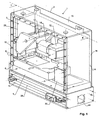
- Figs. 1 - 3 show a device 1 for testing mobile phones and their reception in a mobile phone network.
- the device comprises a housing 2 divided into an upper housing section 3 and a lower housing section 4.
- a phone holder 6 is arranged in upper housing section 3. In the present embodiment, it is formed by a frame-like structure surrounding a central opening or recess 7 shaped to receive a phone 8 in a well defined position and orientation.
- Phone holder 6 is a modular part that can be replaced easily. Differently shaped phone holders 6 can be provided for different types and brands of phones.
- Phone holder 6 is mounted on a frame structure 9 in the bottom part of upper housing section 3.
- the mobile phone 8 shown in Fig. 1 is a device with an integrated display 10. It is placed in phone holder 6 in such a way that display 10 is facing upwards.
- a camera 12 can be arranged in upper housing section 3.
- Camera 12 is mounted to a mount formed by two vertical plates 14 resting on frame structure 9, one of which is indicated in dashed lines in Fig. 1 , with the other being parallel thereto arranged at the opposite side of the device.
- the vertical plates 14 are connected to a top wall plate 15 of upper housing section 3, which in turn is connected to four vertical wall plates 16, thereby forming a rigid structure for keeping the relative position between camera 12 and display 10 fixed even when the device is exposed to movements, e.g. while it is being driven or walked through a mobile phone network.
- Imaging optics comprising a mirror 17 and a camera objective 18 project the light from display 10 onto the photo-sensitive array of camera 12, which allows to view the image or video data displayed on display 10 by means of the camera.
- mirror 17 is arranged under an angle of approximately 45°, such as between 30° and 60°, in respect to the surface of display 10. It reflects the light coming from display 10 into the direction of the axis 21 of camera 12. Camera axis 21 is substantially parallel to the surface of display 10 and to the longitudinal axis of mobile phone 8.
- mirror 17 folds the projection path of the imaging optics, thereby allowing to create a more compact device that takes less space and is mechanically more stable.
- a second advantage of using a design with folded projection path is the fact that, by removing mirror 17, it becomes possible to use the same basic design for testing a phone with hinged display, such as it is shown in Fig. 4 .
- the device of Fig. 4 is being used for a phone the display 10 of which is in a separate display housing 24 pivotally attached to the body of phone 8.
- display housing 24 is pivoted such that display 10 is substantially vertical and stands perpendicularly to camera axis 21.
- a retainer 25 e.g. mounted to vertical plate 14 is used to keep display housing 24 in its vertical position.
- FIGs. 1 - 3 it can be seen that there is a number of objects arranged in upper housing section 3, all of which can potentially reflect the diffuse light coming from display 10. To avoid undesired noise from such reflected light in the signal of camera 12, all components within upper housing sections 3 with the exception of the imaging optics 17, 18 and the mobile phone 8 should have black, non-reflecting surfaces. This is in particular true for the walls 15, 16 and the vertical plates 14.
- upper housing section 3 has a number of ventilation openings 28 in one of the vertical walls 16. These ventilation openings carry off heat generated by the device 1 and the phone 8.
- at least one light baffle plate 29 is arranged in front of the openings 28 for forming a labyrinth preventing light from entering upper housing section 3.
- Baffle plate 29 is non-transparent plastic or metal plate.
- several baffle plates can be arranged behind each other, forming a meandering path for passage of the ventilation air between them.
- SIM card holder 30 externally to phone 8 is arranged in upper housing section 3.
- a connector 31, as shown in Fig. 3 is provided to connect SIM card holder 30 to a dummy SIM card placed in the SIM card bay of phone 8, thereby connecting a SIM in SIM card holder 30 to phone 8. This makes it possible to replace the SIM card without removing phone 8 from phone holder 6.
- Upper housing section 3, and in particular the walls 15, 16 as well as the vertical plates 14, can be made of a plastic or metal. If they are of a conductive material, they may hinder radiowave communication between phone 8 and a mobile phone network.
- upper housing section 3 is therefore, in one embodiment, at least partially of plastics for allowing radiowave communication between phone 8 in holder 6 and the mobile phone network.
- the walls 15, 16 as well as the vertical plates 14 are, in that case, advantageously made from a sturdy plastic material.
- a lead-through 38 may be provided for connecting phone 8 in phone holder 6 to an external antenna.
- the signals from camera 12 must be processed by suitable control and processing circuitry.
- This circuitry is preferably integrated, at least in part, in device 1.
- control and processing circuitry 39 In the embodiment of Figs. 1 - 3 , most parts of the control and processing circuitry 39 are located on a PCB in lower housing section 4. In an advantageous embodiment, the control and processing circuitry 39 forms an image processing computer for evaluating the quality of the image or video from camera 12 connected to it.
- Control and processing circuitry 39 further comprises electronic components and software for controlling and monitoring the operation of phone 8.
- it is connected to a digital interface of the phone, which allows the circuitry to issue commands to the phone and to receive status information therefrom. It may also contain an interface to an audio output of phone 8.
- RF noise designates any electromagnetic noise in a frequency range above 1 MHz and in particular in the frequency range of communication that mobile phone networks are using.
- RF shielding 42 can e.g. consist of a metallic net or punctured plate, which has openings for the passage of electric cables and ventilation air.
- An air inlet opening 44 is arranged in lower housing section 4, connecting the same to the surroundings of device 1.
- a ventilator 45 and heater 46 are arranged at air inlet opening 44 for drawing in air and, if necessary and as described below, for heating the same.
- ventilator 45 The air drawn in by ventilator 45 through heater 46, through lower housing section 4, where it carries off heat generated by control and processing circuitry 39, and then enters upper housing section 3, where it carries off heat generated by phone 8 and camera 21. It then passes the gap above light baffle plate 29 and exits through the outlet openings 28.
- a temperature sensor 48 is arranged in upper housing section 3. The temperature from temperature sensor 48 is monitored by control and processing circuitry 39 and heater 46 is switched on if the temperature in upper housing section 3 is below a preferred operating temperature of phone 8, e.g. at 20 °C.
- a preferred operating temperature of phone 8 e.g. at 20 °C.
- the advantage of this is two-fold: One the one hand, phone 8 and in particular its display 10 may fail if temperatures are too low. On the other hand, heating the incoming air reduces its relative humidity, thereby reducing the risk of water condensation on display 10 of phone 8, on imaging optics 17, 18, and/or on camera 12.
- control and processing circuitry 39 for analyzing the quality of the incoming image or video signal depend on if a "full reference”, “reduced reference” or “no reference” analysis is to be carried out, i.e. if the original image or video (before it was transmitted over the network) is known fully, in part or not at all.
- Various such algorithms are known to the person skilled in the art and e.g. described in
- the resolution of camera 12 is advantageously sufficiently high such that each pixel of the projected part of display 10 is projected onto at least two horizontal and two vertical pixels of camera 12. This oversampling prevents data loss between display 10 and the signal of camera 12.
- some parts of the recorded image may have to be filtered out before processing. For example, if the projected part of display 10 contains status information superimposing a video image, the areas containing the status information may have to be ignored.
- control and processing circuitry 39 may also derive information indicative of an operational status of phone 8 from the signal from camera 12. For example, if phone 8 displays a typical error message on display 10 in case of malfunction, this error message can be detected by suitably processing the image recorded by camera 12. Similarly, a malfunctioning camera may exhibit typical display behavior, such as a complete freeze or blackout of the display, which again can be detected by suitably processing the signal from camera 12. Generally, the signal from the camera 12 can be processed to detect an operational status and in particular a malfunctioning of the phone. Depending on the detected operational status, suitable commands can then be issued to the phone or the phone can be reset.
- control and processing circuitry 39 is capable to fully process the signal from camera 12 and to create the relevant parameter's describing the quality of the image or video data. However, part of that functionality can also be delegated to an external computer.
- processing circuitry 39 has used the signal from camera 12 as one source of information for assessing the transmission quality.
- processing circuitry 39 can also use the phone's audio signal, or a digital raw data signal obtained through the phone's digital interface.
- Normal mobile phones consist of a phone unit and a battery unit.
- the phone unit incorporates most the phone's circuitry, its keys and its display.
- the battery unit contains a rechargeable battery and can be mounted to the phone unit to form the phone.
- the phone unit has a phone contact assembly, comprising a number of contacts arranged at a predefined position and geometry in a battery bay of the phone unit.
- the battery unit has a matching battery contact assembly, and the two contact assemblies are designed to contact each other for providing a power supply from the battery unit to the phone. In most phones, they also provide a means for charging the battery unit with current from an external power supplied plugged into the phone unit.
- the battery unit is removed from the phone unit, and a power supply is attached directly to the phone contact assembly.
- the power supply is designed to simulate the behavior and properties of the phone's original battery unit such that the phone is operating correctly.
- Modern battery units tend, though, to become more and more complex. This makes it difficult to design a power supply that properly simulates a battery unit.
- a switch unit 64 is arranged in the electrical path between battery unit 60 and phone unit 62.
- Switch unit 64 comprises a first switch contact assembly for being connected to the battery contact assembly, and a second switch contact assembly for being connected to the phone contact assembly. It further comprises at least one switch 66 for switching on and off a power supply from battery unit 60 to phone unit 62.
- control unit 39a which is formed by the processing and control circuitry 39.
- a power supply 67 is provided, which feeds power to a power supply plug 69, the latter being connected to a power supply input of phone unit 62.
- switch 66 is deactivated to interrupt the current.
- power supply 67 is switched off as well, which leaves phone 8 without current.
- FIG. 7 shows, for illustration purposes, the phone with the battery unit 60 removed from its bay 70
- Fig. 8 shows the phone with the battery unit 60 inserted into its bay 70, as it will be operated in the device of Figs. 1 - 3 .
- switch unit 64 comprises a carrier 72, which e.g. a flexible, nonconducting foil.
- Carrier 72 carries the first switch contact assembly 74 on its first side and the second switch contact assembly 76 on its second side.
- the first switch contact assembly 74 is shaped to contact the contacts of the battery contact assembly 78, while the second switch contact assembly 76 is shaped to contact the contacts of the phone contact assembly 80.
- a flexible wire or printed circuit foil forms a connector line 68 that connects the contacts on carrier 72 to switch or switches 66.
- the thickness of carrier 72 is less than 1 mm, in particular less than 500 ⁇ m, such that it is easily possible to insert battery unit 60 into bay 70 with carrier 72 being physically arranged between battery contact assembly 78 and phone contact assembly 80.
- all contacts are fed through switch unit 64, even only one of them is fed through an actual switch.
- the contacts that do not have to be fed through a switch can be connected directly to each other, without having to go through switch unit 64 at all. In that case, it is e.g. possible to reduce the size of carrier 76, such that it extends only over the contacts that need to be routed through a switch.
- a carrier 76 extending over all contacts of the contact assemblies is advantageous.
- the phone is operated while battery unit 60 resides in the battery bay of phone unit 62. It is, however, also possible to mount battery unit 60 at a distance from phone unit 62, in which case switch unit 64 comprises suitable wires or leads for carrying the currents between battery contact assembly 78 and phone contact assembly 80.
- FIG. 7 and 8 imply that the contact assemblies of switching unit 64 merely touch the contact assemblies of battery unit 60 and phone unit 62, it is also possible to solder or clamp the switch contact assemblies to the battery and/or phone contact assembly.
Landscapes
- Engineering & Computer Science (AREA)
- Computer Networks & Wireless Communication (AREA)
- Signal Processing (AREA)
- Telephone Set Structure (AREA)
- Mobile Radio Communication Systems (AREA)
- Charge And Discharge Circuits For Batteries Or The Like (AREA)
- Secondary Cells (AREA)
Claims (10)
- Ein Verfahren zur Beurteilung der Qualität eines Mobiltelefons und/oder Mobiltelefonnetzwerks umfassend die Schritten
Erhalten einer Telefoneinheit (62) und einer Batterieeinheit (60), wobei die genannte Batterieeinheit (60) geeignet ist, an die genannte Telefoneinheit (62) montiert zu werden und die genannte Telefoneinheit (62) mit Energie zu versorgen, um ein Mobiltelefon zusammenzusetzen und
Montieren der genannten Telefoneinheit (62) in einer Prüfvorrichtung, wobei die Prüfvorrichtung eine Steuereinheit (39a) zur Steuerung des Betriebs der Telefoneinheit (62) umfasst,
gekennzeichnet durch die Schritte
Verbinden der genannten Batterieeinheit (60) mit der genannten Telefoneinheit (62) über eine Schalteinheit (64), wobei die Schalteinheit (64) zumindest einen Schalter (66) zum Zuschalten oder Ausschalten einer Energieversorgung von der genannten Batterieeinheit (60) zu der genannten Telefoneinheit (62) und
Steuern der genannten Schalteinheit (64) von der genannten Steuereinheit (39a). - Das Verfahren von Anspruch 1, wobei die genannte Telefoneinheit (62) eine Telefonkontaktanordnung (80) und die genannte Batterieeinheit (60) eine Batteriekontaktanordnung hat, wobei die genannte Telefonkontaktanordnung (80) und die genannten Batteriekontaktanordnung (78) ausgestaltet sind, um einander zu kontaktieren, um eine Energieversorgung von der genannten Batterieeinheit (60) zu der genannten Telefoneinheit (62) bereitzustellen, und wobei die genannte Schalteinheit (64) eine erste Schaltkontaktanordnung (74) und eine zweite Schaltkontaktanordnung (76) hat, wobei die genannte erste Schaltkontaktanordnung mit der genannten Batteriekontaktanordnung (78) verbunden ist und die genannte zweite Schaltkontaktanordnung (76) mit der genannten Telefonkontaktanordnung (80) verbunden ist.
- Das Verfahren von Anspruch 2, wobei die genannte Schalteinheit (64) einen Träger (72) umfasst, der die genannte erste Schaltkontaktanordnung (74) auf einer ersten Seite davon trägt und die genannte zweite Schaltkontaktanordnung (76) auf einer zweiten Seite davon trägt, wobei der genannte Träger (72) physikalisch zwischen der genannten Telefonkontaktanordnung (80) und der genannten Batteriekontaktanordnung (78) angeordnet ist.
- Das Verfahren von einem der vorgehenden Ansprüche, weiter umfassend den Schritt, Energie einem Energieversorgungseingang der genannten Telefoneinheit (62) zuzuführen, um die genannte Telefoneinheit (62) zu versorgen und die genannte Batterieeinheit (60) zu laden.
- Eine Vorrichtung zur Beurteilung der Qualität eines Mobiltelefons und/oder Mobiltelefonnetzwerks umfassend eine Steuereinheit (39a) zum Steuern des Betriebs eines batteriebetriebenen Prüftelefons, wobei das genannte Prüftelefon eine Telefoneinheit (62) und eine Batterieeinheit (60) umfasst, dadurch gekennzeichnet dass, die genannte Vorrichtung weiter eine Schalteinheit (64) umfasst, um elektrisch zwischen der Batterieeinheit (60) und der Telefoneinheit (62) angeordnet zu sein, wobei die genannte Schalteinheit (64) eine erste Schaltkontaktanordnung (74), die geeignet ist zum Kontaktieren einer Batteriekontaktanordnung (78) der genannten Batterieeinheit (60), und eine zweite Schaltkontaktanordnung (76), die geeignet ist zum Kontaktieren einer Telefonkontaktanordnung (80) der genannten Telefoneinheit (62), umfasst, um die Batterieeinheit zu verbinden oder zu trennen von der Telefoneinheit.
- Die Vorrichtung von Anspruch 5, wobei die genannte Schalteinheit (64) einen Träger (72) umfasst, wobei die genannte erste Schaltkontaktanordnung (74) auf einer ersten Seite des genannten Trägers (72) angeordnet ist und die genannte zweite Schaltkontaktanordnung (76) auf einer zweiten Seite des genannten Trägers (72) angeordnet ist.
- Die Vorrichtung von Anspruch 6, wobei die genannten Schalteinheit (64) weiter zumindest einen Schalter (66) zum Ein- und Ausschalten einer Energieversorgung der genannten Batterieeinheit (60) zu der genannten Telefoneinheit (62) und eine Anschussleitung (68), die sich von dem genannten Träger (72) zu dem genannten Schalter (66) erstreckt, umfasst.
- Die Vorrichtung von einem der Ansprüche 6 oder 7, wobei der genannte Träger (72) eine Dicke von weniger als 1 mm hat.
- Die Vorrichtung von einem der Ansprüche 6 bis 8, wobei der Träger (72) flexible ist.
- Die Vorrichtung nach einem der Ansprüche 5 bis 9, weiter umfassend eine Energieversorgung (67) zum Zuführen von Strom zu einem Energieversorgungsanschluss (69) zum Einstecken in einen Energieversorgungseingang der genannten Telefoneinheit (62).
Priority Applications (6)
| Application Number | Priority Date | Filing Date | Title |
|---|---|---|---|
| ES05014048T ES2302099T3 (es) | 2005-06-29 | 2005-06-29 | Dispositivo y metodo para verificar la calidad de un telefono movil alimentado con bateria. |
| AT05014048T ATE388591T1 (de) | 2005-06-29 | 2005-06-29 | Gerät und verfahren zur qualitätsprüfung eines batteriebetriebenen mobiltelefons |
| DE200560005184 DE602005005184T2 (de) | 2005-06-29 | 2005-06-29 | Gerät und Verfahren zur Qualitätsprüfung eines batteriebetriebenen Mobiltelefons |
| EP20050014048 EP1739998B1 (de) | 2005-06-29 | 2005-06-29 | Gerät und Verfahren zur Qualitätsprüfung eines batteriebetriebenen Mobiltelefons |
| US11/916,534 US7957732B2 (en) | 2005-06-29 | 2006-06-13 | Device and method for quality testing using a battery operated mobile phone |
| PCT/CH2006/000317 WO2007000065A1 (en) | 2005-06-29 | 2006-06-13 | A device and method for quality testing using a battery operated mobile phone |
Applications Claiming Priority (1)
| Application Number | Priority Date | Filing Date | Title |
|---|---|---|---|
| EP20050014048 EP1739998B1 (de) | 2005-06-29 | 2005-06-29 | Gerät und Verfahren zur Qualitätsprüfung eines batteriebetriebenen Mobiltelefons |
Publications (2)
| Publication Number | Publication Date |
|---|---|
| EP1739998A1 EP1739998A1 (de) | 2007-01-03 |
| EP1739998B1 true EP1739998B1 (de) | 2008-03-05 |
Family
ID=35445985
Family Applications (1)
| Application Number | Title | Priority Date | Filing Date |
|---|---|---|---|
| EP20050014048 Expired - Lifetime EP1739998B1 (de) | 2005-06-29 | 2005-06-29 | Gerät und Verfahren zur Qualitätsprüfung eines batteriebetriebenen Mobiltelefons |
Country Status (6)
| Country | Link |
|---|---|
| US (1) | US7957732B2 (de) |
| EP (1) | EP1739998B1 (de) |
| AT (1) | ATE388591T1 (de) |
| DE (1) | DE602005005184T2 (de) |
| ES (1) | ES2302099T3 (de) |
| WO (1) | WO2007000065A1 (de) |
Cited By (1)
| Publication number | Priority date | Publication date | Assignee | Title |
|---|---|---|---|---|
| WO2015059553A1 (en) | 2013-10-24 | 2015-04-30 | Teleplan Technology B.V. | Method and apparatus for testing cell phones |
Families Citing this family (7)
| Publication number | Priority date | Publication date | Assignee | Title |
|---|---|---|---|---|
| US8055195B2 (en) * | 2007-12-31 | 2011-11-08 | Honeywell International Inc. | Cellular radio communicator and method for configuring the same |
| US8189052B1 (en) | 2008-07-29 | 2012-05-29 | Sprint Communications Company L.P. | Method and system for evaluating video processing technology |
| CN101877867A (zh) * | 2009-04-28 | 2010-11-03 | 深圳富泰宏精密工业有限公司 | 用于手机远程测试的服务器及方法 |
| US8799540B2 (en) * | 2010-01-05 | 2014-08-05 | Microsoft Corporation | Providing signals to electronic connectors |
| US9054534B2 (en) * | 2010-01-05 | 2015-06-09 | Microsoft Technology Licensing, Llc | Connectors for battery-powered devices |
| CN102413484A (zh) * | 2010-09-26 | 2012-04-11 | 西安龙飞软件有限公司 | 一种终端设备网络链接性能的测试系统和方法 |
| TW201245738A (en) * | 2011-05-12 | 2012-11-16 | Askey Computer Corp | Inspection apparatus using touch probe for signal transmission |
Family Cites Families (7)
| Publication number | Priority date | Publication date | Assignee | Title |
|---|---|---|---|---|
| JPH037435A (ja) * | 1989-06-05 | 1991-01-14 | Nec Corp | 無線選択呼出受信機 |
| US5389885A (en) * | 1992-01-27 | 1995-02-14 | Everett Charles Technologies, Inc. | Expandable diaphragm test modules and connectors |
| US5859481A (en) * | 1996-10-29 | 1999-01-12 | Ericsson Inc. | Auxiliary battery sensor switch |
| US5884195A (en) * | 1997-03-14 | 1999-03-16 | Andrew Corporation | Grounding assembly for programming cellular telephones |
| FI107841B (fi) * | 2000-03-15 | 2001-10-15 | Nokia Mobile Phones Ltd | Järjestelmä radiotaajuisen signaalin mittaamiseksi langattomassa viestimessä |
| US20040205154A1 (en) * | 2003-03-26 | 2004-10-14 | Lockheed Martin Corporation | System for integrated mobile devices |
| US20040207422A1 (en) * | 2003-04-11 | 2004-10-21 | Nokia Corporation | Aligning and testing system for communication device manufacturing |
-
2005
- 2005-06-29 AT AT05014048T patent/ATE388591T1/de not_active IP Right Cessation
- 2005-06-29 EP EP20050014048 patent/EP1739998B1/de not_active Expired - Lifetime
- 2005-06-29 ES ES05014048T patent/ES2302099T3/es not_active Expired - Lifetime
- 2005-06-29 DE DE200560005184 patent/DE602005005184T2/de not_active Expired - Lifetime
-
2006
- 2006-06-13 WO PCT/CH2006/000317 patent/WO2007000065A1/en not_active Ceased
- 2006-06-13 US US11/916,534 patent/US7957732B2/en not_active Expired - Fee Related
Cited By (2)
| Publication number | Priority date | Publication date | Assignee | Title |
|---|---|---|---|---|
| WO2015059553A1 (en) | 2013-10-24 | 2015-04-30 | Teleplan Technology B.V. | Method and apparatus for testing cell phones |
| WO2015059508A1 (en) | 2013-10-24 | 2015-04-30 | Teleplan Technology B.V. | Method and apparatus for testing cell phones |
Also Published As
| Publication number | Publication date |
|---|---|
| DE602005005184D1 (de) | 2008-04-17 |
| US20080200218A1 (en) | 2008-08-21 |
| DE602005005184T2 (de) | 2008-06-26 |
| ATE388591T1 (de) | 2008-03-15 |
| US7957732B2 (en) | 2011-06-07 |
| WO2007000065A1 (en) | 2007-01-04 |
| ES2302099T3 (es) | 2008-07-01 |
| EP1739998A1 (de) | 2007-01-03 |
Similar Documents
| Publication | Publication Date | Title |
|---|---|---|
| EP1739443A1 (de) | Gerät und Methode zur Beurteilung der Qualität eines Mobiltelefons oder Mobiltelefon-Netzwerks | |
| US11304519B2 (en) | Apparatus and method for simultaneously testing a plurality of mobile devices | |
| US20180198960A1 (en) | Device attachment with infrared imaging sensor | |
| KR20140021913A (ko) | 카메라 모듈 테스트 소켓 | |
| KR101471103B1 (ko) | 비전 기반의 가스절연개폐기 접지개폐기/단로기 구동부 위치인식 방법 | |
| EP1739998B1 (de) | Gerät und Verfahren zur Qualitätsprüfung eines batteriebetriebenen Mobiltelefons | |
| US8368805B2 (en) | User interface module for digital camera and digital camera including the same | |
| KR20160088152A (ko) | 이동 단말기의 rf성능 불량 테스트 회로 및 그 방법 | |
| CN109945976B (zh) | 双目成像检测装置及检测方法 | |
| KR20180101151A (ko) | 모듈 기반의 공정 유닛, 공정 유닛 제어 장치 및 방법 | |
| EP1739997B1 (de) | Gerät zur Qualitätsüberprüfung von verschiedenen Mobiltelefontypen | |
| CN110740255B (zh) | 调焦设备及方法 | |
| EP1739442B1 (de) | Kammer zur Bearbeitung elektronischer geräte | |
| US20120268152A1 (en) | Connection device for quality testing of charge-coupled device modules | |
| EP1575272A1 (de) | Duocam sowie Verfahren zu deren Montage | |
| KR102773958B1 (ko) | 화재징후 및 침입 감시를 위한 배전반 | |
| CN110544248A (zh) | 插槽检测方法及系统 | |
| CN111586370A (zh) | 一种公共区域ai视频检测图像捕捉设备 | |
| CN222940867U (zh) | 针对一体化超高清电视机的自动化拨测终端设备和系统 | |
| KR0148916B1 (ko) | 다기능 자동검사 조정시스템 | |
| CN119224444A (zh) | 测试系统、测试方法和电子设备 | |
| CN107426386A (zh) | 检测组件、无线装置及无线装置的测试方法 | |
| CN120161244A (zh) | 一种用于降低摄像模组阻抗测试复测率的方法及装置 | |
| CN120184627A (zh) | 连接器、功能模组及电子设备 | |
| JP2013197999A (ja) | 回路モジュールおよび電子情報機器 |
Legal Events
| Date | Code | Title | Description |
|---|---|---|---|
| PUAI | Public reference made under article 153(3) epc to a published international application that has entered the european phase |
Free format text: ORIGINAL CODE: 0009012 |
|
| AK | Designated contracting states |
Kind code of ref document: A1 Designated state(s): AT BE BG CH CY CZ DE DK EE ES FI FR GB GR HU IE IS IT LI LT LU MC NL PL PT RO SE SI SK TR |
|
| AX | Request for extension of the european patent |
Extension state: AL BA HR LV MK YU |
|
| 17P | Request for examination filed |
Effective date: 20070601 |
|
| RAP1 | Party data changed (applicant data changed or rights of an application transferred) |
Owner name: SPIRENT COMMUNICATIONS LICENSE AG |
|
| AKX | Designation fees paid |
Designated state(s): AT BE BG CH CY CZ DE DK EE ES FI FR GB GR HU IE IS IT LI LT LU MC NL PL PT RO SE SI SK TR |
|
| GRAP | Despatch of communication of intention to grant a patent |
Free format text: ORIGINAL CODE: EPIDOSNIGR1 |
|
| GRAS | Grant fee paid |
Free format text: ORIGINAL CODE: EPIDOSNIGR3 |
|
| GRAA | (expected) grant |
Free format text: ORIGINAL CODE: 0009210 |
|
| AK | Designated contracting states |
Kind code of ref document: B1 Designated state(s): AT BE BG CH CY CZ DE DK EE ES FI FR GB GR HU IE IS IT LI LT LU MC NL PL PT RO SE SI SK TR |
|
| REG | Reference to a national code |
Ref country code: GB Ref legal event code: FG4D |
|
| RAP2 | Party data changed (patent owner data changed or rights of a patent transferred) |
Owner name: SWISSQUAL LICENSE AG |
|
| REG | Reference to a national code |
Ref country code: CH Ref legal event code: NV Representative=s name: E. BLUM & CO. AG PATENT- UND MARKENANWAELTE VSP Ref country code: CH Ref legal event code: EP |
|
| REG | Reference to a national code |
Ref country code: IE Ref legal event code: FG4D |
|
| REF | Corresponds to: |
Ref document number: 602005005184 Country of ref document: DE Date of ref document: 20080417 Kind code of ref document: P |
|
| NLT2 | Nl: modifications (of names), taken from the european patent patent bulletin |
Owner name: SWISSQUAL LICENSE AG Effective date: 20080319 |
|
| REG | Reference to a national code |
Ref country code: ES Ref legal event code: FG2A Ref document number: 2302099 Country of ref document: ES Kind code of ref document: T3 |
|
| PG25 | Lapsed in a contracting state [announced via postgrant information from national office to epo] |
Ref country code: FI Free format text: LAPSE BECAUSE OF FAILURE TO SUBMIT A TRANSLATION OF THE DESCRIPTION OR TO PAY THE FEE WITHIN THE PRESCRIBED TIME-LIMIT Effective date: 20080305 |
|
| PG25 | Lapsed in a contracting state [announced via postgrant information from national office to epo] |
Ref country code: AT Free format text: LAPSE BECAUSE OF FAILURE TO SUBMIT A TRANSLATION OF THE DESCRIPTION OR TO PAY THE FEE WITHIN THE PRESCRIBED TIME-LIMIT Effective date: 20080305 |
|
| NLV1 | Nl: lapsed or annulled due to failure to fulfill the requirements of art. 29p and 29m of the patents act | ||
| PG25 | Lapsed in a contracting state [announced via postgrant information from national office to epo] |
Ref country code: BE Free format text: LAPSE BECAUSE OF FAILURE TO SUBMIT A TRANSLATION OF THE DESCRIPTION OR TO PAY THE FEE WITHIN THE PRESCRIBED TIME-LIMIT Effective date: 20080305 Ref country code: PL Free format text: LAPSE BECAUSE OF FAILURE TO SUBMIT A TRANSLATION OF THE DESCRIPTION OR TO PAY THE FEE WITHIN THE PRESCRIBED TIME-LIMIT Effective date: 20080305 Ref country code: SI Free format text: LAPSE BECAUSE OF FAILURE TO SUBMIT A TRANSLATION OF THE DESCRIPTION OR TO PAY THE FEE WITHIN THE PRESCRIBED TIME-LIMIT Effective date: 20080305 |
|
| PG25 | Lapsed in a contracting state [announced via postgrant information from national office to epo] |
Ref country code: NL Free format text: LAPSE BECAUSE OF FAILURE TO SUBMIT A TRANSLATION OF THE DESCRIPTION OR TO PAY THE FEE WITHIN THE PRESCRIBED TIME-LIMIT Effective date: 20080305 Ref country code: CZ Free format text: LAPSE BECAUSE OF FAILURE TO SUBMIT A TRANSLATION OF THE DESCRIPTION OR TO PAY THE FEE WITHIN THE PRESCRIBED TIME-LIMIT Effective date: 20080305 Ref country code: PT Free format text: LAPSE BECAUSE OF FAILURE TO SUBMIT A TRANSLATION OF THE DESCRIPTION OR TO PAY THE FEE WITHIN THE PRESCRIBED TIME-LIMIT Effective date: 20080805 Ref country code: SE Free format text: LAPSE BECAUSE OF FAILURE TO SUBMIT A TRANSLATION OF THE DESCRIPTION OR TO PAY THE FEE WITHIN THE PRESCRIBED TIME-LIMIT Effective date: 20080605 Ref country code: SK Free format text: LAPSE BECAUSE OF FAILURE TO SUBMIT A TRANSLATION OF THE DESCRIPTION OR TO PAY THE FEE WITHIN THE PRESCRIBED TIME-LIMIT Effective date: 20080305 |
|
| PG25 | Lapsed in a contracting state [announced via postgrant information from national office to epo] |
Ref country code: RO Free format text: LAPSE BECAUSE OF FAILURE TO SUBMIT A TRANSLATION OF THE DESCRIPTION OR TO PAY THE FEE WITHIN THE PRESCRIBED TIME-LIMIT Effective date: 20080305 |
|
| ET | Fr: translation filed | ||
| PG25 | Lapsed in a contracting state [announced via postgrant information from national office to epo] |
Ref country code: IS Free format text: LAPSE BECAUSE OF FAILURE TO SUBMIT A TRANSLATION OF THE DESCRIPTION OR TO PAY THE FEE WITHIN THE PRESCRIBED TIME-LIMIT Effective date: 20080705 |
|
| PLBE | No opposition filed within time limit |
Free format text: ORIGINAL CODE: 0009261 |
|
| STAA | Information on the status of an ep patent application or granted ep patent |
Free format text: STATUS: NO OPPOSITION FILED WITHIN TIME LIMIT |
|
| PG25 | Lapsed in a contracting state [announced via postgrant information from national office to epo] |
Ref country code: MC Free format text: LAPSE BECAUSE OF NON-PAYMENT OF DUE FEES Effective date: 20080630 Ref country code: DK Free format text: LAPSE BECAUSE OF FAILURE TO SUBMIT A TRANSLATION OF THE DESCRIPTION OR TO PAY THE FEE WITHIN THE PRESCRIBED TIME-LIMIT Effective date: 20080305 Ref country code: LT Free format text: LAPSE BECAUSE OF FAILURE TO SUBMIT A TRANSLATION OF THE DESCRIPTION OR TO PAY THE FEE WITHIN THE PRESCRIBED TIME-LIMIT Effective date: 20080305 |
|
| 26N | No opposition filed |
Effective date: 20081208 |
|
| REG | Reference to a national code |
Ref country code: CH Ref legal event code: PFA Owner name: SWISSQUAL LICENSE AG Free format text: SWISSQUAL LICENSE AG#BAARERSTRASSE 78#6300 ZUG (CH) -TRANSFER TO- SWISSQUAL LICENSE AG#ALLMENDWEG 8#4528 ZUCHWIL (CH) |
|
| PG25 | Lapsed in a contracting state [announced via postgrant information from national office to epo] |
Ref country code: EE Free format text: LAPSE BECAUSE OF FAILURE TO SUBMIT A TRANSLATION OF THE DESCRIPTION OR TO PAY THE FEE WITHIN THE PRESCRIBED TIME-LIMIT Effective date: 20080305 Ref country code: BG Free format text: LAPSE BECAUSE OF FAILURE TO SUBMIT A TRANSLATION OF THE DESCRIPTION OR TO PAY THE FEE WITHIN THE PRESCRIBED TIME-LIMIT Effective date: 20080605 Ref country code: IE Free format text: LAPSE BECAUSE OF NON-PAYMENT OF DUE FEES Effective date: 20080630 |
|
| PG25 | Lapsed in a contracting state [announced via postgrant information from national office to epo] |
Ref country code: CY Free format text: LAPSE BECAUSE OF FAILURE TO SUBMIT A TRANSLATION OF THE DESCRIPTION OR TO PAY THE FEE WITHIN THE PRESCRIBED TIME-LIMIT Effective date: 20080305 |
|
| REG | Reference to a national code |
Ref country code: FR Ref legal event code: CA |
|
| PG25 | Lapsed in a contracting state [announced via postgrant information from national office to epo] |
Ref country code: HU Free format text: LAPSE BECAUSE OF FAILURE TO SUBMIT A TRANSLATION OF THE DESCRIPTION OR TO PAY THE FEE WITHIN THE PRESCRIBED TIME-LIMIT Effective date: 20080906 Ref country code: LU Free format text: LAPSE BECAUSE OF NON-PAYMENT OF DUE FEES Effective date: 20080629 |
|
| PG25 | Lapsed in a contracting state [announced via postgrant information from national office to epo] |
Ref country code: TR Free format text: LAPSE BECAUSE OF FAILURE TO SUBMIT A TRANSLATION OF THE DESCRIPTION OR TO PAY THE FEE WITHIN THE PRESCRIBED TIME-LIMIT Effective date: 20080305 |
|
| PG25 | Lapsed in a contracting state [announced via postgrant information from national office to epo] |
Ref country code: GR Free format text: LAPSE BECAUSE OF FAILURE TO SUBMIT A TRANSLATION OF THE DESCRIPTION OR TO PAY THE FEE WITHIN THE PRESCRIBED TIME-LIMIT Effective date: 20080606 |
|
| REG | Reference to a national code |
Ref country code: FR Ref legal event code: PLFP Year of fee payment: 12 |
|
| PGFP | Annual fee paid to national office [announced via postgrant information from national office to epo] |
Ref country code: CH Payment date: 20160511 Year of fee payment: 12 Ref country code: GB Payment date: 20160621 Year of fee payment: 12 Ref country code: DE Payment date: 20160621 Year of fee payment: 12 Ref country code: ES Payment date: 20160614 Year of fee payment: 12 |
|
| PGFP | Annual fee paid to national office [announced via postgrant information from national office to epo] |
Ref country code: FR Payment date: 20160627 Year of fee payment: 12 |
|
| PGFP | Annual fee paid to national office [announced via postgrant information from national office to epo] |
Ref country code: IT Payment date: 20160628 Year of fee payment: 12 |
|
| REG | Reference to a national code |
Ref country code: DE Ref legal event code: R119 Ref document number: 602005005184 Country of ref document: DE |
|
| REG | Reference to a national code |
Ref country code: CH Ref legal event code: PL |
|
| GBPC | Gb: european patent ceased through non-payment of renewal fee |
Effective date: 20170629 |
|
| REG | Reference to a national code |
Ref country code: FR Ref legal event code: ST Effective date: 20180228 |
|
| PG25 | Lapsed in a contracting state [announced via postgrant information from national office to epo] |
Ref country code: GB Free format text: LAPSE BECAUSE OF NON-PAYMENT OF DUE FEES Effective date: 20170629 Ref country code: CH Free format text: LAPSE BECAUSE OF NON-PAYMENT OF DUE FEES Effective date: 20170630 Ref country code: DE Free format text: LAPSE BECAUSE OF NON-PAYMENT OF DUE FEES Effective date: 20180103 Ref country code: LI Free format text: LAPSE BECAUSE OF NON-PAYMENT OF DUE FEES Effective date: 20170630 |
|
| PG25 | Lapsed in a contracting state [announced via postgrant information from national office to epo] |
Ref country code: FR Free format text: LAPSE BECAUSE OF NON-PAYMENT OF DUE FEES Effective date: 20170630 Ref country code: IT Free format text: LAPSE BECAUSE OF NON-PAYMENT OF DUE FEES Effective date: 20170629 |
|
| REG | Reference to a national code |
Ref country code: ES Ref legal event code: FD2A Effective date: 20181107 |
|
| PG25 | Lapsed in a contracting state [announced via postgrant information from national office to epo] |
Ref country code: ES Free format text: LAPSE BECAUSE OF NON-PAYMENT OF DUE FEES Effective date: 20170630 |