EP1739812A2 - Linear motor and linear compressor using the same - Google Patents
Linear motor and linear compressor using the same Download PDFInfo
- Publication number
- EP1739812A2 EP1739812A2 EP05257358A EP05257358A EP1739812A2 EP 1739812 A2 EP1739812 A2 EP 1739812A2 EP 05257358 A EP05257358 A EP 05257358A EP 05257358 A EP05257358 A EP 05257358A EP 1739812 A2 EP1739812 A2 EP 1739812A2
- Authority
- EP
- European Patent Office
- Prior art keywords
- coil
- coils
- linear motor
- coil groups
- set forth
- Prior art date
- Legal status (The legal status is an assumption and is not a legal conclusion. Google has not performed a legal analysis and makes no representation as to the accuracy of the status listed.)
- Ceased
Links
Images


Classifications
-
- H—ELECTRICITY
- H02—GENERATION; CONVERSION OR DISTRIBUTION OF ELECTRIC POWER
- H02K—DYNAMO-ELECTRIC MACHINES
- H02K41/00—Propulsion systems in which a rigid body is moved along a path due to dynamo-electric interaction between the body and a magnetic field travelling along the path
- H02K41/02—Linear motors; Sectional motors
-
- F—MECHANICAL ENGINEERING; LIGHTING; HEATING; WEAPONS; BLASTING
- F04—POSITIVE - DISPLACEMENT MACHINES FOR LIQUIDS; PUMPS FOR LIQUIDS OR ELASTIC FLUIDS
- F04B—POSITIVE-DISPLACEMENT MACHINES FOR LIQUIDS; PUMPS
- F04B35/00—Piston pumps specially adapted for elastic fluids and characterised by the driving means to their working members, or by combination with, or adaptation to, specific driving engines or motors, not otherwise provided for
- F04B35/04—Piston pumps specially adapted for elastic fluids and characterised by the driving means to their working members, or by combination with, or adaptation to, specific driving engines or motors, not otherwise provided for the means being electric
- F04B35/045—Piston pumps specially adapted for elastic fluids and characterised by the driving means to their working members, or by combination with, or adaptation to, specific driving engines or motors, not otherwise provided for the means being electric using solenoids
-
- H—ELECTRICITY
- H02—GENERATION; CONVERSION OR DISTRIBUTION OF ELECTRIC POWER
- H02K—DYNAMO-ELECTRIC MACHINES
- H02K33/00—Motors with reciprocating, oscillating or vibrating magnet, armature or coil system
- H02K33/02—Motors with reciprocating, oscillating or vibrating magnet, armature or coil system with armatures moved one way by energisation of a single coil system and returned by mechanical force, e.g. by springs
- H02K33/04—Motors with reciprocating, oscillating or vibrating magnet, armature or coil system with armatures moved one way by energisation of a single coil system and returned by mechanical force, e.g. by springs wherein the frequency of operation is determined by the frequency of uninterrupted AC energisation
- H02K33/06—Motors with reciprocating, oscillating or vibrating magnet, armature or coil system with armatures moved one way by energisation of a single coil system and returned by mechanical force, e.g. by springs wherein the frequency of operation is determined by the frequency of uninterrupted AC energisation with polarised armatures
-
- H—ELECTRICITY
- H02—GENERATION; CONVERSION OR DISTRIBUTION OF ELECTRIC POWER
- H02P—CONTROL OR REGULATION OF ELECTRIC MOTORS, ELECTRIC GENERATORS OR DYNAMO-ELECTRIC CONVERTERS; CONTROLLING TRANSFORMERS, REACTORS OR CHOKE COILS
- H02P25/00—Arrangements or methods for the control of AC motors characterised by the kind of AC motor or by structural details
- H02P25/02—Arrangements or methods for the control of AC motors characterised by the kind of AC motor or by structural details characterised by the kind of motor
- H02P25/032—Reciprocating, oscillating or vibrating motors
Definitions
- the present invention relates to a linear motor and a linear compressor using the same. It particularly, relates to a linear motor and a linear compressor using the same wherein a plurality of coil groups, provided in the linear motor, are connected in series or in parallel, and driving power is applied to part or all of the coil groups depending on the magnitude of load current applied to the linear motor.
- Embodiments of the present invention can provide a linear motor which achieves an improved efficiency with a reduced size.
- a compressor is an apparatus to compress fluid, such as air or gaseous refrigerant.
- a linear compressor is designed to introduce, compress, and discharge gaseous refrigerant through a linear reciprocating movement of a piston in a cylinder, which is performed by a linear driving force of a linear motor.
- Known linear compressors comprises a hermetic container having a suction pipe that is connected to a certain location of the hermetic container to introduce refrigerant into the hermetic container, a cylinder mounted in the hermetic container and having a refrigerant compression chamber therein, a piston mounted to be linearly reciprocated in the cylinder and adapted to introduce the refrigerant into the compression chamber to thereby compress it therein, and a linear motor connected to an end of the piston to provide a driving force required to linearly reciprocate the piston.
- the linear motor includes a stator having a coil assembly, and a mover having a magnet and a magnet frame to connect the magnet to the piston.
- a known linear motor 1 includes a coil assembly 2 to produce a magnetic field when AC power is applied thereto, and a relay 5 to selectively transmit the AC power to the coil assembly 2.
- the linear motor 1 is designed to vary the magnitude of a magnetic field depending on a load applied thereto, thereby achieving improved motor efficiency.
- the coil assembly 2, provided in the linear motor 1, consists of a main coil Cm and an auxiliary coil Cs.
- the linear motor 1 operates in a power mode wherein the relay 5 is connected to a connecting terminal 3 of the main coil Cm to increase the magnitude of electric current flowing into the main coil Cm. This increases the strength of the resulting magnetic field, achieving a lengthened stoke of a piston.
- the linear motor 1 operates in a save mode wherein the relay 5 is connected to a connecting terminal 4 of the main coil Cm and the auxiliary coil Cs to decrease the magnitude of electric current flowing into both the main coil Cm and the auxiliary coil Cs. This decreases the strength of the resulting magnetic field, achieving a shortened stoke of the piston.
- FIG. 2 is a diagram illustrating the coil assembly of the known linear motor shown in figure 1.
- the coil assembly 2 includes a bobbin, and coils wound plural turns on the bobbin and adapted to produce a magnetic field when electric voltage is applied thereto.
- the coils include the main coil Cm immediately disposed on the bobbin, and the auxiliary coil Cs disposed around the main coil Cm.
- the main coil Cm and the auxiliary coil Cs are connected in series.
- the known linear motor configured and operated as stated above has a problem in that the size of the linear motor should be large to ensure successful operation of the liner motor in the low-load save mode.
- the coils are conductive wires, such as copper wires, they basically have a predetermined magnitude of resistance.
- the resistance of a conductive wire is proportional to the length of the wire and inversely proportional to the cross sectional area of the wire.
- the linear motor is configured in such a fashion that the conductive wires (hereinafter, referred to as coil conductors) of the main and auxiliary coils are closely wound on the bobbin to be stacked one above another.
- coil conductors the conductive wires (hereinafter, referred to as coil conductors) of the main and auxiliary coils are closely wound on the bobbin to be stacked one above another.
- cross sectional areas of the coil conductors increase, it is very difficult to wind the coils in the above manner.
- the present invention has been made in view of the above-mentioned problems.
- Embodiments of the present invention provide a linear motor and a linear compressor using the same, in which a plurality of coil groups, provided in the linear motor, are connected in series or in parallel, and driving power is applied to part or all of the coil groups depending on the magnitude of load current applied to the linear motor, whereby the linear motor achieves improved efficiency with a reduced size.
- Embodiments of the present invention also provide a linear motor and a linear compressor using the same, wherein a plurality of coil conductors are used to form coil groups of the linear motor, whereby a manufacturing process of the linear motor can be considerably simplified as compared to a known method of winding coil conductors each having a large cross sectional area on a bobbin.
- a linear motor comprising: a bobbin; a plurality of coil groups wound on the bobbin and connected to each other in series or in parallel to allow driving power to be applied to part or all of the coil groups; and a magnet adapted to be linearly reciprocated under the influence of a magnetic field that is produced by the coil groups depending on load current flowing through the coil groups.
- the coil groups may include first and second coil groups each consisting of one or more coils stacked one above another on the bobbin.
- the first and second coil groups may have first and second main coils immediately disposed on the bobbin, and first and second auxiliary coils disposed around the first and second main coils, the first and second main coils may be connected to each other in parallel, and the first and second main coils may be twisted together prior to being wound on the bobbin.
- a linear compressor comprising: a cylinder block having a cylinder; a back cover spaced apart from the cylinder block and having a refrigerant suction channel; an outer core disposed between the cylinder block and the back cover; a coil assembly mounted in the outer core and including a plurality of coil groups that are connected to each other in series or in parallel to allow driving power to be selectively applied thereto depending on the magnitude of load current; an inner core spaced apart from the outer core; a magnet located between the outer core and the inner core and adapted to be linearly reciprocated under the influence of a magnetic field that is produced by the coil assembly; a piston connected to the magnet to be linearly reciprocated in the cylinder and having a refrigerant passage formed therein; a suction valve mounted to the piston to open or close the refrigerant passage; and a discharge valve mounted to the cylinder block to open or close the cylinder.
- a plurality of coil conductors are wound to form a plurality of coil groups and the plurality of coil groups are connected in series or in parallel, so that the capacity (or impedance) of the coils is variable depending on a load applied to the linear motor. This effectively improves the efficiency of the linear motor. Also, using the coil conductors having a small cross sectional area enables reduction in the size of the linear motor.
- FIG. 3 is a circuit diagram of a linear motor.
- the linear motor comprises a power supply unit to apply AC power, supplied from an exterior source, to a linear motor body 50, the linear motor body 50 to perform a linear reciprocating movement upon receiving the AC power applied from the power supply unit, and a switch 90 connected between the linear motor body 50 and the power supply unit to apply the AC power from the power source to part or all of coils mounted in the linear motor body 50.
- the linear motor body 50 includes a stator (not shown) and a mover (not shown).
- the mover is connected at a certain location thereof to a fixing portion of a piston. Thereby, if the mover is linearly reciprocated under the influence of a magnetic field produced in the stator, the piston, connected to the mover, compresses a refrigerant while being linearly reciprocated in a cylinder.
- the stator of the linear motor body 50 includes an outer core in the form of a stack, an inner core in the form of a stack and inwardly spaced apart from the outer core, and a coil assembly mounted in the outer core.
- the coil assembly includes a plurality of coils adapted to produce a magnetic field when electric voltage is applied thereto.
- the mover includes a magnet located between the outer core and the inner core and connected to the piston.
- the plurality of coils of the coil assembly includes main coils Cm, and auxiliary coils Cs.
- the main coils Cm are connected in parallel, and the auxiliary coils Cs are connected in series.
- the coil assembly further includes a ground tap 81 connected at one end thereof to first ends of the respective main coils Cm connected in parallel, the other end of the ground tap 81 being connected to a ground end of the power supply unit, a first connecting tap 82 connected to second ends of the respective main coils Cm and a first end of the auxiliary coils Cs connected in series, and a second connecting tap 83 connected to a second end of the auxiliary coils Cs.
- the switch 90 is a device to allow the AC power of the power supply unit to be selectively applied to the coil assembly.
- the switch 90 is may be a relay, but the present invention is not limited thereto.
- the switch 90 When the switch 90 is connected to the first connecting tap 82, the AC power from the power supply unit is applied to the main coils Cm. Also, when the switch 90 is connected to the second connecting tap 83, the AC power is applied to the main coils Cm and the auxiliary coils Cs.
- FIG. 4 is a wiring diagram illustrating wiring of the coils provided in the linear motor.
- the coils of the coil assembly form a plurality of coil groups, which are formed by winding a plurality of coil conductors, respectively.
- the number of the coil groups is not limited to a specific number, for the convenience of explanation, the following description is based on the assumption that first and second coil groups are formed, each coil group being formed by winding two coil conductors.
- the first coil group 60 includes a first main coil 61 and a first auxiliary coil 62
- the second coil group 70 includes a second main coil 71 and a second auxiliary coil 72.
- the first and second main coils 61 and 71 are connected with the first and second auxiliary coils 62 and 72 in series.
- first and second main coils 61 and 71 are connected in parallel, while the first and second auxiliary coils 62 and 72 are connected in series.
- the ground tap 81 which is connected to the ground tap of the power supply unit, is connected to the first ends of the first and second main coils 61 and 71 connected in parallel.
- the first connecting tap 82 to which the AC power is applied, is provided between the main coils 61 and 71 and the auxiliary coils 62 and 72. When high load is applied to the linear motor or the linear compressor, the AC power is applied to the main coils 61 and 71 via the first connecting tap 82.
- the first and second auxiliary coils 62 and 72 are connected in series, so that the first and second connecting taps 82 and 83 are connected to opposite ends thereof.
- the AC power is applied to the entire coils via the second connecting tap 83 to thereby considerably reduce the magnitude of load current.
- FIG. 5 is a schematic diagram illustrating the coil assembly of a linear motor.
- FIG. 6 is a view illustrating the winding structure of the coils provided in the linear motor.
- the coil assembly includes a bobbin, and the first and second coil groups 60 and 70 wound on the bobbin.
- the first and second coil groups 60 and 70 are wound on the bobbin in parallel to be stacked one above another.
- the respective coil conductors, that form the first and second coil groups may have the same outer diameters as each other.
- the outer diameter of the coil conductor that forms the first coil group 60 may be smaller or larger than that of the coil conductor that forms the second coil group 70.
- one of the coil groups, located at the left side of FIG. 5, is designated as the first coil group 60
- the other coil group, located at the right side of FIG. 5, is designated as the second coil group 70.
- each of the coil groups 60 and 70 consists of main and auxiliary coils.
- the main coil is disposed immediately on the bobbin, and the auxiliary coil is disposed around the main coil.
- the first and second main coils 61 and 71 which are connected to each other in parallel, may be formed by twisting coil conductors of the coils 61 and 71 together.
- FIGS. 7a and 7b are comparative views of two coils having different cross sectional areas, FIG. 7a illustrating the coil of the known linear motor, FIG. 7b illustrating the coil of the linear motor.
- the coil assembly is formed by connecting the plurality of coil conductors, having a smaller outer diameter than that of the known coil conductor, in series or in parallel.
- the linear motor when the linear motor operates in the power mode, the AC power is applied to the coils connected in parallel.
- the respective coil conductors have a radius R2 as shown in Fig. 7b
- the sum of the radii R2 of the coil conductors is equal to the radius of the twisted coils.
- the sum of the radii R2 of the respective coils is similar to a radius R1 of the known coil. In this way, the cross sectional area of the coil conductors, i.e. the capacity of the coils in the sense of the mechanical force exertable thereby, increases to suit the high-load power mode.
- the AC power is applied to all of the main coils connected in parallel and the auxiliary coils connected in series. Also, the main coils and the auxiliary coils of the coil groups are connected in series. With this connection structure, the capacity of the coils, to which the AC power is applied, decreases to suit the low-load save mode.
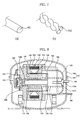
- FIG. 8 is a sectional view illustrating the interior configuration of the linear compressor having a linear motor.
- the linear compressor comprises a hermetic container 104 including a lower container 101 having an open upper surface, and an upper cover 102 configured to cover the lower container 101.
- a cylinder block 110 having a cylinder 109 is mounted in the hermetic container 104 in a shock-absorbing manner. Also, a back cover 120 having a refrigerant suction channel 120a is supported relative to the cylinder block 110 in a shock-absorbing manner.
- the back cover 120 is spaced apart from the cylinder block 110.
- the linear compressor further comprises a piston 130, a linear motor 140, a suction valve 160, and a discharge valve 170.
- the piston 130 is located to be linearly reciprocated in the cylinder 109, and is internally formed with a refrigerant passage 130a to guide the refrigerant, introduced from the refrigerant suction channel 120a, into the cylinder 109.
- the linear motor 140 is connected to the piston 130 to linearly reciprocate the piston 130.
- the suction valve 160 is mounted to the piston 130 and is operated by the gaseous refrigerant to open or close the refrigerant passage 130a.
- the discharge valve 170 is mounted to the cylinder block 110 so that a compression chamber C is defined in the cylinder 109 between the discharge valve 170 and the piston 130.
- the discharge valve 170 is also operated by the gaseous refrigerant to open or close the cylinder 109.
- the piston 130 has a radially protruding fixing portion 132 formed at one end thereof so that the linear motor 140 is connected to the fixing portion 132.
- the piston 130 is supported in a shock-absorbing manner between the cylinder block 110 and the back cover 120 by means of first and second springs 133 and 134.
- the first spring 133 is interposed between one surface of the fixing portion 132 and the cylinder block 110
- the second spring 134 is interposed between the other surface of the fixing portion 132 and the back cover 120.
- the linear motor 140 includes a stator and a mover.
- the fixing portion 132 of the piston 130 is coupled to a certain location of the mover. Thereby, if the mover is linearly reciprocated by a magnetic force produced in the stator, the piston 130 is linearly reciprocated in the cylinder 109.
- the stator includes an outer core 141 in the form of a stack, an inner core 142 in the form of a stack and spaced apart from the outer core 141, and a coil assembly 143 mounted in the outer core 141.
- the configuration of the coil assembly 143 has been explained hereinbefore in detail in connection with the linear motor.
- the outer core 141 is disposed at facing surfaces of both the cylinder block 110 and the back cover 120, and is coupled thereto by means of fastening members, etc.
- the inner core 142 is coupled to the cylinder block 110 by means of fastening members.
- the mover includes a magnet 150 located between the outer core 141 and the inner core 142, and a magnet frame 154 disposed between the outer core 141 and the inner core 142 to be linearly reciprocated.
- the magnet frame 154 is connected to both the magnet 150 and the piston 130.
- the discharge valve 170 and the suction valve 160 operate according to the linear reciprocating movement of the piston 130 to introduce the gaseous refrigerant inside the hermetic container 104 into the compression chamber C and to discharge the compressed refrigerant from the compression chamber C.
- Reference numeral 180 denotes a suction pipe connected to a certain location of the hermetic container 104 to introduce exterior refrigerant into the hermetic container 104
- reference numeral 182 denotes a discharge valve pipe connected to the discharge valve 170
- reference numeral 184 denotes a loop pipe having a first end connected to the discharge pipe 182
- reference numeral 186 denotes a discharge pipe having a first end connected to a second end of the loop pipe 184 and a second end to penetrate through the hermetic container 104 to thereby protrude out of the hermetic container 104.
- the linear motor and the linear compressor using the same operate in the power mode, and the relay 90 is connected to the first connecting tap 82 that is connected to the second ends of the first and second main coils 61 and 71 and the first end of the auxiliary coils 62 and 72.
- the AC power from the power supply unit that is connected to the end of the relay 90, is supplied to the respective first and second main coils 61 and 71.
- the supplied AC power is equally applied to the respective first and second main coils 61 and 71.
- the linear motor and the linear compressor operate in the save mode, and the relay 90 is connected to the second connecting tap 83. Since the second connecting tap 73 is connected to the second end of the first and second auxiliary coils 62 and 72 that are connected in series, both the auxiliary coils 62 and 72 are connected to the relay 90 in series. Thereby, the AC power is applied to the entire coil groups including the auxiliary coils 62 and 72 connected in series and the main coils 61 and 71 connected in parallel.
- the main coils 61 and 71 are connected to the auxiliary coils 62 and 72 in series, if the AC power is applied to the entire coil groups, the AC power is distributed to the respective coils depending on the capacity of the respective coils.
- the supplied AC power is divided to be applied to the main coils 61 and 71, the first auxiliary coil 62, and the second auxiliary coil 72, respectively.
- the electric current flowing through the respective coils has a small value, and consequently, the coils produce a low strength magnetic field therearound, allowing the magnet 150 to be linearly reciprocated with a shortened stroke.
- a plurality of coil conductors are wound to form a plurality of coil groups and the plurality of coil groups are connected in series or in parallel, so that the capacity of the coils is variable depending on a load applied to the linear motor. This effectively improves the efficiency of the linear motor.
- the coils having a small outer diameter are connected in parallel to achieve the same effect as that achieved by a coil having a large cross sectional area. This improves the efficiency of the motor with a reduced motor size, thereby preventing resource consumption of electricity and reducing manufacturing costs of the linear motor and the linear compressor.
Abstract
Description
- The present invention relates to a linear motor and a linear compressor using the same. It particularly, relates to a linear motor and a linear compressor using the same wherein a plurality of coil groups, provided in the linear motor, are connected in series or in parallel, and driving power is applied to part or all of the coil groups depending on the magnitude of load current applied to the linear motor. Embodiments of the present invention can provide a linear motor which achieves an improved efficiency with a reduced size.
- Generally, a compressor is an apparatus to compress fluid, such as air or gaseous refrigerant. In particular, a linear compressor is designed to introduce, compress, and discharge gaseous refrigerant through a linear reciprocating movement of a piston in a cylinder, which is performed by a linear driving force of a linear motor.
- Known linear compressors comprises a hermetic container having a suction pipe that is connected to a certain location of the hermetic container to introduce refrigerant into the hermetic container, a cylinder mounted in the hermetic container and having a refrigerant compression chamber therein, a piston mounted to be linearly reciprocated in the cylinder and adapted to introduce the refrigerant into the compression chamber to thereby compress it therein, and a linear motor connected to an end of the piston to provide a driving force required to linearly reciprocate the piston.
- The linear motor includes a stator having a coil assembly, and a mover having a magnet and a magnet frame to connect the magnet to the piston.
- As shown in FIG. 1, a known linear motor 1 includes a
coil assembly 2 to produce a magnetic field when AC power is applied thereto, and a relay 5 to selectively transmit the AC power to thecoil assembly 2. - The linear motor 1 is designed to vary the magnitude of a magnetic field depending on a load applied thereto, thereby achieving improved motor efficiency.
- For this, the
coil assembly 2, provided in the linear motor 1, consists of a main coil Cm and an auxiliary coil Cs. When the applied load is high, the linear motor 1 operates in a power mode wherein the relay 5 is connected to a connectingterminal 3 of the main coil Cm to increase the magnitude of electric current flowing into the main coil Cm. This increases the strength of the resulting magnetic field, achieving a lengthened stoke of a piston. - Conversely, when the applied load is low, the linear motor 1 operates in a save mode wherein the relay 5 is connected to a connecting terminal 4 of the main coil Cm and the auxiliary coil Cs to decrease the magnitude of electric current flowing into both the main coil Cm and the auxiliary coil Cs. This decreases the strength of the resulting magnetic field, achieving a shortened stoke of the piston.
- FIG. 2 is a diagram illustrating the coil assembly of the known linear motor shown in figure 1.
- The
coil assembly 2 includes a bobbin, and coils wound plural turns on the bobbin and adapted to produce a magnetic field when electric voltage is applied thereto. - As described above, the coils include the main coil Cm immediately disposed on the bobbin, and the auxiliary coil Cs disposed around the main coil Cm. The main coil Cm and the auxiliary coil Cs are connected in series.
- However, the known linear motor configured and operated as stated above has a problem in that the size of the linear motor should be large to ensure successful operation of the liner motor in the low-load save mode.
- Specifically, since the coils are conductive wires, such as copper wires, they basically have a predetermined magnitude of resistance. Generally, the resistance of a conductive wire is proportional to the length of the wire and inversely proportional to the cross sectional area of the wire.
- Therefore, in the case of the save mode wherein driving power is applied to both the main coil Cm and the auxiliary coil Cs connected in series, the resistance of the wire increases due to the increased coil length, and consequently, the electricity consumption of the wire itself increases, resulting in deteriorated motor efficiency.
- To solve the above problem, it may be regarded that a conducting wire having a large cross sectional area is used to reduce the resistance of the save mode to a level of the power mode. This solution is effective to improve the efficiency of the motor, but is still problematic because it unnecessarily increases the cross sectional area of the coil in the case of the low-load save mode, resulting in an increased motor size.
- In particular, the linear motor is configured in such a fashion that the conductive wires (hereinafter, referred to as coil conductors) of the main and auxiliary coils are closely wound on the bobbin to be stacked one above another. However, if the cross sectional areas of the coil conductors increase, it is very difficult to wind the coils in the above manner.
- The present invention has been made in view of the above-mentioned problems.
- Embodiments of the present invention provide a linear motor and a linear compressor using the same, in which a plurality of coil groups, provided in the linear motor, are connected in series or in parallel, and driving power is applied to part or all of the coil groups depending on the magnitude of load current applied to the linear motor, whereby the linear motor achieves improved efficiency with a reduced size.
- Embodiments of the present invention also provide a linear motor and a linear compressor using the same, wherein a plurality of coil conductors are used to form coil groups of the linear motor, whereby a manufacturing process of the linear motor can be considerably simplified as compared to a known method of winding coil conductors each having a large cross sectional area on a bobbin.
- In accordance with a first aspect of the present invention, there is provided a linear motor comprising: a bobbin; a plurality of coil groups wound on the bobbin and connected to each other in series or in parallel to allow driving power to be applied to part or all of the coil groups; and a magnet adapted to be linearly reciprocated under the influence of a magnetic field that is produced by the coil groups depending on load current flowing through the coil groups.
- The coil groups may include first and second coil groups each consisting of one or more coils stacked one above another on the bobbin.
- The first and second coil groups may have first and second main coils immediately disposed on the bobbin, and first and second auxiliary coils disposed around the first and second main coils, the first and second main coils may be connected to each other in parallel, and the first and second main coils may be twisted together prior to being wound on the bobbin.
- In accordance with a second aspect of the present invention, there is provided a linear compressor comprising: a cylinder block having a cylinder; a back cover spaced apart from the cylinder block and having a refrigerant suction channel; an outer core disposed between the cylinder block and the back cover; a coil assembly mounted in the outer core and including a plurality of coil groups that are connected to each other in series or in parallel to allow driving power to be selectively applied thereto depending on the magnitude of load current; an inner core spaced apart from the outer core; a magnet located between the outer core and the inner core and adapted to be linearly reciprocated under the influence of a magnetic field that is produced by the coil assembly; a piston connected to the magnet to be linearly reciprocated in the cylinder and having a refrigerant passage formed therein; a suction valve mounted to the piston to open or close the refrigerant passage; and a discharge valve mounted to the cylinder block to open or close the cylinder.
- In embodiments having the linear motor and the linear compressor using the same are configured as stated above, a plurality of coil conductors are wound to form a plurality of coil groups and the plurality of coil groups are connected in series or in parallel, so that the capacity (or impedance) of the coils is variable depending on a load applied to the linear motor. This effectively improves the efficiency of the linear motor. Also, using the coil conductors having a small cross sectional area enables reduction in the size of the linear motor.
- Embodiments of the invention will now be described by way of non-limiting example only, with reference to the drawings, in which:
- FIG. 1 is a circuit diagram of a known linear motor;
- FIG. 2 is a schematic diagram illustrating a coil assembly of the known linear motor;
- FIG. 3 is a circuit diagram of a linear motor;
- FIG. 4 is a wiring diagram illustrating wiring of coils provided in the linear motor;
- FIG. 5 is a schematic diagram illustrating a coil assembly of the linear motor;
- FIG. 6 is a view illustrating the winding structure of the coils provided in the linear motor;
- FIGS. 7a and 7b are comparative views of two coils having different cross sectional areas, FIG. 7a illustrating the coil of the known linear motor, FIG. 7b illustrating the coil of the linear motor; and
- FIG. 8 is a sectional view illustrating the interior configuration of a linear compressor having the linear motor.
- For reference, there may be provided several embodiments of the linear motor and the linear compressor, and hereinafter, a particular embodiment will be explained.
- FIG. 3 is a circuit diagram of a linear motor. The linear motor comprises a power supply unit to apply AC power, supplied from an exterior source, to a
linear motor body 50, thelinear motor body 50 to perform a linear reciprocating movement upon receiving the AC power applied from the power supply unit, and aswitch 90 connected between thelinear motor body 50 and the power supply unit to apply the AC power from the power source to part or all of coils mounted in thelinear motor body 50. - The
linear motor body 50 includes a stator (not shown) and a mover (not shown). The mover is connected at a certain location thereof to a fixing portion of a piston. Thereby, if the mover is linearly reciprocated under the influence of a magnetic field produced in the stator, the piston, connected to the mover, compresses a refrigerant while being linearly reciprocated in a cylinder. - The stator of the
linear motor body 50 includes an outer core in the form of a stack, an inner core in the form of a stack and inwardly spaced apart from the outer core, and a coil assembly mounted in the outer core. The coil assembly includes a plurality of coils adapted to produce a magnetic field when electric voltage is applied thereto. - The mover includes a magnet located between the outer core and the inner core and connected to the piston.
- The plurality of coils of the coil assembly includes main coils Cm, and auxiliary coils Cs. The main coils Cm are connected in parallel, and the auxiliary coils Cs are connected in series.
- The coil assembly further includes a
ground tap 81 connected at one end thereof to first ends of the respective main coils Cm connected in parallel, the other end of theground tap 81 being connected to a ground end of the power supply unit, a first connectingtap 82 connected to second ends of the respective main coils Cm and a first end of the auxiliary coils Cs connected in series, and a second connectingtap 83 connected to a second end of the auxiliary coils Cs. - The
switch 90 is a device to allow the AC power of the power supply unit to be selectively applied to the coil assembly. Theswitch 90 is may be a relay, but the present invention is not limited thereto. - When the
switch 90 is connected to the first connectingtap 82, the AC power from the power supply unit is applied to the main coils Cm. Also, when theswitch 90 is connected to the second connectingtap 83, the AC power is applied to the main coils Cm and the auxiliary coils Cs. - FIG. 4 is a wiring diagram illustrating wiring of the coils provided in the linear motor. The coils of the coil assembly form a plurality of coil groups, which are formed by winding a plurality of coil conductors, respectively.
- In this case, although the number of the coil groups is not limited to a specific number, for the convenience of explanation, the following description is based on the assumption that first and second coil groups are formed, each coil group being formed by winding two coil conductors.
- The
first coil group 60 includes a firstmain coil 61 and a firstauxiliary coil 62, and thesecond coil group 70 includes a secondmain coil 71 and a secondauxiliary coil 72. The first and secondmain coils auxiliary coils - In this case, the first and second
main coils auxiliary coils - The
ground tap 81, which is connected to the ground tap of the power supply unit, is connected to the first ends of the first and secondmain coils tap 82, to which the AC power is applied, is provided between themain coils auxiliary coils main coils tap 82. - The first and second
auxiliary coils tap 83 to thereby considerably reduce the magnitude of load current. - FIG. 5 is a schematic diagram illustrating the coil assembly of a linear motor. FIG. 6 is a view illustrating the winding structure of the coils provided in the linear motor.
- The coil assembly includes a bobbin, and the first and
second coil groups - As can be seen from FIG. 6, the first and
second coil groups first coil group 60 may be smaller or larger than that of the coil conductor that forms thesecond coil group 70. - Hereinafter, for the convenience of explanation, one of the coil groups, located at the left side of FIG. 5, is designated as the
first coil group 60, and the other coil group, located at the right side of FIG. 5, is designated as thesecond coil group 70. - As stated above, each of the
coil groups - In this case, the first and second
main coils coils - FIGS. 7a and 7b are comparative views of two coils having different cross sectional areas, FIG. 7a illustrating the coil of the known linear motor, FIG. 7b illustrating the coil of the linear motor.
- In the linear motor and the linear compressor using the same, the coil assembly is formed by connecting the plurality of coil conductors, having a smaller outer diameter than that of the known coil conductor, in series or in parallel.
- As stated above, when the linear motor operates in the power mode, the AC power is applied to the coils connected in parallel. Thus, when the respective coil conductors have a radius R2 as shown in Fig. 7b, the sum of the radii R2 of the coil conductors is equal to the radius of the twisted coils. As will be easily understood by comparing Figs. 7a and 7b, the sum of the radii R2 of the respective coils is similar to a radius R1 of the known coil. In this way, the cross sectional area of the coil conductors, i.e. the capacity of the coils in the sense of the mechanical force exertable thereby, increases to suit the high-load power mode.
- Also, when the linear motor operates in the save mode, the AC power is applied to all of the main coils connected in parallel and the auxiliary coils connected in series. Also, the main coils and the auxiliary coils of the coil groups are connected in series. With this connection structure, the capacity of the coils, to which the AC power is applied, decreases to suit the low-load save mode.
- With embodiments of the present invention, therefore, even if coils are formed by winding coil conductors having small cross sectional areas, there is no loss in the efficiency of the linear motor.
- Now, the configuration of a linear compressor, in which the linear motor configured and operated as stated above is mounted, will be explained. FIG. 8 is a sectional view illustrating the interior configuration of the linear compressor having a linear motor.
- The linear compressor comprises a
hermetic container 104 including alower container 101 having an open upper surface, and anupper cover 102 configured to cover thelower container 101. - A
cylinder block 110 having acylinder 109 is mounted in thehermetic container 104 in a shock-absorbing manner. Also, aback cover 120 having arefrigerant suction channel 120a is supported relative to thecylinder block 110 in a shock-absorbing manner. - Here, the
back cover 120 is spaced apart from thecylinder block 110. - The linear compressor further comprises a
piston 130, alinear motor 140, asuction valve 160, and adischarge valve 170. Thepiston 130 is located to be linearly reciprocated in thecylinder 109, and is internally formed with arefrigerant passage 130a to guide the refrigerant, introduced from therefrigerant suction channel 120a, into thecylinder 109. Thelinear motor 140 is connected to thepiston 130 to linearly reciprocate thepiston 130. Thesuction valve 160 is mounted to thepiston 130 and is operated by the gaseous refrigerant to open or close therefrigerant passage 130a. Thedischarge valve 170 is mounted to thecylinder block 110 so that a compression chamber C is defined in thecylinder 109 between thedischarge valve 170 and thepiston 130. Thedischarge valve 170 is also operated by the gaseous refrigerant to open or close thecylinder 109. - The
piston 130 has a radially protruding fixingportion 132 formed at one end thereof so that thelinear motor 140 is connected to the fixingportion 132. Thepiston 130 is supported in a shock-absorbing manner between thecylinder block 110 and theback cover 120 by means of first andsecond springs first spring 133 is interposed between one surface of the fixingportion 132 and thecylinder block 110, and thesecond spring 134 is interposed between the other surface of the fixingportion 132 and theback cover 120. - The
linear motor 140 includes a stator and a mover. The fixingportion 132 of thepiston 130 is coupled to a certain location of the mover. Thereby, if the mover is linearly reciprocated by a magnetic force produced in the stator, thepiston 130 is linearly reciprocated in thecylinder 109. - The stator includes an
outer core 141 in the form of a stack, aninner core 142 in the form of a stack and spaced apart from theouter core 141, and acoil assembly 143 mounted in theouter core 141. The configuration of thecoil assembly 143 has been explained hereinbefore in detail in connection with the linear motor. - The
outer core 141 is disposed at facing surfaces of both thecylinder block 110 and theback cover 120, and is coupled thereto by means of fastening members, etc. - The
inner core 142 is coupled to thecylinder block 110 by means of fastening members. - The mover includes a
magnet 150 located between theouter core 141 and theinner core 142, and amagnet frame 154 disposed between theouter core 141 and theinner core 142 to be linearly reciprocated. Themagnet frame 154 is connected to both themagnet 150 and thepiston 130. - The
discharge valve 170 and thesuction valve 160 operate according to the linear reciprocating movement of thepiston 130 to introduce the gaseous refrigerant inside thehermetic container 104 into the compression chamber C and to discharge the compressed refrigerant from the compression chamber C. -
Reference numeral 180 denotes a suction pipe connected to a certain location of thehermetic container 104 to introduce exterior refrigerant into thehermetic container 104,reference numeral 182 denotes a discharge valve pipe connected to thedischarge valve 170,reference numeral 184 denotes a loop pipe having a first end connected to thedischarge pipe 182, andreference numeral 186 denotes a discharge pipe having a first end connected to a second end of theloop pipe 184 and a second end to penetrate through thehermetic container 104 to thereby protrude out of thehermetic container 104. - Hereinafter, the operation of the linear motor and the linear compressor using the same will be explained.
- When high load is applied thereto, the linear motor and the linear compressor using the same operate in the power mode, and the
relay 90 is connected to the first connectingtap 82 that is connected to the second ends of the first and secondmain coils auxiliary coils - If the first connecting
tap 72 is connected to therelay 90, the AC power, from the power supply unit that is connected to the end of therelay 90, is supplied to the respective first and secondmain coils main coils main coils - As a result of supplying the AC power to the respective first and second
main coils magnet 150 to be linearly reciprocated with a lengthened stroke. - Then, the linear reciprocating movement of the
magnet 150 is transmitted to thepiston 130 via themagnet frame 154, whereby thepiston 130 operates to compress the gaseous refrigerant in the compression chamber C while being linearly reciprocated in thecylinder 109. - Meanwhile, when low load is applied thereto, the linear motor and the linear compressor operate in the save mode, and the
relay 90 is connected to the second connectingtap 83. Since the second connecting tap 73 is connected to the second end of the first and secondauxiliary coils auxiliary coils relay 90 in series. Thereby, the AC power is applied to the entire coil groups including theauxiliary coils main coils - Since the
main coils auxiliary coils auxiliary coils main coils auxiliary coil 62, and the secondauxiliary coil 72, respectively. - Therefore, the electric current flowing through the respective coils has a small value, and consequently, the coils produce a low strength magnetic field therearound, allowing the
magnet 150 to be linearly reciprocated with a shortened stroke. - As is apparent from the above description, a linear compressor is provided having the following effects.
- Firstly, a plurality of coil conductors are wound to form a plurality of coil groups and the plurality of coil groups are connected in series or in parallel, so that the capacity of the coils is variable depending on a load applied to the linear motor. This effectively improves the efficiency of the linear motor.
- Secondly, the coils having a small outer diameter are connected in parallel to achieve the same effect as that achieved by a coil having a large cross sectional area. This improves the efficiency of the motor with a reduced motor size, thereby preventing resource consumption of electricity and reducing manufacturing costs of the linear motor and the linear compressor.
- Thirdly, using the small diameter coils enables easy alignment and winding of the coils, resulting in simplified manufacturing process of the linear motor and the linear compressor using the same.
- Although particular embodiments of the present invention have been disclosed for illustrative purposes, those skilled in the art will appreciate that various modifications, additions and substitutions are possible, without departing from the scope of the invention as disclosed in the accompanying claims.
Claims (17)
- A linear motor comprising:a bobbin;a plurality of coil groups wound on the bobbin and connected to each other in series or in parallel to allow driving power to be applied to part or all of the coil groups; anda magnet adapted to be linearly reciprocated under the influence of a magnetic field that is produced by the coil groups depending on load current flowing through the coil groups.
- The linear motor as set forth in claim 1, wherein the coil groups include first and second coil groups each consisting of one or more coils stacked one above another on the bobbin.
- The linear motor as set forth in claim 2, wherein the first and second coil groups are formed of first and second coil conductors, respectively, the first coil conductor having a different outer diameter from that of the second coil conductor.
- The linear motor as set forth in claim 3, wherein the outer diameter of the first coil conductor of the first coil group is smaller than that of the second coil conductor of the second coil group.
- The linear motor as set forth in claim 2, wherein the first and second coil groups have first and second main coils immediately disposed on the bobbin, and first and second auxiliary coils disposed around the first and second main coils.
- The linear motor as set forth in claim 5, wherein the first and second main coils are connected to each other in parallel.
- The linear motor as set forth in claim 6, wherein the first and second main coils are twisted together prior to being wound on the bobbin.
- The linear motor as set forth in claim 5, wherein the first and second auxiliary coils are connected to each other in series.
- The linear motor as set forth in claim 5, wherein:a ground tap is connected to first ends of the first and second main coils connected in parallel;a first connecting tap is connected to second ends of the first and second main coils connected in parallel and a first end of the first and second auxiliary coils connected in series; anda second connecting tap is connected to a second end of the first and second auxiliary coils connected in series.
- The linear motor as set forth in claim 9, further comprising:a switch connected to part or all of the coil groups to apply the driving power thereto depending on the magnitude of load applied to the motor.
- The linear motor as set forth in claim 10, wherein the switch is a relay.
- The linear motor as set forth in claim 10, wherein:when the applied load is high, the switch is connected to the first connecting tap to apply the driving power to the first and second main coils; andwhen the applied load is low, the switch is connected to the second connecting tap to apply the driving power to all the first and second main coils and the first and second auxiliary coils.
- A linear compressor comprising:a cylinder block having a cylinder;a back cover spaced apart from the cylinder block and having a refrigerant suction channel;an outer core disposed between the cylinder block and the back cover;a coil assembly mounted in the outer core and including a plurality of coil groups that are connected to each other in series or in parallel to allow driving power to be selectively applied thereto depending on the magnitude of load current;an inner core spaced apart from the outer core;a magnet located between the outer core and the inner core and adapted to be linearly reciprocated under the influence of a magnetic field that is produced by the coil assembly;a piston connected to the magnet to be linearly reciprocated in the cylinder and having a refrigerant passage formed therein;a suction valve mounted to the piston to open or close the refrigerant passage; anda discharge valve mounted to the cylinder block to open or close the cylinder.
- The linear compressor as set forth in claim 13, wherein: the coil assembly includes first and second coil groups each consisting of one or more coils stacked one above another; and the coils are main coils and auxiliary coils, which are connected to each other in series.
- The linear compressor as set forth in claim 14, wherein the main coils of the first and second coil groups are connected to each other in parallel.
- The linear compressor as set forth in claim 14, wherein the auxiliary coils of the first and second coil groups are connected to each other in series.
- The linear compressor as set forth in claim 14, wherein the coil assembly includes connecting taps to apply the driving power to opposite ends of the main and auxiliary coils and between the main coils and the auxiliary coils.
Applications Claiming Priority (1)
| Application Number | Priority Date | Filing Date | Title |
|---|---|---|---|
| KR1020050057173A KR100846472B1 (en) | 2005-06-29 | 2005-06-29 | Linear Motor |
Publications (2)
| Publication Number | Publication Date |
|---|---|
| EP1739812A2 true EP1739812A2 (en) | 2007-01-03 |
| EP1739812A3 EP1739812A3 (en) | 2007-10-31 |
Family
ID=35744740
Family Applications (1)
| Application Number | Title | Priority Date | Filing Date |
|---|---|---|---|
| EP05257358A Ceased EP1739812A3 (en) | 2005-06-29 | 2005-11-30 | Linear motor and linear compressor using the same |
Country Status (5)
| Country | Link |
|---|---|
| US (1) | US7489055B2 (en) |
| EP (1) | EP1739812A3 (en) |
| JP (1) | JP4970771B2 (en) |
| KR (1) | KR100846472B1 (en) |
| CN (1) | CN1889342B (en) |
Cited By (1)
| Publication number | Priority date | Publication date | Assignee | Title |
|---|---|---|---|---|
| EP3422562A1 (en) * | 2017-06-29 | 2019-01-02 | B&R Industrial Automation GmbH | Method for operating a transport device in the form of a linear motor with guideway stator |
Families Citing this family (406)
| Publication number | Priority date | Publication date | Assignee | Title |
|---|---|---|---|---|
| US20070084897A1 (en) | 2003-05-20 | 2007-04-19 | Shelton Frederick E Iv | Articulating surgical stapling instrument incorporating a two-piece e-beam firing mechanism |
| US9060770B2 (en) | 2003-05-20 | 2015-06-23 | Ethicon Endo-Surgery, Inc. | Robotically-driven surgical instrument with E-beam driver |
| US8215531B2 (en) | 2004-07-28 | 2012-07-10 | Ethicon Endo-Surgery, Inc. | Surgical stapling instrument having a medical substance dispenser |
| US11896225B2 (en) | 2004-07-28 | 2024-02-13 | Cilag Gmbh International | Staple cartridge comprising a pan |
| KR100846472B1 (en) * | 2005-06-29 | 2008-07-17 | 엘지전자 주식회사 | Linear Motor |
| US9237891B2 (en) | 2005-08-31 | 2016-01-19 | Ethicon Endo-Surgery, Inc. | Robotically-controlled surgical stapling devices that produce formed staples having different lengths |
| US7669746B2 (en) | 2005-08-31 | 2010-03-02 | Ethicon Endo-Surgery, Inc. | Staple cartridges for forming staples having differing formed staple heights |
| US10159482B2 (en) | 2005-08-31 | 2018-12-25 | Ethicon Llc | Fastener cartridge assembly comprising a fixed anvil and different staple heights |
| US11484312B2 (en) | 2005-08-31 | 2022-11-01 | Cilag Gmbh International | Staple cartridge comprising a staple driver arrangement |
| US11246590B2 (en) | 2005-08-31 | 2022-02-15 | Cilag Gmbh International | Staple cartridge including staple drivers having different unfired heights |
| US7934630B2 (en) | 2005-08-31 | 2011-05-03 | Ethicon Endo-Surgery, Inc. | Staple cartridges for forming staples having differing formed staple heights |
| US20070106317A1 (en) | 2005-11-09 | 2007-05-10 | Shelton Frederick E Iv | Hydraulically and electrically actuated articulation joints for surgical instruments |
| US7753904B2 (en) | 2006-01-31 | 2010-07-13 | Ethicon Endo-Surgery, Inc. | Endoscopic surgical instrument with a handle that can articulate with respect to the shaft |
| US8708213B2 (en) | 2006-01-31 | 2014-04-29 | Ethicon Endo-Surgery, Inc. | Surgical instrument having a feedback system |
| US20110290856A1 (en) | 2006-01-31 | 2011-12-01 | Ethicon Endo-Surgery, Inc. | Robotically-controlled surgical instrument with force-feedback capabilities |
| US8186555B2 (en) | 2006-01-31 | 2012-05-29 | Ethicon Endo-Surgery, Inc. | Motor-driven surgical cutting and fastening instrument with mechanical closure system |
| US20120292367A1 (en) | 2006-01-31 | 2012-11-22 | Ethicon Endo-Surgery, Inc. | Robotically-controlled end effector |
| US7845537B2 (en) | 2006-01-31 | 2010-12-07 | Ethicon Endo-Surgery, Inc. | Surgical instrument having recording capabilities |
| US11224427B2 (en) | 2006-01-31 | 2022-01-18 | Cilag Gmbh International | Surgical stapling system including a console and retraction assembly |
| US8820603B2 (en) | 2006-01-31 | 2014-09-02 | Ethicon Endo-Surgery, Inc. | Accessing data stored in a memory of a surgical instrument |
| US20110024477A1 (en) | 2009-02-06 | 2011-02-03 | Hall Steven G | Driven Surgical Stapler Improvements |
| US11278279B2 (en) | 2006-01-31 | 2022-03-22 | Cilag Gmbh International | Surgical instrument assembly |
| US11793518B2 (en) | 2006-01-31 | 2023-10-24 | Cilag Gmbh International | Powered surgical instruments with firing system lockout arrangements |
| US8992422B2 (en) | 2006-03-23 | 2015-03-31 | Ethicon Endo-Surgery, Inc. | Robotically-controlled endoscopic accessory channel |
| US8322455B2 (en) | 2006-06-27 | 2012-12-04 | Ethicon Endo-Surgery, Inc. | Manually driven surgical cutting and fastening instrument |
| US10568652B2 (en) | 2006-09-29 | 2020-02-25 | Ethicon Llc | Surgical staples having attached drivers of different heights and stapling instruments for deploying the same |
| US8348131B2 (en) | 2006-09-29 | 2013-01-08 | Ethicon Endo-Surgery, Inc. | Surgical stapling instrument with mechanical indicator to show levels of tissue compression |
| US11291441B2 (en) | 2007-01-10 | 2022-04-05 | Cilag Gmbh International | Surgical instrument with wireless communication between control unit and remote sensor |
| US8652120B2 (en) | 2007-01-10 | 2014-02-18 | Ethicon Endo-Surgery, Inc. | Surgical instrument with wireless communication between control unit and sensor transponders |
| US8684253B2 (en) | 2007-01-10 | 2014-04-01 | Ethicon Endo-Surgery, Inc. | Surgical instrument with wireless communication between a control unit of a robotic system and remote sensor |
| US11039836B2 (en) | 2007-01-11 | 2021-06-22 | Cilag Gmbh International | Staple cartridge for use with a surgical stapling instrument |
| US8540128B2 (en) | 2007-01-11 | 2013-09-24 | Ethicon Endo-Surgery, Inc. | Surgical stapling device with a curved end effector |
| KR100810845B1 (en) * | 2007-03-14 | 2008-03-06 | 엘지전자 주식회사 | Linear compressor |
| US7438209B1 (en) | 2007-03-15 | 2008-10-21 | Ethicon Endo-Surgery, Inc. | Surgical stapling instruments having a releasable staple-forming pocket |
| GB2462021B (en) * | 2007-03-23 | 2011-12-07 | Otis Elevator Co | Electromagnet and elevator door coupler |
| US8893946B2 (en) | 2007-03-28 | 2014-11-25 | Ethicon Endo-Surgery, Inc. | Laparoscopic tissue thickness and clamp load measuring devices |
| US8931682B2 (en) | 2007-06-04 | 2015-01-13 | Ethicon Endo-Surgery, Inc. | Robotically-controlled shaft based rotary drive systems for surgical instruments |
| US11857181B2 (en) | 2007-06-04 | 2024-01-02 | Cilag Gmbh International | Robotically-controlled shaft based rotary drive systems for surgical instruments |
| US7753245B2 (en) | 2007-06-22 | 2010-07-13 | Ethicon Endo-Surgery, Inc. | Surgical stapling instruments |
| US11849941B2 (en) | 2007-06-29 | 2023-12-26 | Cilag Gmbh International | Staple cartridge having staple cavities extending at a transverse angle relative to a longitudinal cartridge axis |
| JP2009168476A (en) * | 2008-01-11 | 2009-07-30 | Hitachi High-Technologies Corp | Defect inspection method, and defect inspection system |
| US8758391B2 (en) | 2008-02-14 | 2014-06-24 | Ethicon Endo-Surgery, Inc. | Interchangeable tools for surgical instruments |
| US7866527B2 (en) | 2008-02-14 | 2011-01-11 | Ethicon Endo-Surgery, Inc. | Surgical stapling apparatus with interlockable firing system |
| US9179912B2 (en) | 2008-02-14 | 2015-11-10 | Ethicon Endo-Surgery, Inc. | Robotically-controlled motorized surgical cutting and fastening instrument |
| US8573465B2 (en) | 2008-02-14 | 2013-11-05 | Ethicon Endo-Surgery, Inc. | Robotically-controlled surgical end effector system with rotary actuated closure systems |
| RU2493788C2 (en) | 2008-02-14 | 2013-09-27 | Этикон Эндо-Серджери, Инк. | Surgical cutting and fixing instrument, which has radio-frequency electrodes |
| US8636736B2 (en) | 2008-02-14 | 2014-01-28 | Ethicon Endo-Surgery, Inc. | Motorized surgical cutting and fastening instrument |
| US7819298B2 (en) | 2008-02-14 | 2010-10-26 | Ethicon Endo-Surgery, Inc. | Surgical stapling apparatus with control features operable with one hand |
| US10390823B2 (en) | 2008-02-15 | 2019-08-27 | Ethicon Llc | End effector comprising an adjunct |
| US11272927B2 (en) | 2008-02-15 | 2022-03-15 | Cilag Gmbh International | Layer arrangements for surgical staple cartridges |
| US8210411B2 (en) | 2008-09-23 | 2012-07-03 | Ethicon Endo-Surgery, Inc. | Motor-driven surgical cutting instrument |
| US11648005B2 (en) | 2008-09-23 | 2023-05-16 | Cilag Gmbh International | Robotically-controlled motorized surgical instrument with an end effector |
| US9386983B2 (en) | 2008-09-23 | 2016-07-12 | Ethicon Endo-Surgery, Llc | Robotically-controlled motorized surgical instrument |
| US9005230B2 (en) | 2008-09-23 | 2015-04-14 | Ethicon Endo-Surgery, Inc. | Motorized surgical instrument |
| US8608045B2 (en) | 2008-10-10 | 2013-12-17 | Ethicon Endo-Sugery, Inc. | Powered surgical cutting and stapling apparatus with manually retractable firing system |
| US8517239B2 (en) | 2009-02-05 | 2013-08-27 | Ethicon Endo-Surgery, Inc. | Surgical stapling instrument comprising a magnetic element driver |
| BRPI1008667A2 (en) | 2009-02-06 | 2016-03-08 | Ethicom Endo Surgery Inc | improvement of the operated surgical stapler |
| US8444036B2 (en) | 2009-02-06 | 2013-05-21 | Ethicon Endo-Surgery, Inc. | Motor driven surgical fastener device with mechanisms for adjusting a tissue gap within the end effector |
| US7772737B1 (en) | 2009-02-25 | 2010-08-10 | Emerson Electric Co. | Two conductor winding for an induction motor circuit |
| US8851354B2 (en) | 2009-12-24 | 2014-10-07 | Ethicon Endo-Surgery, Inc. | Surgical cutting instrument that analyzes tissue thickness |
| US8220688B2 (en) | 2009-12-24 | 2012-07-17 | Ethicon Endo-Surgery, Inc. | Motor-driven surgical cutting instrument with electric actuator directional control assembly |
| US8783543B2 (en) | 2010-07-30 | 2014-07-22 | Ethicon Endo-Surgery, Inc. | Tissue acquisition arrangements and methods for surgical stapling devices |
| US11925354B2 (en) | 2010-09-30 | 2024-03-12 | Cilag Gmbh International | Staple cartridge comprising staples positioned within a compressible portion thereof |
| US9566061B2 (en) | 2010-09-30 | 2017-02-14 | Ethicon Endo-Surgery, Llc | Fastener cartridge comprising a releasably attached tissue thickness compensator |
| US11298125B2 (en) | 2010-09-30 | 2022-04-12 | Cilag Gmbh International | Tissue stapler having a thickness compensator |
| US9364233B2 (en) | 2010-09-30 | 2016-06-14 | Ethicon Endo-Surgery, Llc | Tissue thickness compensators for circular surgical staplers |
| US9241714B2 (en) | 2011-04-29 | 2016-01-26 | Ethicon Endo-Surgery, Inc. | Tissue thickness compensator and method for making the same |
| US9517063B2 (en) | 2012-03-28 | 2016-12-13 | Ethicon Endo-Surgery, Llc | Movable member for use with a tissue thickness compensator |
| US11812965B2 (en) | 2010-09-30 | 2023-11-14 | Cilag Gmbh International | Layer of material for a surgical end effector |
| US8740038B2 (en) | 2010-09-30 | 2014-06-03 | Ethicon Endo-Surgery, Inc. | Staple cartridge comprising a releasable portion |
| US9386988B2 (en) | 2010-09-30 | 2016-07-12 | Ethicon End-Surgery, LLC | Retainer assembly including a tissue thickness compensator |
| US9629814B2 (en) | 2010-09-30 | 2017-04-25 | Ethicon Endo-Surgery, Llc | Tissue thickness compensator configured to redistribute compressive forces |
| US10945731B2 (en) | 2010-09-30 | 2021-03-16 | Ethicon Llc | Tissue thickness compensator comprising controlled release and expansion |
| US8695866B2 (en) | 2010-10-01 | 2014-04-15 | Ethicon Endo-Surgery, Inc. | Surgical instrument having a power control circuit |
| AU2012250197B2 (en) | 2011-04-29 | 2017-08-10 | Ethicon Endo-Surgery, Inc. | Staple cartridge comprising staples positioned within a compressible portion thereof |
| US11207064B2 (en) | 2011-05-27 | 2021-12-28 | Cilag Gmbh International | Automated end effector component reloading system for use with a robotic system |
| US9072535B2 (en) | 2011-05-27 | 2015-07-07 | Ethicon Endo-Surgery, Inc. | Surgical stapling instruments with rotatable staple deployment arrangements |
| US9044230B2 (en) | 2012-02-13 | 2015-06-02 | Ethicon Endo-Surgery, Inc. | Surgical cutting and fastening instrument with apparatus for determining cartridge and firing motion status |
| BR112014024102B1 (en) | 2012-03-28 | 2022-03-03 | Ethicon Endo-Surgery, Inc | CLAMP CARTRIDGE ASSEMBLY FOR A SURGICAL INSTRUMENT AND END ACTUATOR ASSEMBLY FOR A SURGICAL INSTRUMENT |
| JP6105041B2 (en) | 2012-03-28 | 2017-03-29 | エシコン・エンド−サージェリィ・インコーポレイテッドEthicon Endo−Surgery,Inc. | Tissue thickness compensator containing capsules defining a low pressure environment |
| MX353040B (en) | 2012-03-28 | 2017-12-18 | Ethicon Endo Surgery Inc | Retainer assembly including a tissue thickness compensator. |
| US9101358B2 (en) | 2012-06-15 | 2015-08-11 | Ethicon Endo-Surgery, Inc. | Articulatable surgical instrument comprising a firing drive |
| US9289256B2 (en) | 2012-06-28 | 2016-03-22 | Ethicon Endo-Surgery, Llc | Surgical end effectors having angled tissue-contacting surfaces |
| US20140001234A1 (en) | 2012-06-28 | 2014-01-02 | Ethicon Endo-Surgery, Inc. | Coupling arrangements for attaching surgical end effectors to drive systems therefor |
| BR112014032776B1 (en) | 2012-06-28 | 2021-09-08 | Ethicon Endo-Surgery, Inc | SURGICAL INSTRUMENT SYSTEM AND SURGICAL KIT FOR USE WITH A SURGICAL INSTRUMENT SYSTEM |
| EP2866686A1 (en) | 2012-06-28 | 2015-05-06 | Ethicon Endo-Surgery, Inc. | Empty clip cartridge lockout |
| US20140001231A1 (en) | 2012-06-28 | 2014-01-02 | Ethicon Endo-Surgery, Inc. | Firing system lockout arrangements for surgical instruments |
| US9649111B2 (en) | 2012-06-28 | 2017-05-16 | Ethicon Endo-Surgery, Llc | Replaceable clip cartridge for a clip applier |
| US9204879B2 (en) | 2012-06-28 | 2015-12-08 | Ethicon Endo-Surgery, Inc. | Flexible drive member |
| US11202631B2 (en) | 2012-06-28 | 2021-12-21 | Cilag Gmbh International | Stapling assembly comprising a firing lockout |
| BR112015021098B1 (en) | 2013-03-01 | 2022-02-15 | Ethicon Endo-Surgery, Inc | COVERAGE FOR A JOINT JOINT AND SURGICAL INSTRUMENT |
| MX364729B (en) | 2013-03-01 | 2019-05-06 | Ethicon Endo Surgery Inc | Surgical instrument with a soft stop. |
| US9888919B2 (en) | 2013-03-14 | 2018-02-13 | Ethicon Llc | Method and system for operating a surgical instrument |
| US9629629B2 (en) | 2013-03-14 | 2017-04-25 | Ethicon Endo-Surgey, LLC | Control systems for surgical instruments |
| US9867612B2 (en) | 2013-04-16 | 2018-01-16 | Ethicon Llc | Powered surgical stapler |
| BR112015026109B1 (en) | 2013-04-16 | 2022-02-22 | Ethicon Endo-Surgery, Inc | surgical instrument |
| MX369362B (en) | 2013-08-23 | 2019-11-06 | Ethicon Endo Surgery Llc | Firing member retraction devices for powered surgical instruments. |
| US9775609B2 (en) | 2013-08-23 | 2017-10-03 | Ethicon Llc | Tamper proof circuit for surgical instrument battery pack |
| US9962161B2 (en) | 2014-02-12 | 2018-05-08 | Ethicon Llc | Deliverable surgical instrument |
| BR112016019387B1 (en) | 2014-02-24 | 2022-11-29 | Ethicon Endo-Surgery, Llc | SURGICAL INSTRUMENT SYSTEM AND FASTENER CARTRIDGE FOR USE WITH A SURGICAL FIXING INSTRUMENT |
| US10028761B2 (en) | 2014-03-26 | 2018-07-24 | Ethicon Llc | Feedback algorithms for manual bailout systems for surgical instruments |
| US9826977B2 (en) | 2014-03-26 | 2017-11-28 | Ethicon Llc | Sterilization verification circuit |
| BR112016021943B1 (en) | 2014-03-26 | 2022-06-14 | Ethicon Endo-Surgery, Llc | SURGICAL INSTRUMENT FOR USE BY AN OPERATOR IN A SURGICAL PROCEDURE |
| US9820738B2 (en) | 2014-03-26 | 2017-11-21 | Ethicon Llc | Surgical instrument comprising interactive systems |
| US9801628B2 (en) | 2014-09-26 | 2017-10-31 | Ethicon Llc | Surgical staple and driver arrangements for staple cartridges |
| JP6612256B2 (en) | 2014-04-16 | 2019-11-27 | エシコン エルエルシー | Fastener cartridge with non-uniform fastener |
| JP6636452B2 (en) | 2014-04-16 | 2020-01-29 | エシコン エルエルシーEthicon LLC | Fastener cartridge including extension having different configurations |
| JP6532889B2 (en) | 2014-04-16 | 2019-06-19 | エシコン エルエルシーEthicon LLC | Fastener cartridge assembly and staple holder cover arrangement |
| US11517315B2 (en) | 2014-04-16 | 2022-12-06 | Cilag Gmbh International | Fastener cartridges including extensions having different configurations |
| US20150297225A1 (en) | 2014-04-16 | 2015-10-22 | Ethicon Endo-Surgery, Inc. | Fastener cartridges including extensions having different configurations |
| BR112017004361B1 (en) | 2014-09-05 | 2023-04-11 | Ethicon Llc | ELECTRONIC SYSTEM FOR A SURGICAL INSTRUMENT |
| US20160066913A1 (en) | 2014-09-05 | 2016-03-10 | Ethicon Endo-Surgery, Inc. | Local display of tissue parameter stabilization |
| US11311294B2 (en) | 2014-09-05 | 2022-04-26 | Cilag Gmbh International | Powered medical device including measurement of closure state of jaws |
| US10105142B2 (en) | 2014-09-18 | 2018-10-23 | Ethicon Llc | Surgical stapler with plurality of cutting elements |
| US11523821B2 (en) | 2014-09-26 | 2022-12-13 | Cilag Gmbh International | Method for creating a flexible staple line |
| CN107427300B (en) | 2014-09-26 | 2020-12-04 | 伊西康有限责任公司 | Surgical suture buttress and buttress material |
| US10076325B2 (en) | 2014-10-13 | 2018-09-18 | Ethicon Llc | Surgical stapling apparatus comprising a tissue stop |
| US9924944B2 (en) | 2014-10-16 | 2018-03-27 | Ethicon Llc | Staple cartridge comprising an adjunct material |
| US11141153B2 (en) | 2014-10-29 | 2021-10-12 | Cilag Gmbh International | Staple cartridges comprising driver arrangements |
| US10517594B2 (en) | 2014-10-29 | 2019-12-31 | Ethicon Llc | Cartridge assemblies for surgical staplers |
| US9844376B2 (en) | 2014-11-06 | 2017-12-19 | Ethicon Llc | Staple cartridge comprising a releasable adjunct material |
| US10736636B2 (en) | 2014-12-10 | 2020-08-11 | Ethicon Llc | Articulatable surgical instrument system |
| BR112017012996B1 (en) | 2014-12-18 | 2022-11-08 | Ethicon Llc | SURGICAL INSTRUMENT WITH AN ANvil WHICH IS SELECTIVELY MOVABLE ABOUT AN IMMOVABLE GEOMETRIC AXIS DIFFERENT FROM A STAPLE CARTRIDGE |
| US10245027B2 (en) | 2014-12-18 | 2019-04-02 | Ethicon Llc | Surgical instrument with an anvil that is selectively movable about a discrete non-movable axis relative to a staple cartridge |
| US9844375B2 (en) | 2014-12-18 | 2017-12-19 | Ethicon Llc | Drive arrangements for articulatable surgical instruments |
| US9844374B2 (en) | 2014-12-18 | 2017-12-19 | Ethicon Llc | Surgical instrument systems comprising an articulatable end effector and means for adjusting the firing stroke of a firing member |
| US10188385B2 (en) | 2014-12-18 | 2019-01-29 | Ethicon Llc | Surgical instrument system comprising lockable systems |
| US10085748B2 (en) | 2014-12-18 | 2018-10-02 | Ethicon Llc | Locking arrangements for detachable shaft assemblies with articulatable surgical end effectors |
| US9987000B2 (en) | 2014-12-18 | 2018-06-05 | Ethicon Llc | Surgical instrument assembly comprising a flexible articulation system |
| US10182816B2 (en) | 2015-02-27 | 2019-01-22 | Ethicon Llc | Charging system that enables emergency resolutions for charging a battery |
| US10180463B2 (en) | 2015-02-27 | 2019-01-15 | Ethicon Llc | Surgical apparatus configured to assess whether a performance parameter of the surgical apparatus is within an acceptable performance band |
| US11154301B2 (en) | 2015-02-27 | 2021-10-26 | Cilag Gmbh International | Modular stapling assembly |
| US10245033B2 (en) | 2015-03-06 | 2019-04-02 | Ethicon Llc | Surgical instrument comprising a lockable battery housing |
| US9808246B2 (en) | 2015-03-06 | 2017-11-07 | Ethicon Endo-Surgery, Llc | Method of operating a powered surgical instrument |
| JP2020121162A (en) | 2015-03-06 | 2020-08-13 | エシコン エルエルシーEthicon LLC | Time dependent evaluation of sensor data to determine stability element, creep element and viscoelastic element of measurement |
| US10441279B2 (en) | 2015-03-06 | 2019-10-15 | Ethicon Llc | Multiple level thresholds to modify operation of powered surgical instruments |
| US10687806B2 (en) | 2015-03-06 | 2020-06-23 | Ethicon Llc | Adaptive tissue compression techniques to adjust closure rates for multiple tissue types |
| US10052044B2 (en) | 2015-03-06 | 2018-08-21 | Ethicon Llc | Time dependent evaluation of sensor data to determine stability, creep, and viscoelastic elements of measures |
| US10617412B2 (en) | 2015-03-06 | 2020-04-14 | Ethicon Llc | System for detecting the mis-insertion of a staple cartridge into a surgical stapler |
| US9924961B2 (en) | 2015-03-06 | 2018-03-27 | Ethicon Endo-Surgery, Llc | Interactive feedback system for powered surgical instruments |
| US9901342B2 (en) | 2015-03-06 | 2018-02-27 | Ethicon Endo-Surgery, Llc | Signal and power communication system positioned on a rotatable shaft |
| US9993248B2 (en) | 2015-03-06 | 2018-06-12 | Ethicon Endo-Surgery, Llc | Smart sensors with local signal processing |
| US10390825B2 (en) | 2015-03-31 | 2019-08-27 | Ethicon Llc | Surgical instrument with progressive rotary drive systems |
| CN106330051A (en) * | 2015-06-19 | 2017-01-11 | 珠海格力电器股份有限公司 | Linear motor control circuit and linear motor |
| CN106340987B (en) * | 2015-07-14 | 2019-04-26 | 上海鸣志电器股份有限公司 | A kind of drag cup winding of integrated distribution |
| US10835249B2 (en) | 2015-08-17 | 2020-11-17 | Ethicon Llc | Implantable layers for a surgical instrument |
| US10105139B2 (en) | 2015-09-23 | 2018-10-23 | Ethicon Llc | Surgical stapler having downstream current-based motor control |
| US10238386B2 (en) | 2015-09-23 | 2019-03-26 | Ethicon Llc | Surgical stapler having motor control based on an electrical parameter related to a motor current |
| US10363036B2 (en) | 2015-09-23 | 2019-07-30 | Ethicon Llc | Surgical stapler having force-based motor control |
| US10327769B2 (en) | 2015-09-23 | 2019-06-25 | Ethicon Llc | Surgical stapler having motor control based on a drive system component |
| US10299878B2 (en) | 2015-09-25 | 2019-05-28 | Ethicon Llc | Implantable adjunct systems for determining adjunct skew |
| US10736633B2 (en) | 2015-09-30 | 2020-08-11 | Ethicon Llc | Compressible adjunct with looping members |
| US10980539B2 (en) | 2015-09-30 | 2021-04-20 | Ethicon Llc | Implantable adjunct comprising bonded layers |
| US10172620B2 (en) | 2015-09-30 | 2019-01-08 | Ethicon Llc | Compressible adjuncts with bonding nodes |
| US11890015B2 (en) | 2015-09-30 | 2024-02-06 | Cilag Gmbh International | Compressible adjunct with crossing spacer fibers |
| US10292704B2 (en) | 2015-12-30 | 2019-05-21 | Ethicon Llc | Mechanisms for compensating for battery pack failure in powered surgical instruments |
| US10368865B2 (en) | 2015-12-30 | 2019-08-06 | Ethicon Llc | Mechanisms for compensating for drivetrain failure in powered surgical instruments |
| US10265068B2 (en) | 2015-12-30 | 2019-04-23 | Ethicon Llc | Surgical instruments with separable motors and motor control circuits |
| CN105553218B (en) * | 2016-01-07 | 2018-04-17 | 瑞声光电科技(常州)有限公司 | Linear type vibration motor |
| US11213293B2 (en) | 2016-02-09 | 2022-01-04 | Cilag Gmbh International | Articulatable surgical instruments with single articulation link arrangements |
| US10588625B2 (en) | 2016-02-09 | 2020-03-17 | Ethicon Llc | Articulatable surgical instruments with off-axis firing beam arrangements |
| CN108882932B (en) | 2016-02-09 | 2021-07-23 | 伊西康有限责任公司 | Surgical instrument with asymmetric articulation configuration |
| US10448948B2 (en) | 2016-02-12 | 2019-10-22 | Ethicon Llc | Mechanisms for compensating for drivetrain failure in powered surgical instruments |
| US10258331B2 (en) | 2016-02-12 | 2019-04-16 | Ethicon Llc | Mechanisms for compensating for drivetrain failure in powered surgical instruments |
| US11224426B2 (en) | 2016-02-12 | 2022-01-18 | Cilag Gmbh International | Mechanisms for compensating for drivetrain failure in powered surgical instruments |
| US10485542B2 (en) | 2016-04-01 | 2019-11-26 | Ethicon Llc | Surgical stapling instrument comprising multiple lockouts |
| US10617413B2 (en) | 2016-04-01 | 2020-04-14 | Ethicon Llc | Closure system arrangements for surgical cutting and stapling devices with separate and distinct firing shafts |
| US10405859B2 (en) | 2016-04-15 | 2019-09-10 | Ethicon Llc | Surgical instrument with adjustable stop/start control during a firing motion |
| US10357247B2 (en) | 2016-04-15 | 2019-07-23 | Ethicon Llc | Surgical instrument with multiple program responses during a firing motion |
| US10492783B2 (en) | 2016-04-15 | 2019-12-03 | Ethicon, Llc | Surgical instrument with improved stop/start control during a firing motion |
| US10456137B2 (en) | 2016-04-15 | 2019-10-29 | Ethicon Llc | Staple formation detection mechanisms |
| US11179150B2 (en) | 2016-04-15 | 2021-11-23 | Cilag Gmbh International | Systems and methods for controlling a surgical stapling and cutting instrument |
| US10335145B2 (en) | 2016-04-15 | 2019-07-02 | Ethicon Llc | Modular surgical instrument with configurable operating mode |
| US11607239B2 (en) | 2016-04-15 | 2023-03-21 | Cilag Gmbh International | Systems and methods for controlling a surgical stapling and cutting instrument |
| US10828028B2 (en) | 2016-04-15 | 2020-11-10 | Ethicon Llc | Surgical instrument with multiple program responses during a firing motion |
| US10426467B2 (en) | 2016-04-15 | 2019-10-01 | Ethicon Llc | Surgical instrument with detection sensors |
| US10426469B2 (en) | 2016-04-18 | 2019-10-01 | Ethicon Llc | Surgical instrument comprising a primary firing lockout and a secondary firing lockout |
| US11317917B2 (en) | 2016-04-18 | 2022-05-03 | Cilag Gmbh International | Surgical stapling system comprising a lockable firing assembly |
| US20170296173A1 (en) | 2016-04-18 | 2017-10-19 | Ethicon Endo-Surgery, Llc | Method for operating a surgical instrument |
| US10639034B2 (en) | 2016-12-21 | 2020-05-05 | Ethicon Llc | Surgical instruments with lockout arrangements for preventing firing system actuation unless an unspent staple cartridge is present |
| US10835246B2 (en) | 2016-12-21 | 2020-11-17 | Ethicon Llc | Staple cartridges and arrangements of staples and staple cavities therein |
| US10980536B2 (en) | 2016-12-21 | 2021-04-20 | Ethicon Llc | No-cartridge and spent cartridge lockout arrangements for surgical staplers |
| US20180168618A1 (en) | 2016-12-21 | 2018-06-21 | Ethicon Endo-Surgery, Llc | Surgical stapling systems |
| US10898186B2 (en) | 2016-12-21 | 2021-01-26 | Ethicon Llc | Staple forming pocket arrangements comprising primary sidewalls and pocket sidewalls |
| US11134942B2 (en) | 2016-12-21 | 2021-10-05 | Cilag Gmbh International | Surgical stapling instruments and staple-forming anvils |
| US20180168615A1 (en) | 2016-12-21 | 2018-06-21 | Ethicon Endo-Surgery, Llc | Method of deforming staples from two different types of staple cartridges with the same surgical stapling instrument |
| US10695055B2 (en) | 2016-12-21 | 2020-06-30 | Ethicon Llc | Firing assembly comprising a lockout |
| US10485543B2 (en) | 2016-12-21 | 2019-11-26 | Ethicon Llc | Anvil having a knife slot width |
| US10537325B2 (en) | 2016-12-21 | 2020-01-21 | Ethicon Llc | Staple forming pocket arrangement to accommodate different types of staples |
| JP7010956B2 (en) | 2016-12-21 | 2022-01-26 | エシコン エルエルシー | How to staple tissue |
| US10888322B2 (en) | 2016-12-21 | 2021-01-12 | Ethicon Llc | Surgical instrument comprising a cutting member |
| US11419606B2 (en) | 2016-12-21 | 2022-08-23 | Cilag Gmbh International | Shaft assembly comprising a clutch configured to adapt the output of a rotary firing member to two different systems |
| US10426471B2 (en) | 2016-12-21 | 2019-10-01 | Ethicon Llc | Surgical instrument with multiple failure response modes |
| CN110099619B (en) | 2016-12-21 | 2022-07-15 | 爱惜康有限责任公司 | Lockout device for surgical end effector and replaceable tool assembly |
| US10542982B2 (en) | 2016-12-21 | 2020-01-28 | Ethicon Llc | Shaft assembly comprising first and second articulation lockouts |
| US10758230B2 (en) | 2016-12-21 | 2020-09-01 | Ethicon Llc | Surgical instrument with primary and safety processors |
| BR112019011947A2 (en) | 2016-12-21 | 2019-10-29 | Ethicon Llc | surgical stapling systems |
| US10610224B2 (en) | 2016-12-21 | 2020-04-07 | Ethicon Llc | Lockout arrangements for surgical end effectors and replaceable tool assemblies |
| TWI619886B (en) * | 2017-04-06 | 2018-04-01 | Matsushita Electric Taiwan Co Ltd | Compression |
| CN107023453B (en) * | 2017-05-23 | 2019-01-04 | 青岛中公联信息科技有限公司 | Linear compressor and refrigeration system |
| US10779820B2 (en) | 2017-06-20 | 2020-09-22 | Ethicon Llc | Systems and methods for controlling motor speed according to user input for a surgical instrument |
| US11071554B2 (en) | 2017-06-20 | 2021-07-27 | Cilag Gmbh International | Closed loop feedback control of motor velocity of a surgical stapling and cutting instrument based on magnitude of velocity error measurements |
| US10881396B2 (en) | 2017-06-20 | 2021-01-05 | Ethicon Llc | Surgical instrument with variable duration trigger arrangement |
| USD879809S1 (en) | 2017-06-20 | 2020-03-31 | Ethicon Llc | Display panel with changeable graphical user interface |
| US10646220B2 (en) | 2017-06-20 | 2020-05-12 | Ethicon Llc | Systems and methods for controlling displacement member velocity for a surgical instrument |
| USD879808S1 (en) | 2017-06-20 | 2020-03-31 | Ethicon Llc | Display panel with graphical user interface |
| US11653914B2 (en) | 2017-06-20 | 2023-05-23 | Cilag Gmbh International | Systems and methods for controlling motor velocity of a surgical stapling and cutting instrument according to articulation angle of end effector |
| US10980537B2 (en) | 2017-06-20 | 2021-04-20 | Ethicon Llc | Closed loop feedback control of motor velocity of a surgical stapling and cutting instrument based on measured time over a specified number of shaft rotations |
| US11382638B2 (en) | 2017-06-20 | 2022-07-12 | Cilag Gmbh International | Closed loop feedback control of motor velocity of a surgical stapling and cutting instrument based on measured time over a specified displacement distance |
| US10368864B2 (en) | 2017-06-20 | 2019-08-06 | Ethicon Llc | Systems and methods for controlling displaying motor velocity for a surgical instrument |
| US10390841B2 (en) | 2017-06-20 | 2019-08-27 | Ethicon Llc | Control of motor velocity of a surgical stapling and cutting instrument based on angle of articulation |
| USD890784S1 (en) | 2017-06-20 | 2020-07-21 | Ethicon Llc | Display panel with changeable graphical user interface |
| US10307170B2 (en) | 2017-06-20 | 2019-06-04 | Ethicon Llc | Method for closed loop control of motor velocity of a surgical stapling and cutting instrument |
| US11090046B2 (en) | 2017-06-20 | 2021-08-17 | Cilag Gmbh International | Systems and methods for controlling displacement member motion of a surgical stapling and cutting instrument |
| US10888321B2 (en) | 2017-06-20 | 2021-01-12 | Ethicon Llc | Systems and methods for controlling velocity of a displacement member of a surgical stapling and cutting instrument |
| US10813639B2 (en) | 2017-06-20 | 2020-10-27 | Ethicon Llc | Closed loop feedback control of motor velocity of a surgical stapling and cutting instrument based on system conditions |
| US10881399B2 (en) | 2017-06-20 | 2021-01-05 | Ethicon Llc | Techniques for adaptive control of motor velocity of a surgical stapling and cutting instrument |
| US10327767B2 (en) | 2017-06-20 | 2019-06-25 | Ethicon Llc | Control of motor velocity of a surgical stapling and cutting instrument based on angle of articulation |
| US10624633B2 (en) | 2017-06-20 | 2020-04-21 | Ethicon Llc | Systems and methods for controlling motor velocity of a surgical stapling and cutting instrument |
| US11517325B2 (en) | 2017-06-20 | 2022-12-06 | Cilag Gmbh International | Closed loop feedback control of motor velocity of a surgical stapling and cutting instrument based on measured displacement distance traveled over a specified time interval |
| US10772629B2 (en) | 2017-06-27 | 2020-09-15 | Ethicon Llc | Surgical anvil arrangements |
| US10993716B2 (en) | 2017-06-27 | 2021-05-04 | Ethicon Llc | Surgical anvil arrangements |
| US11324503B2 (en) | 2017-06-27 | 2022-05-10 | Cilag Gmbh International | Surgical firing member arrangements |
| US11266405B2 (en) | 2017-06-27 | 2022-03-08 | Cilag Gmbh International | Surgical anvil manufacturing methods |
| US11141154B2 (en) | 2017-06-27 | 2021-10-12 | Cilag Gmbh International | Surgical end effectors and anvils |
| US10856869B2 (en) | 2017-06-27 | 2020-12-08 | Ethicon Llc | Surgical anvil arrangements |
| US10786253B2 (en) | 2017-06-28 | 2020-09-29 | Ethicon Llc | Surgical end effectors with improved jaw aperture arrangements |
| EP3420947B1 (en) | 2017-06-28 | 2022-05-25 | Cilag GmbH International | Surgical instrument comprising selectively actuatable rotatable couplers |
| US11389161B2 (en) | 2017-06-28 | 2022-07-19 | Cilag Gmbh International | Surgical instrument comprising selectively actuatable rotatable couplers |
| USD851762S1 (en) | 2017-06-28 | 2019-06-18 | Ethicon Llc | Anvil |
| US10716614B2 (en) | 2017-06-28 | 2020-07-21 | Ethicon Llc | Surgical shaft assemblies with slip ring assemblies with increased contact pressure |
| US10903685B2 (en) | 2017-06-28 | 2021-01-26 | Ethicon Llc | Surgical shaft assemblies with slip ring assemblies forming capacitive channels |
| USD854151S1 (en) | 2017-06-28 | 2019-07-16 | Ethicon Llc | Surgical instrument shaft |
| US11564686B2 (en) | 2017-06-28 | 2023-01-31 | Cilag Gmbh International | Surgical shaft assemblies with flexible interfaces |
| US11259805B2 (en) | 2017-06-28 | 2022-03-01 | Cilag Gmbh International | Surgical instrument comprising firing member supports |
| US11246592B2 (en) | 2017-06-28 | 2022-02-15 | Cilag Gmbh International | Surgical instrument comprising an articulation system lockable to a frame |
| USD869655S1 (en) | 2017-06-28 | 2019-12-10 | Ethicon Llc | Surgical fastener cartridge |
| US10765427B2 (en) | 2017-06-28 | 2020-09-08 | Ethicon Llc | Method for articulating a surgical instrument |
| USD906355S1 (en) | 2017-06-28 | 2020-12-29 | Ethicon Llc | Display screen or portion thereof with a graphical user interface for a surgical instrument |
| US10211586B2 (en) | 2017-06-28 | 2019-02-19 | Ethicon Llc | Surgical shaft assemblies with watertight housings |
| US10932772B2 (en) | 2017-06-29 | 2021-03-02 | Ethicon Llc | Methods for closed loop velocity control for robotic surgical instrument |
| US10898183B2 (en) | 2017-06-29 | 2021-01-26 | Ethicon Llc | Robotic surgical instrument with closed loop feedback techniques for advancement of closure member during firing |
| US10258418B2 (en) | 2017-06-29 | 2019-04-16 | Ethicon Llc | System for controlling articulation forces |
| US11007022B2 (en) | 2017-06-29 | 2021-05-18 | Ethicon Llc | Closed loop velocity control techniques based on sensed tissue parameters for robotic surgical instrument |
| US10398434B2 (en) | 2017-06-29 | 2019-09-03 | Ethicon Llc | Closed loop velocity control of closure member for robotic surgical instrument |
| CN107218206B (en) * | 2017-06-30 | 2019-01-18 | 青岛海尔智能技术研发有限公司 | The control method of linear compressor cylinder capacity |
| US11304695B2 (en) | 2017-08-03 | 2022-04-19 | Cilag Gmbh International | Surgical system shaft interconnection |
| US11944300B2 (en) | 2017-08-03 | 2024-04-02 | Cilag Gmbh International | Method for operating a surgical system bailout |
| US11471155B2 (en) | 2017-08-03 | 2022-10-18 | Cilag Gmbh International | Surgical system bailout |
| USD917500S1 (en) | 2017-09-29 | 2021-04-27 | Ethicon Llc | Display screen or portion thereof with graphical user interface |
| USD907648S1 (en) | 2017-09-29 | 2021-01-12 | Ethicon Llc | Display screen or portion thereof with animated graphical user interface |
| US10796471B2 (en) | 2017-09-29 | 2020-10-06 | Ethicon Llc | Systems and methods of displaying a knife position for a surgical instrument |
| USD907647S1 (en) | 2017-09-29 | 2021-01-12 | Ethicon Llc | Display screen or portion thereof with animated graphical user interface |
| US10743872B2 (en) | 2017-09-29 | 2020-08-18 | Ethicon Llc | System and methods for controlling a display of a surgical instrument |
| US10729501B2 (en) | 2017-09-29 | 2020-08-04 | Ethicon Llc | Systems and methods for language selection of a surgical instrument |
| US10765429B2 (en) | 2017-09-29 | 2020-09-08 | Ethicon Llc | Systems and methods for providing alerts according to the operational state of a surgical instrument |
| US11399829B2 (en) | 2017-09-29 | 2022-08-02 | Cilag Gmbh International | Systems and methods of initiating a power shutdown mode for a surgical instrument |
| US11090075B2 (en) | 2017-10-30 | 2021-08-17 | Cilag Gmbh International | Articulation features for surgical end effector |
| US11134944B2 (en) | 2017-10-30 | 2021-10-05 | Cilag Gmbh International | Surgical stapler knife motion controls |
| US10779903B2 (en) | 2017-10-31 | 2020-09-22 | Ethicon Llc | Positive shaft rotation lock activated by jaw closure |
| US10842490B2 (en) | 2017-10-31 | 2020-11-24 | Ethicon Llc | Cartridge body design with force reduction based on firing completion |
| US10966718B2 (en) | 2017-12-15 | 2021-04-06 | Ethicon Llc | Dynamic clamping assemblies with improved wear characteristics for use in connection with electromechanical surgical instruments |
| US11071543B2 (en) | 2017-12-15 | 2021-07-27 | Cilag Gmbh International | Surgical end effectors with clamping assemblies configured to increase jaw aperture ranges |
| US10779826B2 (en) | 2017-12-15 | 2020-09-22 | Ethicon Llc | Methods of operating surgical end effectors |
| US10743874B2 (en) | 2017-12-15 | 2020-08-18 | Ethicon Llc | Sealed adapters for use with electromechanical surgical instruments |
| US10687813B2 (en) | 2017-12-15 | 2020-06-23 | Ethicon Llc | Adapters with firing stroke sensing arrangements for use in connection with electromechanical surgical instruments |
| US10779825B2 (en) | 2017-12-15 | 2020-09-22 | Ethicon Llc | Adapters with end effector position sensing and control arrangements for use in connection with electromechanical surgical instruments |
| US10828033B2 (en) | 2017-12-15 | 2020-11-10 | Ethicon Llc | Handheld electromechanical surgical instruments with improved motor control arrangements for positioning components of an adapter coupled thereto |
| US10869666B2 (en) | 2017-12-15 | 2020-12-22 | Ethicon Llc | Adapters with control systems for controlling multiple motors of an electromechanical surgical instrument |
| US10743875B2 (en) | 2017-12-15 | 2020-08-18 | Ethicon Llc | Surgical end effectors with jaw stiffener arrangements configured to permit monitoring of firing member |
| US11197670B2 (en) | 2017-12-15 | 2021-12-14 | Cilag Gmbh International | Surgical end effectors with pivotal jaws configured to touch at their respective distal ends when fully closed |
| US11033267B2 (en) | 2017-12-15 | 2021-06-15 | Ethicon Llc | Systems and methods of controlling a clamping member firing rate of a surgical instrument |
| US11006955B2 (en) | 2017-12-15 | 2021-05-18 | Ethicon Llc | End effectors with positive jaw opening features for use with adapters for electromechanical surgical instruments |
| US10835330B2 (en) | 2017-12-19 | 2020-11-17 | Ethicon Llc | Method for determining the position of a rotatable jaw of a surgical instrument attachment assembly |
| USD910847S1 (en) | 2017-12-19 | 2021-02-16 | Ethicon Llc | Surgical instrument assembly |
| US10729509B2 (en) | 2017-12-19 | 2020-08-04 | Ethicon Llc | Surgical instrument comprising closure and firing locking mechanism |
| US10716565B2 (en) | 2017-12-19 | 2020-07-21 | Ethicon Llc | Surgical instruments with dual articulation drivers |
| US11045270B2 (en) | 2017-12-19 | 2021-06-29 | Cilag Gmbh International | Robotic attachment comprising exterior drive actuator |
| US11020112B2 (en) | 2017-12-19 | 2021-06-01 | Ethicon Llc | Surgical tools configured for interchangeable use with different controller interfaces |
| US11311290B2 (en) | 2017-12-21 | 2022-04-26 | Cilag Gmbh International | Surgical instrument comprising an end effector dampener |
| US11129680B2 (en) | 2017-12-21 | 2021-09-28 | Cilag Gmbh International | Surgical instrument comprising a projector |
| US11076853B2 (en) | 2017-12-21 | 2021-08-03 | Cilag Gmbh International | Systems and methods of displaying a knife position during transection for a surgical instrument |
| US11576668B2 (en) | 2017-12-21 | 2023-02-14 | Cilag Gmbh International | Staple instrument comprising a firing path display |
| US10856870B2 (en) | 2018-08-20 | 2020-12-08 | Ethicon Llc | Switching arrangements for motor powered articulatable surgical instruments |
| USD914878S1 (en) | 2018-08-20 | 2021-03-30 | Ethicon Llc | Surgical instrument anvil |
| US10912559B2 (en) | 2018-08-20 | 2021-02-09 | Ethicon Llc | Reinforced deformable anvil tip for surgical stapler anvil |
| US10842492B2 (en) | 2018-08-20 | 2020-11-24 | Ethicon Llc | Powered articulatable surgical instruments with clutching and locking arrangements for linking an articulation drive system to a firing drive system |
| US11291440B2 (en) | 2018-08-20 | 2022-04-05 | Cilag Gmbh International | Method for operating a powered articulatable surgical instrument |
| US10779821B2 (en) | 2018-08-20 | 2020-09-22 | Ethicon Llc | Surgical stapler anvils with tissue stop features configured to avoid tissue pinch |
| US11039834B2 (en) | 2018-08-20 | 2021-06-22 | Cilag Gmbh International | Surgical stapler anvils with staple directing protrusions and tissue stability features |
| US11207065B2 (en) | 2018-08-20 | 2021-12-28 | Cilag Gmbh International | Method for fabricating surgical stapler anvils |
| US11045192B2 (en) | 2018-08-20 | 2021-06-29 | Cilag Gmbh International | Fabricating techniques for surgical stapler anvils |
| US11253256B2 (en) | 2018-08-20 | 2022-02-22 | Cilag Gmbh International | Articulatable motor powered surgical instruments with dedicated articulation motor arrangements |
| US11324501B2 (en) | 2018-08-20 | 2022-05-10 | Cilag Gmbh International | Surgical stapling devices with improved closure members |
| US11083458B2 (en) | 2018-08-20 | 2021-08-10 | Cilag Gmbh International | Powered surgical instruments with clutching arrangements to convert linear drive motions to rotary drive motions |
| US11147551B2 (en) | 2019-03-25 | 2021-10-19 | Cilag Gmbh International | Firing drive arrangements for surgical systems |
| US11696761B2 (en) | 2019-03-25 | 2023-07-11 | Cilag Gmbh International | Firing drive arrangements for surgical systems |
| US11147553B2 (en) | 2019-03-25 | 2021-10-19 | Cilag Gmbh International | Firing drive arrangements for surgical systems |
| US11172929B2 (en) | 2019-03-25 | 2021-11-16 | Cilag Gmbh International | Articulation drive arrangements for surgical systems |
| US11426251B2 (en) | 2019-04-30 | 2022-08-30 | Cilag Gmbh International | Articulation directional lights on a surgical instrument |
| US11471157B2 (en) | 2019-04-30 | 2022-10-18 | Cilag Gmbh International | Articulation control mapping for a surgical instrument |
| US11452528B2 (en) | 2019-04-30 | 2022-09-27 | Cilag Gmbh International | Articulation actuators for a surgical instrument |
| US11432816B2 (en) | 2019-04-30 | 2022-09-06 | Cilag Gmbh International | Articulation pin for a surgical instrument |
| US11903581B2 (en) | 2019-04-30 | 2024-02-20 | Cilag Gmbh International | Methods for stapling tissue using a surgical instrument |
| US11253254B2 (en) | 2019-04-30 | 2022-02-22 | Cilag Gmbh International | Shaft rotation actuator on a surgical instrument |
| US11648009B2 (en) | 2019-04-30 | 2023-05-16 | Cilag Gmbh International | Rotatable jaw tip for a surgical instrument |
| US11660163B2 (en) | 2019-06-28 | 2023-05-30 | Cilag Gmbh International | Surgical system with RFID tags for updating motor assembly parameters |
| US11627959B2 (en) | 2019-06-28 | 2023-04-18 | Cilag Gmbh International | Surgical instruments including manual and powered system lockouts |
| US11291451B2 (en) | 2019-06-28 | 2022-04-05 | Cilag Gmbh International | Surgical instrument with battery compatibility verification functionality |
| US11376098B2 (en) | 2019-06-28 | 2022-07-05 | Cilag Gmbh International | Surgical instrument system comprising an RFID system |
| US11553971B2 (en) | 2019-06-28 | 2023-01-17 | Cilag Gmbh International | Surgical RFID assemblies for display and communication |
| US11523822B2 (en) | 2019-06-28 | 2022-12-13 | Cilag Gmbh International | Battery pack including a circuit interrupter |
| US11684434B2 (en) | 2019-06-28 | 2023-06-27 | Cilag Gmbh International | Surgical RFID assemblies for instrument operational setting control |
| US11298132B2 (en) | 2019-06-28 | 2022-04-12 | Cilag GmbH Inlernational | Staple cartridge including a honeycomb extension |
| US11464601B2 (en) | 2019-06-28 | 2022-10-11 | Cilag Gmbh International | Surgical instrument comprising an RFID system for tracking a movable component |
| US11246678B2 (en) | 2019-06-28 | 2022-02-15 | Cilag Gmbh International | Surgical stapling system having a frangible RFID tag |
| US11298127B2 (en) | 2019-06-28 | 2022-04-12 | Cilag GmbH Interational | Surgical stapling system having a lockout mechanism for an incompatible cartridge |
| US11259803B2 (en) | 2019-06-28 | 2022-03-01 | Cilag Gmbh International | Surgical stapling system having an information encryption protocol |
| US11478241B2 (en) | 2019-06-28 | 2022-10-25 | Cilag Gmbh International | Staple cartridge including projections |
| US11426167B2 (en) | 2019-06-28 | 2022-08-30 | Cilag Gmbh International | Mechanisms for proper anvil attachment surgical stapling head assembly |
| US11497492B2 (en) | 2019-06-28 | 2022-11-15 | Cilag Gmbh International | Surgical instrument including an articulation lock |
| US11224497B2 (en) | 2019-06-28 | 2022-01-18 | Cilag Gmbh International | Surgical systems with multiple RFID tags |
| US11399837B2 (en) | 2019-06-28 | 2022-08-02 | Cilag Gmbh International | Mechanisms for motor control adjustments of a motorized surgical instrument |
| US11771419B2 (en) | 2019-06-28 | 2023-10-03 | Cilag Gmbh International | Packaging for a replaceable component of a surgical stapling system |
| US11219455B2 (en) | 2019-06-28 | 2022-01-11 | Cilag Gmbh International | Surgical instrument including a lockout key |
| US11051807B2 (en) | 2019-06-28 | 2021-07-06 | Cilag Gmbh International | Packaging assembly including a particulate trap |
| US11638587B2 (en) | 2019-06-28 | 2023-05-02 | Cilag Gmbh International | RFID identification systems for surgical instruments |
| US11241235B2 (en) | 2019-06-28 | 2022-02-08 | Cilag Gmbh International | Method of using multiple RFID chips with a surgical assembly |
| US11291447B2 (en) | 2019-12-19 | 2022-04-05 | Cilag Gmbh International | Stapling instrument comprising independent jaw closing and staple firing systems |
| US11931033B2 (en) | 2019-12-19 | 2024-03-19 | Cilag Gmbh International | Staple cartridge comprising a latch lockout |
| US11701111B2 (en) | 2019-12-19 | 2023-07-18 | Cilag Gmbh International | Method for operating a surgical stapling instrument |
| US11446029B2 (en) | 2019-12-19 | 2022-09-20 | Cilag Gmbh International | Staple cartridge comprising projections extending from a curved deck surface |
| US11576672B2 (en) | 2019-12-19 | 2023-02-14 | Cilag Gmbh International | Surgical instrument comprising a closure system including a closure member and an opening member driven by a drive screw |
| US11464512B2 (en) | 2019-12-19 | 2022-10-11 | Cilag Gmbh International | Staple cartridge comprising a curved deck surface |
| US11529137B2 (en) | 2019-12-19 | 2022-12-20 | Cilag Gmbh International | Staple cartridge comprising driver retention members |
| US11559304B2 (en) | 2019-12-19 | 2023-01-24 | Cilag Gmbh International | Surgical instrument comprising a rapid closure mechanism |
| US11844520B2 (en) | 2019-12-19 | 2023-12-19 | Cilag Gmbh International | Staple cartridge comprising driver retention members |
| US11234698B2 (en) | 2019-12-19 | 2022-02-01 | Cilag Gmbh International | Stapling system comprising a clamp lockout and a firing lockout |
| US11304696B2 (en) | 2019-12-19 | 2022-04-19 | Cilag Gmbh International | Surgical instrument comprising a powered articulation system |
| US11529139B2 (en) | 2019-12-19 | 2022-12-20 | Cilag Gmbh International | Motor driven surgical instrument |
| US11911032B2 (en) | 2019-12-19 | 2024-02-27 | Cilag Gmbh International | Staple cartridge comprising a seating cam |
| US11607219B2 (en) | 2019-12-19 | 2023-03-21 | Cilag Gmbh International | Staple cartridge comprising a detachable tissue cutting knife |
| US11504122B2 (en) | 2019-12-19 | 2022-11-22 | Cilag Gmbh International | Surgical instrument comprising a nested firing member |
| USD975850S1 (en) | 2020-06-02 | 2023-01-17 | Cilag Gmbh International | Staple cartridge |
| USD975278S1 (en) | 2020-06-02 | 2023-01-10 | Cilag Gmbh International | Staple cartridge |
| USD976401S1 (en) | 2020-06-02 | 2023-01-24 | Cilag Gmbh International | Staple cartridge |
| USD966512S1 (en) | 2020-06-02 | 2022-10-11 | Cilag Gmbh International | Staple cartridge |
| USD967421S1 (en) | 2020-06-02 | 2022-10-18 | Cilag Gmbh International | Staple cartridge |
| USD974560S1 (en) | 2020-06-02 | 2023-01-03 | Cilag Gmbh International | Staple cartridge |
| USD975851S1 (en) | 2020-06-02 | 2023-01-17 | Cilag Gmbh International | Staple cartridge |
| US20220031351A1 (en) | 2020-07-28 | 2022-02-03 | Cilag Gmbh International | Surgical instruments with differential articulation joint arrangements for accommodating flexible actuators |
| USD980425S1 (en) | 2020-10-29 | 2023-03-07 | Cilag Gmbh International | Surgical instrument assembly |
| US11896217B2 (en) | 2020-10-29 | 2024-02-13 | Cilag Gmbh International | Surgical instrument comprising an articulation lock |
| US11534259B2 (en) | 2020-10-29 | 2022-12-27 | Cilag Gmbh International | Surgical instrument comprising an articulation indicator |
| US11779330B2 (en) | 2020-10-29 | 2023-10-10 | Cilag Gmbh International | Surgical instrument comprising a jaw alignment system |
| US11931025B2 (en) | 2020-10-29 | 2024-03-19 | Cilag Gmbh International | Surgical instrument comprising a releasable closure drive lock |
| US11717289B2 (en) | 2020-10-29 | 2023-08-08 | Cilag Gmbh International | Surgical instrument comprising an indicator which indicates that an articulation drive is actuatable |
| US11617577B2 (en) | 2020-10-29 | 2023-04-04 | Cilag Gmbh International | Surgical instrument comprising a sensor configured to sense whether an articulation drive of the surgical instrument is actuatable |
| US11517390B2 (en) | 2020-10-29 | 2022-12-06 | Cilag Gmbh International | Surgical instrument comprising a limited travel switch |
| US11452526B2 (en) | 2020-10-29 | 2022-09-27 | Cilag Gmbh International | Surgical instrument comprising a staged voltage regulation start-up system |
| US11844518B2 (en) | 2020-10-29 | 2023-12-19 | Cilag Gmbh International | Method for operating a surgical instrument |
| USD1013170S1 (en) | 2020-10-29 | 2024-01-30 | Cilag Gmbh International | Surgical instrument assembly |
| US11653920B2 (en) | 2020-12-02 | 2023-05-23 | Cilag Gmbh International | Powered surgical instruments with communication interfaces through sterile barrier |
| US11653915B2 (en) | 2020-12-02 | 2023-05-23 | Cilag Gmbh International | Surgical instruments with sled location detection and adjustment features |
| US11627960B2 (en) | 2020-12-02 | 2023-04-18 | Cilag Gmbh International | Powered surgical instruments with smart reload with separately attachable exteriorly mounted wiring connections |
| US11890010B2 (en) | 2020-12-02 | 2024-02-06 | Cllag GmbH International | Dual-sided reinforced reload for surgical instruments |
| US11849943B2 (en) | 2020-12-02 | 2023-12-26 | Cilag Gmbh International | Surgical instrument with cartridge release mechanisms |
| US11737751B2 (en) | 2020-12-02 | 2023-08-29 | Cilag Gmbh International | Devices and methods of managing energy dissipated within sterile barriers of surgical instrument housings |
| US11744581B2 (en) | 2020-12-02 | 2023-09-05 | Cilag Gmbh International | Powered surgical instruments with multi-phase tissue treatment |
| US11944296B2 (en) | 2020-12-02 | 2024-04-02 | Cilag Gmbh International | Powered surgical instruments with external connectors |
| US11678882B2 (en) | 2020-12-02 | 2023-06-20 | Cilag Gmbh International | Surgical instruments with interactive features to remedy incidental sled movements |
| US11751869B2 (en) | 2021-02-26 | 2023-09-12 | Cilag Gmbh International | Monitoring of multiple sensors over time to detect moving characteristics of tissue |
| US11701113B2 (en) | 2021-02-26 | 2023-07-18 | Cilag Gmbh International | Stapling instrument comprising a separate power antenna and a data transfer antenna |
| US11812964B2 (en) | 2021-02-26 | 2023-11-14 | Cilag Gmbh International | Staple cartridge comprising a power management circuit |
| US11950779B2 (en) | 2021-02-26 | 2024-04-09 | Cilag Gmbh International | Method of powering and communicating with a staple cartridge |
| US11744583B2 (en) | 2021-02-26 | 2023-09-05 | Cilag Gmbh International | Distal communication array to tune frequency of RF systems |
| US11950777B2 (en) | 2021-02-26 | 2024-04-09 | Cilag Gmbh International | Staple cartridge comprising an information access control system |
| US11723657B2 (en) | 2021-02-26 | 2023-08-15 | Cilag Gmbh International | Adjustable communication based on available bandwidth and power capacity |
| US11696757B2 (en) | 2021-02-26 | 2023-07-11 | Cilag Gmbh International | Monitoring of internal systems to detect and track cartridge motion status |
| US11730473B2 (en) | 2021-02-26 | 2023-08-22 | Cilag Gmbh International | Monitoring of manufacturing life-cycle |
| US11793514B2 (en) | 2021-02-26 | 2023-10-24 | Cilag Gmbh International | Staple cartridge comprising sensor array which may be embedded in cartridge body |
| US11749877B2 (en) | 2021-02-26 | 2023-09-05 | Cilag Gmbh International | Stapling instrument comprising a signal antenna |
| US11925349B2 (en) | 2021-02-26 | 2024-03-12 | Cilag Gmbh International | Adjustment to transfer parameters to improve available power |
| US11826012B2 (en) | 2021-03-22 | 2023-11-28 | Cilag Gmbh International | Stapling instrument comprising a pulsed motor-driven firing rack |
| US11826042B2 (en) | 2021-03-22 | 2023-11-28 | Cilag Gmbh International | Surgical instrument comprising a firing drive including a selectable leverage mechanism |
| US11723658B2 (en) | 2021-03-22 | 2023-08-15 | Cilag Gmbh International | Staple cartridge comprising a firing lockout |
| US11737749B2 (en) | 2021-03-22 | 2023-08-29 | Cilag Gmbh International | Surgical stapling instrument comprising a retraction system |
| US11806011B2 (en) | 2021-03-22 | 2023-11-07 | Cilag Gmbh International | Stapling instrument comprising tissue compression systems |
| US11717291B2 (en) | 2021-03-22 | 2023-08-08 | Cilag Gmbh International | Staple cartridge comprising staples configured to apply different tissue compression |
| US11759202B2 (en) | 2021-03-22 | 2023-09-19 | Cilag Gmbh International | Staple cartridge comprising an implantable layer |
| US11896219B2 (en) | 2021-03-24 | 2024-02-13 | Cilag Gmbh International | Mating features between drivers and underside of a cartridge deck |
| US11786243B2 (en) | 2021-03-24 | 2023-10-17 | Cilag Gmbh International | Firing members having flexible portions for adapting to a load during a surgical firing stroke |
| US11857183B2 (en) | 2021-03-24 | 2024-01-02 | Cilag Gmbh International | Stapling assembly components having metal substrates and plastic bodies |
| US11896218B2 (en) | 2021-03-24 | 2024-02-13 | Cilag Gmbh International | Method of using a powered stapling device |
| US11944336B2 (en) | 2021-03-24 | 2024-04-02 | Cilag Gmbh International | Joint arrangements for multi-planar alignment and support of operational drive shafts in articulatable surgical instruments |
| US11849945B2 (en) | 2021-03-24 | 2023-12-26 | Cilag Gmbh International | Rotary-driven surgical stapling assembly comprising eccentrically driven firing member |
| US11793516B2 (en) | 2021-03-24 | 2023-10-24 | Cilag Gmbh International | Surgical staple cartridge comprising longitudinal support beam |
| US11903582B2 (en) | 2021-03-24 | 2024-02-20 | Cilag Gmbh International | Leveraging surfaces for cartridge installation |
| US11786239B2 (en) | 2021-03-24 | 2023-10-17 | Cilag Gmbh International | Surgical instrument articulation joint arrangements comprising multiple moving linkage features |
| US11832816B2 (en) | 2021-03-24 | 2023-12-05 | Cilag Gmbh International | Surgical stapling assembly comprising nonplanar staples and planar staples |
| US11744603B2 (en) | 2021-03-24 | 2023-09-05 | Cilag Gmbh International | Multi-axis pivot joints for surgical instruments and methods for manufacturing same |
| US11849944B2 (en) | 2021-03-24 | 2023-12-26 | Cilag Gmbh International | Drivers for fastener cartridge assemblies having rotary drive screws |
| US20220378425A1 (en) | 2021-05-28 | 2022-12-01 | Cilag Gmbh International | Stapling instrument comprising a control system that controls a firing stroke length |
| US11957337B2 (en) | 2021-10-18 | 2024-04-16 | Cilag Gmbh International | Surgical stapling assembly with offset ramped drive surfaces |
| US11877745B2 (en) | 2021-10-18 | 2024-01-23 | Cilag Gmbh International | Surgical stapling assembly having longitudinally-repeating staple leg clusters |
| US11937816B2 (en) | 2021-10-28 | 2024-03-26 | Cilag Gmbh International | Electrical lead arrangements for surgical instruments |
Citations (1)
| Publication number | Priority date | Publication date | Assignee | Title |
|---|---|---|---|---|
| EP1538732A2 (en) | 2003-12-04 | 2005-06-08 | LG Electronics Inc. | Reciprocating motor |
Family Cites Families (23)
| Publication number | Priority date | Publication date | Assignee | Title |
|---|---|---|---|---|
| US479948A (en) * | 1892-08-02 | Reciprocating electric drill | ||
| FR1556314A (en) | 1967-12-06 | 1969-02-07 | ||
| US4090112A (en) * | 1976-08-23 | 1978-05-16 | General Scanning, Inc. | Electrically damped oscillation motor |
| US5177423A (en) * | 1988-06-14 | 1993-01-05 | Fanuc Ltd. | Winding arrangement in an AC motor |
| JPH02133093A (en) * | 1988-07-19 | 1990-05-22 | Mitsubishi Electric Corp | Voice coil type linear motor |
| JPH05252723A (en) * | 1992-03-05 | 1993-09-28 | Hitachi Kiden Kogyo Ltd | Magnetic floating carrier |
| JPH07264789A (en) * | 1994-03-22 | 1995-10-13 | Fuji Electric Co Ltd | Winding method for stator winding of rotary electric machine and holding method therefor |
| JP3229508B2 (en) * | 1995-02-13 | 2001-11-19 | シャープ株式会社 | Drive device using linear actuator |
| JPH1061559A (en) * | 1996-08-27 | 1998-03-03 | Matsushita Refrig Co Ltd | Single phase induction motor for refrigerant compressor |
| JPH11122854A (en) * | 1997-10-15 | 1999-04-30 | Toshiba Corp | Stator of motor |
| JP3549090B2 (en) * | 1998-10-28 | 2004-08-04 | 日東工器株式会社 | 2-channel air supply device |
| KR100498302B1 (en) * | 2000-12-27 | 2005-07-01 | 엘지전자 주식회사 | Copacity variable motor for linear compressor |
| KR100449009B1 (en) * | 2001-11-27 | 2004-09-18 | 삼성전자주식회사 | Linear Compressor |
| JP3551376B2 (en) * | 2001-12-27 | 2004-08-04 | 株式会社デンソー | Method for manufacturing stator coil of rotating electric machine |
| US6806611B2 (en) * | 2002-02-13 | 2004-10-19 | Honeywell International, Inc. | Stator assembly for electrical machines and method of making the same |
| KR100486596B1 (en) * | 2002-12-06 | 2005-05-03 | 엘지전자 주식회사 | Apparatus and control method for driving of reciprocating compressor |
| KR100764795B1 (en) | 2002-12-20 | 2007-10-11 | 엘지전자 주식회사 | Driving device and method of reciprocating compressor |
| GB0301833D0 (en) * | 2003-01-27 | 2003-02-26 | Switched Reluctance Drives Ltd | A variable reluctance generator |
| KR100529901B1 (en) * | 2003-06-04 | 2005-11-22 | 엘지전자 주식회사 | The linear motor of a linear compressor |
| KR100707418B1 (en) * | 2003-06-05 | 2007-04-13 | 엘지전자 주식회사 | Linear compressor |
| US7190101B2 (en) * | 2003-11-03 | 2007-03-13 | Light Engineering, Inc. | Stator coil arrangement for an axial airgap electric device including low-loss materials |
| KR100529937B1 (en) * | 2004-01-08 | 2005-11-22 | 엘지전자 주식회사 | Linear compressor and its method for the same |
| KR100846472B1 (en) * | 2005-06-29 | 2008-07-17 | 엘지전자 주식회사 | Linear Motor |
-
2005
- 2005-06-29 KR KR1020050057173A patent/KR100846472B1/en not_active IP Right Cessation
- 2005-10-28 US US11/260,107 patent/US7489055B2/en active Active
- 2005-11-07 JP JP2005322248A patent/JP4970771B2/en not_active Expired - Fee Related
- 2005-11-14 CN CN2005101254129A patent/CN1889342B/en active Active
- 2005-11-30 EP EP05257358A patent/EP1739812A3/en not_active Ceased
Patent Citations (1)
| Publication number | Priority date | Publication date | Assignee | Title |
|---|---|---|---|---|
| EP1538732A2 (en) | 2003-12-04 | 2005-06-08 | LG Electronics Inc. | Reciprocating motor |
Cited By (4)
| Publication number | Priority date | Publication date | Assignee | Title |
|---|---|---|---|---|
| EP3422562A1 (en) * | 2017-06-29 | 2019-01-02 | B&R Industrial Automation GmbH | Method for operating a transport device in the form of a linear motor with guideway stator |
| EP3547530A1 (en) * | 2017-06-29 | 2019-10-02 | B&R Industrial Automation GmbH | Method for operating a transport device in the form of a linear motor with guideway stator |
| US11161701B2 (en) | 2017-06-29 | 2021-11-02 | B&R Industrial Automation GmbH | Method for operating a transport apparatus in the form of a long stator linear motor |
| US11161700B2 (en) | 2017-06-29 | 2021-11-02 | B&R Industrial Automation GmbH | Method for operating a transport apparatus in the form of a long stator linear motor |
Also Published As
| Publication number | Publication date |
|---|---|
| US20070001519A1 (en) | 2007-01-04 |
| CN1889342B (en) | 2010-04-21 |
| JP4970771B2 (en) | 2012-07-11 |
| US7489055B2 (en) | 2009-02-10 |
| JP2007014183A (en) | 2007-01-18 |
| KR100846472B1 (en) | 2008-07-17 |
| CN1889342A (en) | 2007-01-03 |
| EP1739812A3 (en) | 2007-10-31 |
| KR20070001596A (en) | 2007-01-04 |
Similar Documents
| Publication | Publication Date | Title |
|---|---|---|
| US7489055B2 (en) | Linear motor and linear compressor using the same | |
| US8450901B2 (en) | Motor for compressor and hermetic compressor having the same | |
| US20080012438A1 (en) | Hermetic type compressor and manufacturing method thereof | |
| US8535023B2 (en) | Linear compressor | |
| US8441165B2 (en) | Motor for compressor and hermetic compressor having the same | |
| EP2322799B1 (en) | Linear compressor | |
| US8390167B2 (en) | Motor for compressor and hermetic compressor having the same | |
| US8794934B2 (en) | Linear compressor | |
| CN108087234B (en) | Compressor and refrigeration equipment | |
| KR20160010984A (en) | Linear compressor and linear motor | |
| EP2966301A2 (en) | Linear compressor and linear motor | |
| CN102017396B (en) | Linear motor and reciprocating compressor employing the same | |
| EP2622717B1 (en) | Motor for compressor and compressor having the same | |
| JP2005522175A (en) | Linear motor and linear compressor driven by the linear motor | |
| US20080129132A1 (en) | Hermetic compressor | |
| US20200091789A1 (en) | Motor stator for compressor, permanent magnet motor, and compressor | |
| KR101200580B1 (en) | Linear compressor | |
| KR20190142097A (en) | Linear compressor | |
| CZ2021157A3 (en) | Compressor and refrigeration cycle equipment |
Legal Events
| Date | Code | Title | Description |
|---|---|---|---|
| PUAI | Public reference made under article 153(3) epc to a published international application that has entered the european phase |
Free format text: ORIGINAL CODE: 0009012 |
|
| 17P | Request for examination filed |
Effective date: 20051222 |
|
| AK | Designated contracting states |
Kind code of ref document: A2 Designated state(s): AT BE BG CH CY CZ DE DK EE ES FI FR GB GR HU IE IS IT LI LT LU LV MC NL PL PT RO SE SI SK TR |
|
| AX | Request for extension of the european patent |
Extension state: AL BA HR MK YU |
|
| RIC1 | Information provided on ipc code assigned before grant |
Ipc: H02P 25/02 20060101ALI20070717BHEP Ipc: F04B 35/04 20060101ALI20070717BHEP Ipc: H02K 33/16 20060101AFI20070717BHEP |
|
| PUAL | Search report despatched |
Free format text: ORIGINAL CODE: 0009013 |
|
| AK | Designated contracting states |
Kind code of ref document: A3 Designated state(s): AT BE BG CH CY CZ DE DK EE ES FI FR GB GR HU IE IS IT LI LT LU LV MC NL PL PT RO SE SI SK TR |
|
| AX | Request for extension of the european patent |
Extension state: AL BA HR MK YU |
|
| 17Q | First examination report despatched |
Effective date: 20080529 |
|
| AKX | Designation fees paid |
Designated state(s): DE FR GB |
|
| STAA | Information on the status of an ep patent application or granted ep patent |
Free format text: STATUS: THE APPLICATION HAS BEEN REFUSED |
|
| 18R | Application refused |
Effective date: 20110111 |