EP1739165A1 - Method and apparatus for cultivating cells utilizing wave motion - Google Patents
Method and apparatus for cultivating cells utilizing wave motion Download PDFInfo
- Publication number
- EP1739165A1 EP1739165A1 EP05076493A EP05076493A EP1739165A1 EP 1739165 A1 EP1739165 A1 EP 1739165A1 EP 05076493 A EP05076493 A EP 05076493A EP 05076493 A EP05076493 A EP 05076493A EP 1739165 A1 EP1739165 A1 EP 1739165A1
- Authority
- EP
- European Patent Office
- Prior art keywords
- container
- swivelling
- pivot axis
- bag
- liquid medium
- Prior art date
- Legal status (The legal status is an assumption and is not a legal conclusion. Google has not performed a legal analysis and makes no representation as to the accuracy of the status listed.)
- Withdrawn
Links
Images


Classifications
-
- C—CHEMISTRY; METALLURGY
- C12—BIOCHEMISTRY; BEER; SPIRITS; WINE; VINEGAR; MICROBIOLOGY; ENZYMOLOGY; MUTATION OR GENETIC ENGINEERING
- C12M—APPARATUS FOR ENZYMOLOGY OR MICROBIOLOGY; APPARATUS FOR CULTURING MICROORGANISMS FOR PRODUCING BIOMASS, FOR GROWING CELLS OR FOR OBTAINING FERMENTATION OR METABOLIC PRODUCTS, i.e. BIOREACTORS OR FERMENTERS
- C12M23/00—Constructional details, e.g. recesses, hinges
- C12M23/02—Form or structure of the vessel
- C12M23/14—Bags
-
- B—PERFORMING OPERATIONS; TRANSPORTING
- B01—PHYSICAL OR CHEMICAL PROCESSES OR APPARATUS IN GENERAL
- B01F—MIXING, e.g. DISSOLVING, EMULSIFYING OR DISPERSING
- B01F31/00—Mixers with shaking, oscillating, or vibrating mechanisms
- B01F31/20—Mixing the contents of independent containers, e.g. test tubes
- B01F31/25—Mixing the contents of independent containers, e.g. test tubes the containers being submitted to a combination of movements other than within a horizontal plane, e.g. rectilinear and pivoting movement
-
- B—PERFORMING OPERATIONS; TRANSPORTING
- B01—PHYSICAL OR CHEMICAL PROCESSES OR APPARATUS IN GENERAL
- B01F—MIXING, e.g. DISSOLVING, EMULSIFYING OR DISPERSING
- B01F33/00—Other mixers; Mixing plants; Combinations of mixers
- B01F33/80—Mixing plants; Combinations of mixers
- B01F33/81—Combinations of similar mixers, e.g. with rotary stirring devices in two or more receptacles
- B01F33/813—Combinations of similar mixers, e.g. with rotary stirring devices in two or more receptacles mixing simultaneously in two or more mixing receptacles
-
- C—CHEMISTRY; METALLURGY
- C12—BIOCHEMISTRY; BEER; SPIRITS; WINE; VINEGAR; MICROBIOLOGY; ENZYMOLOGY; MUTATION OR GENETIC ENGINEERING
- C12M—APPARATUS FOR ENZYMOLOGY OR MICROBIOLOGY; APPARATUS FOR CULTURING MICROORGANISMS FOR PRODUCING BIOMASS, FOR GROWING CELLS OR FOR OBTAINING FERMENTATION OR METABOLIC PRODUCTS, i.e. BIOREACTORS OR FERMENTERS
- C12M23/00—Constructional details, e.g. recesses, hinges
- C12M23/28—Constructional details, e.g. recesses, hinges disposable or single use
-
- C—CHEMISTRY; METALLURGY
- C12—BIOCHEMISTRY; BEER; SPIRITS; WINE; VINEGAR; MICROBIOLOGY; ENZYMOLOGY; MUTATION OR GENETIC ENGINEERING
- C12M—APPARATUS FOR ENZYMOLOGY OR MICROBIOLOGY; APPARATUS FOR CULTURING MICROORGANISMS FOR PRODUCING BIOMASS, FOR GROWING CELLS OR FOR OBTAINING FERMENTATION OR METABOLIC PRODUCTS, i.e. BIOREACTORS OR FERMENTERS
- C12M23/00—Constructional details, e.g. recesses, hinges
- C12M23/58—Reaction vessels connected in series or in parallel
-
- C—CHEMISTRY; METALLURGY
- C12—BIOCHEMISTRY; BEER; SPIRITS; WINE; VINEGAR; MICROBIOLOGY; ENZYMOLOGY; MUTATION OR GENETIC ENGINEERING
- C12M—APPARATUS FOR ENZYMOLOGY OR MICROBIOLOGY; APPARATUS FOR CULTURING MICROORGANISMS FOR PRODUCING BIOMASS, FOR GROWING CELLS OR FOR OBTAINING FERMENTATION OR METABOLIC PRODUCTS, i.e. BIOREACTORS OR FERMENTERS
- C12M27/00—Means for mixing, agitating or circulating fluids in the vessel
- C12M27/16—Vibrating; Shaking; Tilting
-
- C—CHEMISTRY; METALLURGY
- C12—BIOCHEMISTRY; BEER; SPIRITS; WINE; VINEGAR; MICROBIOLOGY; ENZYMOLOGY; MUTATION OR GENETIC ENGINEERING
- C12M—APPARATUS FOR ENZYMOLOGY OR MICROBIOLOGY; APPARATUS FOR CULTURING MICROORGANISMS FOR PRODUCING BIOMASS, FOR GROWING CELLS OR FOR OBTAINING FERMENTATION OR METABOLIC PRODUCTS, i.e. BIOREACTORS OR FERMENTERS
- C12M35/00—Means for application of stress for stimulating the growth of microorganisms or the generation of fermentation or metabolic products; Means for electroporation or cell fusion
- C12M35/04—Mechanical means, e.g. sonic waves, stretching forces, pressure or shear stimuli
-
- C—CHEMISTRY; METALLURGY
- C12—BIOCHEMISTRY; BEER; SPIRITS; WINE; VINEGAR; MICROBIOLOGY; ENZYMOLOGY; MUTATION OR GENETIC ENGINEERING
- C12M—APPARATUS FOR ENZYMOLOGY OR MICROBIOLOGY; APPARATUS FOR CULTURING MICROORGANISMS FOR PRODUCING BIOMASS, FOR GROWING CELLS OR FOR OBTAINING FERMENTATION OR METABOLIC PRODUCTS, i.e. BIOREACTORS OR FERMENTERS
- C12M41/00—Means for regulation, monitoring, measurement or control, e.g. flow regulation
- C12M41/44—Means for regulation, monitoring, measurement or control, e.g. flow regulation of volume or liquid level
Definitions
- the invention relates to the field of biotechnology and industrial scale cell culturing. In particular, it relates to a method and an apparatus for cultivating cells utilizing wave motion.
- this object is achieved by providing a method according to claim 1.
- the invention may also be embodied in an apparatus according to claim 8 and in an assembly according to claim 16.
- the combination of the swivelling movement of the container with respect to the pivot axis and the cyclical movement of the pivot axis along the closed-loop path induces a wave motion of the liquid medium in the container, which wave motion results into enhanced oxygen transfer and liquid mixing.
- the wave motion can be optimized for a given cell culture to provide sufficient oxygen transfer for high-density cell culture without excessive foaming or shear damage. No mechanical mixing is required.
- an improved cell growth and productivity e.g. of a recombinantly produced protein, can be achieved.
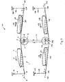
- FIGs. 1 and 2 show an apparatus 1 for cultivating cells in a container 2 utilizing wave motion of a liquid medium 3 comprising a cell culture in the container.
- the container 2 is a plastic bag having a single hollow interior chamber. The plastic bag is secured to a platform 7 of the apparatus 1.
- other types of containers and other types of retaining means for retaining the container may also be applied
- the apparatus comprises a driving mechanism for swivelling the platform 7, and hence the bag 2, with respect to a substantially horizontal pivot axis 5.
- the pivot axis 5 is the central axis of a hinge joint between the platform 7 and a rotating beam 8 of the apparatus 1.
- Many types of hinge connections between the platform and the rotating beam 8 can be applied.
- the rotating beam 8 is driven by a motor 4 to rotate around a rotation axis 9 which is distant and parallel to the pivot axis 5.
- the driving mechanism is arranged to swivel the bag 2 such that during said swivelling, the pivot axis 5 follows a cyclical closed-loop path 6.
- the closed-loop path 6 has a circular shape, which is simple to realize. However, by choosing different configurations of the driving mechanism, other shapes of closed-loop paths can be applied as well.
- the platform 7 is furthermore swivelling with respect to a second pivot axis 15 which is distant and parallel to the pivot axis 5.
- the second pivot axis 15 is the central axis of a second hinge joint between the platform 7 and a second beam 18 of the apparatus 1.
- the second beam 18 is rotatable with respect to a second rotation axis 19 which is distant and parallel to the second pivot axis 15, such that the second pivot axis 15 of the second beam 18 is free to move back and forth along an arched path 16.
- the orientation of the first rotation axis 9 relative to the orientation of the second rotation axis 9 remains the same during the movement of the platform.
- Figs. 2A-2D show four different stages during the thus obtained movement of the bag 2.
- the closed-loop path 6 lies in a plane transverse to the pivot axis 5. This is favourable because then the movement vector of the pivot axis along such closed-loop path is in the same plane as the movement vector V of the waves, which turns out to be very efficient. High efficiency is also achieved when at least the projection of the closed-loop path onto a plane transverse to the pivot axis has a closed-loop shape.
- closed-loop paths can be applied with any type of shape in space, for example a closed-loop path in a horizontal plane through the pivot axis or a closed-loop path in a vertical plane through the pivot axis.
- FIG. 3 shows an example of a second embodiment of an apparatus according to the invention.
- the shown apparatus is an apparatus 101 for cultivating cells in a multiplicity of containers utilizing wave motion of a liquid media.
- the apparatus 101 comprises an apparatus 1 of the type shown in Figs. 1 and 2.
- This apparatus 1 is shown in the upper left part of Fig. 3, wherein the same reference numerals are used as in Figs. 1 and 2.
- the apparatus 101 is furthermore arranged for cultivating cells in a co-swivelling container 2A, shown in the upper right part of Fig. 3.
- the driving mechanism is arranged to swivel both the container 2 and the co-swivelling container 2A simultaneously. In the shown example, this is realized in the following manner.
- the co-swivelling bag 2 is retained by a platform 7A, similar to the platform 7 of apparatus 1.
- This platform 7A has a hinge joint with the rotating beam 8 of apparatus 1, this hinge joint having the pivot axis 5 as central axis.
- the platform 7A is furthermore swivelling with respect to a pivot axis 15A which is distant and parallel to the pivot axis 5.
- the pivot axis 15A is the central axis of a hinge joint between the platform 7A and a beam 18A.
- the beam 18A is rotatable with respect to a rotation axis 19A which is distant and parallel to the pivot axis 15A, such that the pivot axis 15A of the beam 18A is free to move back and forth along an arched path 16A.
- the respective orientation of the rotation axes 9 and 19A remains the same during the movement of the platform 7A.
- Cultivating cells in a multiplicity of co-swivelling containers simultaneously driven by a joint driving mechanism of an apparatus offers a number of advantages. For instance, when compared to the use of a larger size single container, once culturing conditions are established for one container, there is no need for additional experimenting to scale up the cell culture volume. All that is required is placing several containers on the apparatus. Furthermore, cell culturing in parallel yet separate containers reduces the risk of culture failures, e.g. by infection or contamination. This contributes to the reliability of the culturing system.
- Fig. 3 the bag 2 and the co-swivelling bag 2A are positioned side by side as seen in a plane transverse to the pivot axis 5.
- Other types of side by side positions are also possible.
- a side by side positioning as seen in a vertical plane through the pivot axis 5 is possible, wherein co-swivelling platforms are swivelling relative to the pivot axis 5 at different axial positions along the pivot axis 5.
- the apparatus 101 is furthermore arranged for cultivating cells in two co-swivelling containers 2B, shown in the lower left and lower right parts of Fig. 3, respectively.
- the configuration of the apparatus 101 shown in the upper left and upper right parts of Fig. 3 is repeated in the lower left and lower right parts of Fig. 3.
- Corresponding parts of the corresponding configurations are denoted by corresponding reference numerals, wherein the affix B is added to the reference numerals, respectively is replacing the affix A of the reference numeral in the upper parts of Fig. 3.
- the driving mechanism is arranged to swivel both the containers 2 and 2A and the two containers 2B simultaneously, for example by means of a driving belt 20 as shown.
- the apparatus 101 is arranged to perform the simultaneous swivelling in a condition in which different swivelling containers are positioned above one another.
- An advantage of placing a multiplicity of containers above one another is that it reduces costly plant space; the entire assembly of apparatus and containers occupies a much smaller surface area as compared to containers placed adjacent to each other in the horizontal plane. This allows for easy containment of the assembly in a cultivating room.
- the swivelling direction of the bag 2 relative to the joint pivot axis 5 is opposite to the swivelling direction of the co-swivelling container 2A relative to the joint pivot axis 5.
- FIGs. 4-6 show an example of a third embodiment of an apparatus according to the invention.
- the figures show an apparatus 51 for cultivating cells in a container utilizing wave motion of a liquid medium in the container.
- the container is not shown.
- the container can for example be a plastic bag having a single hollow interior chamber. Such a bag can be secured to the shown platform 57 of the apparatus 51.
- the apparatus 51 comprises a driving mechanism for swivelling the container with respect to a substantially horizontal pivot axis 55.
- the pivot axis 55 is the central axis of a hinge connection between the platform 57 and a rotating beam 58 of the apparatus 51.
- the rotating beam 58 is driven by a motor 54 to rotate around a rotation axis 59 which is distant and parallel to the pivot axis 55.
- the driving mechanism is arranged to swivel the container such that during said swivelling, the pivot axis 55 follows a cyclical closed-loop path 56.
- the driving mechanism of the apparatus 51 is furthermore arranged to swivel the container such that during said swivelling the container carries out a second swivelling with respect to a second pivot axis 65 which is distant and parallel to the substantially horizontal pivot axis 55, during which second swivelling the second pivot axis 65 follows a second cyclical closed-loop path 66.
- the second pivot axis 65 is the central axis of a second hinge connection between the platform 57 and a scissor-beam assembly.
- the scissor-beam assembly comprises a second beam 68 and a third beam 78 which beams are interconnected via a hinge axis 77.
- the second beam 68 is rotatable with respect to a second rotation axis 69 which is distant and parallel to the second pivot axis 65.
- the rotation of the second beam 68 is driven by a motor 64.
- the hinge axis 77 of the scissor-beam assembly follows a cyclical closed-loop path 76 which has circular shape.
- Figs. 4 and 5 show the second cyclical closed-loop path 66 which will be followed by the second pivot axis 65 when the first and second beams 58 and 68 are driven with the same rotation speed, however in opposite rotation directions.
- first rotation axis 59 relative to the orientation of the second rotation axis 69 remains the same during the movement of the platform 57. It is remarked that, instead of using two motors 54 and 64, also one motor could be applied driving the rotation of both the first beam 58 and the second beam 68, by utilizing suitable transmission means.
- An advantage of such an apparatus based upon such second swivelling with respect to a second pivot axis 65 which is distant and parallel to the substantially horizontal pivot axis 55, is that in operation of the driving mechanism a wide range of varying slopes of the container can be obtained with only little vertical space requirement by the driving mechanism.
- only short lengths of the first and second beams 58 and 68 suffice to create such wide slope range.
- the container is a disposable container.
- the cell culture can be simply harvested from the container and the used container is discarded.
- a new container, provided with a new cell culture, can be immediately placed on the platform of the apparatus.
- the container is a pre-sterilized disposable container since this eliminates labour intensive cleaning, sterilization and associated validation.
- Such containers are known in the art.
- US6,190,913 B1 discloses a pre-sterilized flexible plastic bag in which cells are cultivated. These single-use bioreactors are commercially available from Wave Biotech LLC, New Jersey ,USA.
- the container may be provided with additional means, such as means which facilitate the addition or removal of a substance, e.g. liquid medium or a sample, from the container (see for example US2003/0036192 ).
- the invention also relates to a flexible or adjustable cell culturing container.
- a cell culture by introducing an inoculation cell culture in a relatively small container comprising a relatively small volume of growth medium, like 200 milliliter, such that the cell density is within an optimal range for cell replication.
- the starting culture is expanded by a step-wise transfer to containers of increasing size, for example up to a cell culture volume of 20 liters or even more, ensuring that the cell density is maintained within the required range.
- Presently known containers do not allow to perform the cell culture expansion from a small inoculation culture to a large 'working' culture in one single container.
- the dimensions of a container that can accommodate the volume of a working culture, e.g.
- the invention provides a "flexible" container that allows for modulating or adjusting the effective volume of the container during cell culturing.
- the term "effective volume” is meant to indicate the volume of the container which can be occupied by the cell culture. Modulating or restraining the effective volume involves in particular the restraining of one or more flexible walls of the container at the onset of the culturing process, while gradually or stepwise releasing the restrain along with expansion of the cell culture volume.
- adjusting the effective volume can also involve reducing the effective volume of the container.
- the initial effective volume is about 10% of the maximal volume of the container.
- the container preferably has one or more flexible walls. It is for example a plastic bag whose side walls can be pushed downwards or towards each other by external means, like clamps, such that the volume of the bag is reduced.
- Modulating the effective volume of the container during the cell cultivation process by changing the position of at least a flexible part of the container wall can be applied during cell cultivating methods wherein the container is moved in ways as explained above.
- said modulating can also be favourably applied for other cell culturing methods, wherein the container is moved in other ways, or wherein the container is not moved at all.
Landscapes
- Chemical & Material Sciences (AREA)
- Health & Medical Sciences (AREA)
- Engineering & Computer Science (AREA)
- Life Sciences & Earth Sciences (AREA)
- Wood Science & Technology (AREA)
- Organic Chemistry (AREA)
- Bioinformatics & Cheminformatics (AREA)
- Zoology (AREA)
- Genetics & Genomics (AREA)
- Biotechnology (AREA)
- Biomedical Technology (AREA)
- Microbiology (AREA)
- Biochemistry (AREA)
- General Engineering & Computer Science (AREA)
- General Health & Medical Sciences (AREA)
- Sustainable Development (AREA)
- Clinical Laboratory Science (AREA)
- Chemical Kinetics & Catalysis (AREA)
- Analytical Chemistry (AREA)
- Mechanical Engineering (AREA)
- Cell Biology (AREA)
- Apparatus Associated With Microorganisms And Enzymes (AREA)
Abstract
A method for cultivating cells utilizing wave motion comprises the steps of:
- providing a container (2; 2A; 2B);
- introducing a gas containing oxygen, a liquid medium (3) and a cell culture into the container;
- moving the container such that the container swivels with respect to a substantially horizontal pivot axis (5; 5B; 55) to thereby induce a wave motion to the liquid medium (3) in the container, which wave motion contributes to the necessary oxygen transfer and mixing required for cell growth.
During said swivelling of the container said pivot axis (5; 5B; 55) follows a cyclical closed-loop path (6; 6B; 56).


Description
- The invention relates to the field of biotechnology and industrial scale cell culturing. In particular, it relates to a method and an apparatus for cultivating cells utilizing wave motion.
- Such a method and such an apparatus are known from
US 6,190,913 B1 . This known technique employs a pre-sterilized flexible plastic bag in which cells are cultivated. The bag is partially filled with growth media and the remainder of the bag is continuously purged with air or other oxygen-rich gas. The bag is secured to a rocking platform that is rocked to and fro about one horizontal axis by the alternate actuation of pneumatic pistons. The rocking motion promotes wave formation in the bag which provides liquid mixing and enhances oxygen transfer from the headspace gas to the liquid phase where it is essential for cell growth and metabolism. - It is an object of the invention to further improve cell growth and productivity in the cultivating of cells utilizing wave motion. Inter alia, it is an object to provide a cell culturing system which is suitable for industrial scale-up.
- According to the present invention, this object is achieved by providing a method according to
claim 1. The invention may also be embodied in an apparatus according toclaim 8 and in an assembly according toclaim 16. - The combination of the swivelling movement of the container with respect to the pivot axis and the cyclical movement of the pivot axis along the closed-loop path induces a wave motion of the liquid medium in the container, which wave motion results into enhanced oxygen transfer and liquid mixing. The wave motion can be optimized for a given cell culture to provide sufficient oxygen transfer for high-density cell culture without excessive foaming or shear damage. No mechanical mixing is required. Thus, an improved cell growth and productivity, e.g. of a recombinantly produced protein, can be achieved.
- Particular embodiments of the invention are set forth in the dependent claims.
- Further features, effects and details of embodiments of the invention are described below with reference to the accompanying schematical drawings.
- Fig. 1 shows in side view an example of an embodiment of an apparatus according to the invention.
- Figs. 2A-2D show the example of Fig. 1 at different stages during the movement of a container.
- Fig. 3 shows in side view an example of a second embodiment of an apparatus according to the invention.
- Fig. 4 shows in side view an example of a third embodiment of an apparatus according to the invention.
- Figs. 5A-5H show the example of Fig. 4 at different stages during the movement of a container.
- Fig. 6 shows the example of Figs. 4 and 5 in a perspective view.
- Reference is first made to Figs. 1 and 2. These figures show an
apparatus 1 for cultivating cells in acontainer 2 utilizing wave motion of aliquid medium 3 comprising a cell culture in the container. In the shown example, thecontainer 2 is a plastic bag having a single hollow interior chamber. The plastic bag is secured to aplatform 7 of theapparatus 1. However, other types of containers and other types of retaining means for retaining the container may also be applied - The apparatus comprises a driving mechanism for swivelling the
platform 7, and hence thebag 2, with respect to a substantiallyhorizontal pivot axis 5. In the example, thepivot axis 5 is the central axis of a hinge joint between theplatform 7 and arotating beam 8 of theapparatus 1. Many types of hinge connections between the platform and the rotatingbeam 8 can be applied. The rotatingbeam 8 is driven by amotor 4 to rotate around a rotation axis 9 which is distant and parallel to thepivot axis 5. The driving mechanism is arranged to swivel thebag 2 such that during said swivelling, thepivot axis 5 follows a cyclical closed-loop path 6. The closed-loop path 6 has a circular shape, which is simple to realize. However, by choosing different configurations of the driving mechanism, other shapes of closed-loop paths can be applied as well. - In the example, the
platform 7 is furthermore swivelling with respect to asecond pivot axis 15 which is distant and parallel to thepivot axis 5. Thesecond pivot axis 15 is the central axis of a second hinge joint between theplatform 7 and asecond beam 18 of theapparatus 1. Thesecond beam 18 is rotatable with respect to asecond rotation axis 19 which is distant and parallel to thesecond pivot axis 15, such that thesecond pivot axis 15 of thesecond beam 18 is free to move back and forth along anarched path 16. The orientation of the first rotation axis 9 relative to the orientation of the second rotation axis 9 remains the same during the movement of the platform. - Figs. 2A-2D show four different stages during the thus obtained movement of the
bag 2. - In the example, the closed-
loop path 6 lies in a plane transverse to thepivot axis 5. This is favourable because then the movement vector of the pivot axis along such closed-loop path is in the same plane as the movement vector V of the waves, which turns out to be very efficient. High efficiency is also achieved when at least the projection of the closed-loop path onto a plane transverse to the pivot axis has a closed-loop shape. - However, closed-loop paths can be applied with any type of shape in space, for example a closed-loop path in a horizontal plane through the pivot axis or a closed-loop path in a vertical plane through the pivot axis.
- Reference is now made to Fig. 3, which shows an example of a second embodiment of an apparatus according to the invention. The shown apparatus is an
apparatus 101 for cultivating cells in a multiplicity of containers utilizing wave motion of a liquid media. Theapparatus 101 comprises anapparatus 1 of the type shown in Figs. 1 and 2. Thisapparatus 1 is shown in the upper left part of Fig. 3, wherein the same reference numerals are used as in Figs. 1 and 2. Theapparatus 101 is furthermore arranged for cultivating cells in aco-swivelling container 2A, shown in the upper right part of Fig. 3. For that purpose, the driving mechanism is arranged to swivel both thecontainer 2 and theco-swivelling container 2A simultaneously. In the shown example, this is realized in the following manner. - The
co-swivelling bag 2 is retained by aplatform 7A, similar to theplatform 7 ofapparatus 1. Thisplatform 7A has a hinge joint with therotating beam 8 ofapparatus 1, this hinge joint having thepivot axis 5 as central axis. Theplatform 7A is furthermore swivelling with respect to apivot axis 15A which is distant and parallel to thepivot axis 5. Thepivot axis 15A is the central axis of a hinge joint between theplatform 7A and abeam 18A. Thebeam 18A is rotatable with respect to a rotation axis 19A which is distant and parallel to thepivot axis 15A, such that thepivot axis 15A of thebeam 18A is free to move back and forth along an arched path 16A. The respective orientation of the rotation axes 9 and 19A remains the same during the movement of theplatform 7A. - Cultivating cells in a multiplicity of co-swivelling containers simultaneously driven by a joint driving mechanism of an apparatus, offers a number of advantages. For instance, when compared to the use of a larger size single container, once culturing conditions are established for one container, there is no need for additional experimenting to scale up the cell culture volume. All that is required is placing several containers on the apparatus. Furthermore, cell culturing in parallel yet separate containers reduces the risk of culture failures, e.g. by infection or contamination. This contributes to the reliability of the culturing system.
- In Fig. 3 the
bag 2 and theco-swivelling bag 2A are positioned side by side as seen in a plane transverse to thepivot axis 5. Other types of side by side positions are also possible. For example, a side by side positioning as seen in a vertical plane through thepivot axis 5 is possible, wherein co-swivelling platforms are swivelling relative to thepivot axis 5 at different axial positions along thepivot axis 5. - The
apparatus 101 is furthermore arranged for cultivating cells in twoco-swivelling containers 2B, shown in the lower left and lower right parts of Fig. 3, respectively. In fact the configuration of theapparatus 101 shown in the upper left and upper right parts of Fig. 3 is repeated in the lower left and lower right parts of Fig. 3. Corresponding parts of the corresponding configurations are denoted by corresponding reference numerals, wherein the affix B is added to the reference numerals, respectively is replacing the affix A of the reference numeral in the upper parts of Fig. 3. In the shown example, this is realized in that the driving mechanism is arranged to swivel both thecontainers containers 2B simultaneously, for example by means of a drivingbelt 20 as shown. Thus, theapparatus 101 is arranged to perform the simultaneous swivelling in a condition in which different swivelling containers are positioned above one another. An advantage of placing a multiplicity of containers above one another is that it reduces costly plant space; the entire assembly of apparatus and containers occupies a much smaller surface area as compared to containers placed adjacent to each other in the horizontal plane. This allows for easy containment of the assembly in a cultivating room. - In the example of Fig. 3, the swivelling direction of the
bag 2 relative to thejoint pivot axis 5 is opposite to the swivelling direction of theco-swivelling container 2A relative to thejoint pivot axis 5. This results into the movement vector V of the waves in thebag 2 and the movement vector VA of the waves in thebag 2A having opposite horizontal components. This turns out to be favourable with respect to energy economy and vibrations of the apparatus in operation. - This also holds for the lower configuration shown in Fig. 3. That is, the swivelling directions of the two shown
bags 2B relative to theirjoint pivot axis 5B are mutually opposite, resulting into movement vectors VB of the waves in thebags 2B having mutually opposite horizontal components. The thus obtained advantage with respect to energy economy and vibrations is enhanced by arranging the apparatus such that the movement vector VB in the lower left part of Fig. 3 has a horizontal component which is opposite to the horizontal component V. - The combined effect of both side by side positioning and positioning above one another of containers, allows two dimensional and three dimensional arrangement of containers in one apparatus. This is favourable with respect to space requirements for carrying out methods for cell cultivation. It also is favourable with respect to costs of apparatuses for cell cultivation, because a single driving structure can be arranged to drive the swivelling motion of many containers.
- Reference is now made to Figs. 4-6. These figures show an example of a third embodiment of an apparatus according to the invention. The figures show an
apparatus 51 for cultivating cells in a container utilizing wave motion of a liquid medium in the container. For reasons of clarity, the container is not shown. Similar to the examples shown in Figs.1-3, the container can for example be a plastic bag having a single hollow interior chamber. Such a bag can be secured to the shownplatform 57 of theapparatus 51. - Also similar to the examples shown in Figs.1-3, the
apparatus 51 comprises a driving mechanism for swivelling the container with respect to a substantiallyhorizontal pivot axis 55. In the example, thepivot axis 55 is the central axis of a hinge connection between theplatform 57 and arotating beam 58 of theapparatus 51. Therotating beam 58 is driven by amotor 54 to rotate around arotation axis 59 which is distant and parallel to thepivot axis 55. The driving mechanism is arranged to swivel the container such that during said swivelling, thepivot axis 55 follows a cyclical closed-loop path 56. - The driving mechanism of the
apparatus 51 is furthermore arranged to swivel the container such that during said swivelling the container carries out a second swivelling with respect to asecond pivot axis 65 which is distant and parallel to the substantiallyhorizontal pivot axis 55, during which second swivelling thesecond pivot axis 65 follows a second cyclical closed-loop path 66. Thesecond pivot axis 65 is the central axis of a second hinge connection between theplatform 57 and a scissor-beam assembly. In the example, the scissor-beam assembly comprises asecond beam 68 and athird beam 78 which beams are interconnected via ahinge axis 77. Thesecond beam 68 is rotatable with respect to a second rotation axis 69 which is distant and parallel to thesecond pivot axis 65. The rotation of thesecond beam 68 is driven by amotor 64. During the rotation of thesecond beam 68, thehinge axis 77 of the scissor-beam assembly follows a cyclical closed-loop path 76 which has circular shape. As an example, Figs. 4 and 5 show the second cyclical closed-loop path 66 which will be followed by thesecond pivot axis 65 when the first andsecond beams first rotation axis 59 relative to the orientation of the second rotation axis 69 remains the same during the movement of theplatform 57. It is remarked that, instead of using twomotors first beam 58 and thesecond beam 68, by utilizing suitable transmission means. - An advantage of such an apparatus based upon such second swivelling with respect to a
second pivot axis 65 which is distant and parallel to the substantiallyhorizontal pivot axis 55, is that in operation of the driving mechanism a wide range of varying slopes of the container can be obtained with only little vertical space requirement by the driving mechanism. In the example of Figs. 4-6, only short lengths of the first andsecond beams - As said, the invention can be practised using many types of containers. In one embodiment, the container is a disposable container. On completion of the cell cultivation, the cell culture can be simply harvested from the container and the used container is discarded. A new container, provided with a new cell culture, can be immediately placed on the platform of the apparatus. In a preferred embodiment, the container is a pre-sterilized disposable container since this eliminates labour intensive cleaning, sterilization and associated validation. Such containers are known in the art. For example,
US6,190,913 B1 discloses a pre-sterilized flexible plastic bag in which cells are cultivated. These single-use bioreactors are commercially available from Wave Biotech LLC, New Jersey ,USA. The container may be provided with additional means, such as means which facilitate the addition or removal of a substance, e.g. liquid medium or a sample, from the container (see for exampleUS2003/0036192 ). - The invention also relates to a flexible or adjustable cell culturing container. At present, it is common practice to start a cell culture by introducing an inoculation cell culture in a relatively small container comprising a relatively small volume of growth medium, like 200 milliliter, such that the cell density is within an optimal range for cell replication. Subsequently, the starting culture is expanded by a step-wise transfer to containers of increasing size, for example up to a cell culture volume of 20 liters or even more, ensuring that the cell density is maintained within the required range. Presently known containers do not allow to perform the cell culture expansion from a small inoculation culture to a large 'working' culture in one single container. The dimensions of a container that can accommodate the volume of a working culture, e.g. 20 or 30 liter culture, are obviously unsuitable to accommodate the initial starting culture. Each step of the step-wise transfer of a cell culture to a larger container is a critical procedure as it carries the risk of introducing an infection or a contamination into the culture. Furthermore, it is very labour-intensive. To overcome these problems, the invention provides a "flexible" container that allows for modulating or adjusting the effective volume of the container during cell culturing. The term "effective volume" is meant to indicate the volume of the container which can be occupied by the cell culture. Modulating or restraining the effective volume involves in particular the restraining of one or more flexible walls of the container at the onset of the culturing process, while gradually or stepwise releasing the restrain along with expansion of the cell culture volume. Of course, adjusting the effective volume can also involve reducing the effective volume of the container. As a general rule of thumb, the initial effective volume is about 10% of the maximal volume of the container. Typically, during cell culturing 10 to 80% of the effective volume of the container which, as said, can be adjusted according to the volume of the culture, is filled with liquid medium and cells. There are many ways by which modulation of the effective volume of a container can be realized. The container preferably has one or more flexible walls. It is for example a plastic bag whose side walls can be pushed downwards or towards each other by external means, like clamps, such that the volume of the bag is reduced.
- Modulating the effective volume of the container during the cell cultivation process by changing the position of at least a flexible part of the container wall can be applied during cell cultivating methods wherein the container is moved in ways as explained above. However, said modulating can also be favourably applied for other cell culturing methods, wherein the container is moved in other ways, or wherein the container is not moved at all.
Claims (18)
- A method for cultivating cells utilizing wave motion, comprising the steps of:- providing a container (2; 2A; 2B);- introducing a gas containing oxygen, a liquid medium (3) and a cell culture into the container;- moving the container such that the container swivels with respect to a substantially horizontal pivot axis (5; 5B; 55) to thereby induce a wave motion to the liquid medium (3) in the container, which wave motion contributes to the necessary oxygen transfer and mixing required for cell growth,characterized in that
during said swivelling of the container said pivot axis (5; 5B; 55) follows a cyclical closed-loop path (6; 6B; 56). - A method according to claim 1, wherein the projection of the closed-loop path onto a plane transverse to the pivot axis (5; 5B; 55) has a closed-loop shape.
- A method according to claim 1 or 2, wherein the cyclical closed-loop path (6; 6B; 56) has a circular shape.
- A method according to any of the proceeding claims, wherein- the container (2; 2A; 2B) comprises a pre-sterilized plastic bag having a single hollow interior chamber;- the introducing of the gas, the liquid medium and the cell culture into the container is realized by:- partially filling the bag with the gas to thereby partially inflate the bag;- introducing the liquid medium and the cell culture into the bag, wherein the liquid medium and the cell culture comprise between 10 and 80% of the volume of the bag;- filling the remainder of the bag with the gas such that the bag becomes rigid;- the bag is retained by retaining means (7; 7A; 7B; 57);- the moving of the container (2; 2A; 2B) is realized by moving the retaining means (7; 7A; 7B; 57).
- A method according to any of the proceeding claims, wherein the effective volume of the container (2; 2A; 2B) is modulated during the cell cultivation process.
- A method for cultivating cells, comprising the steps of:- providing a container (2; 2A; 2B) with an at least partly flexible wall;- introducing a gas containing oxygen, a liquid medium (3) and a cell culture into the container; and- modulating the effective volume of the container during the cell cultivation process by changing the position of at least a flexible part of said wall.
- A method according to claim 6, wherein said position changing is achieved by adapting restrainment conditions of the flexible wall part.
- An apparatus for cultivating cells in a container (2; 2A; 2B) utilizing wave motion of a liquid medium in the container, comprising retaining means (7; 7A; 7B; 57) for retaining the container and a driving mechanism for swivelling the container with respect to a substantially horizontal pivot axis (5; 5B; 55), characterized in that the driving mechanism is arranged to swivel the container such that during said swivelling said pivot axis (5; 5B; 55) follows a cyclical closed-loop path (6; 6B; 56).
- An apparatus according to claim 8, arranged for cultivating cells in a co-swivelling container (2A; 2B), the driving mechanism being arranged to swivel both the container and the co-swivelling container simultaneously.
- An apparatus according to claim 9, arranged to perform the simultaneous swivelling in a condition in which the container (2) and the co-swivelling container (2A) are positioned side by side.
- An apparatus according to claim 9, arranged to perform the simultaneous swivelling in a condition in which the container (2) and the co-swivelling container (2B) are positioned above one another.
- An apparatus according to any one of claims 9-11, arranged to perform the simultaneous swivelling such that said substantially horizontal pivot axis (5) functions as joint pivot axis for both the swivelling of the container and the swivelling of the co-swivelling container.
- An apparatus according to any one of claims 12, arranged to perform the simultaneous swivelling such that the swivelling direction of the container relative to the joint pivot axis (5) is opposite to the swivelling direction of the co-swivelling container relative to the joint pivot axis.
- An apparatus according to claim 8, arranged for cultivating cells in at least two co-swivelling containers (2A, 2B), the driving mechanism being arranged to swivel both the container (2) and the at least two co-swivelling containers (2A, 2B) simultaneously in a condition in which the container (2) and at least one (2A) of the at least two co-swivelling containers are positioned side by side and in which the container (2) and at least another one (2B) of the at least two co-swivelling containers are positioned one above the other.
- An apparatus according to any one of claims 8-14,
wherein the driving mechanism is arranged to swivel the container such that during said swivelling the container carries out a second swivelling with respect to a second pivot axis (65) which is distant and parallel to the substantially horizontal pivot axis (55), during which second swivelling the second pivot axis follows a second cyclical closed-loop path (66). - An assembly for cultivating cells, comprising an apparatus (1; 51; 101) according to any one of claims 8-15, and a container (2) for cultivating cells when retained by the retaining means (7; 7A; 7B; 57) of said apparatus.
- Assembly according to claim 16, wherein said container is a disposable container, preferably a pre-sterilized container.
- Assembly according to claim 16 or 17, wherein the container has an at least partly flexible wall, and wherein the assembly further comprises means for modulating the effective volume of the container during the cell cultivation process by changing the position of at least a flexible part of said wall.
Priority Applications (7)
| Application Number | Priority Date | Filing Date | Title |
|---|---|---|---|
| EP05076493A EP1739165A1 (en) | 2005-06-29 | 2005-06-29 | Method and apparatus for cultivating cells utilizing wave motion |
| DK06757812.0T DK1896564T3 (en) | 2005-06-29 | 2006-06-27 | METHOD AND DEVICE FOR CELL CULTURE BY WAVE MOVEMENT |
| ES06757812T ES2833580T3 (en) | 2005-06-29 | 2006-06-27 | Method and apparatus for culturing cells using wave motion |
| EP06757812.0A EP1896564B1 (en) | 2005-06-29 | 2006-06-27 | Method and apparatus for cultivating cells utilizing wave motion |
| PCT/NL2006/000319 WO2007001173A2 (en) | 2005-06-29 | 2006-06-27 | Method and apparatus for cultivating cells utilizing wave motion |
| PL06757812T PL1896564T3 (en) | 2005-06-29 | 2006-06-27 | Method and apparatus for cultivating cells utilizing wave motion |
| US11/964,874 US8889406B2 (en) | 2005-06-29 | 2007-12-27 | Method and apparatus for cultivating cells utilizing wave motion |
Applications Claiming Priority (1)
| Application Number | Priority Date | Filing Date | Title |
|---|---|---|---|
| EP05076493A EP1739165A1 (en) | 2005-06-29 | 2005-06-29 | Method and apparatus for cultivating cells utilizing wave motion |
Publications (1)
| Publication Number | Publication Date |
|---|---|
| EP1739165A1 true EP1739165A1 (en) | 2007-01-03 |
Family
ID=35520516
Family Applications (2)
| Application Number | Title | Priority Date | Filing Date |
|---|---|---|---|
| EP05076493A Withdrawn EP1739165A1 (en) | 2005-06-29 | 2005-06-29 | Method and apparatus for cultivating cells utilizing wave motion |
| EP06757812.0A Active EP1896564B1 (en) | 2005-06-29 | 2006-06-27 | Method and apparatus for cultivating cells utilizing wave motion |
Family Applications After (1)
| Application Number | Title | Priority Date | Filing Date |
|---|---|---|---|
| EP06757812.0A Active EP1896564B1 (en) | 2005-06-29 | 2006-06-27 | Method and apparatus for cultivating cells utilizing wave motion |
Country Status (6)
| Country | Link |
|---|---|
| US (1) | US8889406B2 (en) |
| EP (2) | EP1739165A1 (en) |
| DK (1) | DK1896564T3 (en) |
| ES (1) | ES2833580T3 (en) |
| PL (1) | PL1896564T3 (en) |
| WO (1) | WO2007001173A2 (en) |
Cited By (5)
| Publication number | Priority date | Publication date | Assignee | Title |
|---|---|---|---|---|
| CN104357324A (en) * | 2014-11-21 | 2015-02-18 | 天津艾赛博生物技术有限公司 | Shaking platform for bioreactor |
| US9090398B2 (en) | 2007-05-04 | 2015-07-28 | Emd Millipore Corporation | Disposable processing bag with alignment feature |
| EP2678416A4 (en) * | 2011-02-23 | 2016-06-08 | Ge Healthcare Bio Sciences Ab | BIOREACTOR COMPRISING AN OSCILLATING DEVICE |
| CN108246183A (en) * | 2018-01-31 | 2018-07-06 | 黑龙江省地质矿产测试应用研究所 | An automatic stirring device for mineral samples with temperature adjustment function |
| EP3845627A1 (en) * | 2019-12-31 | 2021-07-07 | Pall Corporation | Biocontainer assembly for bioprocessing system |
Families Citing this family (38)
| Publication number | Priority date | Publication date | Assignee | Title |
|---|---|---|---|---|
| ATE471755T1 (en) * | 2006-11-14 | 2010-07-15 | Marcel Roell | VIBRATION MIXER |
| JP5023795B2 (en) * | 2007-04-27 | 2012-09-12 | 東洋製罐株式会社 | Cell culture method, cell culture system, and medium adjustment device |
| DE102008015386B4 (en) * | 2008-03-20 | 2015-10-01 | Sartorius Stedim Biotech Gmbh | bioreactor |
| US20110151552A1 (en) * | 2009-12-23 | 2011-06-23 | Ge Healthcare Bio-Sciences Corp. | Bioreactors |
| US11512278B2 (en) | 2010-05-20 | 2022-11-29 | Pond Technologies Inc. | Biomass production |
| US8940520B2 (en) | 2010-05-20 | 2015-01-27 | Pond Biofuels Inc. | Process for growing biomass by modulating inputs to reaction zone based on changes to exhaust supply |
| US8889400B2 (en) | 2010-05-20 | 2014-11-18 | Pond Biofuels Inc. | Diluting exhaust gas being supplied to bioreactor |
| US20120156669A1 (en) | 2010-05-20 | 2012-06-21 | Pond Biofuels Inc. | Biomass Production |
| US8969067B2 (en) | 2010-05-20 | 2015-03-03 | Pond Biofuels Inc. | Process for growing biomass by modulating supply of gas to reaction zone |
| WO2012000502A1 (en) | 2010-07-01 | 2012-01-05 | Stobbe Tech A/S | Rocking device and bioreactor |
| WO2012048276A2 (en) | 2010-10-08 | 2012-04-12 | Caridianbct, Inc. | Customizable methods and systems of growing and harvesting cells in a hollow fiber bioreactor system |
| US20120276633A1 (en) | 2011-04-27 | 2012-11-01 | Pond Biofuels Inc. | Supplying treated exhaust gases for effecting growth of phototrophic biomass |
| US9228166B2 (en) * | 2011-12-20 | 2016-01-05 | Pall Corporation | Rockable biocontainer |
| WO2013103293A1 (en) | 2012-01-04 | 2013-07-11 | Cellution Biotech B.V. | Method and apparatus for cultivating cells |
| EP3241607B1 (en) * | 2012-06-15 | 2019-04-10 | Life Technologies Corporation | Fluid mixing system with tiltable support housing and draining method |
| US9534261B2 (en) | 2012-10-24 | 2017-01-03 | Pond Biofuels Inc. | Recovering off-gas from photobioreactor |
| FR2997703B1 (en) * | 2012-11-07 | 2016-12-30 | Biomerieux Sa | PROCESS FOR TREATING AT LEAST ONE BIOLOGICAL SAMPLE |
| US10260038B2 (en) | 2013-05-10 | 2019-04-16 | Whitehead Institute For Biomedical Research | Protein modification of living cells using sortase |
| WO2015073918A1 (en) | 2013-11-16 | 2015-05-21 | Terumo Bct, Inc. | Expanding cells in a bioreactor |
| EP3115450A4 (en) * | 2014-03-07 | 2018-03-14 | Toyo Seikan Group Holdings, Ltd. | Cell culture method and cell culture device |
| WO2015148704A1 (en) | 2014-03-25 | 2015-10-01 | Terumo Bct, Inc. | Passive replacement of media |
| WO2016049421A1 (en) | 2014-09-26 | 2016-03-31 | Terumo Bct, Inc. | Scheduled feed |
| US10105664B2 (en) * | 2014-10-30 | 2018-10-23 | Omni International, Inc. | Reciprocating tube-shaking mechanisms for processing a material |
| CN107208028A (en) * | 2015-02-05 | 2017-09-26 | 通用电气公司 | Bioreactor system for cell culture |
| WO2017004592A1 (en) | 2015-07-02 | 2017-01-05 | Terumo Bct, Inc. | Cell growth with mechanical stimuli |
| CN109415696A (en) | 2016-05-25 | 2019-03-01 | 泰尔茂比司特公司 | Cell amplification |
| US11104874B2 (en) | 2016-06-07 | 2021-08-31 | Terumo Bct, Inc. | Coating a bioreactor |
| US11685883B2 (en) | 2016-06-07 | 2023-06-27 | Terumo Bct, Inc. | Methods and systems for coating a cell growth surface |
| EP3512932A1 (en) | 2016-09-14 | 2019-07-24 | VBC Holdings LLC | Systems, apparatus and methods for controlling a movement of a cell culture to optimize cell growth |
| WO2018077995A1 (en) * | 2016-10-31 | 2018-05-03 | General Electric Company | Bioreactor assembly |
| US11624046B2 (en) | 2017-03-31 | 2023-04-11 | Terumo Bct, Inc. | Cell expansion |
| US12234441B2 (en) | 2017-03-31 | 2025-02-25 | Terumo Bct, Inc. | Cell expansion |
| US11629332B2 (en) | 2017-03-31 | 2023-04-18 | Terumo Bct, Inc. | Cell expansion |
| CN107380296B (en) * | 2017-08-25 | 2023-12-26 | 湖南匡楚科技有限公司 | Chemical material mixing device based on crawling robot |
| WO2020064356A1 (en) | 2018-09-27 | 2020-04-02 | Global Life Sciences Solutions Usa Llc | Multicompartment bag for cultivation of cells |
| US11299700B1 (en) | 2021-02-19 | 2022-04-12 | Acequia Biotechnology, Llc | Bioreactor containers and methods of growing hairy roots using the same |
| WO2022204315A1 (en) | 2021-03-23 | 2022-09-29 | Terumo Bct, Inc. | Cell capture and expansion |
| US12152699B2 (en) | 2022-02-28 | 2024-11-26 | Terumo Bct, Inc. | Multiple-tube pinch valve assembly |
Citations (2)
| Publication number | Priority date | Publication date | Assignee | Title |
|---|---|---|---|---|
| US6190913B1 (en) | 1997-08-12 | 2001-02-20 | Vijay Singh | Method for culturing cells using wave-induced agitation |
| US20030036192A1 (en) | 2001-02-15 | 2003-02-20 | Vijay Singh | Disposable perfusion bioreactor for cell culture |
Family Cites Families (6)
| Publication number | Priority date | Publication date | Assignee | Title |
|---|---|---|---|---|
| DE2625208C3 (en) * | 1976-06-04 | 1980-02-21 | Behringwerke Ag, 3550 Marburg | Fermenter |
| US5017490A (en) * | 1989-03-10 | 1991-05-21 | Baxter International Inc. | Method for in vitro reproduction and growth of cells in culture medium |
| US5697701A (en) * | 1996-08-02 | 1997-12-16 | Fokos Designs, Ltd. | Fluid mixer providing gentle agitation |
| WO2001064844A1 (en) * | 2000-03-01 | 2001-09-07 | Clemson University | Intermittent immersion vessel apparatus and process for plant propagation |
| JP4355212B2 (en) * | 2001-12-21 | 2009-10-28 | オーガノジェネシス インコーポレーテッド | Variable volume chamber for cell culture and organ support |
| US7229820B2 (en) * | 2002-06-13 | 2007-06-12 | Wilson Wolf Manufacturing Corporation | Apparatus and method for culturing and preserving tissue constructs |
-
2005
- 2005-06-29 EP EP05076493A patent/EP1739165A1/en not_active Withdrawn
-
2006
- 2006-06-27 WO PCT/NL2006/000319 patent/WO2007001173A2/en active Application Filing
- 2006-06-27 ES ES06757812T patent/ES2833580T3/en active Active
- 2006-06-27 DK DK06757812.0T patent/DK1896564T3/en active
- 2006-06-27 PL PL06757812T patent/PL1896564T3/en unknown
- 2006-06-27 EP EP06757812.0A patent/EP1896564B1/en active Active
-
2007
- 2007-12-27 US US11/964,874 patent/US8889406B2/en active Active
Patent Citations (2)
| Publication number | Priority date | Publication date | Assignee | Title |
|---|---|---|---|---|
| US6190913B1 (en) | 1997-08-12 | 2001-02-20 | Vijay Singh | Method for culturing cells using wave-induced agitation |
| US20030036192A1 (en) | 2001-02-15 | 2003-02-20 | Vijay Singh | Disposable perfusion bioreactor for cell culture |
Cited By (12)
| Publication number | Priority date | Publication date | Assignee | Title |
|---|---|---|---|---|
| US9090398B2 (en) | 2007-05-04 | 2015-07-28 | Emd Millipore Corporation | Disposable processing bag with alignment feature |
| US9187240B2 (en) | 2007-05-04 | 2015-11-17 | Emd Millipore Corporation | Disposable processing bag with alignment feature |
| US9272840B2 (en) | 2007-05-04 | 2016-03-01 | Emd Millipore Corporation | Disposable processing bag with alignment feature |
| US9999568B2 (en) | 2007-05-04 | 2018-06-19 | Emd Millipore Corporation | Disposable processing bag with alignment feature |
| EP2678416A4 (en) * | 2011-02-23 | 2016-06-08 | Ge Healthcare Bio Sciences Ab | BIOREACTOR COMPRISING AN OSCILLATING DEVICE |
| US9738863B2 (en) | 2011-02-23 | 2017-08-22 | Ge Healthcare Bio-Sciences Ab | Bioreactor including a rocking device |
| US11613726B2 (en) | 2011-02-23 | 2023-03-28 | Cytiva Sweden Ab | Bioreactor including a rocking device |
| US11981887B2 (en) | 2011-02-23 | 2024-05-14 | Cytiva Sweden Ab | Bioreactor including a rocking device |
| CN104357324A (en) * | 2014-11-21 | 2015-02-18 | 天津艾赛博生物技术有限公司 | Shaking platform for bioreactor |
| CN104357324B (en) * | 2014-11-21 | 2018-12-07 | 天津艾赛博生物技术有限公司 | A kind of shake platform for bioreactor |
| CN108246183A (en) * | 2018-01-31 | 2018-07-06 | 黑龙江省地质矿产测试应用研究所 | An automatic stirring device for mineral samples with temperature adjustment function |
| EP3845627A1 (en) * | 2019-12-31 | 2021-07-07 | Pall Corporation | Biocontainer assembly for bioprocessing system |
Also Published As
| Publication number | Publication date |
|---|---|
| EP1896564A2 (en) | 2008-03-12 |
| US8889406B2 (en) | 2014-11-18 |
| WO2007001173A2 (en) | 2007-01-04 |
| EP1896564B1 (en) | 2020-09-09 |
| ES2833580T3 (en) | 2021-06-15 |
| WO2007001173A3 (en) | 2007-03-08 |
| PL1896564T3 (en) | 2021-05-04 |
| US20080160597A1 (en) | 2008-07-03 |
| DK1896564T3 (en) | 2020-11-30 |
Similar Documents
| Publication | Publication Date | Title |
|---|---|---|
| EP1739165A1 (en) | Method and apparatus for cultivating cells utilizing wave motion | |
| CN101151361B (en) | Bioreactor assembly comprising at least one tray-like rocking platform | |
| EP1961806B1 (en) | Disposable bioreactor | |
| US6844186B2 (en) | Disposable vessel | |
| CN102365356B (en) | Photosynthetic reactor for cultivating microorganisms, and method for cultivating microorganisms | |
| US20180085722A1 (en) | Disposable bioreactor system | |
| GB2411178A (en) | Apparatus for culturing cells | |
| US20100144022A1 (en) | Continuous Flow Bioreactor | |
| US20060240544A1 (en) | Bioreactor for growing fungus, plant cell, tissue, organ, hairy roots and plantlet | |
| CA2627654A1 (en) | Bioreactor with mixer and sparger | |
| CA2868468A1 (en) | Pivoting pressurized single-use bioreactor | |
| WO2017119513A1 (en) | Rotating culture device and culture vessel for use in rotating culture device | |
| JP2023510857A (en) | Apparatus for processing cells and methods for processing cells | |
| WO2015037468A1 (en) | Culture system and culture method | |
| US20080176315A1 (en) | Apparatus for temporal immersion culture of cells | |
| JP2017195857A (en) | Culture bag and incubator | |
| JP5254319B2 (en) | Multi-axis rotary agitator and method for producing cultured cells using the same | |
| CN101524036A (en) | Filling system of mushroom culture medium | |
| JP6894541B2 (en) | Culture bag and culture equipment | |
| JP5386756B2 (en) | Bioreactors in tissue engineering | |
| US20040109385A1 (en) | Systems and methods for thawing, mixing, and processing biopharmaceutical materials | |
| KR102671332B1 (en) | Bioreactor and cell culture method using same | |
| CN212270135U (en) | Polygonal plastic bag cell reactor of four-rocker shaking table | |
| US20180305650A1 (en) | Culture Bag and Culture Device | |
| JP2023123914A (en) | Microalgae culture device, culture system, and culture method |
Legal Events
| Date | Code | Title | Description |
|---|---|---|---|
| PUAI | Public reference made under article 153(3) epc to a published international application that has entered the european phase |
Free format text: ORIGINAL CODE: 0009012 |
|
| AK | Designated contracting states |
Kind code of ref document: A1 Designated state(s): AT BE BG CH CY CZ DE DK EE ES FI FR GB GR HU IE IS IT LI LT LU MC NL PL PT RO SE SI SK TR |
|
| AX | Request for extension of the european patent |
Extension state: AL BA HR LV MK YU |
|
| AKX | Designation fees paid | ||
| REG | Reference to a national code |
Ref country code: DE Ref legal event code: 8566 |
|
| STAA | Information on the status of an ep patent application or granted ep patent |
Free format text: STATUS: THE APPLICATION IS DEEMED TO BE WITHDRAWN |
|
| 18D | Application deemed to be withdrawn |
Effective date: 20070704 |