EP1739049A2 - Lifting apparatus - Google Patents
Lifting apparatus Download PDFInfo
- Publication number
- EP1739049A2 EP1739049A2 EP06076560A EP06076560A EP1739049A2 EP 1739049 A2 EP1739049 A2 EP 1739049A2 EP 06076560 A EP06076560 A EP 06076560A EP 06076560 A EP06076560 A EP 06076560A EP 1739049 A2 EP1739049 A2 EP 1739049A2
- Authority
- EP
- European Patent Office
- Prior art keywords
- base
- wheels
- raised
- lifting apparatus
- allow
- Prior art date
- Legal status (The legal status is an assumption and is not a legal conclusion. Google has not performed a legal analysis and makes no representation as to the accuracy of the status listed.)
- Withdrawn
Links
Images


Classifications
-
- B—PERFORMING OPERATIONS; TRANSPORTING
- B66—HOISTING; LIFTING; HAULING
- B66F—HOISTING, LIFTING, HAULING OR PUSHING, NOT OTHERWISE PROVIDED FOR, e.g. DEVICES WHICH APPLY A LIFTING OR PUSHING FORCE DIRECTLY TO THE SURFACE OF A LOAD
- B66F7/00—Lifting frames, e.g. for lifting vehicles; Platform lifts
- B66F7/06—Lifting frames, e.g. for lifting vehicles; Platform lifts with platforms supported by levers for vertical movement
- B66F7/0625—Lifting frames, e.g. for lifting vehicles; Platform lifts with platforms supported by levers for vertical movement with wheels for moving around the floor
-
- B—PERFORMING OPERATIONS; TRANSPORTING
- B66—HOISTING; LIFTING; HAULING
- B66F—HOISTING, LIFTING, HAULING OR PUSHING, NOT OTHERWISE PROVIDED FOR, e.g. DEVICES WHICH APPLY A LIFTING OR PUSHING FORCE DIRECTLY TO THE SURFACE OF A LOAD
- B66F7/00—Lifting frames, e.g. for lifting vehicles; Platform lifts
- B66F7/02—Lifting frames, e.g. for lifting vehicles; Platform lifts with platforms suspended from ropes, cables, or chains or screws and movable along pillars
-
- B—PERFORMING OPERATIONS; TRANSPORTING
- B66—HOISTING; LIFTING; HAULING
- B66F—HOISTING, LIFTING, HAULING OR PUSHING, NOT OTHERWISE PROVIDED FOR, e.g. DEVICES WHICH APPLY A LIFTING OR PUSHING FORCE DIRECTLY TO THE SURFACE OF A LOAD
- B66F7/00—Lifting frames, e.g. for lifting vehicles; Platform lifts
- B66F7/06—Lifting frames, e.g. for lifting vehicles; Platform lifts with platforms supported by levers for vertical movement
- B66F7/065—Scissor linkages, i.e. X-configuration
Definitions
- the invention which is the subject of this application relates to apparatus for lifting articles or persons between lowered and raised positions.
- the apparatus is provided in a lowered position to allow articles to be placed on or rolled onto a base from a surface and then raised or lowered on said base to a level to allow access of the article or person to another surface for example, such as would be used for the loading and unloading of articles onto the storage area of a lorry or trailer, or person onto rail carriages, buses or the like.
- lifting apparatus there are many different known forms of lifting apparatus, one of which is described in the Applicant's co-pending application No. WO 9711023 .
- a lifting base which is movable between raised and lowered positions and, when in the lowered position, the base can be powered downwardly to move in relation to a supporting frame which is positioned to lie close to and parallel with the surface.
- the base can then be further powered downwardly towards the surface and, as it does so, contacts with the surface and causes the frame to be released from the surface.
- the base is typically provided with wheels or rollers protruding underneath the same such that when the base is powered down towards the surface, it, and the wheels and rollers move through the aperture defined by the frame and the wheels or rollers contact with the surface.
- the apparatus In this position, the apparatus is movable about the surface to the required location.
- the support frame When the base is raised, the support frame returns to contact the surface and so, when the base is being raised or lowered the frame is held in constant, fixed position on the surface.
- This arrangement is particularly suited for the loading of vehicles with goods from and into warehouses or delivery points and where the base is required to carry a considerable number of articles all of which are to be stored and moved into the same location.
- one problem of the disclosed apparatus is that the wheels or rollers protrude below the base to move the apparatus, the base is raised from the floor even when in a fully lowered position and this can make it difficult for items such as trolleys, wheelchairs and the like to be rolled onto the base.
- Another feature which can be a problem in certain uses is that it is not possible to have the apparatus movable when the base is in a raised position as the wheels or rollers are mounted on the base itself. This can be inconvenient when the apparatus is used for more frequent loading and unloading of items such as, for example, persons on wheelchairs.
- the aim of the present invention is to provide apparatus which has improved utility to suit specific requirements and uses of the same.
- lifting apparatus comprising a base which is movable between raised and lowered positions, a support frame in relation to which said base is movable, guide means which guide the movement of the base between raised and lowered positions, power means which allow the base to be moved between positions, and wheels or rollers which allow the apparatus to be moved along a surface, said wheels or rollers and frame respectively movable between an in-use position in which the wheels or rollers contact a surface and an out of use position in which the support frame contacts the surface, said wheels or rollers capable of being provided in the in-use position regardless of the position of the base relative to the support frame and characterised in that the support frame can be moved to contact the surface to provide stable support for the apparatus prior to the loading and unloading of goods onto or from the base.
- the wheels or rollers are mounted on a portion of the apparatus and movable with respect to that portion.
- the wheels or rollers are mounted on the support frame and are movable with respect to the support frame.
- the wheels or rollers are mounted on the base and are movable with respect to the base.
- the wheels can be moved between in-use and out of use positions such that in the in-use position the wheels protrude from the bottom of the frame to allow the same to contact with the surface and in the out of use position the wheels are retracted such that the base can be moved closer to the surface than is the case with the wheels in an in-use position and this makes it easier for the moving of goods on and off said base from the surface.
- the wheels can be moved between an in-use position in which the wheels contact the surface and a retracted position with the wheels above the surface and the support frame in contact with the surface. In this position, the lifting apparatus stability is improved and goods can be moved easily from the base to the surface.
- the wheels will be mounted on members which, when in the in-use position, extend outwardly from the frame so that the wheels are positioned outwith the frame when contacting the surface.
- the wheels In the in-use position, the wheels contact the surface and allow the apparatus to be moved across the surface.
- the wheels can be connected to the frame so that the wheels can be moved to the in-use position regardless of the position of the base relative to the frame, and also allow the apparatus to be moved across the surface with the base in a raised position.
- a ramp is provided which can be folded down to improve the rolling of articles to and from the base from the surface.
- the wheels can be provided in connection with the base or alternatively the wheels can be provided in connection with the support frame.
- the invention allows the base to be positioned significantly closer to the surface when the wheels are in an in use position.
- a method of using lifting apparatus for the loading and unloading of goods comprising a base which is movable between raised and lowered positions, a support frame in relation to which said base is movable, guide means which guide the movement of the base between raised and lowered positions, power means which allow the base to be moved between positions, and wheels or rollers which allow the apparatus to be moved along a surface when in an in-use position, characterised in that said method includes the steps of moving the wheels or rollers into an in-use position, moving the apparatus across the surface to a location for loading/unloading of goods to or from the base, bringing the apparatus into a non-movable position by bringing the support frame into contact with the surface to provide a stable support for the apparatus and proceeding to load or unload goods to or from the base, and selectively moving the base to the required height for loading/unloading.
- the power means to move the base between raised and lowered positions, to move the wheels between in-use and out of use positions and/or to move the one or more jacks between a raised position and a retracted position can be provided by manually operated power means or, alternatively, powered drive means can be provided such as electrically or hydraulically powered drives.
- the power means to move the wheels and/or the one or more jacks can be part of the same power means as that used to move the base between raised and lowered positions or, alternatively, separate power means are provided to operate the base, wheels and/or one or more jacks.
- the apparatus is of use for disabled persons and particularly those with wheelchairs to allow movement of said wheelchairs and persons to vehicles, buses or trains.
- the apparatus is provided with a powered drive
- the person in the wheelchair on the base can be provided with control means to allow operation by them of the movement of the apparatus across the surface, thereby allowing increased independence to the disabled user.
- the control means can be permanently attached to the base or to members protruding from the base or may be provided with a flexible connection which allows the control means to be used by a person standing on the base and/or on the surface adjacent the apparatus.
- Another envisaged use is in conjunction with vehicle trailers to allow the loading and unloading of goods to and from the trailers in the warehouses or at delivery points. It is therefore envisaged that each delivery point can be provided with the apparatus according to the invention so that there will be no need for the tail lift apparatus which is conventionally fitted to vehicles which offers significant reductions in cost of the vehicles.
- the apparatus is provided with attachment means to allow the same to be attached to the vehicle trailer to allow the same to be carried with and/or used in conjunction with the trailer in a manner typically as that of for example a tail lift.
- the apparatus has the significant advantage of being disengagable and movable into the delivery area or warehouse with the goods and thus provides the combination of a loading and unloading facility, and goods moving facility which is not possible with conventional tail lifts which are permanently fixed to the vehicles.
- said lifting apparatus comprises a base 4 which is movable between raised and lowered positions as shown in Figures 1A and 1B, a frame 5 in respect of which said base is movable and, mounted on said frame, guide means 6 which control the movement of said base relative to the frame.
- the guide means 6 are provided in a scissor lift arrangement and there is provided a power drive by means of hydraulics and/or electrical drive 8 which causes the movement of the guide means and the base relative to the frame.
- the base 4 is provided with wheels 10 which are mounted on members 11 which are movable between a retracted position as shown in Figures 1A and 1B and an in use position as shown in Figures 1C and 1D.
- the base 4 is provided with a ramp 12 which improves the ease of moving articles onto and off the base, such as trolleys.
- Figure 1A illustrates how, with the wheels retracted, the ramp 12 can be lowered and the base 4 is positioned close to the surface 14 so as to allow the movement of goods onto and off the base.
- Figures 1C and 1D illustrate how, even with the wheels in the in use position, they are positioned to lie outwith the frame 5 and not underneath the base 4 so that the base can still lie relatively closer to the surface than is possible with the apparatus disclosed in the applicant's co-pending application.
- FIGs. 2A-D there is illustrated a further embodiment of the invention, wherein the apparatus is for use by disabled persons in wheelchairs and again comprises base 104, frame 105, guide means 106, drive ram (not shown) and wheels or rollers 110.
- wheels are mounted on the frame 105 via members 111 which allow the same to be moved between a retracted position as shown in Figures 2A and 2B and an in use position whereupon the members extend outwardly and downwardly to allow contact with the surface.
- the wheels are moved between these position by movement of handles 113 between the positions shown in Figures 1A-B and 1C-D.
- the base can be positioned low to the ground when the wheels are in the retracted and in use positions as the same are not positioned underneath the base.
- a ramp 112 can be provided to allow access to and from the base 104 when in a lowered position but it will be seen in Figure 1A that the base 104(shown in broken line 104') lies sufficiently close to the surface to allow a pushchair wheel chair or the like to be moved directly onto the base from the surface 114.
- Said lifting apparatus comprises a base 204 which is movable between raised and lowered positions 206 and 208 respectively, a support frame 210 in respect of which said base is movable and, mounted on said frame, guide means 212 which control the movement of said base relative to the frame.
- the support frame 210 is provided with wheels 214 which are mounted on members 216 and which are movable between a retracted position as shown in Figure 3A to an in use position as shown in Figure 3B.
- the base 204 and/or support frame 210 are provided with ramps 218 which improve the ease of moving articles onto and off the base, such as trolleys.
- Figure 3A illustrates how, with the wheels 214 retracted, the support frame 210 contacts the surface 220 to provide a stable support for the lifting apparatus 202.
- Figure 3B illustrates how, with the wheels 214 in an in-use position, such that the wheels contact the surface 220, the support frame 210 is raised above said surface 220 and the lifting apparatus 202 is movable across the surface.
- the base 204 is movable between raised and lowered positions, 206 and 208 respectively, when the wheels are in a retracted position as shown in Figure 3A and/or when the wheels are in an in-use position as shown in Figure 3B. With the wheels in a retracted position the base 204 can be positioned close to the surface 220 so as to allow the movement of goods onto and off the base.
- a lifting apparatus 222 comprises a base 224 which is movable between raised and lowered positions 226 and 228 respectively, a support frame 230 in respect of which said base is movable and, mounted on said frame and guide means 232 which control the movement of said base relative to the frame.
- the frame 230 is provided with wheels 234 and jacks 236, said jacks being movable between a raised position as shown in Figure 4A and a retracted position as shown in Figure 4B.
- the wheels 234 With the jacks 236 in the raised position, the wheels 234 are raised above a surface 238 and the jacks make contact with the said surface to provide a stable support for the lifting apparatus 222.
- the wheels 234 With the jacks 236 in a retracted position, the wheels 234 are in an in-use position and contact the surface 238 and the lifting apparatus 222 is thus movable across the surface.
- the support frame 230 is raised above the surface 238 and said frame and/or base 224 are provided with ramps 240 to allow movement of goods onto and off said base.
- the lifting apparatus 222 is movable across the surface with the base 224 in either raised or lowered positions, 226 and 228 respectively.
- the lifting apparatus can be provided with attachment means 242 to allow the same to be attached to the opening or openings of a vehicle trailer 244 to allow the same to be used in situ with the trailer in a manner typically as that of for example a tail lift, as illustrated in figures 3A-B and Figures 4A-B.
- a power means to move the base between raised and lowered positions, to move the wheels from an in-use position to a retracted position and/or to move the jacks from an in-use position to a retracted position can be provided by manually operated power means.
- powered drive means can be provided such as electrically or hydraulically powered drives.
- the power means to move the wheels and/or the jacks can be either separate or joined to the power means provided to operate the base between raised and lowered positions.
- the lifting apparatus can be provided with both retractable jacks and retractable wheels.
- Control means can be provided to allow operation and movement of the base between raised and lowered positions by a person on said base.
- the control means can be permanently attached to the base or to members protruding from the base or may be provided with a flexible connection which allows the said control means to be used by a person standing on the base and/or on the surface adjacent the apparatus.
- the apparatus is movable about the surface by means of the wheels 10,110,214,234 when in an in-use position to contact with the surface 114, 14, 220, 238 and also allows the base to be movable to a position closer to the surface than with conventional devices, thereby allowing improved ease of loading and unloading of goods.
- This is not possible with conventional apparatus in which, if the base can be moved close to the surface, such as with tail lifts for vehicles, the apparatus cannot then be moved across the surface or, if it can be moved across the surface, the base is raised considerably higher from the surface which makes the loading and unloading of goods, and particularly goods held in trolleys and the like, problematic.
- the invention of the apparatus as herein described has particular and specific uses, which cannot conveniently be provided by conventional apparatus.
Abstract
Description
- The invention which is the subject of this application relates to apparatus for lifting articles or persons between lowered and raised positions. The apparatus is provided in a lowered position to allow articles to be placed on or rolled onto a base from a surface and then raised or lowered on said base to a level to allow access of the article or person to another surface for example, such as would be used for the loading and unloading of articles onto the storage area of a lorry or trailer, or person onto rail carriages, buses or the like.
- There are many different known forms of lifting apparatus, one of which is described in the Applicant's co-pending application No.
WO 9711023 - However, one problem of the disclosed apparatus is that the wheels or rollers protrude below the base to move the apparatus, the base is raised from the floor even when in a fully lowered position and this can make it difficult for items such as trolleys, wheelchairs and the like to be rolled onto the base. Another feature which can be a problem in certain uses is that it is not possible to have the apparatus movable when the base is in a raised position as the wheels or rollers are mounted on the base itself. This can be inconvenient when the apparatus is used for more frequent loading and unloading of items such as, for example, persons on wheelchairs.
- The aim of the present invention is to provide apparatus which has improved utility to suit specific requirements and uses of the same.
- According to a first aspect of the present invention there is provided lifting apparatus comprising a base which is movable between raised and lowered positions, a support frame in relation to which said base is movable, guide means which guide the movement of the base between raised and lowered positions, power means which allow the base to be moved between positions, and wheels or rollers which allow the apparatus to be moved along a surface, said wheels or rollers and frame respectively movable between an in-use position in which the wheels or rollers contact a surface and an out of use position in which the support frame contacts the surface, said wheels or rollers capable of being provided in the in-use position regardless of the position of the base relative to the support frame and characterised in that the support frame can be moved to contact the surface to provide stable support for the apparatus prior to the loading and unloading of goods onto or from the base.
- Preferably the wheels or rollers are mounted on a portion of the apparatus and movable with respect to that portion.
- In one embodiment the wheels or rollers are mounted on the support frame and are movable with respect to the support frame.
- In an alternative embodiment the wheels or rollers are mounted on the base and are movable with respect to the base.
- In one embodiment the wheels can be moved between in-use and out of use positions such that in the in-use position the wheels protrude from the bottom of the frame to allow the same to contact with the surface and in the out of use position the wheels are retracted such that the base can be moved closer to the surface than is the case with the wheels in an in-use position and this makes it easier for the moving of goods on and off said base from the surface.
- In a further embodiment the wheels can be moved between an in-use position in which the wheels contact the surface and a retracted position with the wheels above the surface and the support frame in contact with the surface. In this position, the lifting apparatus stability is improved and goods can be moved easily from the base to the surface.
- In one embodiment it is envisaged that the wheels will be mounted on members which, when in the in-use position, extend outwardly from the frame so that the wheels are positioned outwith the frame when contacting the surface.
- In the in-use position, the wheels contact the surface and allow the apparatus to be moved across the surface. In one embodiment the wheels can be connected to the frame so that the wheels can be moved to the in-use position regardless of the position of the base relative to the frame, and also allow the apparatus to be moved across the surface with the base in a raised position.
- Typically a ramp is provided which can be folded down to improve the rolling of articles to and from the base from the surface.
- The wheels can be provided in connection with the base or alternatively the wheels can be provided in connection with the support frame.
- The invention allows the base to be positioned significantly closer to the surface when the wheels are in an in use position.
- In a further aspect of the present invention there is provided a method of using lifting apparatus for the loading and unloading of goods, said apparatus comprising a base which is movable between raised and lowered positions, a support frame in relation to which said base is movable, guide means which guide the movement of the base between raised and lowered positions, power means which allow the base to be moved between positions, and wheels or rollers which allow the apparatus to be moved along a surface when in an in-use position, characterised in that said method includes the steps of moving the wheels or rollers into an in-use position, moving the apparatus across the surface to a location for loading/unloading of goods to or from the base, bringing the apparatus into a non-movable position by bringing the support frame into contact with the surface to provide a stable support for the apparatus and proceeding to load or unload goods to or from the base, and selectively moving the base to the required height for loading/unloading.
- In one embodiment the power means to move the base between raised and lowered positions, to move the wheels between in-use and out of use positions and/or to move the one or more jacks between a raised position and a retracted position can be provided by manually operated power means or, alternatively, powered drive means can be provided such as electrically or hydraulically powered drives.
- The power means to move the wheels and/or the one or more jacks can be part of the same power means as that used to move the base between raised and lowered positions or, alternatively, separate power means are provided to operate the base, wheels and/or one or more jacks.
- In one embodiment it is envisaged that the apparatus is of use for disabled persons and particularly those with wheelchairs to allow movement of said wheelchairs and persons to vehicles, buses or trains. When the apparatus is provided with a powered drive, it is of course possible that the person in the wheelchair on the base can be provided with control means to allow operation by them of the movement of the apparatus across the surface, thereby allowing increased independence to the disabled user. The control means can be permanently attached to the base or to members protruding from the base or may be provided with a flexible connection which allows the control means to be used by a person standing on the base and/or on the surface adjacent the apparatus.
- Another envisaged use is in conjunction with vehicle trailers to allow the loading and unloading of goods to and from the trailers in the warehouses or at delivery points. It is therefore envisaged that each delivery point can be provided with the apparatus according to the invention so that there will be no need for the tail lift apparatus which is conventionally fitted to vehicles which offers significant reductions in cost of the vehicles.
- In one alternative embodiment the apparatus is provided with attachment means to allow the same to be attached to the vehicle trailer to allow the same to be carried with and/or used in conjunction with the trailer in a manner typically as that of for example a tail lift. Preferably the apparatus has the significant advantage of being disengagable and movable into the delivery area or warehouse with the goods and thus provides the combination of a loading and unloading facility, and goods moving facility which is not possible with conventional tail lifts which are permanently fixed to the vehicles.
- The invention will now be described with reference to the accompanying drawings, wherein:-
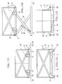
- Figs. 1A-D illustrate the apparatus according to one embodiment of the invention for use with a vehicle storage area;
- Figs. 2A-D illustrate apparatus according to a second embodiment of the invention for use with disabled persons;
- Figures 3A-B illustrates an embodiment of the invention with wheels of the lifting apparatus in retracted and in-use positions; and
- Figures 4A-B illustrates a further embodiment of the invention with jacks of the lifting apparatus in an in-use position and retracted position.
- Referring now the drawings 1A-1D, there is shown a
lifting apparatus 2 according to the invention in one embodiment, said lifting apparatus comprises abase 4 which is movable between raised and lowered positions as shown in Figures 1A and 1B, aframe 5 in respect of which said base is movable and, mounted on said frame, guide means 6 which control the movement of said base relative to the frame. In this case, the guide means 6 are provided in a scissor lift arrangement and there is provided a power drive by means of hydraulics and/or electrical drive 8 which causes the movement of the guide means and the base relative to the frame. In this embodiment thebase 4 is provided withwheels 10 which are mounted onmembers 11 which are movable between a retracted position as shown in Figures 1A and 1B and an in use position as shown in Figures 1C and 1D. Thebase 4 is provided with aramp 12 which improves the ease of moving articles onto and off the base, such as trolleys. - Figure 1A illustrates how, with the wheels retracted, the
ramp 12 can be lowered and thebase 4 is positioned close to thesurface 14 so as to allow the movement of goods onto and off the base. - Figures 1C and 1D illustrate how, even with the wheels in the in use position, they are positioned to lie outwith the
frame 5 and not underneath thebase 4 so that the base can still lie relatively closer to the surface than is possible with the apparatus disclosed in the applicant's co-pending application. - Referring now to Figs. 2A-D, there is illustrated a further embodiment of the invention, wherein the apparatus is for use by disabled persons in wheelchairs and again comprises
base 104,frame 105, guide means 106, drive ram (not shown) and wheels orrollers 110. In this case wheels are mounted on theframe 105 viamembers 111 which allow the same to be moved between a retracted position as shown in Figures 2A and 2B and an in use position whereupon the members extend outwardly and downwardly to allow contact with the surface. In this embodiment the wheels are moved between these position by movement ofhandles 113 between the positions shown in Figures 1A-B and 1C-D. Again it is shown that the base can be positioned low to the ground when the wheels are in the retracted and in use positions as the same are not positioned underneath the base. Aramp 112 can be provided to allow access to and from thebase 104 when in a lowered position but it will be seen in Figure 1A that the base 104(shown in broken line 104') lies sufficiently close to the surface to allow a pushchair wheel chair or the like to be moved directly onto the base from thesurface 114. - Referring now to figures 3A-3B, there is illustrated a
lifting apparatus 202 of a yet further embodiment of the invention. Said lifting apparatus comprises abase 204 which is movable between raised and loweredpositions support frame 210 in respect of which said base is movable and, mounted on said frame, guide means 212 which control the movement of said base relative to the frame. - The
support frame 210 is provided withwheels 214 which are mounted onmembers 216 and which are movable between a retracted position as shown in Figure 3A to an in use position as shown in Figure 3B. Thebase 204 and/orsupport frame 210 are provided withramps 218 which improve the ease of moving articles onto and off the base, such as trolleys. - Figure 3A illustrates how, with the
wheels 214 retracted, thesupport frame 210 contacts thesurface 220 to provide a stable support for thelifting apparatus 202. Figure 3B illustrates how, with thewheels 214 in an in-use position, such that the wheels contact thesurface 220, thesupport frame 210 is raised above saidsurface 220 and thelifting apparatus 202 is movable across the surface. - The
base 204 is movable between raised and lowered positions, 206 and 208 respectively, when the wheels are in a retracted position as shown in Figure 3A and/or when the wheels are in an in-use position as shown in Figure 3B. With the wheels in a retracted position thebase 204 can be positioned close to thesurface 220 so as to allow the movement of goods onto and off the base. - Referring now to Figures 4A-B, there is illustrated a further embodiment of the invention, wherein a
lifting apparatus 222 comprises abase 224 which is movable between raised and loweredpositions support frame 230 in respect of which said base is movable and, mounted on said frame and guide means 232 which control the movement of said base relative to the frame. - The
frame 230 is provided withwheels 234 andjacks 236, said jacks being movable between a raised position as shown in Figure 4A and a retracted position as shown in Figure 4B. With thejacks 236 in the raised position, thewheels 234 are raised above asurface 238 and the jacks make contact with the said surface to provide a stable support for thelifting apparatus 222. With thejacks 236 in a retracted position, thewheels 234 are in an in-use position and contact thesurface 238 and thelifting apparatus 222 is thus movable across the surface. - In both Figures 4A and 4B the
support frame 230 is raised above thesurface 238 and said frame and/orbase 224 are provided withramps 240 to allow movement of goods onto and off said base. Thelifting apparatus 222 is movable across the surface with the base 224 in either raised or lowered positions, 226 and 228 respectively. - The lifting apparatus can be provided with attachment means 242 to allow the same to be attached to the opening or openings of a
vehicle trailer 244 to allow the same to be used in situ with the trailer in a manner typically as that of for example a tail lift, as illustrated in figures 3A-B and Figures 4A-B. - A power means to move the base between raised and lowered positions, to move the wheels from an in-use position to a retracted position and/or to move the jacks from an in-use position to a retracted position can be provided by manually operated power means. Alternatively, powered drive means can be provided such as electrically or hydraulically powered drives.
- The power means to move the wheels and/or the jacks can be either separate or joined to the power means provided to operate the base between raised and lowered positions.
- It will also be appreciated by a person skilled in the art that the lifting apparatus can be provided with both retractable jacks and retractable wheels.
- Control means can be provided to allow operation and movement of the base between raised and lowered positions by a person on said base. The control means can be permanently attached to the base or to members protruding from the base or may be provided with a flexible connection which allows the said control means to be used by a person standing on the base and/or on the surface adjacent the apparatus.
- In use, and in whatever embodiment, the apparatus is movable about the surface by means of the wheels 10,110,214,234 when in an in-use position to contact with the
surface
Claims (14)
- Lifting apparatus (2,202,222) comprising a base (4,104,204,224) which is movable between raised and lowered positions, a support frame (5,105,210,230) in relation to which said base is movable, guide means (6,106,212,232) which guide the movement of the base (4,104,204, 224) between raised and lowered positions, power means (8) which allow the base (4,104,204,224) to be moved between positions, and wheels or rollers (10,110,214,234) which allow the apparatus (2,202,222) to be moved along a surface (238), said wheels or rollers and frame respectively movable between an in-use position in which the wheels or rollers contact a surface and an out of use position in which the support frame contacts the surface, said wheels or rollers capable of being provided in the in-use position regardless of the position of the base relative to the support frame and characterised in that the support frame can be moved to contact the surface to provide stable support for the apparatus prior to the loading and unloading of goods onto or from the base.
- Lifting apparatus according to claim 1 characterised in that the wheels or rollers are movable with respect to the support frame.
- Lifting apparatus according to claim 1 characterised in that the wheels are retracted to an out of use position to allow the base to be moved closer to the surface than would be the case with the wheels in an in-use position.
- Lifting apparatus according to claim 3 characterised in that with the wheels retracted the support frame contacts the surface.
- Lifting apparatus according to claim 3 characterised in that with the wheels retracted the base contacts the surface.
- Lifting apparatus according to any preceding claim characterised in that a ramp is provided which can be moved to allow the rolling of items to and from the base from the surface.
- Lifting apparatus according to any preceding claim characterised in that in an in-use position the wheels protrude from the bottom of the support frame.
- Lifting apparatus according to claim 1 characterised in that the support frame includes one or more jacks and the jacks can move between a raised position with the jacks in contact on the surface and the wheels raised above the surface and a retracted position with the wheels in the in-use position.
- Lifting apparatus according to any preceding claim characterised in that the apparatus is powered by a manually operated power means to move the base, wheels and/or jacks between raised and lowered positions.
- Lifting apparatus according to any preceding claim characterised in that power drive means are provided such as electrical or hydraulic power drives.
- Lifting apparatus according to any preceding claim characterised in that control means are provided to allow operation and movement of the base between raised and lowered positions by a person on said base.
- Lifting apparatus according to claim 11 characterised in that the control means can be permanently attached to the base or to members protruding from the base or may be provided with a flexible connection which allows the said control means to be used by a person standing on the base and/or on the surface adjacent the apparatus.
- Lifting apparatus according to any preceding claim characterised in that the apparatus is provided with attachment means to allow the apparatus to be attached to an opening or openings of a vehicle trailer to allow the same to be used in situ with the trailer as a tail lift.
- A method of using lifting apparatus for the loading and unloading of goods, said apparatus comprising a base (4,104,204,224) which is movable between raised and lowered positions, a support frame (5,105,210,230) in relation to which said base is movable, guide means (6,106,212,232) which guide the movement of the base (4,104,204,224) between raised and lowered positions, power means (8) which allow the base (4,104,204,224) to be moved between positions, and wheels or rollers (10, 110, 214, 234) which allow the apparatus (2,202,222) to be moved along a surface (238) when in an in-use position, characterised in that said method includes the steps of moving the wheels or rollers into an in-use position, moving the apparatus across the surface to a location for loading/unloading of goods to or from the base, bringing the apparatus into a non-movable position by bringing the support frame into contact with the surface to provide a stable support for the apparatus and proceeding to load or unload goods to or from the base, and selectively moving the base to the required height for loading/unloading.
Applications Claiming Priority (2)
| Application Number | Priority Date | Filing Date | Title |
|---|---|---|---|
| GBGB9902565.2A GB9902565D0 (en) | 1999-02-06 | 1999-02-06 | Lifting apparatus |
| EP00300843A EP1026118A3 (en) | 1999-02-06 | 2000-02-03 | Lifting apparatus |
Related Parent Applications (1)
| Application Number | Title | Priority Date | Filing Date |
|---|---|---|---|
| EP00300843A Division EP1026118A3 (en) | 1999-02-06 | 2000-02-03 | Lifting apparatus |
Publications (2)
| Publication Number | Publication Date |
|---|---|
| EP1739049A2 true EP1739049A2 (en) | 2007-01-03 |
| EP1739049A3 EP1739049A3 (en) | 2008-02-20 |
Family
ID=10847158
Family Applications (1)
| Application Number | Title | Priority Date | Filing Date |
|---|---|---|---|
| EP06076560A Withdrawn EP1739049A3 (en) | 1999-02-06 | 2000-02-03 | Lifting apparatus |
Country Status (2)
| Country | Link |
|---|---|
| EP (1) | EP1739049A3 (en) |
| GB (1) | GB9902565D0 (en) |
Cited By (1)
| Publication number | Priority date | Publication date | Assignee | Title |
|---|---|---|---|---|
| ITPI20080132A1 (en) * | 2008-12-19 | 2010-06-20 | Dino Sodini | LIFTING STRUCTURE FOR VEHICLES |
Citations (4)
| Publication number | Priority date | Publication date | Assignee | Title |
|---|---|---|---|---|
| US4488326A (en) * | 1982-09-30 | 1984-12-18 | Autoquip Corporation | Pallet dock lift |
| US5156238A (en) * | 1991-11-18 | 1992-10-20 | Delaware Capital Formation, Inc. | Portable surface lift for a vehicle |
| WO1997011023A1 (en) * | 1995-09-21 | 1997-03-27 | William Mark Adams | Good liffting/moving device |
| US5862884A (en) * | 1995-09-08 | 1999-01-26 | Adaptive Engineering, Ltd. | Lightweight vertical lift device for windy conditions |
-
1999
- 1999-02-06 GB GBGB9902565.2A patent/GB9902565D0/en not_active Ceased
-
2000
- 2000-02-03 EP EP06076560A patent/EP1739049A3/en not_active Withdrawn
Patent Citations (4)
| Publication number | Priority date | Publication date | Assignee | Title |
|---|---|---|---|---|
| US4488326A (en) * | 1982-09-30 | 1984-12-18 | Autoquip Corporation | Pallet dock lift |
| US5156238A (en) * | 1991-11-18 | 1992-10-20 | Delaware Capital Formation, Inc. | Portable surface lift for a vehicle |
| US5862884A (en) * | 1995-09-08 | 1999-01-26 | Adaptive Engineering, Ltd. | Lightweight vertical lift device for windy conditions |
| WO1997011023A1 (en) * | 1995-09-21 | 1997-03-27 | William Mark Adams | Good liffting/moving device |
Cited By (3)
| Publication number | Priority date | Publication date | Assignee | Title |
|---|---|---|---|---|
| ITPI20080132A1 (en) * | 2008-12-19 | 2010-06-20 | Dino Sodini | LIFTING STRUCTURE FOR VEHICLES |
| WO2010070443A2 (en) * | 2008-12-19 | 2010-06-24 | Dino Sodini | Vehicle lifting structure |
| WO2010070443A3 (en) * | 2008-12-19 | 2010-08-19 | Dino Sodini | Vehicle lifting structure |
Also Published As
| Publication number | Publication date |
|---|---|
| EP1739049A3 (en) | 2008-02-20 |
| GB9902565D0 (en) | 1999-03-24 |
Similar Documents
| Publication | Publication Date | Title |
|---|---|---|
| US7351027B2 (en) | Vehicle loader mechanism | |
| US5795123A (en) | Method and a device for transferring load units between two carriers | |
| US10946782B2 (en) | Assistance vehicle tilt lift | |
| EP0629524A1 (en) | Vehicles and vehicle lifts | |
| EP1829815B1 (en) | A forklift truck | |
| US4971510A (en) | Wheelchair passenger device | |
| US9061624B2 (en) | Lift and roll load system | |
| US6234740B1 (en) | Vehicle cargo lift | |
| US6325399B1 (en) | Side lift wheel chairs | |
| US6357990B1 (en) | Truck freight loading wheeled elevator | |
| US6394419B1 (en) | Lifting apparatus | |
| US20050019143A1 (en) | Dolly and trailer jack combination and method of use | |
| US20030147734A1 (en) | Goods handling system | |
| WO1992007746A1 (en) | Self elevating forklift truck | |
| EP0171396B1 (en) | Self loading system | |
| EP1739049A2 (en) | Lifting apparatus | |
| US20070020075A1 (en) | Vehicle passenger lift | |
| US5356262A (en) | High efficiency material handling and transportation system | |
| EP0961750A1 (en) | Good liffting/moving device | |
| US20040091344A1 (en) | Lifting and moving apparatus for a vehicle bed | |
| EP0025768B1 (en) | A transporting system comprising a vehicle with removable container | |
| JPH07172736A (en) | Construction elevator equipped with loading/unloading device | |
| AU750311B2 (en) | Ramp device for transport vehicles | |
| AU580985B2 (en) | Self loading system | |
| EP1498308A1 (en) | Goods handling system |
Legal Events
| Date | Code | Title | Description |
|---|---|---|---|
| PUAI | Public reference made under article 153(3) epc to a published international application that has entered the european phase |
Free format text: ORIGINAL CODE: 0009012 |
|
| 17P | Request for examination filed |
Effective date: 20060811 |
|
| AC | Divisional application: reference to earlier application |
Ref document number: 1026118 Country of ref document: EP Kind code of ref document: P |
|
| AK | Designated contracting states |
Kind code of ref document: A2 Designated state(s): AT BE CH CY DE DK ES FI FR GB GR IE IT LI LU MC NL PT SE |
|
| PUAL | Search report despatched |
Free format text: ORIGINAL CODE: 0009013 |
|
| AK | Designated contracting states |
Kind code of ref document: A3 Designated state(s): AT BE CH CY DE DK ES FI FR GB GR IE IT LI LU MC NL PT SE |
|
| RIC1 | Information provided on ipc code assigned before grant |
Ipc: B66F 7/08 20060101ALI20080117BHEP Ipc: B66F 7/02 20060101ALI20080117BHEP Ipc: B66F 7/06 20060101AFI20080117BHEP |
|
| 17Q | First examination report despatched |
Effective date: 20080506 |
|
| AKX | Designation fees paid |
Designated state(s): AT BE CH CY DE DK ES FI FR GB GR IE IT LI LU MC NL PT SE |
|
| STAA | Information on the status of an ep patent application or granted ep patent |
Free format text: STATUS: THE APPLICATION IS DEEMED TO BE WITHDRAWN |
|
| 18D | Application deemed to be withdrawn |
Effective date: 20080917 |