EP1739043A2 - Paper processing apparatus - Google Patents
Paper processing apparatus Download PDFInfo
- Publication number
- EP1739043A2 EP1739043A2 EP06005073A EP06005073A EP1739043A2 EP 1739043 A2 EP1739043 A2 EP 1739043A2 EP 06005073 A EP06005073 A EP 06005073A EP 06005073 A EP06005073 A EP 06005073A EP 1739043 A2 EP1739043 A2 EP 1739043A2
- Authority
- EP
- European Patent Office
- Prior art keywords
- plate
- paper
- gate
- shaft
- detecting part
- Prior art date
- Legal status (The legal status is an assumption and is not a legal conclusion. Google has not performed a legal analysis and makes no representation as to the accuracy of the status listed.)
- Withdrawn
Links
- 238000012545 processing Methods 0.000 title claims abstract description 21
- 238000001514 detection method Methods 0.000 claims abstract description 11
- 230000007257 malfunction Effects 0.000 description 11
- 238000009825 accumulation Methods 0.000 description 10
- 238000010586 diagram Methods 0.000 description 9
- 238000000034 method Methods 0.000 description 8
- 230000005856 abnormality Effects 0.000 description 5
- 239000000126 substance Substances 0.000 description 5
- 238000012423 maintenance Methods 0.000 description 4
- 230000002159 abnormal effect Effects 0.000 description 2
- 238000003745 diagnosis Methods 0.000 description 2
- 238000012544 monitoring process Methods 0.000 description 2
- 230000003287 optical effect Effects 0.000 description 2
- 238000012790 confirmation Methods 0.000 description 1
- 239000000463 material Substances 0.000 description 1
- 230000000007 visual effect Effects 0.000 description 1
Images



Classifications
-
- B—PERFORMING OPERATIONS; TRANSPORTING
- B65—CONVEYING; PACKING; STORING; HANDLING THIN OR FILAMENTARY MATERIAL
- B65H—HANDLING THIN OR FILAMENTARY MATERIAL, e.g. SHEETS, WEBS, CABLES
- B65H29/00—Delivering or advancing articles from machines; Advancing articles to or into piles
- B65H29/58—Article switches or diverters
-
- B—PERFORMING OPERATIONS; TRANSPORTING
- B65—CONVEYING; PACKING; STORING; HANDLING THIN OR FILAMENTARY MATERIAL
- B65H—HANDLING THIN OR FILAMENTARY MATERIAL, e.g. SHEETS, WEBS, CABLES
- B65H2511/00—Dimensions; Position; Numbers; Identification; Occurrences
- B65H2511/20—Location in space
- B65H2511/21—Angle
- B65H2511/212—Rotary position
-
- B—PERFORMING OPERATIONS; TRANSPORTING
- B65—CONVEYING; PACKING; STORING; HANDLING THIN OR FILAMENTARY MATERIAL
- B65H—HANDLING THIN OR FILAMENTARY MATERIAL, e.g. SHEETS, WEBS, CABLES
- B65H2553/00—Sensing or detecting means
- B65H2553/60—Details of intermediate means between the sensing means and the element to be sensed
Definitions
- the present invention relates to a paper processing apparatus for classifying paper provided with classifying information into accumulation boxes based on the classifying information.
- a paper processing apparatus for processing paper such as a mail automatic reading and sorting machine and a mail aligning and stamping machine comprises about 400 pieces at most of accumulation boxes (hereinafter it will be referred to as a stacker) or accumulation bases.
- a stacker or accumulation bases.
- These stackers and accumulation bases are provided with a diverter gate for sorting the paper. Since the diverter gate is an expendable part, malfunction is increased according to the increase of the number of driving. Therefore, an operation confirming work is indispensable for the stable operation of the apparatus.
- Jpn. Pat. Appln. KOKAI Publication No. 8-91690 discloses a method for automatically monitoring the operation of the diverter gate. According to the method, during the operation of the diverter gate, an image is taken continuously by a ITV camera for detecting the conveyance abnormality according to the change of the paper to be conveyed according to the time.
- the present invention has been achieved for solving the above-mentioned problems, and an object thereof is to provide a paper processing apparatus capable of confirming the malfunction of a gate easily in a short time.
- a paper processing apparatus of the present invention comprises: a rotatable gate which is disposed in a conveyance path for conveying paper, and which converts the conveyance direction of the paper according to classifying information of the paper and sorts the paper, a shaft which rotatably supports the gate, a driver which rotates the gate to the conveyance position according to the classifying information of the paper by rotating the shaft, a plate supported by the shaft so as to be rotated synchronously with the rotation of the gate, a plate detecting part which detects the plate, and a judging part which judges the operation of the gate based on the detection results of the plate detecting part.
- FIGS. 1 and 2 are external appearance diagrams showing an example of a paper processing apparatus of the present invention.
- FIG. 1 is a plan view and FIG. 2 is a front view of FIG. 1.
- a paper processing apparatus 100 comprises a paper supplying and recognizing part 10 for reading and recognizing a conveyance path for conveying paper; and delivery classifying information mentioned on the paper. Furthermore, it comprises a stacker accumulation part 110 for classifying the paper based on the delivery classifying information recognized by the paper supplying and recognizing part 10.
- the image information showing the delivery classifying information can be sent to a video coding system (hereinafter it is referred to as the VCS).
- VCS video coding system
- an operator inputs the delivery classifying information of the paper based on the image information
- a bar code can be printed on the paper by an ink jet printer (hereinafter it is referred to as the IJP) based on the delivery classifying information during the online process.
- IJP ink jet printer
- the paper not recognized can be accumulated on the above-mentioned stacker accumulation part 110 based on the bar code information.
- the paper supplying and recognizing part 10 comprises a supplying part 1 for collectively supplying the paper to be processed, a taking out part 2 for taking out pieces of the paper one by one for sending the same to the conveyance path, a mechanism detecting part 3a, an excluding accumulation part 3b, a pre bar code reading part 4, a character recognizing part 5, delay conveyance paths 6a, 6b, a IJP printing part 7, a verify bar code reading part 8, a stem part 9, and an operate panel 20.
- the apparatus 100 when the apparatus is driven by turning on a starting switch of the operate panel 20 (not shown) with the paper set on the supply part 1, the pieces of paper are taken out from the taking out part 2 one by one.
- the mechanism detecting part 3a can detect paper with a foreign substance introduced such as coins, keys, caps of bottles, and seals, and paper out of a standard size out of the taken out paper and exclude the same to the excluding accumulation part 3b.
- the paper not excluded and to be supplied can be conveyed to the pre bar code reading part 4 and the character recognizing part 5.
- the pre bar code reading part 4 and the character recognizing part 5 read and recognize the delivery classifying information such as the bar code, the postal code and the address, written on the paper.
- the delay conveyance path 6a is a conveyance part for ensuring the time for the recognition in the character recognizing part 5.
- the delay conveyance path 6b is also a conveyance part for producing the processing time of the VCS process of the paper not read out in the character recognizing part 5. According to the VCS process, an image of the paper is displayed on a monitor while conveying the paper in the delay conveyance path 6b so that an operator can input the delivery classifying information.
- the IJP printing part 7 can convert the delivery classifying information set based on the pre bar code reading part 4, the character recognizing part 5 or the VCS keyboard information into a bar code of a special format. Moreover, the printed content can be rechecked by the verify bar code reading part 8.
- control part determines the destination stacker and operates a gate (not shown) of the stem part 9 for accumulating the paper to the stacker based on the determination result of this destination stacker, for sorting to each stage.
- the sorted paper is conveyed to the stacker accumulation part 110 so as to be guided by the operation of the diverter gate provided at the inlet of the stacker according to the decided destination stacker and accumulated in the stacker.
- FIG. 3 is a block diagram related to the above-mentioned control part.
- a control part 30 controls a taking out control part 31 for controlling the periphery of the supply and taking out part, a foreign substance detection control part 32 for excluding the paper with a foreign substance introduced, a reading part interface control part 33 for trading the delivery classifying information of the paper, a printing control part 34 for bar code printing of the information by the IJP, a conveying and classifying control part 35 for conveying and accumulating the paper in a decided stacker, a mode control part 41 for switching the operation mode of the apparatus such as the drive mode and the maintenance mode, a judging part 39 for judging the malfunction of the periphery of the diverter gate at the time of the maintenance mode, and a panel control part 36 for displaying the paper accumulation information and the apparatus abnormality information on the operate panel.
- the reading part interface control part 33 sends the paper read out data in the bar code reader 37 and the paper read out data in the scanner 38 each to the control part 30.
- the decision results are sent to the conveying and classifying control part 35 as the conveyance-classification information.
- the conveying and classifying control part 35 operates various kinds of gates such as the gate of the above-mentioned stem part 9 and a diverter gate device 420 using a gate driving circuit 42 based on the conveyance-classification information.
- the judging part 39 judges the malfunction in the periphery of the diverter gate device according to the detection signal from the plate detection part 40 mounted to the diverter gate device.
- the control part 30 controls the panel control part 36 based on the judgment result so as to display the malfunction in the periphery of the diverter gate device on the operate panel 20.
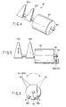
- FIG. 4 is an external appearance diagram of the diverter gate device 420. Here, the plate and the plate detection part are omitted.
- FIG. 5 is a front view of the diverter gate device 420, and FIG. 6 is a side view thereof.
- the diverter gate device 420 is provided with a rotary solenoid 422 as the driver.
- a shaft 423 projecting from one side surface of the rotary solenoid 422 is provided with diverter gates 421a, 421b disposed with a predetermined interval, set according to the length in the conveyance direction of the paper to be conveyed.
- the above-mentioned rotary solenoid 422 rotates the diverter gates 421a, 421b by a predetermined angle in the position (A) direction by applying a positive voltage (+) to a coil (not shown) configuring the solenoid, and rotates the diverter gates 421a, 421b by a predetermined angle in the position (B) direction by applying a negative voltage (-).
- the rotary solenoid has the shaft 423 rotated by a predetermined angle by applying a positive voltage (+) or a negative voltage (-) as mentioned above, however, the shaft 423 is not moved in the front and rear direction in the shaft direction.
- a plate 424 is supported rotatably by the shaft 423 projecting from the other side surface of the rotary solenoid 422 so as to be moved according to the rotation of the shaft 423.
- the plate 424 is provided to the opposite side of the diverter gates 421a, 421b with respect to the shaft 423 center.
- a first plate detecting part 425a capable of detecting the plate 424 moving to a position opposite to the position A with respect to the shaft center and a second plate detecting part 425b capable of detecting the plate 424 moving to a position opposite to the position B with respect to the shaft center are provided on the above-mentioned other side surface as the plate detecting part 40 for detecting the plate 424 to move as mentioned above.
- the first plate detecting part 425a and the second plate detecting part 425b can be composed of an optical sensor comprising for example a pair of a light projector and a light receiver.
- the plate 424 can be disposed so as to pass between the light projector and the light receiver of the first plate detecting part 425a, and between the light projector and the light receiver of the second plate detecting part 425b.
- the plate 424 may be made of a non transmissible material so as to be detected by the first plate detecting part 425a and the second plate detecting part 425b.
- the first plate detecting part 425a and the second plate detecting part 425b may not necessarily be an optical detection sensor.
- a magnetic sensor for detecting the magnetic substance can be used.
- the diverter gates 421a, 421b in the initial position are in a state present at the position A with a positive voltage applied to the coil.
- the plate 424 in the initial state can be detected by the first plate detecting part 425a.
- the rotary solenoid can move the diverter gates 421a, 421b to the position A and move the plate 424 to the position A' and maintain the state even if the voltage supply is stopped.
- the diverter gates 421a, 421b are moved to the position B shown by the broken line so as to be maintained in the state even if the voltage supply is stopped.
- the plate 424 shown by the broken line can be detected by the plate detecting part 425b.
- FIG. 7A shows the voltage waveform to be applied to the rotary solenoid.
- FIG. 7B shows the operation state of the plate 424 moving between the positions A'-B' according to the voltage applied to the rotary solenoid.
- FIG. 7C shows the state of the plate detecting parts 425a, 425b.
- the plate 424 When a positive voltage (+) is applied to the rotary solenoid 420 (timing t1), the plate 424 is moved from the position B' to the position A'. At this time, the plate 424 is detected at timing t2 with the end part thereof passing by the plate detecting part 425a so that an on (ON, detection state) signal is outputted from the plate detecting part 425a. The plate 424 is further moved so as to reach the position A' shown by the solid line at timing t3. Although the solenoid voltage is turned off (OFF) at timing t4, the position A' of the plate 424 is maintained.
- the plate 424 When a negative voltage (-) is applied to the rotary solenoid 420 (timing t5), the plate 424 is moved from the position A' to the position B'. At this time, the plate 424 is detected at timing t6 with the end part thereof passing by the plate detecting part 425b so that an on signal is outputted from the plate detecting part 425b. The plate 424 is further moved so as to reach the position B' shown by the broken line at timing t7. Although the solenoid voltage is turned off at timing t8, the position B' of the plate 424 is maintained.
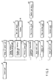
- FIG. 8 is a flow chart showing an example of a malfunction diagnosis method for a diverter gate in a paper processing apparatus of the present invention.
- the mode of the apparatus 100 is changed to the maintenance mode (step S1).
- step S2 a positive voltage (+) is applied to the rotary solenoid (step S2).
- step S4 Whether or not the first plate detecting part 425a outputs "ON” is judged (step S4).
- step S5 In the case where the first plate detecting part 425a outputs "ON”, whether or not the second plate detecting part 425b is "OFF” is judged (step S5).
- step S6 it is judged to be abnormal by the judging part 39.
- step S8 whether or not the second plate detecting part 425b outputs "ON” is judged.
- step S9 In the case where the second plate detecting part 425b outputs "ON”, whether or not the first plate detecting part 425a is "OFF” is judged (step S9).
- step S6 it is judged to be abnormal.
- both the first plate detecting part 425a and the second plate detecting part 425b are in the "OFF" state, or in the case where the "ON"/"OFF" of the first plate detecting part 425a and the second plate detecting part 425b is not changed when the voltage applied to the rotary solenoid is changed for example from a positive voltage (+) to a negative voltage (-), it is considered to be the operation abnormality of the diverter gates 421a, 421b, or the abnormality of the first plate detecting part 425a and the second plate detecting part 425b so as to be judged as the malfunction by the judging part 39.
- both the first plate detecting part 425a and the second plate detecting part 425b are in the "ON" state, it is considered to be the abnormality of the plate detecting part so as to be judged as the malfunction by the judging part 39.
- an ON signal can always be outputted.
- malfunction of the diverter gate can be diagnosed easily in a short time by providing a sensor for detecting the diverter gate at the diverter gate initial position and a position after the operation and judging the sensor output at the time of operating the diverter gate.
Landscapes
- Engineering & Computer Science (AREA)
- Mechanical Engineering (AREA)
- Separation, Sorting, Adjustment, Or Bending Of Sheets To Be Conveyed (AREA)
- Special Conveying (AREA)
Abstract
The present invention provides a paper processing apparatus (100) including a gate device having a driver for rotating a gate (421a) to a conveyance position according to classifying information of paper, a plate (424) supported by a shaft (423) to be rotated synchronously with the rotation of the gate (421a) and a plate (424) detecting part for detecting the plate (424), and a judging part for judging the operation of the gate (421a) based on the detection result of the plate detecting part (425a).
Description
- The present invention relates to a paper processing apparatus for classifying paper provided with classifying information into accumulation boxes based on the classifying information.
- Conventionally, a paper processing apparatus for processing paper, such as a mail automatic reading and sorting machine and a mail aligning and stamping machine comprises about 400 pieces at most of accumulation boxes (hereinafter it will be referred to as a stacker) or accumulation bases. These stackers and accumulation bases are provided with a diverter gate for sorting the paper. Since the diverter gate is an expendable part, malfunction is increased according to the increase of the number of driving. Therefore, an operation confirming work is indispensable for the stable operation of the apparatus.
- For the operation confirming work, first, an operator sets the apparatus into the maintenance mode. Next, while driving the diverter gate, the operator judges the malfunction by the visual observation and the operation noise.
- For simplifying this operation confirming fork, for example,
Jpn. Pat. Appln. KOKAI Publication No. 8-91690 - However, according to the method, correct operations of the diverter gates of an enormous number cannot be confirmed in a short time.
- The present invention has been achieved for solving the above-mentioned problems, and an object thereof is to provide a paper processing apparatus capable of confirming the malfunction of a gate easily in a short time.
- A paper processing apparatus of the present invention comprises: a rotatable gate which is disposed in a conveyance path for conveying paper, and which converts the conveyance direction of the paper according to classifying information of the paper and sorts the paper, a shaft which rotatably supports the gate, a driver which rotates the gate to the conveyance position according to the classifying information of the paper by rotating the shaft, a plate supported by the shaft so as to be rotated synchronously with the rotation of the gate, a plate detecting part which detects the plate, and a judging part which judges the operation of the gate based on the detection results of the plate detecting part.
- This summary of the invention does not necessarily describe all necessary features so that the invention may also be a sub-combination of these described features.
- The invention can be more fully understood from the following detailed description when taken in conjunction with the accompanying drawings, in which:
- FIG. 1 is an external appearance diagram showing an example of a paper processing apparatus of the present invention;
- FIG. 2 is an external appearance diagram showing an example of a paper processing apparatus of the present invention;
- FIG. 3 is a block diagram related to a control part of a paper processing apparatus of the present invention;
- FIG. 4 is an external appearance diagram showing a configuration of an example of a diverter gate device;
- FIG. 5 is an external appearance diagram showing a configuration of an example of a diverter gate device;
- FIG. 6 is an external appearance diagram showing a configuration of an example of a diverter gate device;
- FIG. 7 shows an operation timing of a diverter gate; and
- FIG. 8 is a flow chart showing an example of a malfunction diagnosis method for a diverter gate in a paper processing apparatus of the present invention.
- Hereinafter, embodiments of the present invention will be explained with reference to the drawings.
- FIGS. 1 and 2 are external appearance diagrams showing an example of a paper processing apparatus of the present invention.
- FIG. 1 is a plan view and FIG. 2 is a front view of FIG. 1.
- A
paper processing apparatus 100 comprises a paper supplying and recognizingpart 10 for reading and recognizing a conveyance path for conveying paper; and delivery classifying information mentioned on the paper. Furthermore, it comprises astacker accumulation part 110 for classifying the paper based on the delivery classifying information recognized by the paper supplying and recognizingpart 10. - As to the paper not recognized by the above-mentioned paper supplying and recognizing
part 10, the image information showing the delivery classifying information can be sent to a video coding system (hereinafter it is referred to as the VCS). If an operator inputs the delivery classifying information of the paper based on the image information, a bar code can be printed on the paper by an ink jet printer (hereinafter it is referred to as the IJP) based on the delivery classifying information during the online process. Thereafter, the paper not recognized can be accumulated on the above-mentionedstacker accumulation part 110 based on the bar code information. - The paper supplying and recognizing
part 10 comprises a supplyingpart 1 for collectively supplying the paper to be processed, a taking out part 2 for taking out pieces of the paper one by one for sending the same to the conveyance path, a mechanism detecting part 3a, an excludingaccumulation part 3b, a pre barcode reading part 4, acharacter recognizing part 5,delay conveyance paths IJP printing part 7, a verify barcode reading part 8, astem part 9, and an operatepanel 20. - In the
apparatus 100, when the apparatus is driven by turning on a starting switch of the operate panel 20 (not shown) with the paper set on thesupply part 1, the pieces of paper are taken out from the taking out part 2 one by one. - The mechanism detecting part 3a can detect paper with a foreign substance introduced such as coins, keys, caps of bottles, and seals, and paper out of a standard size out of the taken out paper and exclude the same to the excluding
accumulation part 3b. The paper not excluded and to be supplied can be conveyed to the pre barcode reading part 4 and thecharacter recognizing part 5. - The pre bar
code reading part 4 and thecharacter recognizing part 5 read and recognize the delivery classifying information such as the bar code, the postal code and the address, written on the paper. - The
delay conveyance path 6a is a conveyance part for ensuring the time for the recognition in thecharacter recognizing part 5. Moreover, thedelay conveyance path 6b is also a conveyance part for producing the processing time of the VCS process of the paper not read out in thecharacter recognizing part 5. According to the VCS process, an image of the paper is displayed on a monitor while conveying the paper in thedelay conveyance path 6b so that an operator can input the delivery classifying information. - The IJP
printing part 7 can convert the delivery classifying information set based on the pre barcode reading part 4, thecharacter recognizing part 5 or the VCS keyboard information into a bar code of a special format. Moreover, the printed content can be rechecked by the verify barcode reading part 8. - Thereafter, the control part determines the destination stacker and operates a gate (not shown) of the
stem part 9 for accumulating the paper to the stacker based on the determination result of this destination stacker, for sorting to each stage. The sorted paper is conveyed to thestacker accumulation part 110 so as to be guided by the operation of the diverter gate provided at the inlet of the stacker according to the decided destination stacker and accumulated in the stacker. - FIG. 3 is a block diagram related to the above-mentioned control part.
- A
control part 30 controls a taking outcontrol part 31 for controlling the periphery of the supply and taking out part, a foreign substancedetection control part 32 for excluding the paper with a foreign substance introduced, a reading partinterface control part 33 for trading the delivery classifying information of the paper, aprinting control part 34 for bar code printing of the information by the IJP, a conveying and classifyingcontrol part 35 for conveying and accumulating the paper in a decided stacker, amode control part 41 for switching the operation mode of the apparatus such as the drive mode and the maintenance mode, ajudging part 39 for judging the malfunction of the periphery of the diverter gate at the time of the maintenance mode, and apanel control part 36 for displaying the paper accumulation information and the apparatus abnormality information on the operate panel. - The reading part
interface control part 33 sends the paper read out data in thebar code reader 37 and the paper read out data in thescanner 38 each to thecontrol part 30. Here, according to the data judgment and decision on the conveyance and classification of the paper, the decision results are sent to the conveying and classifyingcontrol part 35 as the conveyance-classification information. - The conveying and classifying
control part 35 operates various kinds of gates such as the gate of the above-mentionedstem part 9 and adiverter gate device 420 using agate driving circuit 42 based on the conveyance-classification information. - The judging
part 39 judges the malfunction in the periphery of the diverter gate device according to the detection signal from theplate detection part 40 mounted to the diverter gate device. Thecontrol part 30 controls thepanel control part 36 based on the judgment result so as to display the malfunction in the periphery of the diverter gate device on the operatepanel 20. - The configuration and the operation of an example of the diverter gate device used in the present invention will be explained with reference to FIGS. 4 to 6.
- FIG. 4 is an external appearance diagram of the
diverter gate device 420. Here, the plate and the plate detection part are omitted. FIG. 5 is a front view of thediverter gate device 420, and FIG. 6 is a side view thereof. - The
diverter gate device 420 is provided with arotary solenoid 422 as the driver. Ashaft 423 projecting from one side surface of therotary solenoid 422 is provided withdiverter gates rotary solenoid 422 rotates thediverter gates diverter gates shaft 423 rotated by a predetermined angle by applying a positive voltage (+) or a negative voltage (-) as mentioned above, however, theshaft 423 is not moved in the front and rear direction in the shaft direction. - Furthermore, a
plate 424 is supported rotatably by theshaft 423 projecting from the other side surface of therotary solenoid 422 so as to be moved according to the rotation of theshaft 423. According to thediverter gate device 420, theplate 424 is provided to the opposite side of thediverter gates shaft 423 center. When thediverter gates plate 424 can be moved clockwise from the position on the opposite side of the position B with respect to the shaft center to the position on the opposite side of the position A with respect to the shaft center. - Moreover, a first
plate detecting part 425a capable of detecting theplate 424 moving to a position opposite to the position A with respect to the shaft center and a secondplate detecting part 425b capable of detecting theplate 424 moving to a position opposite to the position B with respect to the shaft center are provided on the above-mentioned other side surface as theplate detecting part 40 for detecting theplate 424 to move as mentioned above. - The first
plate detecting part 425a and the secondplate detecting part 425b can be composed of an optical sensor comprising for example a pair of a light projector and a light receiver. For example, as shown in FIG. 5, theplate 424 can be disposed so as to pass between the light projector and the light receiver of the firstplate detecting part 425a, and between the light projector and the light receiver of the secondplate detecting part 425b. - Moreover, the
plate 424 may be made of a non transmissible material so as to be detected by the firstplate detecting part 425a and the secondplate detecting part 425b. The firstplate detecting part 425a and the secondplate detecting part 425b may not necessarily be an optical detection sensor. For example, with a part of the plate made of a magnetic substance, a magnetic sensor for detecting the magnetic substance can be used. - Next, with reference to FIG. 6, the operation of the above-mentioned
diverter gate device 420 will be explained. Thediverter gates - In the explanation below, the expression of "applying a voltage to the coil" will be substituted by the expression of "applying a voltage to the rotary solenoid".
- The
plate 424 in the initial state can be detected by the firstplate detecting part 425a. When a positive voltage of a predetermined pulse width is applied, the rotary solenoid can move thediverter gates plate 424 to the position A' and maintain the state even if the voltage supply is stopped. - Next, when the
shaft 423 is rotated by the application of a negative voltage to therotary solenoid 422, thediverter gates plate 424 shown by the broken line can be detected by theplate detecting part 425b. - Accordingly, the switching operation of the
diverter gates - Next, with reference to FIG. 7, the operation timing of the diverter gate will be explained.
- FIG. 7A shows the voltage waveform to be applied to the rotary solenoid. FIG. 7B shows the operation state of the
plate 424 moving between the positions A'-B' according to the voltage applied to the rotary solenoid. FIG. 7C shows the state of theplate detecting parts - When a positive voltage (+) is applied to the rotary solenoid 420 (timing t1), the
plate 424 is moved from the position B' to the position A'. At this time, theplate 424 is detected at timing t2 with the end part thereof passing by theplate detecting part 425a so that an on (ON, detection state) signal is outputted from theplate detecting part 425a. Theplate 424 is further moved so as to reach the position A' shown by the solid line at timing t3. Although the solenoid voltage is turned off (OFF) at timing t4, the position A' of theplate 424 is maintained. - When a negative voltage (-) is applied to the rotary solenoid 420 (timing t5), the
plate 424 is moved from the position A' to the position B'. At this time, theplate 424 is detected at timing t6 with the end part thereof passing by theplate detecting part 425b so that an on signal is outputted from theplate detecting part 425b. Theplate 424 is further moved so as to reach the position B' shown by the broken line at timing t7. Although the solenoid voltage is turned off at timing t8, the position B' of theplate 424 is maintained. - Since the operation of moving the
plate 424 between the positions A'-B' is the same for timing t9 and thereafter, explanation is omitted. Accordingly, by repeatedly applying the solenoid voltage for moving theplate 424 and furthermore, monitoring the "ON"/"OFF" state of theplate detecting parts diverter gates - FIG. 8 is a flow chart showing an example of a malfunction diagnosis method for a diverter gate in a paper processing apparatus of the present invention.
- First, the mode of the
apparatus 100 is changed to the maintenance mode (step S1). - Next, a positive voltage (+) is applied to the rotary solenoid (step S2).
- Whether or not the first
plate detecting part 425a outputs "ON" is judged (step S4). - In the case where the first
plate detecting part 425a outputs "ON", whether or not the secondplate detecting part 425b is "OFF" is judged (step S5). - On the other hand, in the case where the first
plate detecting part 425a is in the "OFF" state, it is judged to be abnormal by the judging part 39 (step S6). - In the case where the second
plate detecting part 425b is "OFF", subsequently, a negative voltage (-) is applied to the rotary solenoid (step S7). - Thereafter, whether or not the second
plate detecting part 425b outputs "ON" is judged (step S8). - In the case where the second
plate detecting part 425b outputs "ON", whether or not the firstplate detecting part 425a is "OFF" is judged (step S9). - On the other hand, in the case where the second
plate detecting part 425b is in the "OFF" state, it is judged to be abnormal (step S6). - In the case where the first
plate detecting part 425a is "OFF", it is judged to be normal. - In the case where both the first
plate detecting part 425a and the secondplate detecting part 425b are in the "OFF" state, or in the case where the "ON"/"OFF" of the firstplate detecting part 425a and the secondplate detecting part 425b is not changed when the voltage applied to the rotary solenoid is changed for example from a positive voltage (+) to a negative voltage (-), it is considered to be the operation abnormality of thediverter gates plate detecting part 425a and the secondplate detecting part 425b so as to be judged as the malfunction by the judgingpart 39. - Or in the case where both the first
plate detecting part 425a and the secondplate detecting part 425b are in the "ON" state, it is considered to be the abnormality of the plate detecting part so as to be judged as the malfunction by the judgingpart 39. For example, in the case where garbage, dusts, or the like are stagnated on at least one of the firstplate detecting part 425a and the secondplate detecting part 425b so as to block between the light projector and the light receiver, an ON signal can always be outputted. - In the real diverter gate analysis, by carrying out the "ON"/"OFF" operation of the diverter gate for a plurality of times successively for a plurality of diverter gates, the operation comparison confirmation can be carried out.
- Accordingly, by use of the present invention, malfunction of the diverter gate can be diagnosed easily in a short time by providing a sensor for detecting the diverter gate at the diverter gate initial position and a position after the operation and judging the sensor output at the time of operating the diverter gate.
- It is explicitly stated that all features disclosed in the description and/or the claims are intended to be disclosed separately and independently from each other for the purpose of original disclosure as well as for the purpose of restricting the claimed invention independent of the composition of the features in the embodiments and/or the claims. It is explicitly stated that all value ranges or indications of groups of entities disclose every possible intermediate value or intermediate entity for the purpose of original disclosure as well as for the purpose of restricting the claimed invention, in particular as limits of value ranges.
Claims (6)
- A paper processing apparatus (100)
characterized by comprising:a rotatable gate (421a) which is disposed in a conveyance path for conveying paper, and which converts the conveyance direction of the paper according to classifying information of the paper and sorts the paper,a shaft (423) which rotatably supports the gate (421a, 421b),a driver (422) which rotates the gate to the conveyance position according to the classifying information of the paper by rotating the shaft (423),a plate (424) supported by the shaft (423) so as to be rotated synchronously with the rotation of the gate (421a, 421b),a plate detecting part (425a) which detects the plate (424), anda judging part (39) which judges the operation of the gate based on the detection results of the plate detecting part (425a). - The paper processing apparatus according to claim 1, characterized in that the gate (421a, 421b) is a diverter gate.
- The paper processing apparatus according to claim 1 or 2, characterized in that the driver (422) is composed of a rotary solenoid which rotates the shaft (423) in one direction by application of a positive voltage, rotates the shaft (423) in a direction opposite to the direction by application of a negative voltage, and does not move the shaft (423) in the front and rear direction in the shaft direction by application of a positive voltage or a negative voltage.
- The paper processing apparatus according to anyone of the preceding claims, characterized in that the driver (422) is composed of the rotary solenoid, which rotates the shaft (423) in one direction to an angle until the gate (421a) reaches a first conveyance position and maintains the state by application of a positive voltage of a predetermined pulse width, rotates the shaft (423) in a direction opposite to the direction to an angle until the gate reaches a second conveyance position and maintains the state by application of a negative voltage of a predetermined pulse width, and does not move the shaft (423) in the front and rear direction by application of a positive voltage or a negative voltage.
- The paper processing apparatus according to anyone of the preceding claims, characterized in that the plate detecting part (425a) comprises a first plate detecting part capable of detecting the rotation of the plate (422) when a positive voltage is applied, and a second plate detecting part capable of detecting the rotation of the plate (422) when a negative voltage is applied.
- The paper processing apparatus according to claim 5, characterized in that the judging part (39) makes judgment based on both of the detection result of the first plate detecting part (425a) and the detection result of the second plate detecting part (425b).
Applications Claiming Priority (1)
| Application Number | Priority Date | Filing Date | Title |
|---|---|---|---|
| JP2005190678A JP2007008645A (en) | 2005-06-29 | 2005-06-29 | Self-diagnosis device for divertor gate in paper sheet processing equipment |
Publications (1)
| Publication Number | Publication Date |
|---|---|
| EP1739043A2 true EP1739043A2 (en) | 2007-01-03 |
Family
ID=37037088
Family Applications (1)
| Application Number | Title | Priority Date | Filing Date |
|---|---|---|---|
| EP06005073A Withdrawn EP1739043A2 (en) | 2005-06-29 | 2006-03-13 | Paper processing apparatus |
Country Status (4)
| Country | Link |
|---|---|
| US (1) | US20070005184A1 (en) |
| EP (1) | EP1739043A2 (en) |
| JP (1) | JP2007008645A (en) |
| CA (1) | CA2539247A1 (en) |
Families Citing this family (3)
| Publication number | Priority date | Publication date | Assignee | Title |
|---|---|---|---|---|
| CN103318685B (en) * | 2013-07-05 | 2016-01-20 | 广州广电运通金融电子股份有限公司 | A kind of Sheet medium transmission passage reversing arrangement |
| DE102017201758B4 (en) * | 2017-02-03 | 2025-04-17 | Magna powertrain gmbh & co kg | Method for measuring an anchor position and coupling device using the method |
| WO2018190238A1 (en) * | 2017-04-11 | 2018-10-18 | アンリツインフィビス株式会社 | Article distribution device |
Citations (1)
| Publication number | Priority date | Publication date | Assignee | Title |
|---|---|---|---|---|
| JPH0891690A (en) | 1994-09-21 | 1996-04-09 | Toshiba Corp | Paper processing equipment |
Family Cites Families (13)
| Publication number | Priority date | Publication date | Assignee | Title |
|---|---|---|---|---|
| US3870868A (en) * | 1972-07-21 | 1975-03-11 | Pennsylvania Res Ass Inc | Control mechanisms for document-handling apparatus |
| US4202542A (en) * | 1977-12-01 | 1980-05-13 | International Business Machines Corporation | Apparatus for handling flexible sheet material of different sizes |
| US4579326A (en) * | 1984-12-06 | 1986-04-01 | Xerox Corporation | Compact document handling system |
| JPS61276089A (en) * | 1985-05-31 | 1986-12-06 | 株式会社東芝 | Paper money transport controller |
| JPH02189073A (en) * | 1989-01-17 | 1990-07-25 | Fuji Xerox Co Ltd | Picture data adjustment system for picture reader |
| US5076560A (en) * | 1990-11-23 | 1991-12-31 | Eastman Kodak Company | Recirculating document feeder and method |
| US5515152A (en) * | 1994-10-03 | 1996-05-07 | Xerox Corporation | Multi-gate tandem decurler |
| US6244583B1 (en) * | 1997-03-11 | 2001-06-12 | Minolta Co., Ltd. | Stack transport for a sorter with pressing device |
| US6155775A (en) * | 1998-06-09 | 2000-12-05 | R. R. Donnelley & Sons Company | Destacking feeder |
| US6412769B1 (en) * | 1999-06-28 | 2002-07-02 | Kyocera Mita Corporation | Paper feeder |
| US6381442B1 (en) * | 2000-01-31 | 2002-04-30 | Sharp Kabushiki Kaisa | Image forming apparatus with paper post-treatment device |
| EP1785954B1 (en) * | 2000-03-23 | 2016-11-30 | Kabushiki Kaisha Toshiba | Reversing and aligning mechanism for sheet processing apparatus |
| CN1254423C (en) * | 2000-08-21 | 2006-05-03 | 佳能株式会社 | Paper transport device and image reading device |
-
2005
- 2005-06-29 JP JP2005190678A patent/JP2007008645A/en active Pending
-
2006
- 2006-03-10 CA CA002539247A patent/CA2539247A1/en not_active Abandoned
- 2006-03-13 EP EP06005073A patent/EP1739043A2/en not_active Withdrawn
- 2006-03-21 US US11/384,265 patent/US20070005184A1/en not_active Abandoned
Patent Citations (1)
| Publication number | Priority date | Publication date | Assignee | Title |
|---|---|---|---|---|
| JPH0891690A (en) | 1994-09-21 | 1996-04-09 | Toshiba Corp | Paper processing equipment |
Also Published As
| Publication number | Publication date |
|---|---|
| JP2007008645A (en) | 2007-01-18 |
| CA2539247A1 (en) | 2006-12-29 |
| US20070005184A1 (en) | 2007-01-04 |
Similar Documents
| Publication | Publication Date | Title |
|---|---|---|
| US7837109B2 (en) | Processing method and apparatus for recording media having printed magnetic ink characters | |
| US7777919B2 (en) | Modular document sorting apparatus and method | |
| DE69325339T2 (en) | Method and device for distinguishing items such as envelopes | |
| JP2001517140A (en) | Postal code evaluation system | |
| US20070139703A1 (en) | Print inspecting apparatus | |
| US20070005184A1 (en) | Paper processing apparatus | |
| US8485520B2 (en) | Sheet stacking apparatus with skew value sensor for sheet stack designation | |
| EP1443454B1 (en) | Magnetic detection device | |
| JP4454759B2 (en) | Paper sheet overlap judgment method and paper sheet sorting apparatus | |
| US20050108163A1 (en) | Method and system for processing checks | |
| JP5911736B2 (en) | Paper sheet take-out device and paper sheet processing device | |
| JP4653412B2 (en) | Bar code recognition processing device | |
| US7801701B2 (en) | Inserter integrated method and system for logic analyzing error conditions | |
| US8374398B2 (en) | Linear image lift array for transported material | |
| KR20020046419A (en) | apparatus for managing a check and method for managing thereof | |
| JP2013066825A (en) | Paper sheet processor and control method of paper sheet processor | |
| WO2006011746A1 (en) | Mail processing system having automatic mail classifying device | |
| JPS61275986A (en) | Front surface and rear surface deciding device for paper | |
| JP5989880B2 (en) | Paper sheet take-out device and paper sheet processing device | |
| JP6276346B2 (en) | Paper sheet take-out device and paper sheet processing device | |
| JP2000262984A (en) | Mail processing apparatus and mail processing method | |
| JP3551836B2 (en) | Film discharge direction determination method | |
| JPH0486970A (en) | Classifying selector for printed matters with lottery | |
| JPH0375821A (en) | Printing device | |
| JPH054752A (en) | Paper sheets processor |
Legal Events
| Date | Code | Title | Description |
|---|---|---|---|
| PUAI | Public reference made under article 153(3) epc to a published international application that has entered the european phase |
Free format text: ORIGINAL CODE: 0009012 |
|
| 17P | Request for examination filed |
Effective date: 20060313 |
|
| AK | Designated contracting states |
Kind code of ref document: A2 Designated state(s): AT BE BG CH CY CZ DE DK EE ES FI FR GB GR HU IE IS IT LI LT LU LV MC NL PL PT RO SE SI SK TR |
|
| AX | Request for extension of the european patent |
Extension state: AL BA HR MK YU |
|
| STAA | Information on the status of an ep patent application or granted ep patent |
Free format text: STATUS: THE APPLICATION HAS BEEN WITHDRAWN |
|
| 18W | Application withdrawn |
Effective date: 20070427 |