EP1739037A2 - Paper sheet supply apparatus - Google Patents
Paper sheet supply apparatus Download PDFInfo
- Publication number
- EP1739037A2 EP1739037A2 EP06004625A EP06004625A EP1739037A2 EP 1739037 A2 EP1739037 A2 EP 1739037A2 EP 06004625 A EP06004625 A EP 06004625A EP 06004625 A EP06004625 A EP 06004625A EP 1739037 A2 EP1739037 A2 EP 1739037A2
- Authority
- EP
- European Patent Office
- Prior art keywords
- paper sheet
- input unit
- paper
- support plate
- stacking
- Prior art date
- Legal status (The legal status is an assumption and is not a legal conclusion. Google has not performed a legal analysis and makes no representation as to the accuracy of the status listed.)
- Withdrawn
Links
Images



Classifications
-
- B—PERFORMING OPERATIONS; TRANSPORTING
- B65—CONVEYING; PACKING; STORING; HANDLING THIN OR FILAMENTARY MATERIAL
- B65H—HANDLING THIN OR FILAMENTARY MATERIAL, e.g. SHEETS, WEBS, CABLES
- B65H1/00—Supports or magazines for piles from which articles are to be separated
- B65H1/02—Supports or magazines for piles from which articles are to be separated adapted to support articles on edge
-
- B—PERFORMING OPERATIONS; TRANSPORTING
- B65—CONVEYING; PACKING; STORING; HANDLING THIN OR FILAMENTARY MATERIAL
- B65H—HANDLING THIN OR FILAMENTARY MATERIAL, e.g. SHEETS, WEBS, CABLES
- B65H1/00—Supports or magazines for piles from which articles are to be separated
- B65H1/30—Supports or magazines for piles from which articles are to be separated with means for replenishing the pile during continuous separation of articles therefrom
-
- B—PERFORMING OPERATIONS; TRANSPORTING
- B65—CONVEYING; PACKING; STORING; HANDLING THIN OR FILAMENTARY MATERIAL
- B65H—HANDLING THIN OR FILAMENTARY MATERIAL, e.g. SHEETS, WEBS, CABLES
- B65H2701/00—Handled material; Storage means
- B65H2701/10—Handled articles or webs
- B65H2701/19—Specific article or web
- B65H2701/1912—Banknotes, bills and cheques or the like
Definitions
- the present invention relates to a paper sheet supply apparatus, which is incorporated in a paper sheet processing apparatus to process paper sheets such as paper money, and supplies paper sheets inputted in a stacked state.
- a conventional paper sheet supply apparatus has a supply table which inputs paper sheets by stacking in a stand-up state, and a backup plate which supports the rear end of the stacking direction of the paper sheets inputted in a stand-up state on the supply table and presses the paper sheets to a pickup roller provided at the front end of the stacking direction.
- the operator moves the backup plate in the direction of separating away from the pickup roller against the pressing force of the backup plate, and inserts paper sheets into a space made between the pickup roller and backup plate.
- the operator must move the backup plate in the direction of separating away from the paper sheets already input to the supply table by holding the already input paper sheets, and insert the next paper sheets into a space made between the backup plate and the already input paper sheets. This deteriorates ease of operation by the operator.
- a paper sheet supply apparatus comprising a first input unit which inputs a first paper sheet by stacking in a stand-up state; a backup plate which presses a paper sheet placed at the other end of the direction of stacking the first paper sheet input to the first input unit in a first direction toward a pickup roller provided at one end of the first input unit, so as to press a paper sheet placed at one end of the stacking direction to the pickup roller; a second input unit which is connected continuously to the other end of the fist input unit and inputs a second paper sheet by stacking in a stand-up state; a support plate which is placed between the backup plate and second paper sheet, supports a paper sheet placed at one end of the direction of stacking the second paper sheet input to the second input unit, and presses the second paper sheet in a second direction reverse to the first direction along the stacking direction; and an evacuation mechanism which evacuates the backup plate and support plate from between the first paper sheet and second paper sheet, after
- a paper sheet processing apparatus comprising a paper sheet supply unit which supplies paper sheets input by stacking in a stand-up state to a take-out position sequentially from a paper sheet placed at one end of the stacking direction; a pickup roller which rotates while contacting the paper sheet supplied to the take-out position, and takes out the paper sheet onto a feeding path; an inspection unit which inspects the paper sheet taken out and fed on the feeding path; and a processor which processes the paper sheet according to the result of inspection in the inspector, wherein the paper supply unit has a first input unit which inputs a first paper sheet by stacking in a stand-up state; a backup plate which presses a paper sheet placed at the other end of the direction of stacking the first paper sheet input to the first input unit in a first direction toward a pickup roller provided at one end of the first input unit, so as to press a paper sheet placed at one end of the stacking direction to the pickup roller; a second input unit which is connected continuously to the other end of the fi
- FIG. 1 schematically shows the configuration of a paper money sorting system 100 (hereinafter called simply a system) as a paper sheet processing apparatus according to an embodiment of the invention.
- the system 100 has a paper money sorting machine 101, and a control unit 102 for operating and controlling the paper money sorting machine 101.
- the control unit 102 consists of a personal computer, for example, and has an operation input unit 103 such as a keyboard and mouse, a display unit 104, a control unit 105, and a hard disc unit 106 for recording.
- an operation input unit 103 such as a keyboard and mouse
- a display unit 104 such as a liquid crystal display
- a control unit 105 such as a liquid crystal display
- a hard disc unit 106 for recording.
- the paper sorting machine 101 has a housing 1.
- a table unit 1A is provided at the center of one side of the housing 1.
- the table unit 1A is provided with a paper money supply unit 2 (paper sheet supply unit) for inputting paper sheets P in a stacked state.
- the paper money P is stacked in a stand-up state in the paper supply unit 2.
- the paper money P is pressed to a pickup roller 5 by a backup plate 4 energized by a spring 3.
- the paper money P placed at one end of the stacking direction is taken out downward in the drawing by the rotation of the pickup roller 5.
- the paper money supply unit 2 will be explained in detail later.
- a separating unit 32 and a feeding unit 37 are provided under the pickup roller 5.
- the paper money P fed through the feeding unit 37 described later is fed by a clamp-type feeding unit 7 consisting of a belt 6a and a roller 6b.
- the feeding unit 7 is provided with a position correcting unit 8 which automatically corrects a shift and skew of the taken-out paper money P.
- An inspection unit 9 is provided in the downstream side of the paper money feeding direction of the feeding unit 7.
- the inspection unit 9 reads various information from the surface of the paper money P fed by a pair of rollers 10 by not-shown optical sensors, and logically operates and compares the information with reference information, thereby checking double take-in, stain, damage, amount of money, and 4 directions of top/bottom and front/back.
- a first branching unit 11 is provided in the downstream side of the paper money feeding direction of the inspection unit 9.
- the first branching unit 11 leads a paper money judged not a normal paper money P in the inspection unit 9, such as a paper money doubly taken in or skewed largely over a preset level, to a rejection box 12, and a paper money judged a normal paper money P to a second branching unit 13.
- the second branching unit 13 branches the paper money P feeding direction into first and second directions.
- a left/right reversing path 14 is provided in the first direction.
- the left/right reversing path 14 has a twisting belt 15 to reverse the paper money P 180° to the left and right.
- a simple belt conveyer 16 is provided in the second direction, to convey the paper money P in as it is.
- the paper money branched and fed in the first and second directions are joined in a joining unit 17.
- the lengths of the routes to the joining part 17 are made equal, so that an interval is not shifted after the paper money is joined.
- a third branching unit 18 is provided in the downstream side of the paper money feeding direction of the joining unit 17.
- the third branching unit 18 branches the paper money P feeding direction into third and fourth directions.
- a switchback unit 19 is provided in the third direction.
- the switchback unit 19 is provided with a reversing box 20, and a tapping wheel 21 which presses the rear end of the paper money P led to the reversing box 20 to the reversing roller 21a.
- the paper money P is fed out from the reversing box 20 with the top and bottom reversed.
- a simple belt conveyer 22 is provided in the fourth direction, and the paper money P is fed while keeping the position.
- the paper money branched and fed in third and fourth directions is joined in the joining unit 23.
- the lengths of the routes of the branching path to the joining unit 23 are set equal, so that an interval is not shifted after the paper money is joined.
- a horizontal feeding path 24 is provided in the downstream side of the paper money feeding direction of the joining part 23.
- the horizontal feeding path 24 is provided with fourth to seventh branching units 25a - 25d, which is one less than the number of the parts to be divided.
- first to fourth stacker units 26a - 26d are provided as stacking units for different kinds of paper money.
- the paper money P is horizontally stacked in the stacker units 26a - 26d.
- a 100-sheet sealing unit 27 is provided under the fourth branching unit 25a.
- the 100-sheet sealing unit 27 has a stacker 28 to classify the paper money P by stacking 100 sheets, a feeder 28a to feed the paper sheet P from the stacker 28, and a belt binder 29 to bind the paper P fed from the feeder 28 with a paper belt 29a.
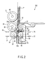
- FIG. 2 schematically shows the structure of a take-out unit 200, which separates one by one the paper money P input through the paper money supply unit 2, and takes it out onto the feeding path.
- the take-out unit 200 has a separator 32 and a feeder 37, in addition to the pickup roller 5.
- Each roller (not shown) explained below shall have two rollers along its axis of rotation.
- the separator 32 has feeding rollers 30. These feeding rollers 30 are pressed by separating rollers 31. The feeding rollers 30 are provided contacting the surface of the paper money P that is rollingly contacted by the pickup roller 5.
- the feeder 37 is located under the feeding rollers 30, and provided with driving rollers 34.
- the driving rollers 34 are rollingly contacted by pinch rollers 35.
- the paper money P passing through a separating nip 33a between the feeding rollers 30 and separating rollers 31 is clamped and pulled out by a feeding nip 33b between the driving rollers 34 and pinch rollers 35, and fed to a processor in a later stage.
- the pickup roller 5, feeding roller 30, separating roller 31, driving roller 34 and pinch roller 35 are provided one each on the left and right along the direction of the longish side of paper money, and function to take out the paper money P along the direction of the shorter side.
- the peripheral surface of the feeding roller 30 is made of rubber, and fixed to a shaft 36 through a one-way clutch.
- the feeding roller 30 is freely rotatably in the paper money P take-out direction, and devised to decrease resistance when the paper money P is pulled out by the driving roller 34 and pinch roller 35.
- the whole periphery of the separating roller 31 is formed by rubber, and a coefficient of friction to the paper money P is higher than that between the paper money P.
- the separating roller 31 is rotatably fixed to the upper end portion of an oscillation lever 59 through a shaft 58.
- the lower end portion of the oscillation lever 59 is rotatably supported by a shaft 60.
- the oscillation lever 59 is energized by a spring 62, and presses the separating roller 31 to the feeding roller 30.
- the separating roller 31 is rotated with the feeding roller 30 in the take-out direction, but the reversing torque is always acted in the reversing direction, generating a separating force to the paper money P.
- the driving roller 34 is rotatably fixed to a frame through a shaft 69.
- the pinch roller 35 is rotatably supported by a shaft 73. Both end portions of the shaft 73 are energized toward the driving roller 34 by a not-shown spring. The pinch roller 35 is pressed to the driving roller 34 by this energizing force, and generates a feeding force.
- a first detector 76 is provided to detect the paper money P fed out from the separating nip 33a between the feeding roller 30 and separating roller 31.
- a second detector 77 is provided to detect the paper money P fed out from the pair of conveying rollers 34 and 35.
- the first and second detectors 76 and 77 are photo-transmissive optical sensors, for example.
- paper money P as a processing object is input in a stacked state through the paper money supply unit 2.
- the input paper money P is energized toward the pickup roller 5 by the backup plate 4, and the paper money P placed at one end of the stacking direction is pressed to the pickup roller 5.
- the pickup roller 5 When the pickup roller 5 is rotated, the paper money P pressed to the roller 5 by the backup plate 4 and placed at one end of the stacking direction is taken out downward. In this time, a second and subsequent paper money may be taken out together with the first taken-out paper money P by the friction between the paper money P. If two or more paper money P are taken out together with the first paper money P, the second and subsequent paper money are separated by a reverse direction torque generated by the separating roller 31, when passing through the separating nip 33a between the feeding roller 30 and separating roller 31.
- the first paper money P is held by the feeding nip 33b between the pair of conveying rollers 34 and 35, pulled out from the separating nip 33a, and fed to a processor in a later stage.
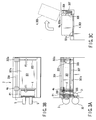
- FIG. 3A shows a front view of a first input unit 301 of the paper money supply unit 2, viewed from the front side of the paper sheet processing apparatus 100.
- FIG. 3B shows a plane view of the first input unit 301, viewed from the top.
- FIG. 3C shows a side view of the first input unit 301, viewed from the upstream side of the paper money P supplying direction.
- the paper money supply unit 2 has a first input unit 301 which inputs paper money P1 by stacking in a stand-up state, and a second input unit 302 which inputs paper money P2 by stacking in a stand-up state.
- the pickup rollers 5 are placed at one end of the first input unit 301 along the paper money P1 stacking direction.
- the second input unit 302 is assumed to haven been externally connected to the other end of the first input unit 301, apart from the pickup rollers 5.
- the paper money P1 and P2 input to the first and second input units 301 and 302 are of not different kind.
- the paper money of a batch to be input first to the paper money supply unit 2 is called P1 (first paper sheet)
- P2 second paper sheet
- the first input unit 301 is also provided with a plate 303 to support the paper money P2 input to the second input unit 302, in addition to the backup plate 4.
- a slid shaft 304 is provided extending in the direction of stacking the paper money P1 and P2 (e.g., in the lateral direction in FIG. 4).
- One end of the backup plate 4 and support plate 303 is rotatably fixed to the slide shaft 304 as shown in FIG. 3C, and slidable along the slide shaft 304 in the direction of stacking the paper money P.
- a slider 4a is used to fix the backup plate 4 rotatably to the slid shaft 304.
- One end of a pressing spring 305 is fixed to the slider 4a, and the other end of the pressing spring 305 is fixed to the housing of the apparatus.
- the midstream part of the pressing spring 305 is laid over a pulley 306. Therefore, the backup plate 4 is always energized by the pressing spring 305 in the direction (first direction) indicated by an arrow F1 in FIG. 3B, and presses the paper money placed at the other end of the stacking direction in the first direction (to the left in the drawing) toward the pickup rollers 5, just like pressing the paper money placed at one end of the direction of stacking the paper money P1 input to the first input unit 301, to the pickup roller 5.
- a slider 303a is used to fix the support plate 303 rotatably to the slide shaft 304.
- One end of a constant-load spring 307 is fixed to the slider 303a, and the other end of the spring 307 is fixed to the housing of the apparatus.
- the midstream of the constant-load spring 307 is laid over a pulley 308.
- the constant-load spring 307 functions to give a constant load at all times regardless of the slide position of the slider 303a.
- the support plate 303 presses the paper money P2 in the direction of an arrow F2 in the drawing (second direction) to prevent the paper money placed at one end of the paper money P2 stacking direction from falling down to the pickup rollers 5.
- the support plate 303 is moved to the pickup rollers 5 together with the paper money P2 by the pressing force F3 by the operator, and placed close to the backup plate 4.
- the above-mentioned slide shaft 304 and sliders 4a and 303a function also as an evacuation mechanism of the present invention. Namely, the backup plate 4 having the slider 4a and the support plate 303 having the slider 303a can be evacuated from the first input unit 301 by rotating these plates upward around the slide shaft 304 as indicated by a broken line in FIG. 3A, and the paper money P1 and P2 can be joined.
- a magnet 310 is provided on the back of the backup plate 4 opposed to the support plate 303, and a magnetic member 311 is provided on the back of the support plate 303 opposed to the backup plate 4.
- the magnet 310 and magnetic member 311 are removably connected by the magnetism when the backup plate 4 and support plate 303 are moved close to each other, and functioned to combine these plates as one body.
- the plates 4 and 303 can be evacuated as one body around the slid shaft 304.
- the magnet 310 and magnetic member 311 may be reversely provided.
- a supply case 312 containing paper money P2 is removably set in the second input unit 302.
- the supply case 312 has a rear wall 313 which supports the paper money placed at the other end apart from the pickup rollers 5 along the paper money P2 stacking direction, and opens one end of the paper money P2 stacking direction to the support plate 303.
- the second input unit 302 is inclined downward in the direction of separating away from the pickup rollers 5. The inclined angle can be optionally changed according to the kinds of paper sheets to be handled.
- the paper money P2 input to the second input unit 302 slides by the own weight on a bottom surface 312a of the case toward the rear wall 313 of the supply case 312, and the paper money placed at the other end of the stacking direction is supported by the rear wall 313. This prevents loosing the position of the paper money P2 in the state that the supply case 312 is set in the second input unit 302.
- the height of the bottom surface 312a of the supply case 312 set in the second input unit 3 is designed a little higher than the bottom surface 301a of the first input unit 301, as shown partially magnified in FIG. 4.
- the paper money P1 is input to the first input unit 301 and taken out by the pickup rollers 5. While the paper money P1 is being taken out, the supply case 312 containing the paper money P and P3 parted by a header card (not shown) is set in the second input unit 302. Only the paper money P is additionally supplied to the first input unit 301.
- the paper money P3 remained in the supply case 312 in the second input unit 302 is energized downward by the own weight along the inclined bottom 312a of the supply case 312, and the rear end of the stacking direction is supported by the rear wall 313 of the case to prevent collapsing of the stack.
- the support plate 303 may be set by a not-shown stopper in proximity to the entrance of the first input unit 301, or may be placed in the second input unit 302 by extending the slide shaft 304 to the second input unit 302.
- the paper money P2 When the paper money P2 is pressed in the direction of the arrow F3 and pushed into the first input unit 301 by the operator, the paper money P2 is held between the support plate 303 and the operator's hand, with the paper money placed at one end supported by the support plate 303, and moved toward the pickup rollers 5 together with the support plate 303. In this time, the operator presses the paper money P2 by the pressing force F3 against the pressing force F2 given by the constant-load spring 307 of the support plate 303.
- the lower end side of the paper money P2 passes through the part connecting the lower surface 312a of the supply case 312 and the lower surface 301a of the first input unit 301.
- the lower surface 312a is placed a little higher than the lower surface 301a, the lower end side of the paper money P2 is not caught by the height difference causing a jam.
- the support plate 303 contacts the backup plate 4 at the end of the movement.
- the magnet 310 fixed to the backup plate 4 is connected to the magnetic member 311 fixed to the support plate 303 by the magnetism, and the two plates 4 and 303 are combined as one body.
- FIG. 7 shows this state. Therefore, the additionally supplied paper P2 is joined with the paper money P1 previously input to the first input unit 301.
- the two plates 4 and 303 evacuated upward are moved in the direction of separating away from the pickup rollers 5 along the slide shaft 304 as indicated by an arrow in FIG. 7, and rotated from the position indicated by a broken line to the position indicated by a solid line in FIG. 3C, and placed at the rear end of the additionally supplied paper money P2.
- the energizing force F1 given to the backup plate 4 is larger than the energizing force F2 given to the plate 303, and the paper money P2 supplied to the first input unit 301 is energized toward the pickup rollers 5.
- the paper money P2 is additionally supplied by the above operation.
- the support plate 303 may be separated from the backup plate 4 by moving from the position indicated by a broken line to the position indicated by a solid line in FIG. 7, and may be lifted upward.
- the influence of the energizing power F2 given to the support plate 303 on the energizing force F1 by the backup plate can be prevented, and the paper money pressing force to the pickup rollers 5 can be always kept constant.
- the spring 307 energizing the support plate 303 is a constant-load spring, and the pressing force of the backup plate 4 is not changed during the paper money take-out process.
- one end of the additionally supplied paper money close to the pickup roller is supported by the plate 303, and the other end of the money separated from the pickup roller is held and pressed by the operator's hand. This increases the ease of operation by the operator, particularly when paper money is additionally supplied.
- additionally supplied paper can be set in the supply case 312 and input by one operation, and it is possible to prepare two or more supply cases containing processing paper money as pretreatment for the processing by the paper sheet processing apparatus 100.
- This permits continuous additional supply of paper money without stopping the paper sheet processing apparatus 100, and increases the availability of the apparatus.
- the operation of setting paper money in the supply case can be separated from the operation of setting the supply case in the apparatus, and the operations can be shared by different operators. This increases the work efficiency.
- paper money is processed as paper sheets.
- the processing material is not limited to paper money.
- the present invention can be applied to an apparatus, which processes postal matter and other card medium.
Landscapes
- Engineering & Computer Science (AREA)
- Mechanical Engineering (AREA)
- Sheets, Magazines, And Separation Thereof (AREA)
Abstract
Description
- The present invention relates to a paper sheet supply apparatus, which is incorporated in a paper sheet processing apparatus to process paper sheets such as paper money, and supplies paper sheets inputted in a stacked state.
- A conventional paper sheet supply apparatus has a supply table which inputs paper sheets by stacking in a stand-up state, and a backup plate which supports the rear end of the stacking direction of the paper sheets inputted in a stand-up state on the supply table and presses the paper sheets to a pickup roller provided at the front end of the stacking direction. (Refer to
Jpn. Pat. Applin. KOKAI Publication No. 2004-157665 - When inputting paper sheets to the supply apparatus, the operator moves the backup plate in the direction of separating away from the pickup roller against the pressing force of the backup plate, and inserts paper sheets into a space made between the pickup roller and backup plate. Particularly, when inputting additional paper sheets, the operator must move the backup plate in the direction of separating away from the paper sheets already input to the supply table by holding the already input paper sheets, and
insert the next paper sheets into a space made between the backup plate and the already input paper sheets. This deteriorates ease of operation by the operator. - It is an object of the present invention to provide a paper sheets supply apparatus configured to improve ease of operation by the operator.
- In order to achieve the above object, according to an aspect of the present invention, there is provided a paper sheet supply apparatus comprising a first input unit which inputs a first paper sheet by stacking in a stand-up state; a backup plate which presses a paper sheet placed at the other end of the direction of stacking the first paper sheet input to the first input unit in a first direction toward a pickup roller provided at one end of the first input unit, so as to press a paper sheet placed at one end of the stacking direction to the pickup roller; a second input unit which is connected continuously to the other end of the fist input unit and inputs a second paper sheet by stacking in a stand-up state; a support plate which is placed between the backup plate and second paper sheet, supports a paper sheet placed at one end of the direction of stacking the second paper sheet input to the second input unit, and presses the second paper sheet in a second direction reverse to the first direction along the stacking direction; and an evacuation mechanism which evacuates the backup plate and support plate from between the first paper sheet and second paper sheet, after pressing the second paper sheet in the first direction against the pressing force of the support plate, and moving toward the first input unit.
- According to another aspect of the invention, there is provided a paper sheet processing apparatus comprising a paper sheet supply unit which supplies paper sheets input by stacking in a stand-up state to a take-out position sequentially from a paper sheet placed at one end of the stacking direction; a pickup roller which rotates while contacting the paper sheet supplied to the take-out position, and takes out the paper sheet onto a feeding path; an inspection unit which inspects the paper sheet taken out and fed on the feeding path; and a processor which processes the paper sheet according to the result of inspection in the inspector, wherein the paper supply unit has a first input unit which inputs a first paper sheet by stacking in a stand-up state; a backup plate which presses a paper sheet placed at the other end of the direction of stacking the first paper sheet input to the first input unit in a first direction toward a pickup roller provided at one end of the first input unit, so as to press a paper sheet placed at one end of the stacking direction to the pickup roller; a second input unit which is connected continuously to the other end of the fist input unit and inputs a second paper sheet by stacking in a stand-up state; a support plate which is placed between the backup plate and second paper sheet, supports a paper sheet placed at one end of the direction of stacking the second paper sheet input to the second input unit, and presses the second paper sheet in a second direction reverse to the first direction along the stacking direction; and an evacuation mechanism which evacuates the backup plate and support plate from between the first paper sheet and second paper sheet, after pressing the second paper sheet in the first direction against the pressing force of the support plate, and moving toward the first input unit.
- This summary of the invention does not necessarily describe all necessary features so that the invention may also be a sub-combination of these described features.
- The invention can be more fully understood from the following detailed description when taken in conjunction with the accompanying drawings, in which:
- FIG. 1 is a schematic diagram showing a paper sheet processing apparatus according to an embodiment of the present invention;
- FIG. 2 is a schematic diagram showing a take-out unit incorporated in the paper sheet processing apparatus of FIG. 1;
- FIG. 3A is a schematic front view showing the structure of a paper money supply unit incorporated in the paper sheet processing apparatus of FIG. 1;
- FIG. 3B is a plane view of the essential part of the paper money supply unit of FIG. 3A;
- FIG. 3C is a side view of the essential part of the paper money supply unit of FIG. 3A;
- FIG. 4 is a schematic diagram showing the whole paper supply unit;
- FIG. 5 is a view for explaining the operation in the paper money supply unit of FIG. 4;
- FIG. 6 is a view for explaining the operation in the paper money supply unit of FIG. 4; and
- FIG. 7 is a view for explaining the operation in the paper money supply unit of FIG. 4.
- Hereinafter, embodiments of the present invention will be explained in detail with reference to the accompanying drawings.
- FIG. 1 schematically shows the configuration of a paper money sorting system 100 (hereinafter called simply a system) as a paper sheet processing apparatus according to an embodiment of the invention. The
system 100 has a papermoney sorting machine 101, and acontrol unit 102 for operating and controlling the papermoney sorting machine 101. - The
control unit 102 consists of a personal computer, for example, and has anoperation input unit 103 such as a keyboard and mouse, adisplay unit 104, acontrol unit 105, and ahard disc unit 106 for recording. - The
paper sorting machine 101 has ahousing 1. Atable unit 1A is provided at the center of one side of thehousing 1. Thetable unit 1A is provided with a paper money supply unit 2 (paper sheet supply unit) for inputting paper sheets P in a stacked state. - The paper money P is stacked in a stand-up state in the
paper supply unit 2. The paper money P is pressed to apickup roller 5 by abackup plate 4 energized by a spring 3. The paper money P placed at one end of the stacking direction is taken out downward in the drawing by the rotation of thepickup roller 5. The papermoney supply unit 2 will be explained in detail later. - Under the
pickup roller 5, a separatingunit 32 and a feeding unit 37 (magnified in FIG. 2) are provided. - The paper money P fed through the
feeding unit 37 described later is fed by a clamp-type feeding unit 7 consisting of abelt 6a and aroller 6b. Thefeeding unit 7 is provided with aposition correcting unit 8 which automatically corrects a shift and skew of the taken-out paper money P. - An
inspection unit 9 is provided in the downstream side of the paper money feeding direction of thefeeding unit 7. Theinspection unit 9 reads various information from the surface of the paper money P fed by a pair ofrollers 10 by not-shown optical sensors, and logically operates and compares the information with reference information, thereby checking double take-in, stain, damage, amount of money, and 4 directions of top/bottom and front/back. - A
first branching unit 11 is provided in the downstream side of the paper money feeding direction of theinspection unit 9. The first branchingunit 11 leads a paper money judged not a normal paper money P in theinspection unit 9, such as a paper money doubly taken in or skewed largely over a preset level, to arejection box 12, and a paper money judged a normal paper money P to asecond branching unit 13. - The second branching
unit 13 branches the paper money P feeding direction into first and second directions. A left/right reversing path 14 is provided in the first direction. The left/right reversing path 14 has atwisting belt 15 to reverse the paper money P 180° to the left and right. Asimple belt conveyer 16 is provided in the second direction, to convey the paper money P in as it is. The paper money branched and fed in the first and second directions are joined in a joiningunit 17. The lengths of the routes to the joiningpart 17 are made equal, so that an interval is not shifted after the paper money is joined. - A
third branching unit 18 is provided in the downstream side of the paper money feeding direction of the joiningunit 17. The third branchingunit 18 branches the paper money P feeding direction into third and fourth directions. Aswitchback unit 19 is provided in the third direction. Theswitchback unit 19 is provided with a reversingbox 20, and a tappingwheel 21 which presses the rear end of the paper money P led to the reversingbox 20 to the reversingroller 21a. The paper money P is fed out from the reversingbox 20 with the top and bottom reversed. - A
simple belt conveyer 22 is provided in the fourth direction, and the paper money P is fed while keeping the position. The paper money branched and fed in third and fourth directions is joined in the joiningunit 23. The lengths of the routes of the branching path to the joiningunit 23 are set equal, so that an interval is not shifted after the paper money is joined. - A
horizontal feeding path 24 is provided in the downstream side of the paper money feeding direction of the joiningpart 23. Thehorizontal feeding path 24 is provided with fourth to seventh branchingunits 25a - 25d, which is one less than the number of the parts to be divided. Under the branchingunits 25a - 25d, first tofourth stacker units 26a - 26d are provided as stacking units for different kinds of paper money. The paper money P is horizontally stacked in thestacker units 26a - 26d. - Under the fourth branching
unit 25a, a 100-sheet sealing unit 27 is provided. The 100-sheet sealing unit 27 has astacker 28 to classify the paper money P by stacking 100 sheets, afeeder 28a to feed the paper sheet P from thestacker 28, and abelt binder 29 to bind the paper P fed from thefeeder 28 with apaper belt 29a. - FIG. 2 schematically shows the structure of a take-out
unit 200, which separates one by one the paper money P input through the papermoney supply unit 2, and takes it out onto the feeding path. The take-outunit 200 has aseparator 32 and afeeder 37, in addition to thepickup roller 5. Each roller (not shown) explained below shall have two rollers along its axis of rotation. - The
separator 32 has feedingrollers 30. These feedingrollers 30 are pressed by separatingrollers 31. The feedingrollers 30 are provided contacting the surface of the paper money P that is rollingly contacted by thepickup roller 5. - The
feeder 37 is located under the feedingrollers 30, and provided with drivingrollers 34. The drivingrollers 34 are rollingly contacted bypinch rollers 35. - Therefore, the paper money P passing through a separating nip 33a between the feeding
rollers 30 and separatingrollers 31 is clamped and pulled out by a feeding nip 33b between the drivingrollers 34 andpinch rollers 35, and fed to a processor in a later stage. - The
pickup roller 5, feedingroller 30, separatingroller 31, drivingroller 34 andpinch roller 35 are provided one each on the left and right along the direction of the longish side of paper money, and function to take out the paper money P along the direction of the shorter side. - The peripheral surface of the feeding
roller 30 is made of rubber, and fixed to ashaft 36 through a one-way clutch. The feedingroller 30 is freely rotatably in the paper money P take-out direction, and devised to decrease resistance when the paper money P is pulled out by the drivingroller 34 andpinch roller 35. - The whole periphery of the separating
roller 31 is formed by rubber, and a coefficient of friction to the paper money P is higher than that between the paper money P. The separatingroller 31 is rotatably fixed to the upper end portion of anoscillation lever 59 through ashaft 58. The lower end portion of theoscillation lever 59 is rotatably supported by ashaft 60. Theoscillation lever 59 is energized by aspring 62, and presses the separatingroller 31 to the feedingroller 30. The separatingroller 31 is rotated with the feedingroller 30 in the take-out direction, but the reversing torque is always acted in the reversing direction, generating a separating force to the paper money P. - The driving
roller 34 is rotatably fixed to a frame through ashaft 69. Thepinch roller 35 is rotatably supported by ashaft 73. Both end portions of theshaft 73 are energized toward the drivingroller 34 by a not-shown spring. Thepinch roller 35 is pressed to the drivingroller 34 by this energizing force, and generates a feeding force. - Between the feeding
roller 30 and a pair of conveyingrollers 34/35, afirst detector 76 is provided to detect the paper money P fed out from the separating nip 33a between the feedingroller 30 and separatingroller 31. In the vicinity of the feed-out side of the pair of conveyingrollers second detector 77 is provided to detect the paper money P fed out from the pair of conveyingrollers second detectors - Now, the operation of the take-out
unit 200 will be explained. - Before the operation is started, paper money P as a processing object is input in a stacked state through the paper
money supply unit 2. The input paper money P is energized toward thepickup roller 5 by thebackup plate 4, and the paper money P placed at one end of the stacking direction is pressed to thepickup roller 5. - When a take-out start button is pressed through the
operation input unit 103 in this state, thepickup roller 5 and feedingroller 30 are rotated and the paper money P is taken out. In this time, the drivingroller 34 is rotated at a constant speed, and the separatingroller 31 is given a constant torque. - When the
pickup roller 5 is rotated, the paper money P pressed to theroller 5 by thebackup plate 4 and placed at one end of the stacking direction is taken out downward. In this time, a second and subsequent paper money may be taken out together with the first taken-out paper money P by the friction between the paper money P. If two or more paper money P are taken out together with the first paper money P, the second and subsequent paper money are separated by a reverse direction torque generated by the separatingroller 31, when passing through the separating nip 33a between the feedingroller 30 and separatingroller 31. - After separating from the second and subsequent paper money as above described, the first paper money P is held by the feeding nip 33b between the pair of conveying
rollers - Now, detailed explanation will be given on the structure of the
paper supply unit 2 with reference to FIG. 3A, FIG. 3B, FIG. 3C and FIG. 4. FIG. 3A shows a front view of afirst input unit 301 of the papermoney supply unit 2, viewed from the front side of the papersheet processing apparatus 100. FIG. 3B shows a plane view of thefirst input unit 301, viewed from the top. FIG. 3C shows a side view of thefirst input unit 301, viewed from the upstream side of the paper money P supplying direction. - The paper
money supply unit 2 has afirst input unit 301 which inputs paper money P1 by stacking in a stand-up state, and asecond input unit 302 which inputs paper money P2 by stacking in a stand-up state. Thepickup rollers 5 are placed at one end of thefirst input unit 301 along the paper money P1 stacking direction. In this embodiment, thesecond input unit 302 is assumed to haven been externally connected to the other end of thefirst input unit 301, apart from thepickup rollers 5. - The paper money P1 and P2 input to the first and
second input units money supply unit 2 is called P1 (first paper sheet), and the paper money of a batch to be input next to thepaper supply unit 2 is called P2 (second paper sheet). - The
first input unit 301 is also provided with aplate 303 to support the paper money P2 input to thesecond input unit 302, in addition to thebackup plate 4. In the rear of thefirst input unit 301, a slidshaft 304 is provided extending in the direction of stacking the paper money P1 and P2 (e.g., in the lateral direction in FIG. 4). One end of thebackup plate 4 andsupport plate 303 is rotatably fixed to theslide shaft 304 as shown in FIG. 3C, and slidable along theslide shaft 304 in the direction of stacking the paper money P. - A
slider 4a is used to fix thebackup plate 4 rotatably to the slidshaft 304. One end of apressing spring 305 is fixed to theslider 4a, and the other end of thepressing spring 305 is fixed to the housing of the apparatus. The midstream part of thepressing spring 305 is laid over apulley 306. Therefore, thebackup plate 4 is always energized by thepressing spring 305 in the direction (first direction) indicated by an arrow F1 in FIG. 3B, and presses the paper money placed at the other end of the stacking direction in the first direction (to the left in the drawing) toward thepickup rollers 5, just like pressing the paper money placed at one end of the direction of stacking the paper money P1 input to thefirst input unit 301, to thepickup roller 5. - A
slider 303a is used to fix thesupport plate 303 rotatably to theslide shaft 304. One end of a constant-load spring 307 is fixed to theslider 303a, and the other end of thespring 307 is fixed to the housing of the apparatus. The midstream of the constant-load spring 307 is laid over apulley 308. The constant-load spring 307 functions to give a constant load at all times regardless of the slide position of theslider 303a. - Therefore, when the paper money P2 input to the
second input unit 302 is manually pressed by the operator to the direction of an arrow F3 in the drawing as shown in FIG. 4, thesupport plate 303 presses the paper money P2 in the direction of an arrow F2 in the drawing (second direction) to prevent the paper money placed at one end of the paper money P2 stacking direction from falling down to thepickup rollers 5. In this time, thesupport plate 303 is moved to thepickup rollers 5 together with the paper money P2 by the pressing force F3 by the operator, and placed close to thebackup plate 4. - The above-mentioned
slide shaft 304 andsliders backup plate 4 having theslider 4a and thesupport plate 303 having theslider 303a can be evacuated from thefirst input unit 301 by rotating these plates upward around theslide shaft 304 as indicated by a broken line in FIG. 3A, and the paper money P1 and P2 can be joined. - For example, as shown in FIG. 6, a
magnet 310 is provided on the back of thebackup plate 4 opposed to thesupport plate 303, and amagnetic member 311 is provided on the back of thesupport plate 303 opposed to thebackup plate 4. Namely, themagnet 310 andmagnetic member 311 are removably connected by the magnetism when thebackup plate 4 andsupport plate 303 are moved close to each other, and functioned to combine these plates as one body. Theplates shaft 304. Themagnet 310 andmagnetic member 311 may be reversely provided. - A
supply case 312 containing paper money P2 is removably set in thesecond input unit 302. Thesupply case 312 has arear wall 313 which supports the paper money placed at the other end apart from thepickup rollers 5 along the paper money P2 stacking direction, and opens one end of the paper money P2 stacking direction to thesupport plate 303. Thesecond input unit 302 is inclined downward in the direction of separating away from thepickup rollers 5. The inclined angle can be optionally changed according to the kinds of paper sheets to be handled. - Namely, the paper money P2 input to the
second input unit 302 slides by the own weight on abottom surface 312a of the case toward therear wall 313 of thesupply case 312, and the paper money placed at the other end of the stacking direction is supported by therear wall 313. This prevents loosing the position of the paper money P2 in the state that thesupply case 312 is set in thesecond input unit 302. - The height of the
bottom surface 312a of thesupply case 312 set in the second input unit 3 is designed a little higher than thebottom surface 301a of thefirst input unit 301, as shown partially magnified in FIG. 4. By taking a slight height difference between thebottom surface 301a of thefirst input unit 301 and thebottom surface 312a of thesupply case 312, a defect of getting the paper P2 trapped in the part connecting the supply case and first input unit, when moving the paper money P2 from thesupply case 312 to thefirst input unit 301. - Next, an explanation will be given on the operation of the paper
money supply unit 2 with the above-described structure with reference to FIG. 5 - FIG. 7. In the explanation, the paper money P1 is input to thefirst input unit 301 and taken out by thepickup rollers 5. While the paper money P1 is being taken out, thesupply case 312 containing the paper money P and P3 parted by a header card (not shown) is set in thesecond input unit 302. Only the paper money P is additionally supplied to thefirst input unit 301. - First, as shown in FIG. 5, set the
supply case 312 containing the paper money P2 and P3 in thesecond input unit 302, and press the paper money P2 to the direction of the arrow F3 in the drawing by the operator's manual operation. In this time, the operator separates the paper money P2 and P3 by taking the header card as a guide, and moves the paper money P2 to thefirst input unit 301 by sliding the lower end side of the paper money P2 along thebottom surface 312a. - The paper money P3 remained in the
supply case 312 in thesecond input unit 302 is energized downward by the own weight along theinclined bottom 312a of thesupply case 312, and the rear end of the stacking direction is supported by therear wall 313 of the case to prevent collapsing of the stack. - When the paper money P2 is moved to the
pickup rollers 5 by the operator, the paper money placed at one end of the stacking direction is brought to contact with and supported by thesupport plate 303 standing by at the entrance of thefirst input unit 301. This prevents falling down of the paper money placed at one end. Thesupport plate 303 may be set by a not-shown stopper in proximity to the entrance of thefirst input unit 301, or may be placed in thesecond input unit 302 by extending theslide shaft 304 to thesecond input unit 302. - When the paper money P2 is pressed in the direction of the arrow F3 and pushed into the
first input unit 301 by the operator, the paper money P2 is held between thesupport plate 303 and the operator's hand, with the paper money placed at one end supported by thesupport plate 303, and moved toward thepickup rollers 5 together with thesupport plate 303. In this time, the operator presses the paper money P2 by the pressing force F3 against the pressing force F2 given by the constant-load spring 307 of thesupport plate 303. - In this time, the lower end side of the paper money P2 passes through the part connecting the
lower surface 312a of thesupply case 312 and thelower surface 301a of thefirst input unit 301. However, as explained hereinbefore, as thelower surface 312a is placed a little higher than thelower surface 301a, the lower end side of the paper money P2 is not caught by the height difference causing a jam. - As shown in FIG. 6, when all the paper money P2 is moved to the
first input unit 301, thesupport plate 303 contacts thebackup plate 4 at the end of the movement. Concretely, themagnet 310 fixed to thebackup plate 4 is connected to themagnetic member 311 fixed to thesupport plate 303 by the magnetism, and the twoplates - Thereafter, the combined
backup plate 4 andsupport plate 303 are rotated around theslide shaft 304 from the position indicated by a solid line to the position indicated by a broken line in FIG. 3C, and evacuated upward from between the paper money P1 and P2. FIG. 7 shows this state. Therefore, the additionally supplied paper P2 is joined with the paper money P1 previously input to thefirst input unit 301. - Then, the two
plates pickup rollers 5 along theslide shaft 304 as indicated by an arrow in FIG. 7, and rotated from the position indicated by a broken line to the position indicated by a solid line in FIG. 3C, and placed at the rear end of the additionally supplied paper money P2. - In this state, the energizing force F1 given to the
backup plate 4 is larger than the energizing force F2 given to theplate 303, and the paper money P2 supplied to thefirst input unit 301 is energized toward thepickup rollers 5. The paper money P2 is additionally supplied by the above operation. - After the paper money P is additionally supplied as explained above, the
support plate 303 may be separated from thebackup plate 4 by moving from the position indicated by a broken line to the position indicated by a solid line in FIG. 7, and may be lifted upward. By separating thesupport plate 303 after additionally supplying the paper money P2, the influence of the energizing power F2 given to thesupport plate 303 on the energizing force F1 by the backup plate can be prevented, and the paper money pressing force to thepickup rollers 5 can be always kept constant. - Even if the
support plate 303 is remained connected to thebackup plate 4, thespring 307 energizing thesupport plate 303 is a constant-load spring, and the pressing force of thebackup plate 4 is not changed during the paper money take-out process. - As described hereinbefore, according to the above embodiments, one end of the additionally supplied paper money close to the pickup roller is supported by the
plate 303, and the other end of the money separated from the pickup roller is held and pressed by the operator's hand. This increases the ease of operation by the operator, particularly when paper money is additionally supplied. - Further, according to the embodiments, additionally supplied paper can be set in the
supply case 312 and input by one operation, and it is possible to prepare two or more supply cases containing processing paper money as pretreatment for the processing by the papersheet processing apparatus 100. This permits continuous additional supply of paper money without stopping the papersheet processing apparatus 100, and increases the availability of the apparatus. Further, the operation of setting paper money in the supply case can be separated from the operation of setting the supply case in the apparatus, and the operations can be shared by different operators. This increases the work efficiency. - For example, in the above embodiments, paper money is processed as paper sheets. The processing material is not limited to paper money. The present invention can be applied to an apparatus, which processes postal matter and other card medium.
- It is explicitly stated that all features disclosed in the description and/or the claims are intended to be disclosed separately and independently from each other for the purpose of original disclosure as well as for the purpose of restricting the claimed invention independent of the composition of the features in the embodiments and/or the claims. It is explicitly stated that all value ranges or indications of groups of entities disclose every possible intermediate value or intermediate entity for the purpose of original disclosure as well as for the purpose of restricting the claimed invention, in particular as limits of value ranges.
Claims (16)
- A paper sheet supply apparatus characterized by comprising:a first input unit (301) which inputs a first paper sheet (P1) by stacking in a stand-up state;a backup plate (4) which presses a paper sheet placed at the other end of the direction of stacking the first paper sheet input to the first input unit in a first direction toward a pickup roller provided at one end of the first input unit, so as to press a paper sheet placed at one end of the stacking direction to the pickup roller (5);a second input unit (302) which is connected continuously to the other end of the fist input unit and inputs a second paper sheet (P2) by stacking in a stand-up state;a support plate (303) which is placed between the backup plate and second paper sheet, supports a paper sheet placed at one end of the direction of stacking the second paper sheet input to the second input unit, and presses the second paper sheet in a second direction reverse to the first direction along the stacking direction; andan evacuation mechanism (4a, 303a, 304) which evacuates the backup plate and support plate from between the first paper sheet and second paper sheet, after pressing the second paper sheet in the first direction against the pressing force (F2) of the support plate, and moving toward the first input unit.
- The paper sheet supply apparatus according to claim 1, characterized by further comprising a magnet (310) which removably connects the backup plate (4) and support plate (303).
- The paper sheet supply apparatus according to claim 2, characterized in that the evacuation mechanism (4a, 303a, 304) has a slide shaft (304) which holds the backup plate (4) and support plate (303) slidable in the first and second directions, and evacuates the backup plate and support plate from between the first paper sheet (P1) and second paper sheet (P2) by rotating the backup plate and support plate in the state connected by the magnet.
- The paper sheet supply apparatus according to claim 3, characterized in that the backup plate (4) and support plate (303) are slid in the second direction along the slide shaft (304), and placed at the other end of the second paper sheet stacking direction, after evacuated from between the first paper sheet (P1) and second paper sheet (P2).
- The paper sheet supply apparatus according to any one of the preceding claims, characterized by further comprising a supply case (312) which contains the second paper sheet (P2), and is removably set in the second input unit (302).
- The paper sheet supply apparatus according to claim 5, characterized in that the supply case (312) has a rear wall (313) to support the paper sheet placed at the other end of the second paper sheet (P2) stacking direction.
- The paper sheet supply apparatus according to claim 6, characterized in that the second input unit (302) is inclined downward toward the second direction.
- The paper sheet supply apparatus according to any one of the preceding claims, characterized in that the bottom surface (312a) of the second input unit (302) contacting the lower end side of the second paper sheet (P2) is placed a little higher than the bottom surface (301a) of the first input unit contacting the lower end side of the first paper sheet (P1), in a part connected to the first input unit (301).
- A paper sheet processing apparatus characterized by comprising:a paper sheet supply unit which supplies paper sheets input by stacking in a stand-up state to a take-out position sequentially from a paper sheet placed at one end of the stacking direction;a pickup roller which rotates which contacting the paper sheet supplied to the take-out position, and takes out the paper sheet onto a feeding path;an inspection unit which inspects the paper sheet taken out and fed on the feeding path; anda processor which processes the paper sheet according to the result of inspection in the inspector,wherein the paper supply unit has a first input unit which inputs a first paper sheet by stacking in a stand-up state;a backup plate which presses a paper sheet placed at the other end of the direction of stacking the first paper sheet input to the first input unit in a first direction toward a pickup roller provided at one end of the first input unit, so as to press a paper sheet placed at one end of the stacking direction to the pickup roller;a second input unit which is connected continuously to the other end of the fist input unit and inputs a second paper sheet by stacking in a stand-up state;a support plate which is placed between the backup plate and second paper sheet, supports a paper sheet placed at one end of the direction of stacking the second paper sheet input to the second input unit, and presses the second paper sheet in a second direction reverse to the first direction along the stacking direction; andan evacuation mechanism which evacuates the backup plate and support plate from between the first paper sheet and second paper sheet, after pressing the second paper sheet in the first direction against the pressing force of the support plate, and moving toward the fist input unit.
- The paper sheet processing apparatus according to claim 9, characterized by further comprising a magnet which removably connects the backup plate and support plate.
- The paper sheet processing apparatus according to claim 10, characterized in that the evacuation mechanism which has a slide shaft which holds the backup plate and support plate slidable in the first and second directions, and evacuates the backup plate and support plate from between the first and second paper sheets by rotating the backup plate and support plate in the state connected by the magnet.
- The paper sheet processing apparatus according to claim 11, characterized in that the backup plate and support plate are slid in the second direction along the slide shaft, and placed at the other end of the second paper sheet stacking direction, after evacuated from between the first and second paper sheets.
- The paper sheet processing apparatus according to any one of claims 9 to 12, characterized by further comprising a supply case which contains the second paper sheet, and is removably set in the second input unit.
- The paper sheet processing apparatus according to claim 13, characterized in that the supply case has a rear wall to support the paper sheet placed at the other end of the second paper sheet stacking direction.
- The paper sheet processing apparatus according to claim 14, characterized in that the second input unit is inclined downward toward the second direction.
- The paper sheet processing apparatus according to any one of claims 9 to 15, characterized in that the bottom surface of the second input unit contacting the lower end side of the second paper sheet is placed a little higher than the bottom surface of the first input unit contacting the lower end side of the first paper sheet, in a part connected to the first input unit.
Applications Claiming Priority (1)
| Application Number | Priority Date | Filing Date | Title |
|---|---|---|---|
| JP2005190680A JP4679269B2 (en) | 2005-06-29 | 2005-06-29 | Paper sheet feeder |
Publications (2)
| Publication Number | Publication Date |
|---|---|
| EP1739037A2 true EP1739037A2 (en) | 2007-01-03 |
| EP1739037A3 EP1739037A3 (en) | 2007-03-28 |
Family
ID=37037223
Family Applications (1)
| Application Number | Title | Priority Date | Filing Date |
|---|---|---|---|
| EP06004625A Withdrawn EP1739037A3 (en) | 2005-06-29 | 2006-03-07 | Paper sheet supply apparatus |
Country Status (4)
| Country | Link |
|---|---|
| US (1) | US7469890B2 (en) |
| EP (1) | EP1739037A3 (en) |
| JP (1) | JP4679269B2 (en) |
| CN (1) | CN100526183C (en) |
Cited By (1)
| Publication number | Priority date | Publication date | Assignee | Title |
|---|---|---|---|---|
| WO2008003878A1 (en) * | 2006-07-06 | 2008-01-10 | Solystic | Method for feeding a device for picking from a stack items sent in the post |
Families Citing this family (7)
| Publication number | Priority date | Publication date | Assignee | Title |
|---|---|---|---|---|
| JP5152338B2 (en) | 2008-09-19 | 2013-02-27 | トヨタ自動車株式会社 | Non-contact charging device and non-contact power receiving device |
| US8567156B2 (en) * | 2009-06-15 | 2013-10-29 | Kabushiki Kaisha Toshiba | Paper sheet processing system |
| CN102496206B (en) | 2011-12-16 | 2014-07-02 | 广州广电运通金融电子股份有限公司 | Clearing and binding all-in-one machine and bill stacking and sorting module thereof |
| CN103387070B (en) * | 2013-07-10 | 2016-06-22 | 超威电源有限公司 | A kind of accumulator puts barrier paper device automatically |
| JP6178215B2 (en) * | 2013-11-11 | 2017-08-09 | 株式会社東芝 | Paper sheet feeding apparatus and paper sheet processing apparatus |
| CN108792680B (en) * | 2018-06-19 | 2020-11-03 | 武汉华星光电半导体显示技术有限公司 | Membrane material taking equipment |
| CN109178987A (en) * | 2018-10-16 | 2019-01-11 | 江苏大亚新型包装材料有限公司 | A kind of wrapping paper memory print integrated equipment |
Family Cites Families (36)
| Publication number | Priority date | Publication date | Assignee | Title |
|---|---|---|---|---|
| US3915338A (en) * | 1973-01-25 | 1975-10-28 | Hermann Kronseder | Method and apparatus for tray loading of labels into label magazines |
| CH587176A5 (en) * | 1975-09-09 | 1977-04-29 | Grapha Holding Ag | |
| EP0190633A1 (en) * | 1985-02-02 | 1986-08-13 | Hermann Kronseder | Label magazine device for labeling machines and method for exchanging refill magazines |
| IT1202147B (en) * | 1985-05-16 | 1989-02-02 | Azionaria Costruzioni Macchina | FEEDER OF CLOSED BOXES INTENDED FOR PACKAGING MACHINES AND EQUIPPED FOR THE SUPPLY OF THE BOXES |
| US5141127A (en) * | 1985-06-27 | 1992-08-25 | Diebold, Incorporated | Method and apparatus for identifying and indicating the content of document canisters |
| JPH0798585B2 (en) * | 1986-07-11 | 1995-10-25 | エービー テトラパック | Replenishing device for a large number of sheet-like articles leaned against |
| JPS6360822A (en) * | 1986-09-02 | 1988-03-16 | Nec Corp | Paper money supplying system of paper money cashier machine |
| US4750743A (en) * | 1986-09-19 | 1988-06-14 | Pn Computer Gaming Systems, Inc. | Playing card dispenser |
| US4953748A (en) * | 1988-08-23 | 1990-09-04 | Diebold, Incorporated | Force modifying device |
| JPH0623208Y2 (en) * | 1988-09-21 | 1994-06-22 | 株式会社クボタ | Rice transplanter seedling supply structure |
| JPH02295830A (en) * | 1989-05-08 | 1990-12-06 | S K Eng Kk | Overturn feeding device for corrugated board paper or the like |
| JP2800348B2 (en) * | 1990-02-14 | 1998-09-21 | 日本電気株式会社 | Bill storage device |
| DE4023877C2 (en) * | 1990-07-27 | 1996-09-05 | Heidelberger Druckmasch Ag | Sheet processing machine and associated transport device for sheet stacks |
| US5167408A (en) * | 1991-10-09 | 1992-12-01 | Intelligent Technologies Corporation | High capacity sheet feeders for high volume printers |
| US5211529A (en) * | 1992-03-27 | 1993-05-18 | R. A. Pearson Company | Horizontal staging hopper |
| JPH0680257A (en) * | 1992-09-05 | 1994-03-22 | Laurel Bank Mach Co Ltd | Additional feeding device of paper sheet delivery member |
| JPH06183577A (en) * | 1992-12-18 | 1994-07-05 | Toyo Commun Equip Co Ltd | Automatic paper dispenser |
| US5299796A (en) * | 1993-04-13 | 1994-04-05 | Datacard Corporation | Exception card insert apparatus and method |
| DE4411597B4 (en) * | 1994-04-02 | 2005-09-22 | Kugler-Womako Gmbh | sheet feeder |
| US5829742A (en) * | 1996-02-21 | 1998-11-03 | Bell & Howell Postal Systems Inc. | In-feed magazine apparatus and method for loading documents |
| US5947468A (en) * | 1997-01-30 | 1999-09-07 | Siemens Electrocom L.P. | Method and apparatus for jogging and edging of mail and other flat articles |
| US5890712A (en) * | 1997-04-10 | 1999-04-06 | Ncr Corporation | Document feeder tray |
| JP2000038227A (en) * | 1998-07-22 | 2000-02-08 | Star Micronics Co Ltd | Seat support device |
| DE19835233A1 (en) * | 1998-08-04 | 2000-02-10 | Siemens Ag | Device for emptying mail containers |
| DE19904540A1 (en) * | 1999-02-04 | 2000-08-17 | Siemens Nixdorf Banking Syst | Banknote containers for ATMs |
| US6302638B1 (en) * | 1999-11-12 | 2001-10-16 | Dorner Mfg. Corp. | Combined pushing mechanism and dead plate for stacker accumulation tray |
| US6247694B1 (en) * | 1999-12-17 | 2001-06-19 | R. R. Donnelley & Sons Company | Automated bindery log extension |
| US6601687B1 (en) * | 2000-02-11 | 2003-08-05 | Cummins-Allison Corp. | Currency handling system having multiple output receptacles |
| US6354587B1 (en) * | 2000-05-24 | 2002-03-12 | Lockheed Corp | Follower mechanism for flat article handling system |
| DE10048805C1 (en) * | 2000-09-29 | 2001-09-13 | Siemens Ag | Postal article loading device for postal sorting plant has at least one stack receiver on chassis with stacking plate projecting beyond it |
| DE10048827C1 (en) * | 2000-09-29 | 2001-09-13 | Siemens Ag | Material input of a consignment sorting system and method for loading the material input |
| JP4550257B2 (en) | 2000-11-24 | 2010-09-22 | 株式会社東芝 | Paper sheet take-out device |
| JP3959706B2 (en) * | 2001-03-01 | 2007-08-15 | 日立オムロンターミナルソリューションズ株式会社 | Banknote handling equipment |
| JP3530175B2 (en) * | 2002-03-14 | 2004-05-24 | レンゴー株式会社 | Paper feeder |
| JP4128851B2 (en) * | 2002-11-05 | 2008-07-30 | 株式会社東芝 | Paper sheet processing equipment |
| US6997454B2 (en) * | 2002-12-17 | 2006-02-14 | Pitney Bowes Inc. | Paddle and paddle support in on-edge mail stackers |
-
2005
- 2005-06-29 JP JP2005190680A patent/JP4679269B2/en not_active Expired - Fee Related
-
2006
- 2006-03-07 EP EP06004625A patent/EP1739037A3/en not_active Withdrawn
- 2006-03-16 US US11/376,106 patent/US7469890B2/en not_active Expired - Fee Related
- 2006-03-17 CN CNB2006100676039A patent/CN100526183C/en not_active Expired - Fee Related
Cited By (2)
| Publication number | Priority date | Publication date | Assignee | Title |
|---|---|---|---|---|
| WO2008003878A1 (en) * | 2006-07-06 | 2008-01-10 | Solystic | Method for feeding a device for picking from a stack items sent in the post |
| FR2903393A1 (en) * | 2006-07-06 | 2008-01-11 | Solystic Sas | METHOD FOR FEEDING A DEVICE FOR DEPILING POSTAL SHIPMENTS |
Also Published As
| Publication number | Publication date |
|---|---|
| CN1891600A (en) | 2007-01-10 |
| JP4679269B2 (en) | 2011-04-27 |
| US20070000748A1 (en) | 2007-01-04 |
| JP2007008646A (en) | 2007-01-18 |
| EP1739037A3 (en) | 2007-03-28 |
| US7469890B2 (en) | 2008-12-30 |
| CN100526183C (en) | 2009-08-12 |
Similar Documents
| Publication | Publication Date | Title |
|---|---|---|
| EP2371747B1 (en) | Paper sheet separation and transfer apparatus | |
| US8567156B2 (en) | Paper sheet processing system | |
| EP0393589A1 (en) | Continuous paper let-out apparatus | |
| US8528900B2 (en) | Sheet loading unit and sheet handling apparatus including the same | |
| JP4469671B2 (en) | Paper sheet take-out device | |
| JP6721863B2 (en) | Image reader | |
| US7469890B2 (en) | Paper sheet supply apparatus | |
| JP2008280139A (en) | Paper sheet separating and taking out apparatus and control method thereof | |
| JP4342249B2 (en) | Paper sheet separating and conveying device | |
| US8825204B2 (en) | Method and control circuit for adjusting a gap | |
| AU2013344140A1 (en) | Paper sheet type medium stacking device | |
| JP5266918B2 (en) | Medium separation method and medium separation structure | |
| US7182332B2 (en) | Feed device for stacks of paper, plastic material or the like | |
| JP5377237B2 (en) | Paper sheet take-out device | |
| JP2008273669A (en) | Medium separating/feeding mechanism | |
| JP2014185003A (en) | Thin transported object feeding device and transported object classification system | |
| JP2007217144A (en) | Paper sheet taking-out mechanism | |
| JP2009173457A (en) | Sheet feeder | |
| JP2021031206A (en) | Paper leaf take-out device, paper leaf take-out method, paper leaf double feed detection device, and double feed detection method | |
| JPH08310672A (en) | Medium feeding device and medium processing device | |
| JP2013060298A (en) | Paper leaf handling device | |
| JP2003261238A (en) | Paper sheet take-out device and paper sheet take-out method | |
| JP6022371B2 (en) | Ticketing device and ticket machine | |
| JP2003292176A (en) | Paper unloading and conveying device | |
| JP2006151632A (en) | Paper sheet stacking device |
Legal Events
| Date | Code | Title | Description |
|---|---|---|---|
| PUAI | Public reference made under article 153(3) epc to a published international application that has entered the european phase |
Free format text: ORIGINAL CODE: 0009012 |
|
| 17P | Request for examination filed |
Effective date: 20060307 |
|
| AK | Designated contracting states |
Kind code of ref document: A2 Designated state(s): AT BE BG CH CY CZ DE DK EE ES FI FR GB GR HU IE IS IT LI LT LU LV MC NL PL PT RO SE SI SK TR |
|
| AX | Request for extension of the european patent |
Extension state: AL BA HR MK YU |
|
| PUAL | Search report despatched |
Free format text: ORIGINAL CODE: 0009013 |
|
| AK | Designated contracting states |
Kind code of ref document: A3 Designated state(s): AT BE BG CH CY CZ DE DK EE ES FI FR GB GR HU IE IS IT LI LT LU LV MC NL PL PT RO SE SI SK TR |
|
| AX | Request for extension of the european patent |
Extension state: AL BA HR MK YU |
|
| 17Q | First examination report despatched |
Effective date: 20070713 |
|
| AKX | Designation fees paid |
Designated state(s): DE FR GB IT |
|
| STAA | Information on the status of an ep patent application or granted ep patent |
Free format text: STATUS: THE APPLICATION IS DEEMED TO BE WITHDRAWN |
|
| 18D | Application deemed to be withdrawn |
Effective date: 20100407 |