EP1738970A2 - Airbag apparatus for vehicle and airbag cover - Google Patents
Airbag apparatus for vehicle and airbag cover Download PDFInfo
- Publication number
- EP1738970A2 EP1738970A2 EP06114765A EP06114765A EP1738970A2 EP 1738970 A2 EP1738970 A2 EP 1738970A2 EP 06114765 A EP06114765 A EP 06114765A EP 06114765 A EP06114765 A EP 06114765A EP 1738970 A2 EP1738970 A2 EP 1738970A2
- Authority
- EP
- European Patent Office
- Prior art keywords
- fracture
- airbag
- fracture groove
- substrate
- opening
- Prior art date
- Legal status (The legal status is an assumption and is not a legal conclusion. Google has not performed a legal analysis and makes no representation as to the accuracy of the status listed.)
- Granted
Links
Images


Classifications
-
- B—PERFORMING OPERATIONS; TRANSPORTING
- B60—VEHICLES IN GENERAL
- B60R—VEHICLES, VEHICLE FITTINGS, OR VEHICLE PARTS, NOT OTHERWISE PROVIDED FOR
- B60R21/00—Arrangements or fittings on vehicles for protecting or preventing injuries to occupants or pedestrians in case of accidents or other traffic risks
- B60R21/02—Occupant safety arrangements or fittings, e.g. crash pads
- B60R21/16—Inflatable occupant restraints or confinements designed to inflate upon impact or impending impact, e.g. air bags
- B60R21/20—Arrangements for storing inflatable members in their non-use or deflated condition; Arrangement or mounting of air bag modules or components
- B60R21/215—Arrangements for storing inflatable members in their non-use or deflated condition; Arrangement or mounting of air bag modules or components characterised by the covers for the inflatable member
- B60R21/2165—Arrangements for storing inflatable members in their non-use or deflated condition; Arrangement or mounting of air bag modules or components characterised by the covers for the inflatable member characterised by a tear line for defining a deployment opening
-
- B—PERFORMING OPERATIONS; TRANSPORTING
- B29—WORKING OF PLASTICS; WORKING OF SUBSTANCES IN A PLASTIC STATE IN GENERAL
- B29C—SHAPING OR JOINING OF PLASTICS; SHAPING OF MATERIAL IN A PLASTIC STATE, NOT OTHERWISE PROVIDED FOR; AFTER-TREATMENT OF THE SHAPED PRODUCTS, e.g. REPAIRING
- B29C65/00—Joining or sealing of preformed parts, e.g. welding of plastics materials; Apparatus therefor
- B29C65/02—Joining or sealing of preformed parts, e.g. welding of plastics materials; Apparatus therefor by heating, with or without pressure
- B29C65/06—Joining or sealing of preformed parts, e.g. welding of plastics materials; Apparatus therefor by heating, with or without pressure using friction, e.g. spin welding
-
- B—PERFORMING OPERATIONS; TRANSPORTING
- B29—WORKING OF PLASTICS; WORKING OF SUBSTANCES IN A PLASTIC STATE IN GENERAL
- B29C—SHAPING OR JOINING OF PLASTICS; SHAPING OF MATERIAL IN A PLASTIC STATE, NOT OTHERWISE PROVIDED FOR; AFTER-TREATMENT OF THE SHAPED PRODUCTS, e.g. REPAIRING
- B29C66/00—General aspects of processes or apparatus for joining preformed parts
- B29C66/50—General aspects of joining tubular articles; General aspects of joining long products, i.e. bars or profiled elements; General aspects of joining single elements to tubular articles, hollow articles or bars; General aspects of joining several hollow-preforms to form hollow or tubular articles
- B29C66/51—Joining tubular articles, profiled elements or bars; Joining single elements to tubular articles, hollow articles or bars; Joining several hollow-preforms to form hollow or tubular articles
- B29C66/53—Joining single elements to tubular articles, hollow articles or bars
- B29C66/532—Joining single elements to the wall of tubular articles, hollow articles or bars
-
- B—PERFORMING OPERATIONS; TRANSPORTING
- B29—WORKING OF PLASTICS; WORKING OF SUBSTANCES IN A PLASTIC STATE IN GENERAL
- B29C—SHAPING OR JOINING OF PLASTICS; SHAPING OF MATERIAL IN A PLASTIC STATE, NOT OTHERWISE PROVIDED FOR; AFTER-TREATMENT OF THE SHAPED PRODUCTS, e.g. REPAIRING
- B29C66/00—General aspects of processes or apparatus for joining preformed parts
- B29C66/50—General aspects of joining tubular articles; General aspects of joining long products, i.e. bars or profiled elements; General aspects of joining single elements to tubular articles, hollow articles or bars; General aspects of joining several hollow-preforms to form hollow or tubular articles
- B29C66/51—Joining tubular articles, profiled elements or bars; Joining single elements to tubular articles, hollow articles or bars; Joining several hollow-preforms to form hollow or tubular articles
- B29C66/54—Joining several hollow-preforms, e.g. half-shells, to form hollow articles, e.g. for making balls, containers; Joining several hollow-preforms, e.g. half-cylinders, to form tubular articles
-
- B—PERFORMING OPERATIONS; TRANSPORTING
- B29—WORKING OF PLASTICS; WORKING OF SUBSTANCES IN A PLASTIC STATE IN GENERAL
- B29L—INDEXING SCHEME ASSOCIATED WITH SUBCLASS B29C, RELATING TO PARTICULAR ARTICLES
- B29L2031/00—Other particular articles
- B29L2031/30—Vehicles, e.g. ships or aircraft, or body parts thereof
- B29L2031/3005—Body finishings
- B29L2031/3038—Air bag covers
-
- B—PERFORMING OPERATIONS; TRANSPORTING
- B60—VEHICLES IN GENERAL
- B60R—VEHICLES, VEHICLE FITTINGS, OR VEHICLE PARTS, NOT OTHERWISE PROVIDED FOR
- B60R21/00—Arrangements or fittings on vehicles for protecting or preventing injuries to occupants or pedestrians in case of accidents or other traffic risks
- B60R21/02—Occupant safety arrangements or fittings, e.g. crash pads
- B60R21/16—Inflatable occupant restraints or confinements designed to inflate upon impact or impending impact, e.g. air bags
- B60R21/20—Arrangements for storing inflatable members in their non-use or deflated condition; Arrangement or mounting of air bag modules or components
- B60R21/205—Arrangements for storing inflatable members in their non-use or deflated condition; Arrangement or mounting of air bag modules or components in dashboards
Definitions
- the present invention relates to airbag apparatus for a vehicle and to an airbag cover for covering airbag apparatus.
- Preferred embodiments of the invention relate to an airbag cover which has a surface layer and a foam layer and which has a fracture groove for deployment of an airbag and to an airbag apparatus for a vehicle which utilizes such an airbag cover.
- fracture groove used in relation to the present invention refers to a weakened portion or a fracture portion for fracture opening which is composed of successive holes formed on the reverse or inside surface of an interior panel of a vehicle through irradiation with a laser beam generated from laser generation means in the form of laser pulses, or a groove continuously or intermittently formed on the reverse or inside surface of the interior panel by use of a cutting tool or the like.
- an airbag apparatus for a vehicle for protecting a person in a vehicle such as an automobile for protecting a person in a vehicle such as an automobile; for example, a driver or a passenger sitting in the front passenger seat, from impact upon head-on or side collision of the vehicle.
- Such an airbag apparatus includes an airbag, an airbag case for accommodating the airbag folded such that the airbag can easily inflate and deploy, and an inflator for inflating the folded airbag within a short period of time.
- an airbag apparatus which is used for the front passenger seat is disposed behind an airbag cover, which forms an interior panel or the like.
- the inflator When the automobile decelerates suddenly because of, for example, a collision, the inflator is operated so as to rapidly inflate the airbag, thereby to rupture and open the interior panel along the fracture groove and cause the airbag to inflate and deploy toward the outside of the airbag cover.
- the airbag apparatus protects the passenger from impact of the collision.
- the fracture groove for causing the airbag of the airbag apparatus to inflate and deploy toward the outside of the airbag cover is formed by forming successive small holes on the reverse surface of the interior panel through irradiation with a laser beam ( see, for example, Japanese Patent Application Laid-Open (kokai) No. 2005-22453 ).
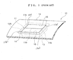
- An airbag cover 10 shown in Figure 1 corresponds to an interior cover of a vehicle, and is formed into a three-dimensionally covered plate.
- the airbag cover 10 has a three-layer structure; i.e. it includes a substrate 101 formed of hard polypropylene (PP) and having a thickness of 3 mm to 4 mm; a foam layer 102 layered over and bonded to the surface of the substrate 101, formed of foamed polypropylene, and having a thickness of 1.5 mm to 2 mm; and a surface layer 103 layered over and bonded to the surface of the foam layer 102, formed of thermoplastic polyolefin (TPO), and having a thickness of 0.6 mm to 1 mm.
- PP hard polypropylene
- TPO thermoplastic polyolefin
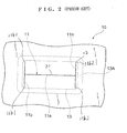
- a fracture groove 11 (indicated by a thick broken line) is formed on the reverse surface of the airbag cover 10 so as to enable an airbag to inflate and deploy to the outside of the airbag cover 10.
- the fracture groove 11 is composed of a single first fracture groove 11a extending in a longitudinal direction, and two second fracture grooves 11b connected to the opposite ends of the first fracture groove 11a and extending perpendicular to the first fracture groove 11a. These fracture grooves 11a and 11b form a generally H-like shape as viewed from above.
- the thickness of the airbag cover 10 is made smaller than the remaining regions through removal of the material from the reverse surface of the airbag cover 10, thereby to form hinge portions 15 of fracture-opening subsections 14 (indicated by two-dot chain lines), which are formed as a result of fracture of the fracture groove 11.
- the first and second fracture grooves 11a and 11b are formed by forming successive small holes (blind holes) 16 on the reverse surface of the airbag cover 10 through irradiation with an infrared laser beam having a beam diameter of 0.2 to 0.5 mm and a wavelength of 10.6 ⁇ m, in such a manner that the small holes pass through the substrate 101 and the foam layer 102 and reach the surface layer 103.
- a flange portion 13A of a frame 13 is bonded, by means of vibration welding or any other suitable process, to the reverse surface of the airbag cover 10.
- the frame 13 is formed of PP or TPO and has a size sufficient to surround the fracture groove 11.
- Reinforcement members (not shown) formed of PP or TPO are attached to the inner wall of the frame 13 so as to enhance the mechanical strength of a portion of the airbag cover 10 corresponding to the areas surrounded by the first fracture groove 11a, the second fracture grooves 11b, and the hinge portions 15. Portions of the reinforcement members are bonded, by means of vibration welding or any other suitable process, to the reverse surface of the airbag cover 10 in the above-mentioned areas.
- an airbag apparatus including an airbag, an airbag case, and an inflator, which are not shown, is attached to the frame 13.
- the thus-configured conventional airbag apparatus functions in the following manner.
- an impact force caused by the collision is detected by a sensor.
- a control unit including a CPU judges whether or not the detected impact force is equal to or greater than a predetermined value.
- the control unit judges that the impact force is equal to or greater than the predetermined value, the control unit issues a signal for causing the inflator to generate a high-pressure gas.
- the gas is fed to the airbag so as to promptly inflate the airbag.
- the inflating airbag presses, from inside, the airbag cover 10 in the regions surrounded by the fracture groove 11 and the hinges 15. As a result, the airbag cover 10 is ruptured along the first and second fracture grooves 11a and 11b.
- the fracture-opening subsections 14, formed as a result of the rupture of the airbag cover 10, are opened in the manner of a casement (French window), while being turned about hinge portions 15. As a result, the airbag inflates and deploys to the outside of the airbag cover 10.
- the inflated airbag supports the passenger at his/her chest or head, thereby protecting the passenger from the impact force of collision.
- the above-described conventional airbag cover 10 has the following drawback. Since the hinge portions 15 of the fracture-opening subsections 14, which are opened when the airbag cover 10 is ruptured along the fracture groove 11 upon inflation of the airbag, are thinner than the remaining portions, sink marks are produced on the substrate 101 at locations corresponding to the hinge portions 15, whereby sink marks or concave portions are formed on the outer surface of the airbag cover 10. As a result, the appearance of the airbag cover 10 is impaired, and the aesthetic effect is spoilt.
- the small holes 16, which constitute the first and second fracture grooves 11a and 11b are formed in such a manner that they pass through the substrate 101 and the foam layer 102 and reach the surface layer 103, as shown in Figure 3B, a high-temperature gas produced when a laser beam passes through the foam layer 102 melts neighbouring portions of the foam layer 102, so that a relatively large cavity is produced between the substrate 101 and the surface layer 103 around each hole 16.
- the conventional airbag cover 10 has the following problem.
- the foam layer 102 interposed between the substrate 101 and the surface layer 103 is compressed and deformed, and undulations are formed on the outer surface of the airbag cover 10, whereby the appearance of the airbag cover 10 is spoilt.
- Preferred embodiments of the present invention aim to provide an airbag cover which can prevent generation of sink marks or depressions on the surface of the cover during attachment of components of an airbag apparatus to the airbag cover.
- Another aim is to provide an airbag cover which secures reliable opening of fracture-opening subsections formed when the airbag cover is ruptured along the fracture grooves upon inflation of an airbag, thereby to facilitate deployment of the airbag toward the outside of the airbag cover.
- Still another aim is to provide an airbag apparatus for a vehicle which employs such an airbag cover.
- an airbag cover including a panel member for covering an airbag, the panel member comprising:
- the foam layer and the surface layer can be readily ruptured along the fracture groove.
- the opening of the fracture-opening subsections in the manner of a casement upon inflation of the airbag can be reliably performed in a well-balanced manner, and generation of a crack or breakage of the airbag cover, which would otherwise occur upon inflation of the airbag, can be prevented.
- the above-described effect can be achieved without fail through employment of reinforcement members, which reinforce the fracture-opening section from the reverse surface side of the plate member.
- reinforcement members which reinforce the fracture-opening section from the reverse surface side of the plate member.
- the fracture groove is not required to from in the foam layer and the surface layer of the panel member, no sink or depression is formed on the surface of the surface layer of the airbag cover. Therefore, the appearance of the airbag cover 22 is improved, and the aesthetic effect is improved.
- the fracture groove further includes two branch fracture groove sections extending from the opposite ends of the centre fracture groove section and assuming a V-like shape; and the first and second side fracture groove sections extend from distal ends of the V-shaped branch fracture groove sections.
- the fracture-opening subsections are ruptured along Y-shaped lines formed by the V-shaped branch fracture groove sections and the side fracture groove sections, so that the foam layer and the surface layer are ruptured along Y-shaped lines at the opposite ends of the centre fracture groove section. Therefore, the airbag can readily deploy without fail toward the outer side of the cover when the fracture-opening subsections open in the manner of a casement.
- the fracture groove and the hinge grooves are each composed of a plurality of small holes successively formed on the reverse surface of the substrate through irradiation with a laser beam.
- small holes constituting the fracture groove adjoin each other and have a depth corresponding to the thickness of the substrate or a depth slightly greater than the thickness of the substrate; and small holes constituting the hinge grooves are separated from each other and have a depth about half the thickness of the substrate.
- the centre fracture groove section may be offset from the boundary between the fracture-opening subsections toward one of the fracture-opening subsections, so that the area of the other fracture-opening subsection becomes larger than that of said one fracture-opening subsection.
- Such a configuration may enable the airbag to inflate and deploy to a direction inclined toward the fracture-opening subsection having a smaller area.
- a central portion of the centre fracture groove section with respect to its longitudinal direction has a depth slightly greater than the thickness of the substrate, and the remaining portions of the centre fracture groove section have a depth corresponding to the thickness of the substrate.
- the panel member when the airbag inflates, the panel member may start to rupture from the central portion of the centre rupture groove section, so that the panel member may be equally ruptured toward the left and right.
- each of the first and second hinge grooves has a depth of about half the depth of the fracture groove.
- the invention extends to an airbag apparatus for a vehicle, the apparatus comprising an airbag, an airbag cover according to any of the preceding aspects of the invention, an airbag case disposed behind the airbag cover and accommodating the airbag in a folded condition; an inflator for supplying a gas to the airbag so as to inflate and deploy the airbag; a frame formed of a resin and fixed to a reverse surface of the panel member of the airbag cover, the frame surrounding the fracture-opening section of the panel member which section supports the airbag case; and a pair of reinforcement members formed of a resin, the reinforcement member being supported by the frame and reinforcing the fracture-opening section from the reverse surface side thereof.
- the frame and the reinforcement members are vibration-welded to the reverse surface of the substrate before the foam layer and the surface layer are layered over and bonded to the substrate.
- the invention extends to a vehicle provided with such an airbag apparatus.
- an airbag apparatus employing an airbag cover is provided in front of a front passenger seat of an automobile.
- an airbag apparatus 100 for a vehicle includes an airbag cover (interior panel cover) 22, an airbag 24, an airbag case 26, a frame 28, a pair of reinforcement members 30, an inflator (not shown), etc.
- the airbag cover 22 is composed of a panel member 221 formed of a synthetic resin.
- the panel member 221 is formed into a three-dimensionally curved shape for covering the airbag 24 and covering an interior panel core (not shown) formed of a synthetic resin, and is secured to the interior panel core by means of, for example, self-tapping screws.
- the panel member 221 includes a substrate 221a formed of hard polypropylene (PP) and having a thickness of 3 mm to 4 mm; a foam layer 221b layered over and bonded to the surface of the substrate 221a, formed of foamed polypropylene, and having a thickness of 1.5 mm to 2 mm; and a surface layer 221 c layered over and bonded to the surface of the foam layer 221b, formed of thermoplastic polyolefin (TPO), and having a thickness of 0.6 mm to 1 mm.
- PP hard polypropylene
- TPO thermoplastic polyolefin
- the airbag 24 is accommodated in a folded condition within the airbag case 26 formed from a metallic plate material.
- the frame 28 holds the airbag case 26 and the reinforcement members 30 on the reverse surface side of the airbag cover 22.
- the frame 28 is formed of a highly elastic, polypropylene-based resin material containing a reinforcing material such as talc and glass fibre in an amount of 10 to 30% by weight, and assumes the form of a rectangular tube having a transverse cross-sectional area which corresponds to a rectangular fracture-opening section 221A of an area required to inflate and deploy the airbag 24.
- a joint flange 281 is integrally formed at the upper end of the frame 28 near the panel member 221, and is bonded, by means of vibration welding or any other suitable process, to the reverse surface of the substrate 221a of the panel member 221.
- the paired reinforcement members 30 reinforce the fracture-opening section 221A of the panel member 221 from the reverse side thereof, and are formed of a synthetic resin such as polypropylene (PP) or thermoplastic polyolefin (TPO).
- PP polypropylene
- TPO thermoplastic polyolefin
- Each of the reinforcement members 30 includes a support portion 301 coupled with the inner wall surface of the frame 28 via a dovetail; and a reinforcement portion 303 which is connected via a hinge portion 302 to the upper end of the support portion 301 in a bendable manner and is bonded to the reverse surface of the fracture-opening section 221A by means of vibration welding or any other suitable process.
- a plurality of hooks 261 are provided on the side wall portions of the airbag case 26 in the vicinity of an upper end opening 26a thereof, the side wall portions facing the support portions 301 of the corresponding reinforcement members 30.
- the hooks 261 are engaged with square holes 301a formed in the support portions 301 and holes 261a formed in the frame 28 to correspond to the holes 301a, whereby the airbag case 26 is secured to the frame 28.
- An inflator accommodation portion 262 is provided at the lower end of the airbag case 26 so as to accommodate an inflator (not shown) for supplying an inflation gas to the airbag 24.
- the airbag case 26 is fixed to a stationary member, such as a cross member 34, via a support member 32 and by means of a bolt and nut 36.
- a fracture groove 38 extending in the lateral direction is formed in the above-mentioned fracture-opening section 221A of the panel member 221.
- the fracture groove 38 is provided so as to form fracture-opening subsections 222a and 222b (see Figure 8) in the fracture-opening section 221A in such a manner that the fracture-opening subsections 222a and 222b can be opened in opposite directions (in the manner of a casement) when the fracture-opening section 221A is ruptured along the fracture groove 38 upon inflation of the airbag 24.
- the fracture groove 38 is a groove which is formed on the reverse surface of the substrate 221a to a depth corresponding to the thickness of the substrate 221a or a depth slightly greater than the thickness of the substrate 221a, so that the groove reaches the foam layer 221b.
- the fracture groove 38 which forms the fracture-opening subsections 222a and 222b openable in the manner of a casement, is composed of a centre fracture groove section 38a, two branch fracture groove sections 38b and 38c, and two pairs of side fracture groove sections 38d and 38e.
- the centre fracture groove section 38a extends straight in the longitudinal direction (the direction parallel to the longer sides), and divides the fracture-opening section 221A into two sections in the top-bottom direction (the direction parallel to the shorter sides).
- the branch fracture groove sections 38b and 38c extend from the opposite ends of the centre fracture groove section 38a, and assume a V-like shape.
- Each pair of side fracture groove sections 38d and 38e extends from the distal ends of the V-shaped branch fracture groove section 38b or 38c upward and downward, respectively, in Figure 5 (the direction parallel to the shorter sides).
- the centre fracture groove section 38a may be offset from the boundary between the fracture-opening subsections 222a and 222b toward the fracture-opening subsection 222b, so that the area of the fracture-opening subsection 222a becomes larger than that of the fracture-opening subsection 222b.
- Hinge grooves 39a and 39b for pivoting motion of the fracture-opening subsections 222a and 222b are formed on the fracture-opening section 221A such that the hinge groove 39a extends between the ends of the side fracture groove sections 38d, which are located on the upper side of the centre fracture groove section 38a in Figure 5, and the hinge groove 39b extends between the ends of the side fracture groove sections 38e, which are located on the lower side of the centre fracture groove section 38a in Figure 5.
- the hinge grooves 39a and 39b are grooves which are formed on the reverse surface of the substrate 221a to a depth about half the depth of the fracture groove 38.
- the fracture groove 38 is formed by forming successive small holes 40a, 40b along a predetermined line on the reverse surface of the panel member 221 through irradiation with a pulsed laser beam from the reverse surface of the substrate 221a, in such a manner that the small holes do not pass completely through the panel member 221, as shown in Figures 6A and 6B.
- the fracture groove 38 is formed by means of a plurality of the small holes 40a which adjoin each other and which have a depth corresponding to the thickness (3 to 4 mm) of the substrate 221a.
- the fracture groove 38 is formed by means of a plurality of the small holes 40b which adjoin each other and which pass through the substrate 221a and reach the foam layer 221b, so that the small holes 40b are not provided in the surface layer 221c.
- Each of the small holes 40a and 40b has a shape resembling a tip end of a bombshell - that is, each hole 40a and 40b may be of substantially circular cross-section that tapers towards a tip so that the transverse cross-sectional area, which is the maximum at the opening at the reverse surface of the substrate 221a, decreases toward the foam layer 221b.
- the small holes 40a and 40b having such a shape can be formed through control of the number of pulses or irradiation time of a laser beam emitted from a laser.
- hinge grooves 39a and 39b are formed by forming successive small holes 41a along predetermined lines on the reverse surface of the panel member 221 through irradiation with a pulsed laser beam from the reverse surface of the substrate 221a, in such a manner that the small holes do not pass completely through the panel member 221, as shown in Figure 7.
- each of the hinge grooves 39a and 39b is formed by means of a plurality of the small holes 41 a which are separated from each other and which have a depth ((3 to 4 mm) - 1.5 mm), which is about half the thickness (3 to 4 mm) of the substrate 221a.
- the small holes 41 a are formed at intervals of 0.5mm to 0.6mm by means of a laser cutting process.
- the branch fracture groove sections 38b and 38c and the side fracture groove sections 38d and 38e of the fracture groove 38 overlap the flange portion 281 of the frame 28, which is bonded to the reverse surface of the substrate 221a to surround the fracture-opening section 221A.
- the fracture groove 38 and the hinge grooves 39a and 39b may be formed by use of an infrared laser beam having a diameter of 0.2 to 0.5 mm and a wavelength of 10.6 ⁇ m.
- the thus-configured airbag apparatus 100 of the first embodiment functions in the following manner.
- an impact force caused by the collision is detected by a sensor (not shown).
- a control unit including a CPU judges whether or not the detected impact force is equal to or greater than a predetermined value.
- the control unit judges that the impact force is equal to or greater than the predetermined value, the control unit issues a signal for causing the inflator to generate a predetermined amount of gas.
- the gas is fed to the airbag 24 so as to promptly inflate the airbag 24.
- the foam layer 221b is ruptured by means of the rupture corner portions 43 and the impact force acing on the fracture-opening subsections 222a and 222b upon inflation of the airbag, and the surface layer 221c is expanded and ruptured along the fracture groove 38.
- the airbag 24 inflates and deploys toward the outside of the panel member 221 as the fracture-opening subsections 222a and 222b open in the opposite directions. Serving as a cushion, the inflated airbag 24 supports the passenger at his/her chest or head, thereby protecting the passenger from the impact force of collision.
- the fracture groove 38 which forms the fracture-opening subsections 222a and 222b in the fracture-opening section 221A of the panel member 221 composed of the substrate 221a, the foam layer 221b, and the surface layer 221c, is formed by successively forming the mutually adjacent small holes 40a or 40b along a predetermined line on the reverse surface of the panel member 221 by means of laser cutting from the reverse surface of the substrate 221a;
- the hinge groves 39a and 39b for pivoting motion of the fracture-opening subsections 222a and 222b are formed by successively forming the mutually separated small holes 41a along predetermined lines on the reverse surface of the panel member 221 by means of laser cutting from the reverse surface of the substrate 221a; and when the airbag 24 is inflated, the fracture-opening section of the panel member 221 is ruptured along the fracture groove 38, whereby the fracture-opening subsections 222a and 222b are caused to open in the manner of a casement
- the foam layer 221b and the surface layer 221c can be readily ruptured along the fracture groove 38.
- the opening of the fracture-opening subsections 222a and 222b in the manner of a casement upon inflation of the airbag 24 can be reliably performed in a well-balanced manner, and generation of a crack or breakage of the airbag cover 22, which would otherwise occur upon inflation of the airbag 24, can be prevented.
- the above-described effect can be achieved without fail through employment of the reinforcement members 30, which reinforce the fracture-opening section 221A from the reverse surface side of the substrate 221a.
- the reinforcement members 30, which reinforce the fracture-opening section 221A from the reverse surface side of the substrate 221a since fracture grooves are not required to be formed in the foam layer 221a and the surface layer 221c of the panel member 221, no sink mark or depression is formed on the surface of the surface layer 221c of the airbag cover 22. Therefore, the appearance of the airbag cover 22 is improved, and the aesthetic effect is improved.
- the fracture groove 38 is composed of the straight centre fracture groove section 38a, which divides the fracture-opening section 221A into two sections in the top-bottom direction (the direction parallel to the shorter sides); the branch fracture groove sections 38b and 38c, which extend from the opposite ends of the centre fracture groove section 38a, and assume a V-like shape; and the pairs of side fracture groove sections 38d and 38e, which extend from the distal ends of the V-shaped branch fracture groove sections 38b and 38c in opposite directions.
- the fracture-opening subsections 222a and 222b are ruptured along Y-shaped lines formed by the V-shaped branch fracture groove sections 38b and 38c and the side fracture groove sections 38d and 38e, so that the foam layer 221b and the surface layer 221c are ruptured along Y-shaped lines at the opposite ends of the centre fracture groove section 38a. Therefore, the airbag can readily deploy without fail toward the outer side of the cover when the fracture-opening subsections 222a and 222b open in the manner of a casement.
- the frame 28 and the reinforcement members 30 are vibration-welded to the reverse surface of the substrate 221 a before the foam layer 221b and the surface layer 221c are layered over and bonded to the substrate 221a, damage to the foam layer 221b of the panel member 221 may be prevented.
- the airbag 24 can reliably inflate and deploy toward a passenger in the front-passenger seat of the automobile, thereby to secure safety of the passenger.
- the branch fracture groove sections 38b and the side fracture groove sections 38d and 38e of the fracture groove 38 overlap the flange portion 281 of the frame 28, which is bonded to the reverse surface of the substrate 221a. Therefore, even when a pressing force is externally applied to the fracture-opening section 221A of the airbag cover 22, the fracture-opening section 221A hardly deforms; that is, the fracture-opening section 221A has increased strength.
- the frame 28 and the reinforcement members 30 are each formed of a resin material, and are vibration-welded to the reverse surface of the panel member 221. Therefore, the productivity of the airbag cover 22 can be improved, and production cost can be reduced.
- the fracture groove 38 and the hinge grooves 39a and 39b are not limited to grooves composed of small holes formed by means of laser cutting as shown in Figures 6A, 6B, and 7, and may be grooves which are continuously or intermittently formed on the back surface of the substrate 221a of the panel member 221 by use of a cutting tool or the like.
- the second embodiment differs from the first embodiment in the depth of the centre fracture groove section 38a, which divides the fracture-opening section into two subsections.
- a central portion C of the centre fracture groove section 38a with respect to the longitudinal direction is composed of small holes 40b having a depth slightly greater than the thickness of the substrate 221a so that the small holes 40b reach the foam layer 221b, and right-hand and left-hand end portions D of the centre fracture groove section 38a with respect to the longitudinal direction are each composed of small holes 40a having a depth corresponding to the thickness of the substrate 221a. Since other structural components are identical to those of the first embodiment, they are denoted by the same reference numerals, and their description is not repeated.
- the rupture of the panel member 221 starts from the central portion of the centre rupture groove section, so that the panel member 221 is equally ruptured toward the left and right.
- the method of bonding the frame 28 and the reinforcement members 30 to the reverse surface of the substrate 221a is not limited to vibration welding as mentioned in the above-described embodiments, and adhesive may be used to bond the frame 28 and the reinforcement members 30 to the reverse surface of the substrate 221a.
- Embodiments of the present invention can be applied to airbag apparatuses from which the reinforcement members 30 are omitted.
Landscapes
- Engineering & Computer Science (AREA)
- Mechanical Engineering (AREA)
- Air Bags (AREA)
- Instrument Panels (AREA)
Abstract
Description
- The present invention relates to airbag apparatus for a vehicle and to an airbag cover for covering airbag apparatus. Preferred embodiments of the invention relate to an airbag cover which has a surface layer and a foam layer and which has a fracture groove for deployment of an airbag and to an airbag apparatus for a vehicle which utilizes such an airbag cover.
- The term "fracture groove" used in relation to the present invention refers to a weakened portion or a fracture portion for fracture opening which is composed of successive holes formed on the reverse or inside surface of an interior panel of a vehicle through irradiation with a laser beam generated from laser generation means in the form of laser pulses, or a groove continuously or intermittently formed on the reverse or inside surface of the interior panel by use of a cutting tool or the like.
- There has been known an airbag apparatus for a vehicle for protecting a person in a vehicle such as an automobile; for example, a driver or a passenger sitting in the front passenger seat, from impact upon head-on or side collision of the vehicle. Such an airbag apparatus includes an airbag, an airbag case for accommodating the airbag folded such that the airbag can easily inflate and deploy, and an inflator for inflating the folded airbag within a short period of time. In particular, an airbag apparatus which is used for the front passenger seat is disposed behind an airbag cover, which forms an interior panel or the like. When the automobile decelerates suddenly because of, for example, a collision, the inflator is operated so as to rapidly inflate the airbag, thereby to rupture and open the interior panel along the fracture groove and cause the airbag to inflate and deploy toward the outside of the airbag cover. Thus, the airbag apparatus protects the passenger from impact of the collision.
- The fracture groove for causing the airbag of the airbag apparatus to inflate and deploy toward the outside of the airbag cover is formed by forming successive small holes on the reverse surface of the interior panel through irradiation with a laser beam (see, for example,
Japanese Patent Application Laid-Open (kokai) No. 2005-22453 - A conventional airbag apparatus for a vehicle will now be described with reference to Figure 1, Figure 2, and Figures 3A and 3B of the accompanying diagrammatic drawings.
- An
airbag cover 10 shown in Figure 1 corresponds to an interior cover of a vehicle, and is formed into a three-dimensionally covered plate. As shown in Figures 3A and 3B, theairbag cover 10 has a three-layer structure; i.e. it includes asubstrate 101 formed of hard polypropylene (PP) and having a thickness of 3 mm to 4 mm; afoam layer 102 layered over and bonded to the surface of thesubstrate 101, formed of foamed polypropylene, and having a thickness of 1.5 mm to 2 mm; and asurface layer 103 layered over and bonded to the surface of thefoam layer 102, formed of thermoplastic polyolefin (TPO), and having a thickness of 0.6 mm to 1 mm. - As shown in Figures 1 and 2, a fracture groove 11 (indicated by a thick broken line) is formed on the reverse surface of the
airbag cover 10 so as to enable an airbag to inflate and deploy to the outside of theairbag cover 10. Thefracture groove 11 is composed of a singlefirst fracture groove 11a extending in a longitudinal direction, and twosecond fracture grooves 11b connected to the opposite ends of thefirst fracture groove 11a and extending perpendicular to thefirst fracture groove 11a. These fracture grooves 11a and 11b form a generally H-like shape as viewed from above. - In elongated regions between the opposite ends 11b1 of the left-hand
second fracture groove 11b and the opposite ends 11b2 of the right-handsecond fracture groove 11b, the thickness of theairbag cover 10 is made smaller than the remaining regions through removal of the material from the reverse surface of theairbag cover 10, thereby to form hingeportions 15 of fracture-opening subsections 14 (indicated by two-dot chain lines), which are formed as a result of fracture of thefracture groove 11. - As shown in Figures 3A and 3B, the first and
second fracture grooves airbag cover 10 through irradiation with an infrared laser beam having a beam diameter of 0.2 to 0.5 mm and a wavelength of 10.6 µm, in such a manner that the small holes pass through thesubstrate 101 and thefoam layer 102 and reach thesurface layer 103. - A
flange portion 13A of aframe 13 is bonded, by means of vibration welding or any other suitable process, to the reverse surface of theairbag cover 10. Theframe 13 is formed of PP or TPO and has a size sufficient to surround thefracture groove 11. - Reinforcement members (not shown) formed of PP or TPO are attached to the inner wall of the
frame 13 so as to enhance the mechanical strength of a portion of theairbag cover 10 corresponding to the areas surrounded by thefirst fracture groove 11a, thesecond fracture grooves 11b, and thehinge portions 15. Portions of the reinforcement members are bonded, by means of vibration welding or any other suitable process, to the reverse surface of theairbag cover 10 in the above-mentioned areas. Moreover, an airbag apparatus including an airbag, an airbag case, and an inflator, which are not shown, is attached to theframe 13. - The thus-configured conventional airbag apparatus functions in the following manner. Upon collision of the vehicle, an impact force caused by the collision is detected by a sensor. A control unit including a CPU judges whether or not the detected impact force is equal to or greater than a predetermined value. When the control unit judges that the impact force is equal to or greater than the predetermined value, the control unit issues a signal for causing the inflator to generate a high-pressure gas. The gas is fed to the airbag so as to promptly inflate the airbag. The inflating airbag presses, from inside, the
airbag cover 10 in the regions surrounded by thefracture groove 11 and thehinges 15. As a result, theairbag cover 10 is ruptured along the first andsecond fracture grooves - The fracture-
opening subsections 14, formed as a result of the rupture of theairbag cover 10, are opened in the manner of a casement (French window), while being turned abouthinge portions 15. As a result, the airbag inflates and deploys to the outside of theairbag cover 10. - Serving as a cushion, the inflated airbag supports the passenger at his/her chest or head, thereby protecting the passenger from the impact force of collision.
- However, the above-described
conventional airbag cover 10 has the following drawback. Since thehinge portions 15 of the fracture-openingsubsections 14, which are opened when theairbag cover 10 is ruptured along thefracture groove 11 upon inflation of the airbag, are thinner than the remaining portions, sink marks are produced on thesubstrate 101 at locations corresponding to thehinge portions 15, whereby sink marks or concave portions are formed on the outer surface of theairbag cover 10. As a result, the appearance of theairbag cover 10 is impaired, and the aesthetic effect is spoilt. - Moreover, in the
conventional airbag cover 10, since thesmall holes 16, which constitute the first andsecond fracture grooves substrate 101 and thefoam layer 102 and reach thesurface layer 103, as shown in Figure 3B, a high-temperature gas produced when a laser beam passes through thefoam layer 102 melts neighbouring portions of thefoam layer 102, so that a relatively large cavity is produced between thesubstrate 101 and thesurface layer 103 around eachhole 16. - Therefore, the
conventional airbag cover 10 has the following problem. When the flange portion of the frame and the reinforcement members are vibration-welded to the reverse surface of theairbag cover 10, thefoam layer 102 interposed between thesubstrate 101 and thesurface layer 103 is compressed and deformed, and undulations are formed on the outer surface of theairbag cover 10, whereby the appearance of theairbag cover 10 is spoilt. - Preferred embodiments of the present invention aim to provide an airbag cover which can prevent generation of sink marks or depressions on the surface of the cover during attachment of components of an airbag apparatus to the airbag cover.
- Another aim is to provide an airbag cover which secures reliable opening of fracture-opening subsections formed when the airbag cover is ruptured along the fracture grooves upon inflation of an airbag, thereby to facilitate deployment of the airbag toward the outside of the airbag cover.
- Still another aim is to provide an airbag apparatus for a vehicle which employs such an airbag cover.
- According to one aspect of the present invention, there is provided an airbag cover including a panel member for covering an airbag, the panel member comprising:
- a substrate formed of a resin;
- a foam layer formed of a resin and layered over and bonded to a surface of the substrate; and
- a surface layer layered over and bonded to a surface of the foam layer:
wherein:- the panel member has a fracture-opening section of an area required for inflation and deployment of the airbag;
- a fracture groove is formed in the fracture-opening section so as to define two fracture-opening subsections which can be opened in the manner of a casement, the fracture groove being formed on a reverse surface of the substrate and having a depth corresponding to the thickness of the substrate or a depth slightly greater than the thickness of the substrate;
- the fracture groove is composed of a straight centre fracture groove section for dividing the fracture-opening section into the fracture-opening subsections, first side fracture groove sections extending from the opposite ends of the centre fracture groove section in a first direction perpendicularly to the centre fracture groove section, and second side fracture groove sections extending from the opposite ends of the centre fracture groove section in a second direction opposite the first direction; and
- first and second hinge grooves for pivotal motion of the fracture-opening subsections are formed on the reverse surface of the substrate such that the first hinge groove extends between the ends of the first side fracture groove sections and the second hinge groove extends between the ends of the second side fracture groove sections, each of the first and second hinge grooves having a depth less than that of the fracture groove.
- In preferred embodiments of the invention, by virtue of the above-described configuration, even though the fracture groove is not formed in the foam layer and the surface layer, by means of rupture corner portions of the substrate ruptured along the fracture groove and the impact force acting on the fracture-opening subsections upon inflation of the airbag, the foam layer and the surface layer can be readily ruptured along the fracture groove. In addition, the opening of the fracture-opening subsections in the manner of a casement upon inflation of the airbag can be reliably performed in a well-balanced manner, and generation of a crack or breakage of the airbag cover, which would otherwise occur upon inflation of the airbag, can be prevented. In particular, the above-described effect can be achieved without fail through employment of reinforcement members, which reinforce the fracture-opening section from the reverse surface side of the plate member. Moreover, since the fracture groove is not required to from in the foam layer and the surface layer of the panel member, no sink or depression is formed on the surface of the surface layer of the airbag cover. Therefore, the appearance of the
airbag cover 22 is improved, and the aesthetic effect is improved. - Preferably, the fracture groove further includes two branch fracture groove sections extending from the opposite ends of the centre fracture groove section and assuming a V-like shape; and the first and second side fracture groove sections extend from distal ends of the V-shaped branch fracture groove sections.
- In such preferred embodiments of the invention, at the opposite ends of the centre fracture groove section, the fracture-opening subsections are ruptured along Y-shaped lines formed by the V-shaped branch fracture groove sections and the side fracture groove sections, so that the foam layer and the surface layer are ruptured along Y-shaped lines at the opposite ends of the centre fracture groove section. Therefore, the airbag can readily deploy without fail toward the outer side of the cover when the fracture-opening subsections open in the manner of a casement.
- Preferably, the fracture groove and the hinge grooves are each composed of a plurality of small holes successively formed on the reverse surface of the substrate through irradiation with a laser beam.
- Preferably, small holes constituting the fracture groove adjoin each other and have a depth corresponding to the thickness of the substrate or a depth slightly greater than the thickness of the substrate; and small holes constituting the hinge grooves are separated from each other and have a depth about half the thickness of the substrate.
- The centre fracture groove section may be offset from the boundary between the fracture-opening subsections toward one of the fracture-opening subsections, so that the area of the other fracture-opening subsection becomes larger than that of said one fracture-opening subsection.
- Such a configuration may enable the airbag to inflate and deploy to a direction inclined toward the fracture-opening subsection having a smaller area.
- Preferably, a central portion of the centre fracture groove section with respect to its longitudinal direction has a depth slightly greater than the thickness of the substrate, and the remaining portions of the centre fracture groove section have a depth corresponding to the thickness of the substrate.
- In such a case, when the airbag inflates, the panel member may start to rupture from the central portion of the centre rupture groove section, so that the panel member may be equally ruptured toward the left and right.
- Preferably, each of the first and second hinge grooves has a depth of about half the depth of the fracture groove.
- The invention extends to an airbag apparatus for a vehicle, the apparatus comprising an airbag, an airbag cover according to any of the preceding aspects of the invention, an airbag case disposed behind the airbag cover and accommodating the airbag in a folded condition; an inflator for supplying a gas to the airbag so as to inflate and deploy the airbag; a frame formed of a resin and fixed to a reverse surface of the panel member of the airbag cover, the frame surrounding the fracture-opening section of the panel member which section supports the airbag case; and a pair of reinforcement members formed of a resin, the reinforcement member being supported by the frame and reinforcing the fracture-opening section from the reverse surface side thereof.
- Preferably, the frame and the reinforcement members are vibration-welded to the reverse surface of the substrate before the foam layer and the surface layer are layered over and bonded to the substrate.
- The invention extends to a vehicle provided with such an airbag apparatus.
- For a better understanding of the invention, and to show how embodiments of the same may be carried into effect, reference will now be made, by way of example, to the accompanying diagrammatic drawings, in which:
- Figure 1 is a perspective view of a conventional airbag cover;
- Figure 2 is a plan view of the airbag cover shown in Figure 1;
- Figure 3A is an enlarged cross-sectional view of the airbag cover taken along line 3-3 of Figure 2;
- Figure 3B is an enlarged view of a portion of Figure 3A;
- Figure 4 is a vertical sectional view of a main portion of an airbag apparatus for a vehicle which employs an airbag cover according to one example of a first embodiment of the present invention;
- Figure 5 is a plan view of the airbag apparatus of Figure 4 as viewed in the direction of
arrow 5; - Figure 6A is an enlarged cross-sectional view of the airbag cover taken along line 6-6 of Figure 5;
- Figure 6B is an enlarged cross-sectional view of the airbag cover taken along line 6-6 of Figure 5;
- Figure 7 is an enlarged cross-sectional view of the airbag cover taken along line 7-7 of Figure 5;
- Figure 8 is a perspective view of the airbag cover according to the first embodiment, showing its fracture-opening subsections;
- Figure 9 is an explanatory view of the airbag cover according to the first embodiment showing the relation between the fracture-opening subsections and the surface layer at the time when the fracture-opening subsections are opened; and
- Figure 10 is a vertical sectional view of a main portion of an airbag apparatus for a vehicle which employs an airbag cover according to an example of a second embodiment of the present invention.
- In the figures, like references denote like or corresponding parts.
- In the following described examples of the present invention, an airbag apparatus employing an airbag cover is provided in front of a front passenger seat of an automobile.
- An airbag cover according to the first embodiment and an airbag apparatus employing the airbag cover will be described with reference to Figures 4 to Figure 8.
- As shown in Figure 4, an
airbag apparatus 100 for a vehicle includes an airbag cover (interior panel cover) 22, anairbag 24, anairbag case 26, aframe 28, a pair ofreinforcement members 30, an inflator (not shown), etc. - The airbag cover 22 is composed of a
panel member 221 formed of a synthetic resin. Thepanel member 221 is formed into a three-dimensionally curved shape for covering theairbag 24 and covering an interior panel core (not shown) formed of a synthetic resin, and is secured to the interior panel core by means of, for example, self-tapping screws. - As shown in Figures 4, 6, and 7, the
panel member 221 includes asubstrate 221a formed of hard polypropylene (PP) and having a thickness of 3 mm to 4 mm; afoam layer 221b layered over and bonded to the surface of thesubstrate 221a, formed of foamed polypropylene, and having a thickness of 1.5 mm to 2 mm; and asurface layer 221 c layered over and bonded to the surface of thefoam layer 221b, formed of thermoplastic polyolefin (TPO), and having a thickness of 0.6 mm to 1 mm. - As shown in Figure 4, the
airbag 24 is accommodated in a folded condition within theairbag case 26 formed from a metallic plate material. - As shown in Figures 4 and 5, the
frame 28 holds theairbag case 26 and thereinforcement members 30 on the reverse surface side of theairbag cover 22. Theframe 28 is formed of a highly elastic, polypropylene-based resin material containing a reinforcing material such as talc and glass fibre in an amount of 10 to 30% by weight, and assumes the form of a rectangular tube having a transverse cross-sectional area which corresponds to a rectangular fracture-opening section 221A of an area required to inflate and deploy theairbag 24. Ajoint flange 281 is integrally formed at the upper end of theframe 28 near thepanel member 221, and is bonded, by means of vibration welding or any other suitable process, to the reverse surface of thesubstrate 221a of thepanel member 221. - As shown in Figures 4 and 5, the paired
reinforcement members 30 reinforce the fracture-opening section 221A of thepanel member 221 from the reverse side thereof, and are formed of a synthetic resin such as polypropylene (PP) or thermoplastic polyolefin (TPO). Each of thereinforcement members 30 includes asupport portion 301 coupled with the inner wall surface of theframe 28 via a dovetail; and areinforcement portion 303 which is connected via ahinge portion 302 to the upper end of thesupport portion 301 in a bendable manner and is bonded to the reverse surface of the fracture-opening section 221A by means of vibration welding or any other suitable process. - A plurality of
hooks 261 are provided on the side wall portions of theairbag case 26 in the vicinity of an upper end opening 26a thereof, the side wall portions facing thesupport portions 301 of the correspondingreinforcement members 30. Thehooks 261 are engaged withsquare holes 301a formed in thesupport portions 301 andholes 261a formed in theframe 28 to correspond to theholes 301a, whereby theairbag case 26 is secured to theframe 28. Aninflator accommodation portion 262 is provided at the lower end of theairbag case 26 so as to accommodate an inflator (not shown) for supplying an inflation gas to theairbag 24. Theairbag case 26 is fixed to a stationary member, such as across member 34, via asupport member 32 and by means of a bolt andnut 36. - As shown in Figure 5, a
fracture groove 38 extending in the lateral direction is formed in the above-mentioned fracture-opening section 221A of thepanel member 221. - The
fracture groove 38 is provided so as to form fracture-openingsubsections opening section 221A in such a manner that the fracture-openingsubsections opening section 221A is ruptured along thefracture groove 38 upon inflation of theairbag 24. As shown in Figures 6A and 6B, thefracture groove 38 is a groove which is formed on the reverse surface of thesubstrate 221a to a depth corresponding to the thickness of thesubstrate 221a or a depth slightly greater than the thickness of thesubstrate 221a, so that the groove reaches thefoam layer 221b. - As shown in Figure 5, the
fracture groove 38, which forms the fracture-openingsubsections fracture groove section 38a, two branchfracture groove sections fracture groove sections fracture groove section 38a extends straight in the longitudinal direction (the direction parallel to the longer sides), and divides the fracture-opening section 221A into two sections in the top-bottom direction (the direction parallel to the shorter sides). The branchfracture groove sections fracture groove section 38a, and assume a V-like shape. Each pair of sidefracture groove sections fracture groove section - The centre
fracture groove section 38a may be offset from the boundary between the fracture-openingsubsections opening subsection 222b, so that the area of the fracture-opening subsection 222a becomes larger than that of the fracture-opening subsection 222b. -
Hinge grooves subsections opening section 221A such that thehinge groove 39a extends between the ends of the sidefracture groove sections 38d, which are located on the upper side of the centrefracture groove section 38a in Figure 5, and thehinge groove 39b extends between the ends of the sidefracture groove sections 38e, which are located on the lower side of the centrefracture groove section 38a in Figure 5. As shown in Figure 7, thehinge grooves substrate 221a to a depth about half the depth of thefracture groove 38. - The
fracture groove 38 is formed by forming successivesmall holes panel member 221 through irradiation with a pulsed laser beam from the reverse surface of thesubstrate 221a, in such a manner that the small holes do not pass completely through thepanel member 221, as shown in Figures 6A and 6B. - In the example shown in Figure 6A, the
fracture groove 38 is formed by means of a plurality of thesmall holes 40a which adjoin each other and which have a depth corresponding to the thickness (3 to 4 mm) of thesubstrate 221a. - In the example shown in Figure 6B, the
fracture groove 38 is formed by means of a plurality of thesmall holes 40b which adjoin each other and which pass through thesubstrate 221a and reach thefoam layer 221b, so that thesmall holes 40b are not provided in thesurface layer 221c. - Each of the
small holes hole substrate 221a, decreases toward thefoam layer 221b. Thesmall holes - The above-described
hinge grooves small holes 41a along predetermined lines on the reverse surface of thepanel member 221 through irradiation with a pulsed laser beam from the reverse surface of thesubstrate 221a, in such a manner that the small holes do not pass completely through thepanel member 221, as shown in Figure 7. - That is, as shown in Figure 7, each of the
hinge grooves small holes 41 a which are separated from each other and which have a depth ((3 to 4 mm) - 1.5 mm), which is about half the thickness (3 to 4 mm) of thesubstrate 221a. For example, thesmall holes 41 a are formed at intervals of 0.5mm to 0.6mm by means of a laser cutting process. - As shown in Figure 5, the branch
fracture groove sections fracture groove sections fracture groove 38 overlap theflange portion 281 of theframe 28, which is bonded to the reverse surface of thesubstrate 221a to surround the fracture-opening section 221A. - The
fracture groove 38 and thehinge grooves - The thus-configured
airbag apparatus 100 of the first embodiment functions in the following manner. Upon collision of the vehicle, an impact force caused by the collision is detected by a sensor (not shown). A control unit including a CPU judges whether or not the detected impact force is equal to or greater than a predetermined value. When the control unit judges that the impact force is equal to or greater than the predetermined value, the control unit issues a signal for causing the inflator to generate a predetermined amount of gas. The gas is fed to theairbag 24 so as to promptly inflate theairbag 24. - When the
airbag 24 promptly inflates, pressure generated at the beginning of the inflation acts on the fracture-opening section 221A via thereinforcement portions 303 of thereinforcement members 30. As a result, the fracture-opening section 221A is ruptured along thefracture groove 38, and the fracture-openingsubsections panel member 221 in the manner of a casement as shown in Figure 8, while being turned abouthinge grooves corner portions 43 of thesubstrate 221a ruptured along thefracture groove 38 are pressed against thesurface layer 221c. Therefore, thefoam layer 221b is ruptured by means of therupture corner portions 43 and the impact force acing on the fracture-openingsubsections surface layer 221c is expanded and ruptured along thefracture groove 38. - Simultaneously with this, the
airbag 24 inflates and deploys toward the outside of thepanel member 221 as the fracture-openingsubsections inflated airbag 24 supports the passenger at his/her chest or head, thereby protecting the passenger from the impact force of collision. - In the
airbag apparatus 100 according to the first embodiment, thefracture groove 38, which forms the fracture-openingsubsections opening section 221A of thepanel member 221 composed of thesubstrate 221a, thefoam layer 221b, and thesurface layer 221c, is formed by successively forming the mutually adjacentsmall holes panel member 221 by means of laser cutting from the reverse surface of thesubstrate 221a; thehinge groves subsections small holes 41a along predetermined lines on the reverse surface of thepanel member 221 by means of laser cutting from the reverse surface of thesubstrate 221a; and when theairbag 24 is inflated, the fracture-opening section of thepanel member 221 is ruptured along thefracture groove 38, whereby the fracture-openingsubsections hinge grooves foam layer 221b or thesurface layer 221c, by means of therupture corner portions 43 of thesubstrate 221a ruptured along thefracture groove 38 and the impact force acing on the fracture-openingsubsections foam layer 221b and thesurface layer 221c can be readily ruptured along thefracture groove 38. In addition, the opening of the fracture-openingsubsections airbag 24 can be reliably performed in a well-balanced manner, and generation of a crack or breakage of theairbag cover 22, which would otherwise occur upon inflation of theairbag 24, can be prevented. - In particular, the above-described effect can be achieved without fail through employment of the
reinforcement members 30, which reinforce the fracture-opening section 221A from the reverse surface side of thesubstrate 221a. Moreover, since fracture grooves are not required to be formed in thefoam layer 221a and thesurface layer 221c of thepanel member 221, no sink mark or depression is formed on the surface of thesurface layer 221c of theairbag cover 22. Therefore, the appearance of theairbag cover 22 is improved, and the aesthetic effect is improved. - In the first embodiment, the
fracture groove 38 is composed of the straight centrefracture groove section 38a, which divides the fracture-opening section 221A into two sections in the top-bottom direction (the direction parallel to the shorter sides); the branchfracture groove sections fracture groove section 38a, and assume a V-like shape; and the pairs of sidefracture groove sections fracture groove sections fracture groove section 38a, the fracture-openingsubsections fracture groove sections fracture groove sections foam layer 221b and thesurface layer 221c are ruptured along Y-shaped lines at the opposite ends of the centrefracture groove section 38a. Therefore, the airbag can readily deploy without fail toward the outer side of the cover when the fracture-openingsubsections - In the first embodiment, if the
frame 28 and thereinforcement members 30 are vibration-welded to the reverse surface of thesubstrate 221 a before thefoam layer 221b and thesurface layer 221c are layered over and bonded to thesubstrate 221a, damage to thefoam layer 221b of thepanel member 221 may be prevented. - In the first embodiment, when the centre
fracture groove section 38a is offset from the boundary between the fracture-openingsubsections opening subsection 222b, so that the area of the fracture-opening subsection 222a becomes larger than that of the fracture-opening subsection 222b, theairbag 24 can reliably inflate and deploy toward a passenger in the front-passenger seat of the automobile, thereby to secure safety of the passenger. - In the first embodiment, as shown in Figure 5, the branch
fracture groove sections 38b and the sidefracture groove sections fracture groove 38 overlap theflange portion 281 of theframe 28, which is bonded to the reverse surface of thesubstrate 221a. Therefore, even when a pressing force is externally applied to the fracture-opening section 221A of theairbag cover 22, the fracture-opening section 221A hardly deforms; that is, the fracture-opening section 221A has increased strength. - In the first embodiment, the
frame 28 and thereinforcement members 30 are each formed of a resin material, and are vibration-welded to the reverse surface of thepanel member 221. Therefore, the productivity of theairbag cover 22 can be improved, and production cost can be reduced. - Notably, the
fracture groove 38 and thehinge grooves substrate 221a of thepanel member 221 by use of a cutting tool or the like. - Another example of the present invention will now be described with reference to Figure 10, which corresponds to Figures 6A and 6B.
- The second embodiment differs from the first embodiment in the depth of the centre
fracture groove section 38a, which divides the fracture-opening section into two subsections. - That is, a central portion C of the centre
fracture groove section 38a with respect to the longitudinal direction is composed ofsmall holes 40b having a depth slightly greater than the thickness of thesubstrate 221a so that thesmall holes 40b reach thefoam layer 221b, and right-hand and left-hand end portions D of the centrefracture groove section 38a with respect to the longitudinal direction are each composed ofsmall holes 40a having a depth corresponding to the thickness of thesubstrate 221a. Since other structural components are identical to those of the first embodiment, they are denoted by the same reference numerals, and their description is not repeated. - In the second embodiment, when the airbag inflates, the rupture of the
panel member 221 starts from the central portion of the centre rupture groove section, so that thepanel member 221 is equally ruptured toward the left and right. - The method of bonding the
frame 28 and thereinforcement members 30 to the reverse surface of thesubstrate 221a is not limited to vibration welding as mentioned in the above-described embodiments, and adhesive may be used to bond theframe 28 and thereinforcement members 30 to the reverse surface of thesubstrate 221a. - Embodiments of the present invention can be applied to airbag apparatuses from which the
reinforcement members 30 are omitted. - Obviously, numerous modifications and variations of the present invention are possible in light of the above teachings. It is therefore to be understood that other examples of the present invention may be practiced otherwise than as specifically described herein.
- In this specification, the verb "comprise" has its normal dictionary meaning, to denote non-exclusive inclusion. That is, use of the word "comprise" (or any of its derivatives) to include one feature or more, does not exclude the possibility of also including further features.
- The reader's attention is directed to all and any priority documents identified in connection with this application and to all and any papers and documents which are filed concurrently with or previous to this specification in connection with this application and which are open to public inspection with this specification, and the contents of all such papers and documents are incorporated herein by reference.
- All of the features disclosed in this specification (including any accompanying claims, abstract and drawings), and/or all of the steps of any method or process so disclosed, may be combined in any combination, except combinations where at least some of such features and/or steps are mutually exclusive.
- Each feature disclosed in this specification (including any accompanying claims, abstract and drawings), may be replaced by alternative features serving the same, equivalent or similar purpose, unless expressly stated otherwise. Thus, unless expressly stated otherwise, each feature disclosed is one example only of a generic series of equivalent or similar features.
- The invention is not restricted to the details of the foregoing embodiment(s). The invention extends to any novel one, or any novel combination, of the features disclosed in this specification (including any accompanying claims, abstract and drawings), or to any novel one, or any novel combination, of the steps of any method or process so disclosed.
Claims (10)
- An airbag cover (22) including a panel member (221) for covering an airbag (24), the panel member (221) comprising:a substrate (221a) formed of a resin;a foam layer (221b) formed of a resin and layered over and bonded to a surface of the substrate (221a); anda surface layer (221c) layered over and bonded to a surface of the foam layer (221b): wherein:the panel member (221) has a fracture-opening section (221A) of an area required for inflation and deployment of the airbag (24);a fracture groove (38) is formed in the fracture-opening section (221A) so as to define two fracture-opening subsections (222a, 222b) which can be opened in the manner of a casement, the fracture groove (38) being formed on a reverse surface of the substrate (221a) and having a depth corresponding to the thickness of the substrate (221a) or a depth slightly greater than the thickness of the substrate (221a);the fracture groove (38) is composed of a straight centre fracture groove section (38a) for dividing the fracture-opening section (221A) into the fracture-opening subsections (222a, 222b), first side fracture groove sections (38d) extending from the opposite ends of the centre fracture groove section (38a) in a first direction perpendicularly to the centre fracture groove section (38a), and second side fracture groove sections (38e) extending from the opposite ends of the centre fracture groove section (38a) in a second direction opposite the first direction; andfirst and second hinge grooves (39a, 39b) for pivotal motion of the fracture-opening subsections (222a, 222b) are formed on the reverse surface of the substrate (221a) such that the first hinge groove (39a) extends between the ends of the first side fracture groove sections (38d) and the second hinge groove (39b) extends between the ends of the second side fracture groove sections (38e), each of the first and second hinge grooves (39a, 39b) having a depth less than that of the fracture groove (38).
- An airbag cover (22) according to claim 1, wherein the fracture groove (38) further includes two branch fracture groove sections (38b, 38c) extending from the opposite ends of the centre fracture groove section (38a) and assuming a V-like shape; and the first and second side fracture groove sections (38d, 38e) extend from distal ends of the V-shaped branch fracture groove sections (38b, 38c).
- An airbag cover (22) according to claim 1 or 2, wherein the fracture groove (38) and the hinge grooves (39a, 39b) are each composed of a plurality of small holes (40a, 40b, 41a) successively formed on the reverse surface of the substrate (221a) through irradiation with a laser beam.
- An airbag cover (22) according to claim 1, 2 or 3, wherein small holes (40a, 40b) constituting the fracture groove (38) adjoin each other and have a depth corresponding to the thickness of the substrate (221a) or a depth slightly greater than the thickness of the substrate (221a); and small holes (41a) constituting the hinge grooves (39a, 39b) are separated from each other and have a depth about half the thickness of the substrate (221a).
- An airbag cover (22) according to any of the preceding claims, wherein the centre fracture groove section (38a) is offset from the boundary between the fracture-opening subsections (222a, 222b) toward one of the fracture-opening subsections (222a, 222b), so that the area of the other fracture-opening subsection becomes larger than that of said one fracture-opening subsection.
- An airbag cover (22) according to any of the preceding claims, wherein a central portion (C) of the centre fracture groove section (38a) with respect to its longitudinal direction has a depth slightly greater than the thickness of the substrate (221a), and the remaining portions (D) of the centre fracture groove section (38a) have a depth corresponding to the thickness of the substrate (221a).
- An airbag cover (22) according to any of the preceding claims, wherein each of the first and second hinge grooves (39a, 39b) has a depth of about half the depth of the fracture groove (38).
- An airbag apparatus for a vehicle, the apparatus comprising an airbag (24), an airbag cover (22) according to any of the preceding claims, an airbag case (26) disposed behind the airbag cover (22) and accommodating the airbag (24) in a folded condition; an inflator for supplying a gas to the airbag (24) so as to inflate and deploy the airbag (24); a frame (28) formed of a resin and fixed to a reverse surface of the panel member (221) of the airbag cover (22), the frame surrounding the fracture-opening section (221A) of the panel member (221) which section supports the airbag case; and a pair of reinforcement members (30) formed of a resin, the reinforcement members (30) being supported by the frame (28) and reinforcing the fracture-opening section (221A) from the reverse surface side thereof.
- An airbag apparatus according to claim 8, wherein the frame (28) and the reinforcement members (30) are vibration-welded to the reverse surface of the substrate (221a) before the foam layer (221b) and the surface layer (221c) are layered over and bonded to the substrate (221a).
- A vehicle provided with an airbag apparatus according to claim 8 or 9.
Applications Claiming Priority (1)
| Application Number | Priority Date | Filing Date | Title |
|---|---|---|---|
| JP2005160249A JP4831999B2 (en) | 2005-05-31 | 2005-05-31 | VEHICLE AIRBACK DEVICE AND AIRBACK COVER |
Publications (3)
| Publication Number | Publication Date |
|---|---|
| EP1738970A2 true EP1738970A2 (en) | 2007-01-03 |
| EP1738970A3 EP1738970A3 (en) | 2008-03-12 |
| EP1738970B1 EP1738970B1 (en) | 2011-05-18 |
Family
ID=36928623
Family Applications (1)
| Application Number | Title | Priority Date | Filing Date |
|---|---|---|---|
| EP06114765A Active EP1738970B1 (en) | 2005-05-31 | 2006-05-31 | Airbag apparatus for vehicle and airbag cover |
Country Status (3)
| Country | Link |
|---|---|
| US (1) | US20060267314A1 (en) |
| EP (1) | EP1738970B1 (en) |
| JP (1) | JP4831999B2 (en) |
Cited By (2)
| Publication number | Priority date | Publication date | Assignee | Title |
|---|---|---|---|---|
| EP2025563A1 (en) * | 2007-08-07 | 2009-02-18 | Dalphi Metal Espana, S.A. | Airbag module for automotive vehicles with a foldable container |
| CN113002101A (en) * | 2021-04-07 | 2021-06-22 | 广州吉兴汽车内饰件有限公司 | Trunk carpet and preparation method thereof |
Families Citing this family (17)
| Publication number | Priority date | Publication date | Assignee | Title |
|---|---|---|---|---|
| US7798518B2 (en) * | 2006-04-27 | 2010-09-21 | Magna International, Inc. | Trim panel with pre-weakened segment and bridge |
| KR100767523B1 (en) * | 2006-08-24 | 2007-10-17 | 현대자동차주식회사 | Passenger airbag door structure |
| US8511706B2 (en) * | 2010-09-22 | 2013-08-20 | Automotive Components Holdings, Llc | Air bag deployment system with deflector rib |
| CN103282265A (en) * | 2010-10-14 | 2013-09-04 | 因特瓦产品有限责任公司 | Instrument panel with integrated concealed door cover and method of manufacturing the same |
| US8567814B2 (en) * | 2011-05-19 | 2013-10-29 | Faurecia Interior Systems, Inc. | Patterned weakening of airbag coverings |
| JP6307214B2 (en) * | 2011-09-22 | 2018-04-04 | ダイキョーニシカワ株式会社 | Vehicle airbag device |
| WO2014062259A1 (en) * | 2012-10-15 | 2014-04-24 | Inteva Products, Llc | Pre-weakened cover for an airbag and method of making |
| FR3000449B1 (en) * | 2012-12-27 | 2016-02-05 | Faurecia Interieur Ind | INTERIOR VEHICLE CLUTCH PIECE SUITABLE FOR COVERING AN INFLATABLE SAFETY CUSHION |
| DE102014117692A1 (en) * | 2014-12-02 | 2016-06-02 | Lisa Dräxlmaier GmbH | Compensation perforation for airbag decorative weakening |
| CN108290541B (en) * | 2015-09-16 | 2021-03-16 | 佛吉亚(中国)投资有限公司 | Airbag cover |
| US10752197B2 (en) | 2018-04-16 | 2020-08-25 | Ford Global Technologies, Llc | Instrument panel with passenger airbag |
| US10703318B2 (en) * | 2018-04-16 | 2020-07-07 | Ford Global Technologies, Llc | Instrument panel with passenger airbag |
| DE102018109172B3 (en) * | 2018-04-18 | 2019-07-04 | Dr. Ing. H.C. F. Porsche Aktiengesellschaft | airbag cover |
| KR102764110B1 (en) * | 2019-07-09 | 2025-02-05 | 현대자동차주식회사 | Crash Pad having the Air-bag Door Opening |
| IT202000015523A1 (en) * | 2020-06-26 | 2021-12-26 | Ferrari Spa | COVER PANEL FOR A VEHICLE COMPARTMENT AND PROVIDED WITH A WEAKENING FOR THE OPENING OF AN UNDERLYING AIRBAG |
| WO2023154330A1 (en) * | 2022-02-09 | 2023-08-17 | Yanfeng International Automotive Technology Co., Ltd. | Component for vehicle interior |
| CN119497688A (en) * | 2022-07-11 | 2025-02-21 | 延锋国际汽车技术有限公司 | Components for vehicle interior |
Citations (1)
| Publication number | Priority date | Publication date | Assignee | Title |
|---|---|---|---|---|
| JP2005022453A (en) | 2003-06-30 | 2005-01-27 | Takata Corp | Air bag cover and air bag module |
Family Cites Families (27)
| Publication number | Priority date | Publication date | Assignee | Title |
|---|---|---|---|---|
| US5744776A (en) * | 1989-07-14 | 1998-04-28 | Tip Engineering Group, Inc. | Apparatus and for laser preweakening an automotive trim cover for an air bag deployment opening |
| JPH05105016A (en) * | 1991-10-16 | 1993-04-27 | Takata Kk | Air bag receiving cover |
| EP0904994B1 (en) * | 1997-03-26 | 2009-05-13 | Toyota Jidosha Kabushiki Kaisha | Interior member having an airbag door section for use in vehicles, and its molding method |
| DE19718931C1 (en) * | 1997-04-28 | 1998-08-06 | Petri Ag | Air-bag cover with supporting and top layers |
| GB9714114D0 (en) * | 1997-07-03 | 1997-09-10 | Sanko Gosei Uk Ltd | Air bag |
| JP2000289108A (en) * | 1999-04-06 | 2000-10-17 | Calsonic Kansei Corp | Score line forming apparatus of air bag lid portion for vehicle |
| FR2793207B3 (en) * | 1999-05-07 | 2001-06-29 | Allibert Ind | METAL PART COMPRISING AN INFLATABLE CUSHION SUPPORT AND A DASHBOARD REINFORCEMENT, VEHICLE AND METHOD |
| JP2001088646A (en) * | 1999-09-22 | 2001-04-03 | Mitsuboshi Belting Ltd | Air bag door structure |
| JP3717043B2 (en) * | 1999-10-21 | 2005-11-16 | 三光合成株式会社 | Airbag device for passenger seat |
| US6761375B2 (en) * | 2000-04-26 | 2004-07-13 | Sanko Gosei Kabushiki Kaisha | Structure of reinforcement plate member used in automobile airbag apparatus |
| US6626458B2 (en) * | 2000-09-26 | 2003-09-30 | Toyoda Gosei Co., Ltd. | Steering wheel having airbag apparatus |
| US6692017B2 (en) * | 2000-12-25 | 2004-02-17 | Daihatsu Motor Co., Ltd. | Airbag apparatus for automobile |
| DE60136265D1 (en) * | 2001-04-20 | 2008-12-04 | Sanko Gosei K K | airbag device |
| JP3973029B2 (en) * | 2002-03-28 | 2007-09-05 | 三光合成株式会社 | Airbag device for automobile |
| DE10227118A1 (en) * | 2002-06-14 | 2004-01-15 | Jenoptik Automatisierungstechnik Gmbh | Method for introducing a line of weakness of low tear strength into an airbag cover and airbag cover produced therewith |
| DE10231131C5 (en) * | 2002-07-10 | 2020-01-09 | Lisa Dräxlmaier GmbH | Dashboard for a vehicle |
| JP2004099006A (en) * | 2002-07-18 | 2004-04-02 | Toyoda Gosei Co Ltd | Automobile interior equipment |
| JP4285678B2 (en) * | 2002-08-06 | 2009-06-24 | 三光合成株式会社 | Airbag device for automobile |
| JP2004161017A (en) * | 2002-09-17 | 2004-06-10 | Nishikawa Kasei Co Ltd | Vehicle interior member having an airbag door |
| JP2004175121A (en) * | 2002-09-30 | 2004-06-24 | Mitsuboshi Belting Ltd | Airbag door-integrated instrument panel and its manufacturing method |
| JP4269807B2 (en) * | 2002-10-10 | 2009-05-27 | タカタ株式会社 | Air bag device and lid thereof |
| JP2004331046A (en) * | 2003-04-15 | 2004-11-25 | Takata Corp | Cover component for airbag device, air bag device and interior member for vehicle |
| US7025374B2 (en) * | 2003-07-03 | 2006-04-11 | Intertec Systems | Airbag cover and tear seam |
| JP4215612B2 (en) * | 2003-09-30 | 2009-01-28 | 日本プラスト株式会社 | Automotive interior panels |
| DE10352524A1 (en) * | 2003-11-07 | 2005-06-02 | Jenoptik Automatisierungstechnik Gmbh | Method for introducing a weakening line in a vehicle interior trim part with a decorative layer of leather |
| US7121578B2 (en) * | 2003-12-22 | 2006-10-17 | Lear Corporation | Trim panel having foam bridge supported hidden tear seam |
| JP2005219572A (en) * | 2004-02-04 | 2005-08-18 | Sanko Gosei Ltd | Air bag device for automobile |
-
2005
- 2005-05-31 JP JP2005160249A patent/JP4831999B2/en not_active Expired - Lifetime
-
2006
- 2006-05-25 US US11/442,079 patent/US20060267314A1/en not_active Abandoned
- 2006-05-31 EP EP06114765A patent/EP1738970B1/en active Active
Patent Citations (1)
| Publication number | Priority date | Publication date | Assignee | Title |
|---|---|---|---|---|
| JP2005022453A (en) | 2003-06-30 | 2005-01-27 | Takata Corp | Air bag cover and air bag module |
Cited By (2)
| Publication number | Priority date | Publication date | Assignee | Title |
|---|---|---|---|---|
| EP2025563A1 (en) * | 2007-08-07 | 2009-02-18 | Dalphi Metal Espana, S.A. | Airbag module for automotive vehicles with a foldable container |
| CN113002101A (en) * | 2021-04-07 | 2021-06-22 | 广州吉兴汽车内饰件有限公司 | Trunk carpet and preparation method thereof |
Also Published As
| Publication number | Publication date |
|---|---|
| US20060267314A1 (en) | 2006-11-30 |
| JP4831999B2 (en) | 2011-12-07 |
| JP2006335151A (en) | 2006-12-14 |
| EP1738970A3 (en) | 2008-03-12 |
| EP1738970B1 (en) | 2011-05-18 |
Similar Documents
| Publication | Publication Date | Title |
|---|---|---|
| EP1738970B1 (en) | Airbag apparatus for vehicle and airbag cover | |
| US7354061B2 (en) | Airbag apparatus for vehicle | |
| US7165782B2 (en) | Airbag apparatus for automobile | |
| JP3856157B2 (en) | Airbag cover | |
| KR100890774B1 (en) | Car airbag door | |
| US7168731B2 (en) | Airbag apparatus for automobile | |
| US6921105B2 (en) | Integrally molded passenger airbag cover | |
| KR20000048597A (en) | Frontal weakening of invisible air bag cover | |
| JP2921996B2 (en) | Energy absorption structure on the side of the vehicle | |
| JP5190292B2 (en) | Airbag device for vehicle | |
| JP2003146172A (en) | Rapture opening part structure of airbag equipment for automobile | |
| JP2007216873A (en) | Air bag device for vehicle and air bag cover | |
| JP4363634B2 (en) | Airbag cover | |
| JP2006327578A (en) | Air bag module cover with lateral opening air bag door | |
| JP4426878B2 (en) | Airbag device for automobile | |
| JPWO2020054207A1 (en) | Airbag device | |
| JPH092189A (en) | Manufacture of air bag cover | |
| KR100698684B1 (en) | Driver seat airbag module | |
| EP2008878B1 (en) | Panel for an airbag restraint system | |
| KR101360340B1 (en) | A Curtain air-bag in vehicles | |
| JP2005271652A (en) | Air bag device for automobile | |
| JP2002225662A (en) | Vehicular air bag device | |
| JPH05162600A (en) | Cover body of air bag | |
| KR20210156549A (en) | Airbag device | |
| JP2005059723A (en) | Air bag device for automobile |
Legal Events
| Date | Code | Title | Description |
|---|---|---|---|
| PUAI | Public reference made under article 153(3) epc to a published international application that has entered the european phase |
Free format text: ORIGINAL CODE: 0009012 |
|
| AK | Designated contracting states |
Kind code of ref document: A2 Designated state(s): AT BE BG CH CY CZ DE DK EE ES FI FR GB GR HU IE IS IT LI LT LU LV MC NL PL PT RO SE SI SK TR |
|
| AX | Request for extension of the european patent |
Extension state: AL BA HR MK YU |
|
| PUAL | Search report despatched |
Free format text: ORIGINAL CODE: 0009013 |
|
| AK | Designated contracting states |
Kind code of ref document: A3 Designated state(s): AT BE BG CH CY CZ DE DK EE ES FI FR GB GR HU IE IS IT LI LT LU LV MC NL PL PT RO SE SI SK TR |
|
| AX | Request for extension of the european patent |
Extension state: AL BA HR MK YU |
|
| 17P | Request for examination filed |
Effective date: 20080912 |
|
| AKX | Designation fees paid |
Designated state(s): DE FR GB NL |
|
| 17Q | First examination report despatched |
Effective date: 20081114 |
|
| GRAP | Despatch of communication of intention to grant a patent |
Free format text: ORIGINAL CODE: EPIDOSNIGR1 |
|
| GRAS | Grant fee paid |
Free format text: ORIGINAL CODE: EPIDOSNIGR3 |
|
| GRAA | (expected) grant |
Free format text: ORIGINAL CODE: 0009210 |
|
| AK | Designated contracting states |
Kind code of ref document: B1 Designated state(s): DE FR GB NL |
|
| REG | Reference to a national code |
Ref country code: GB Ref legal event code: FG4D |
|
| REG | Reference to a national code |
Ref country code: DE Ref legal event code: R096 Ref document number: 602006021982 Country of ref document: DE Effective date: 20110630 |
|
| REG | Reference to a national code |
Ref country code: NL Ref legal event code: VDEP Effective date: 20110518 |
|
| PG25 | Lapsed in a contracting state [announced via postgrant information from national office to epo] |
Ref country code: NL Free format text: LAPSE BECAUSE OF FAILURE TO SUBMIT A TRANSLATION OF THE DESCRIPTION OR TO PAY THE FEE WITHIN THE PRESCRIBED TIME-LIMIT Effective date: 20110518 |
|
| REG | Reference to a national code |
Ref country code: DE Ref legal event code: R119 Ref document number: 602006021982 Country of ref document: DE Effective date: 20111201 |
|
| PLBE | No opposition filed within time limit |
Free format text: ORIGINAL CODE: 0009261 |
|
| STAA | Information on the status of an ep patent application or granted ep patent |
Free format text: STATUS: NO OPPOSITION FILED WITHIN TIME LIMIT |
|
| 26N | No opposition filed |
Effective date: 20120221 |
|
| PG25 | Lapsed in a contracting state [announced via postgrant information from national office to epo] |
Ref country code: FR Free format text: LAPSE BECAUSE OF NON-PAYMENT OF DUE FEES Effective date: 20110718 |
|
| REG | Reference to a national code |
Ref country code: FR Ref legal event code: ST Effective date: 20120330 |
|
| PG25 | Lapsed in a contracting state [announced via postgrant information from national office to epo] |
Ref country code: DE Free format text: LAPSE BECAUSE OF NON-PAYMENT OF DUE FEES Effective date: 20111201 |
|
| PGFP | Annual fee paid to national office [announced via postgrant information from national office to epo] |
Ref country code: GB Payment date: 20250529 Year of fee payment: 20 |