EP1738854B1 - Joined body of dissimilar materials comprising steel material and aluminum material, and joining method therefor - Google Patents
Joined body of dissimilar materials comprising steel material and aluminum material, and joining method therefor Download PDFInfo
- Publication number
- EP1738854B1 EP1738854B1 EP05734494A EP05734494A EP1738854B1 EP 1738854 B1 EP1738854 B1 EP 1738854B1 EP 05734494 A EP05734494 A EP 05734494A EP 05734494 A EP05734494 A EP 05734494A EP 1738854 B1 EP1738854 B1 EP 1738854B1
- Authority
- EP
- European Patent Office
- Prior art keywords
- steel
- aluminum
- range
- thickness
- welding
- Prior art date
- Legal status (The legal status is an assumption and is not a legal conclusion. Google has not performed a legal analysis and makes no representation as to the accuracy of the status listed.)
- Ceased
Links
- 239000000463 material Substances 0.000 title claims abstract description 524
- 229910052782 aluminium Inorganic materials 0.000 title claims abstract description 319
- 229910000831 Steel Inorganic materials 0.000 title claims abstract description 252
- 239000010959 steel Substances 0.000 title claims abstract description 252
- XAGFODPZIPBFFR-UHFFFAOYSA-N aluminium Chemical compound [Al] XAGFODPZIPBFFR-UHFFFAOYSA-N 0.000 title claims abstract description 187
- 238000000034 method Methods 0.000 title claims abstract description 97
- 238000005304 joining Methods 0.000 title claims abstract description 17
- 238000003466 welding Methods 0.000 claims abstract description 276
- 238000006243 chemical reaction Methods 0.000 claims abstract description 131
- 150000001875 compounds Chemical class 0.000 claims description 134
- 230000008569 process Effects 0.000 claims description 58
- 238000002844 melting Methods 0.000 claims description 26
- 230000008018 melting Effects 0.000 claims description 26
- 238000007747 plating Methods 0.000 claims description 25
- 238000004519 manufacturing process Methods 0.000 claims description 6
- 239000010410 layer Substances 0.000 description 240
- XEEYBQQBJWHFJM-UHFFFAOYSA-N iron Substances [Fe] XEEYBQQBJWHFJM-UHFFFAOYSA-N 0.000 description 178
- 239000011572 manganese Substances 0.000 description 130
- 230000000052 comparative effect Effects 0.000 description 105
- 239000011701 zinc Substances 0.000 description 32
- 230000000694 effects Effects 0.000 description 29
- 229910052710 silicon Inorganic materials 0.000 description 25
- 229910000838 Al alloy Inorganic materials 0.000 description 23
- 229910052748 manganese Inorganic materials 0.000 description 22
- 238000005260 corrosion Methods 0.000 description 20
- 230000007797 corrosion Effects 0.000 description 20
- 229910000765 intermetallic Inorganic materials 0.000 description 18
- 238000009864 tensile test Methods 0.000 description 18
- 229910052751 metal Inorganic materials 0.000 description 16
- 239000002184 metal Substances 0.000 description 16
- 239000000203 mixture Substances 0.000 description 16
- 238000007598 dipping method Methods 0.000 description 15
- 229910052742 iron Inorganic materials 0.000 description 14
- 230000009467 reduction Effects 0.000 description 12
- 229910052725 zinc Inorganic materials 0.000 description 12
- 230000015572 biosynthetic process Effects 0.000 description 11
- 238000009713 electroplating Methods 0.000 description 10
- 150000002739 metals Chemical class 0.000 description 10
- 230000001965 increasing effect Effects 0.000 description 9
- PXHVJJICTQNCMI-UHFFFAOYSA-N nickel Substances [Ni] PXHVJJICTQNCMI-UHFFFAOYSA-N 0.000 description 9
- 238000005406 washing Methods 0.000 description 9
- 150000002500 ions Chemical group 0.000 description 8
- 229910045601 alloy Inorganic materials 0.000 description 7
- 239000000956 alloy Substances 0.000 description 7
- 238000004458 analytical method Methods 0.000 description 7
- 230000007423 decrease Effects 0.000 description 7
- 238000005259 measurement Methods 0.000 description 7
- 229910052759 nickel Inorganic materials 0.000 description 7
- 238000000576 coating method Methods 0.000 description 6
- 230000001419 dependent effect Effects 0.000 description 6
- 239000000155 melt Substances 0.000 description 6
- 239000011347 resin Substances 0.000 description 6
- 229920005989 resin Polymers 0.000 description 6
- XLYOFNOQVPJJNP-UHFFFAOYSA-N water Substances O XLYOFNOQVPJJNP-UHFFFAOYSA-N 0.000 description 6
- -1 Oxygen ions Chemical class 0.000 description 5
- 230000004888 barrier function Effects 0.000 description 5
- 238000005336 cracking Methods 0.000 description 5
- 238000002149 energy-dispersive X-ray emission spectroscopy Methods 0.000 description 5
- 238000000731 high angular annular dark-field scanning transmission electron microscopy Methods 0.000 description 5
- 229910017813 Cu—Cr Inorganic materials 0.000 description 4
- QAOWNCQODCNURD-UHFFFAOYSA-N Sulfuric acid Chemical compound OS(O)(=O)=O QAOWNCQODCNURD-UHFFFAOYSA-N 0.000 description 4
- 238000004873 anchoring Methods 0.000 description 4
- 238000000137 annealing Methods 0.000 description 4
- 239000011248 coating agent Substances 0.000 description 4
- 238000009792 diffusion process Methods 0.000 description 4
- 239000003921 oil Substances 0.000 description 4
- 230000003287 optical effect Effects 0.000 description 4
- 230000002093 peripheral effect Effects 0.000 description 4
- 239000000126 substance Substances 0.000 description 4
- LRXTYHSAJDENHV-UHFFFAOYSA-H zinc phosphate Chemical compound [Zn+2].[Zn+2].[Zn+2].[O-]P([O-])([O-])=O.[O-]P([O-])([O-])=O LRXTYHSAJDENHV-UHFFFAOYSA-H 0.000 description 4
- 229910000165 zinc phosphate Inorganic materials 0.000 description 4
- 229910052804 chromium Inorganic materials 0.000 description 3
- 229910052750 molybdenum Inorganic materials 0.000 description 3
- 229910052719 titanium Inorganic materials 0.000 description 3
- 229910052720 vanadium Inorganic materials 0.000 description 3
- NWONKYPBYAMBJT-UHFFFAOYSA-L zinc sulfate Chemical compound [Zn+2].[O-]S([O-])(=O)=O NWONKYPBYAMBJT-UHFFFAOYSA-L 0.000 description 3
- FAPWRFPIFSIZLT-UHFFFAOYSA-M Sodium chloride Chemical compound [Na+].[Cl-] FAPWRFPIFSIZLT-UHFFFAOYSA-M 0.000 description 2
- HEMHJVSKTPXQMS-UHFFFAOYSA-M Sodium hydroxide Chemical compound [OH-].[Na+] HEMHJVSKTPXQMS-UHFFFAOYSA-M 0.000 description 2
- XLOMVQKBTHCTTD-UHFFFAOYSA-N Zinc monoxide Chemical compound [Zn]=O XLOMVQKBTHCTTD-UHFFFAOYSA-N 0.000 description 2
- 239000002253 acid Substances 0.000 description 2
- 230000002411 adverse Effects 0.000 description 2
- 238000005275 alloying Methods 0.000 description 2
- 230000005540 biological transmission Effects 0.000 description 2
- 238000004140 cleaning Methods 0.000 description 2
- 230000003247 decreasing effect Effects 0.000 description 2
- 230000002708 enhancing effect Effects 0.000 description 2
- 229910052758 niobium Inorganic materials 0.000 description 2
- 229910017604 nitric acid Inorganic materials 0.000 description 2
- 229910052760 oxygen Inorganic materials 0.000 description 2
- 239000001301 oxygen Substances 0.000 description 2
- 238000005498 polishing Methods 0.000 description 2
- 230000036647 reaction Effects 0.000 description 2
- 239000002436 steel type Substances 0.000 description 2
- 229910018084 Al-Fe Inorganic materials 0.000 description 1
- 229910018125 Al-Si Inorganic materials 0.000 description 1
- 229910018137 Al-Zn Inorganic materials 0.000 description 1
- 229910018192 Al—Fe Inorganic materials 0.000 description 1
- 229910018520 Al—Si Inorganic materials 0.000 description 1
- 229910018573 Al—Zn Inorganic materials 0.000 description 1
- 241001391944 Commicarpus scandens Species 0.000 description 1
- 229940126062 Compound A Drugs 0.000 description 1
- NLDMNSXOCDLTTB-UHFFFAOYSA-N Heterophylliin A Natural products O1C2COC(=O)C3=CC(O)=C(O)C(O)=C3C3=C(O)C(O)=C(O)C=C3C(=O)OC2C(OC(=O)C=2C=C(O)C(O)=C(O)C=2)C(O)C1OC(=O)C1=CC(O)=C(O)C(O)=C1 NLDMNSXOCDLTTB-UHFFFAOYSA-N 0.000 description 1
- 229910021578 Iron(III) chloride Inorganic materials 0.000 description 1
- 229910001209 Low-carbon steel Inorganic materials 0.000 description 1
- VEQPNABPJHWNSG-UHFFFAOYSA-N Nickel(2+) Chemical compound [Ni+2] VEQPNABPJHWNSG-UHFFFAOYSA-N 0.000 description 1
- 229910021586 Nickel(II) chloride Inorganic materials 0.000 description 1
- GRYLNZFGIOXLOG-UHFFFAOYSA-N Nitric acid Chemical compound O[N+]([O-])=O GRYLNZFGIOXLOG-UHFFFAOYSA-N 0.000 description 1
- XUIMIQQOPSSXEZ-UHFFFAOYSA-N Silicon Chemical compound [Si] XUIMIQQOPSSXEZ-UHFFFAOYSA-N 0.000 description 1
- PTFCDOFLOPIGGS-UHFFFAOYSA-N Zinc dication Chemical compound [Zn+2] PTFCDOFLOPIGGS-UHFFFAOYSA-N 0.000 description 1
- 229910001297 Zn alloy Inorganic materials 0.000 description 1
- 230000001133 acceleration Effects 0.000 description 1
- 230000004913 activation Effects 0.000 description 1
- 229910000147 aluminium phosphate Inorganic materials 0.000 description 1
- DIZPMCHEQGEION-UHFFFAOYSA-H aluminium sulfate (anhydrous) Chemical compound [Al+3].[Al+3].[O-]S([O-])(=O)=O.[O-]S([O-])(=O)=O.[O-]S([O-])(=O)=O DIZPMCHEQGEION-UHFFFAOYSA-H 0.000 description 1
- 239000010953 base metal Substances 0.000 description 1
- FFBHFFJDDLITSX-UHFFFAOYSA-N benzyl N-[2-hydroxy-4-(3-oxomorpholin-4-yl)phenyl]carbamate Chemical compound OC1=C(NC(=O)OCC2=CC=CC=C2)C=CC(=C1)N1CCOCC1=O FFBHFFJDDLITSX-UHFFFAOYSA-N 0.000 description 1
- KGBXLFKZBHKPEV-UHFFFAOYSA-N boric acid Chemical compound OB(O)O KGBXLFKZBHKPEV-UHFFFAOYSA-N 0.000 description 1
- 239000004327 boric acid Substances 0.000 description 1
- 125000002091 cationic group Chemical group 0.000 description 1
- 230000008859 change Effects 0.000 description 1
- 238000005520 cutting process Methods 0.000 description 1
- 238000005238 degreasing Methods 0.000 description 1
- 230000001627 detrimental effect Effects 0.000 description 1
- 238000001035 drying Methods 0.000 description 1
- 238000004070 electrodeposition Methods 0.000 description 1
- 239000007888 film coating Substances 0.000 description 1
- 238000009501 film coating Methods 0.000 description 1
- 230000006872 improvement Effects 0.000 description 1
- 239000012535 impurity Substances 0.000 description 1
- 239000011229 interlayer Substances 0.000 description 1
- 238000010884 ion-beam technique Methods 0.000 description 1
- RBTARNINKXHZNM-UHFFFAOYSA-K iron trichloride Chemical compound Cl[Fe](Cl)Cl RBTARNINKXHZNM-UHFFFAOYSA-K 0.000 description 1
- 238000003754 machining Methods 0.000 description 1
- 229910052749 magnesium Inorganic materials 0.000 description 1
- 229910001437 manganese ion Inorganic materials 0.000 description 1
- 238000002156 mixing Methods 0.000 description 1
- QMMRZOWCJAIUJA-UHFFFAOYSA-L nickel dichloride Chemical compound Cl[Ni]Cl QMMRZOWCJAIUJA-UHFFFAOYSA-L 0.000 description 1
- 229910001453 nickel ion Inorganic materials 0.000 description 1
- LGQLOGILCSXPEA-UHFFFAOYSA-L nickel sulfate Chemical compound [Ni+2].[O-]S([O-])(=O)=O LGQLOGILCSXPEA-UHFFFAOYSA-L 0.000 description 1
- 229910000363 nickel(II) sulfate Inorganic materials 0.000 description 1
- 239000002245 particle Substances 0.000 description 1
- NBIIXXVUZAFLBC-UHFFFAOYSA-N phosphoric acid Substances OP(O)(O)=O NBIIXXVUZAFLBC-UHFFFAOYSA-N 0.000 description 1
- LJCNRYVRMXRIQR-OLXYHTOASA-L potassium sodium L-tartrate Chemical compound [Na+].[K+].[O-]C(=O)[C@H](O)[C@@H](O)C([O-])=O LJCNRYVRMXRIQR-OLXYHTOASA-L 0.000 description 1
- 238000001556 precipitation Methods 0.000 description 1
- 238000004881 precipitation hardening Methods 0.000 description 1
- 238000004886 process control Methods 0.000 description 1
- 230000001737 promoting effect Effects 0.000 description 1
- 230000000979 retarding effect Effects 0.000 description 1
- 150000003839 salts Chemical class 0.000 description 1
- 238000012764 semi-quantitative analysis Methods 0.000 description 1
- 239000010703 silicon Substances 0.000 description 1
- 239000011780 sodium chloride Substances 0.000 description 1
- 235000011121 sodium hydroxide Nutrition 0.000 description 1
- 235000011006 sodium potassium tartrate Nutrition 0.000 description 1
- 239000007921 spray Substances 0.000 description 1
- 230000001629 suppression Effects 0.000 description 1
- 239000002344 surface layer Substances 0.000 description 1
- 238000004381 surface treatment Methods 0.000 description 1
- 239000013585 weight reducing agent Substances 0.000 description 1
- 238000009736 wetting Methods 0.000 description 1
- 239000011787 zinc oxide Substances 0.000 description 1
- 229910000368 zinc sulfate Inorganic materials 0.000 description 1
- 229960001763 zinc sulfate Drugs 0.000 description 1
Images


Classifications
-
- B—PERFORMING OPERATIONS; TRANSPORTING
- B23—MACHINE TOOLS; METAL-WORKING NOT OTHERWISE PROVIDED FOR
- B23K—SOLDERING OR UNSOLDERING; WELDING; CLADDING OR PLATING BY SOLDERING OR WELDING; CUTTING BY APPLYING HEAT LOCALLY, e.g. FLAME CUTTING; WORKING BY LASER BEAM
- B23K11/00—Resistance welding; Severing by resistance heating
- B23K11/10—Spot welding; Stitch welding
- B23K11/11—Spot welding
-
- B—PERFORMING OPERATIONS; TRANSPORTING
- B23—MACHINE TOOLS; METAL-WORKING NOT OTHERWISE PROVIDED FOR
- B23K—SOLDERING OR UNSOLDERING; WELDING; CLADDING OR PLATING BY SOLDERING OR WELDING; CUTTING BY APPLYING HEAT LOCALLY, e.g. FLAME CUTTING; WORKING BY LASER BEAM
- B23K11/00—Resistance welding; Severing by resistance heating
- B23K11/16—Resistance welding; Severing by resistance heating taking account of the properties of the material to be welded
- B23K11/20—Resistance welding; Severing by resistance heating taking account of the properties of the material to be welded of different metals
-
- B—PERFORMING OPERATIONS; TRANSPORTING
- B23—MACHINE TOOLS; METAL-WORKING NOT OTHERWISE PROVIDED FOR
- B23K—SOLDERING OR UNSOLDERING; WELDING; CLADDING OR PLATING BY SOLDERING OR WELDING; CUTTING BY APPLYING HEAT LOCALLY, e.g. FLAME CUTTING; WORKING BY LASER BEAM
- B23K11/00—Resistance welding; Severing by resistance heating
- B23K11/24—Electric supply or control circuits therefor
- B23K11/241—Electric supplies
-
- B—PERFORMING OPERATIONS; TRANSPORTING
- B23—MACHINE TOOLS; METAL-WORKING NOT OTHERWISE PROVIDED FOR
- B23K—SOLDERING OR UNSOLDERING; WELDING; CLADDING OR PLATING BY SOLDERING OR WELDING; CUTTING BY APPLYING HEAT LOCALLY, e.g. FLAME CUTTING; WORKING BY LASER BEAM
- B23K2101/00—Articles made by soldering, welding or cutting
- B23K2101/18—Sheet panels
-
- B—PERFORMING OPERATIONS; TRANSPORTING
- B23—MACHINE TOOLS; METAL-WORKING NOT OTHERWISE PROVIDED FOR
- B23K—SOLDERING OR UNSOLDERING; WELDING; CLADDING OR PLATING BY SOLDERING OR WELDING; CUTTING BY APPLYING HEAT LOCALLY, e.g. FLAME CUTTING; WORKING BY LASER BEAM
- B23K2103/00—Materials to be soldered, welded or cut
- B23K2103/18—Dissimilar materials
- B23K2103/20—Ferrous alloys and aluminium or alloys thereof
-
- Y—GENERAL TAGGING OF NEW TECHNOLOGICAL DEVELOPMENTS; GENERAL TAGGING OF CROSS-SECTIONAL TECHNOLOGIES SPANNING OVER SEVERAL SECTIONS OF THE IPC; TECHNICAL SUBJECTS COVERED BY FORMER USPC CROSS-REFERENCE ART COLLECTIONS [XRACs] AND DIGESTS
- Y10—TECHNICAL SUBJECTS COVERED BY FORMER USPC
- Y10T—TECHNICAL SUBJECTS COVERED BY FORMER US CLASSIFICATION
- Y10T428/00—Stock material or miscellaneous articles
- Y10T428/12—All metal or with adjacent metals
- Y10T428/12188—All metal or with adjacent metals having marginal feature for indexing or weakened portion for severing
- Y10T428/12194—For severing perpendicular to longitudinal dimension
-
- Y—GENERAL TAGGING OF NEW TECHNOLOGICAL DEVELOPMENTS; GENERAL TAGGING OF CROSS-SECTIONAL TECHNOLOGIES SPANNING OVER SEVERAL SECTIONS OF THE IPC; TECHNICAL SUBJECTS COVERED BY FORMER USPC CROSS-REFERENCE ART COLLECTIONS [XRACs] AND DIGESTS
- Y10—TECHNICAL SUBJECTS COVERED BY FORMER USPC
- Y10T—TECHNICAL SUBJECTS COVERED BY FORMER US CLASSIFICATION
- Y10T428/00—Stock material or miscellaneous articles
- Y10T428/12—All metal or with adjacent metals
- Y10T428/12229—Intermediate article [e.g., blank, etc.]
-
- Y—GENERAL TAGGING OF NEW TECHNOLOGICAL DEVELOPMENTS; GENERAL TAGGING OF CROSS-SECTIONAL TECHNOLOGIES SPANNING OVER SEVERAL SECTIONS OF THE IPC; TECHNICAL SUBJECTS COVERED BY FORMER USPC CROSS-REFERENCE ART COLLECTIONS [XRACs] AND DIGESTS
- Y10—TECHNICAL SUBJECTS COVERED BY FORMER USPC
- Y10T—TECHNICAL SUBJECTS COVERED BY FORMER US CLASSIFICATION
- Y10T428/00—Stock material or miscellaneous articles
- Y10T428/12—All metal or with adjacent metals
- Y10T428/12493—Composite; i.e., plural, adjacent, spatially distinct metal components [e.g., layers, joint, etc.]
- Y10T428/12736—Al-base component
- Y10T428/1275—Next to Group VIII or IB metal-base component
- Y10T428/12757—Fe
-
- Y—GENERAL TAGGING OF NEW TECHNOLOGICAL DEVELOPMENTS; GENERAL TAGGING OF CROSS-SECTIONAL TECHNOLOGIES SPANNING OVER SEVERAL SECTIONS OF THE IPC; TECHNICAL SUBJECTS COVERED BY FORMER USPC CROSS-REFERENCE ART COLLECTIONS [XRACs] AND DIGESTS
- Y10—TECHNICAL SUBJECTS COVERED BY FORMER USPC
- Y10T—TECHNICAL SUBJECTS COVERED BY FORMER US CLASSIFICATION
- Y10T428/00—Stock material or miscellaneous articles
- Y10T428/12—All metal or with adjacent metals
- Y10T428/12493—Composite; i.e., plural, adjacent, spatially distinct metal components [e.g., layers, joint, etc.]
- Y10T428/12771—Transition metal-base component
- Y10T428/12861—Group VIII or IB metal-base component
- Y10T428/12951—Fe-base component
Definitions
- the present invention relates to a steel-aluminum welded material formed by welding together a steel material and a steel-aluminum welded material fabricating method according to the preambles of claims 1 and 11 respectively.
- spot welding is used for welding together members of the same metal. Spot welding will contribute greatly to weight reduction of material, provided that members respectively of different metals, such as an aluminum member and an iron-base member can be welded together by spot welding.
- aluminum is used for designating pure aluminum and aluminum alloys, and the term “steel” will be used instead of "iron-base” in this specification.
- a brittle intermetallic compound is likely to be produced in the joint of a steel material and an aluminum material when the steel and the aluminum material are welded together and consequently, it has been very difficult to form a reliable, very strong joint, namely, a joint having high weld strength. Therefore, bolts and rivets have been used for welding together members respectively of different metals. However, joints formed by using bolts or rivets have problems in reliability, air tightness and cost.
- Patent documents 1, 2, 3 and 4 Methods that insert an aluminum-steel clad material or a steel pad between a steel material and an aluminum material are proposed in Patent documents 1, 2, 3 and 4. Methods that plate a steel material with a metal having a low melting point or insert a sheet of a metal having a low melting point between a steel material and an aluminum material are proposed in Patent documents 5, 6 and 7. A method proposed in patent document 8 sandwiches insulating particles between a steel material and an aluminum material. A method proposed in Patent document 9 forms irregularities in material.
- Patent document 10 forms nuggets in the interface between a steel plate and an aluminum alloy plate so as to be biased toward the positive pole, namely, the aluminum alloy plate, by the agency of a polarity effect.
- Patent document 1 JP-A No. H6-63763
- Patent document 2 JP-A No. H7-178563
- Patent document 3 JP-A No. H4-55066
- Patent document 4 JP-A No. H7-328774
- Patent document 5 JP-A No. H4-251676
- Patent document 6 JP-A No. H7-24581
- Patent document 7 JP-A No. H4-143083
- Patent document 8 ] JP-A No. H5-228643
- Patent document 9 JP-A No. H9-174249
- Patent document 10 JP-A No. H5-111776
- the present invention has been made to solve those problems and it is therefore an object of the present invention to provide a steel-aluminum welded material having high weld strength and capable of being made by spot welding without using any additional materials, such as a clad plate, and without requiring additional processes and to provide a spot welding method for fabricating the steel-aluminum welded material.
- Another object of the present invention is to provide a steel-aluminum welded material having joints having high weld strength and capable of being stably formed in satisfactory repeatability without causing troubles, such as increase in the reduction of the thickness of the aluminum material, by spot welding and to provide a spot welding method for fabricating the steel-aluminum welded material.
- a third object of the present invention is to provide a spot welding method that will not cause the cracking of nuggets.
- the inventors of the present invention made studies and acquired the following knowledge and have made the present invention on the basis of the acquired knowledge.
- welding together materials of the same quality such as steel material or aluminum material
- spot welding can be achieved by promoting the formation of nuggets.
- the area of a nugget is dependent on heat input; the area of a nugget is larger when heat input is larger or weld time is longer. Therefore, a welded material having high weld strength is obtained, in general, by adjusting the diameter of a nugget through the control of heat input during spot welding. It is important to form a nugget having a proper area because the material is melted to its surface and splash occurs if a nugget having an excessively large area is formed.
- the amount of heat generated in the steel material is larger than that generated in the aluminum material because the steel material has a melting point and an electrical resistance higher than those of the aluminum material. Consequently, the aluminum material having a low melting point melts first, and then a surface of the steel material melts. Consequently, a brittle Al-Fe intermetallic compound layer is formed between the steel material and the aluminum material.
- the intermetallic compound layer formed by spot welding a steel material and an aluminum material consists of two layers; namely, an Al 5 Fe 2 compound layer on the side of the steel material and a compound layer containing, as a principal component, Al 3 Fe or Al 19 Fe 4 Si 2 Mn on the side of the aluminum material. Those intermetallic compounds are very brittle and hence the steel material and the aluminum material cannot be welded together by high weld strength.
- the thickness of the aluminum material decreases and a joint having high weld strength cannot be formed.
- a high heat input is needed to form a nugget in a proper diameter to weld together a steel material and an aluminum material, namely, materials respectively of different metals, by a high weld strength by spot welding, it is necessary to suppress the formation of a interface reaction layer in the interface, to limit the melting depth of the steel material to the least extent and to suppress the occurrence of splash to the least extent.
- a nugget of a large area can be formed and the occurrence of splash can be suppressed when a high welding current is supplied for a short time.
- Such a welding mode can suppress the melting of the steel material in the interface and can reduce the thickness of the interface reaction layer and can enhance weld strength.
- a nugget of a large area can be formed, the reduction of the thickness of the aluminum material increases due to splash if welding is continued for a long time.
- the steel material is melted greatly in the interface, a thick interface reaction layer is formed and hence weld strength is low.
- an interface reaction layer of a thickness in an optimum thickness range is desirable and it is important to form an interface reaction layer of a thickness in the optimum thickness range in a large area.
- the inventors of the present invention understood that the thickness and structure of an interface reaction layer in the interface between a steel material and an aluminum material need to be adjusted to weld together the steel material and the aluminum material by high weld strength.
- the effect of the thickness of the interface reaction layer on weld strength was studied and it was found that the weld strength is high even if the interface reaction layer consists of a compound layer of Al 5 Fe 2 on the side of the steel material and a compound layer of Al 3 Fe and Al 19 Fe 4 Si 2 Mn on the side of the aluminum material, provided that the relation between the compound layer of Al 5 Fe 2 and the compound layer of Al 3 Fe and Al 19 Fe 4 Si 2 Mn in thickness and area meets conditions in an optimum range.
- the present invention has been made on the basis of such a finding.
- the weld strength can be greatly enhanced when the thickness of the compound layer of Al 3 Fe and Al 19 Fe 4 Si 2 Mn on the side of the aluminum material relative to the compound layer of Al 5 Fe 2 is adjusted so as to be in an optimum thickness range and the compound layer of Al 3 Fe and Al 19 Fe 4 Si 2 Mn of a thickness in the optimum thickness range is formed in a large area.
- the inventors of the present invention found that the composition of the interface reaction layer is dependent on the respective qualities of the steel material and the aluminum material and studied the effect of the composition of the interface reaction layer on the weld strength. It was found through studies that Mn and Si contribute to the improvement of the strength of the interface reaction layer. It was found that the Mn content and the Si content of the steel material and the Si content of the aluminum material are closely related with the weld strength and that the strength of an interface reaction layer formed by spot welding increases remarkably when the Mn content and the Si content of the interface reaction layer are adjusted relative to the Mn content and the Si content of the steel material and the Si content of the aluminum material.
- the present invention provides a steel-aluminum welded material formed by welding together a steel material having a thickness t 1 in a range between 0.3 and 2.5 mm and an aluminum material having a thickness t 2 in a range between 0.5 and 2.5 mm by spot welding, wherein nuggets formed in spot welded parts have an area in a range between 20t 2 0.5 and 70t 2 0.5 mm 2 , and a part of each nugget corresponding to a part having a thickness in a range between 0.5 and 10. 5 ⁇ m of an interface reaction layer is 10t 2 0.5 mm 2 or above.
- the interface reaction layer includes a compound layer of Al 5 Fe 2 on the side of the steel material and a compound layer of Al 3 Fe and Al 19 Fe 4 Si 2 Mn on the side of the aluminum material, and a part of the compound layer of Al 3 Fe and Al 19 Fe 4 Si 2 Mn corresponding to a central part of the each nugget has a mean thickness along the depth of the nuggets in a range between 0.5 and 10 ⁇ m.
- a part of the compound layer of Al 5 Fe 2 having a mean thickness along the depth of the nugget in a range between 0.5 and 5 ⁇ m has an area of 10t 2 0.5 mm 2 or above.
- a part of the compound layer of Al 5 Fe 2 corresponding to a central part of the nugget has a mean thickness along the depth of the nugget in a range between 0.5 and 5 ⁇ m.
- a middle part with respect to thickness of the interface reaction layer has a Mn content 1.5 times that of the steel material and a Si content 1.1 times that of the aluminum material and 1.1 times that of the steel material.
- the steel material has a C content in a range between 0.05 and 0.5%, a Mn content in a range between 0.5 and 3% and a Si content in a range between 0.02 and 2.0% and the aluminum material has a Si content in a range between 0.4 and 2%.
- a joining surface of the steel material or the aluminum material may be coated beforehand by plating with a Zn and/or Al film having a thickness in a range between 3 and 15 ⁇ m and a melting point in a range between 350 and 950°C.
- the present invention provides a spot welding method of fabricating a steel-aluminum welded material by welding together a steel material having a thickness t 1 in a range between 0.3 and 2.5 mm and an aluminum material having a thickness t 2 in a range between 0.5 and 2.5 mm by spot welding using electrode tips each having a rounded end of a diameter of 7 mm or above and a radius R of curvature of 75 mm or above, applying a pressure in a range between 2t 2 0.5 and 4t 2 0.5 kN to the superposed steel material and the aluminum material with the electrode tips and supplying a welding current in a range between 15t 2 0.5 and 30t 2 0.5 kA for 100t 2 0.5 ms or below.
- Each of the electrode tips has a rounded end of a diameter of 7 mm or above and a radius R of curvature of 120 mm or above, a pressure in a range between 2.5t 2 0.5 and 4t 2 0.5 kN is applied to the superposed steel material and the aluminum material with the electrode tips and a welding current in a range between 18t 2 0.5 and 30t 2 0.5 kA is supplied for a time of 100t 2 0.5 ms or below.
- the spot welding method uses the electrode tips each having a rounded end of a diameter of 7 mm or above and a radius R of curvature of 75 mm or above, and includes a plurality of welding processes including at least two spot welding processes differing from each other in welding current and/or weld time, one of the two spot welding processes is a high-current spot welding process that applies a pressure in a range between 2t 2 0.5 and 4t 2 0.5 kN to the superposed steel material and the aluminum material with the electrode tips and supplies a welding current in a range between 15t 2 0.5 and 30t 2 0.5 kA to form a nugget having an area in a range between 20t 2 0.5 and 70t 2 0.5 nm 2 and the other one of
- the interface reaction layer of a thickness in the optimum thickness range can be formed in a large area on the side of the aluminum material and nuggets having a large area can be formed. Consequently, the steel-aluminum welded material has a high weld strength. Since the Mn and the Si content of the interface reaction layer are adjusted, the steel-aluminum welded material having a high weld strength can be formed by spot welding without using additional materials and without requiring additional processes.
- Fig. 1 shows a steel-aluminum welded material in a preferred embodiment according to the present invention in a sectional view.
- the steel-aluminum welded structure is formed by welding together a steel material 1, namely, a steel material, and an aluminum material 2, namely, an aluminum alloy sheet, by spot welding. Surfaces of the steel material 1 are coated with oxide films 4, respectively.
- a nugget 5 has a weld interface surface 6, namely, interface reaction layer, formed by spot welding.
- a horizontal dimension line in Fig. 1 indicates the diameter of the nugget 5.
- t 1 indicates the thickness of the steel material 1
- t 2 indicates the thickness of the aluminum material 2
- ⁇ t indicates the smallest thickness of a remaining part of the aluminum material after spot welding.
- Fig. 1 shows a joint having a nugget of a desired diameter formed by suppressing splash.
- a welded material according to the present invention has a joint as shown in Fig. 1 .
- Fig. 2 shows a steel-aluminum welded structure in a second embodiment according to the present invention in a sectional view.
- a steel-aluminum welded material 3 shown in Fig. 2 is formed by welding together a steel material 1, namely, a steel material, and an aluminum material 2, namely, an aluminum alloy sheet, by spot welding.
- the steel-aluminum welded material 3 shown in Fig. 2 is identical with the steel-aluminum welded material 3 shown in Fig. 1 , except that a joining surface of the steel material 1 shown in Fig. 2 is coated beforehand with a deposited film 40.
- the deposited film 40 may be formed at least on the joining surface, namely, one of the surfaces, of either of the steel material and the aluminum material or may be formed on the joining surface and the outer surface, namely, both the surfaces, of either of the steel material and the aluminum material.
- the steel material of the steel-aluminum welded material of the present invention needs to have a thickness t 1 in a range between 0.3 and 2.5 mm.
- Strength and rigidity of a steel material having a thickness t 1 below 0.3 mm are insufficient for structural members and structural materials. More over, such an excessively thin steel material is deformed greatly when pressure is applied thereto for spot welding, the oxide film is easily damaged and, therefore, a reaction between the steel material and the aluminum material is promoted. Consequently, an intermetallic compound is likely to be produced.
- a steel material has a thickness greater than 2.5 mm, a different joining means for forming structural members and structural materials is used, so such a material does not need to be welded to another material by spot welding. Therefore, the thickness t 1 of the steel material does not need to be greater than 2.5 mm.
- the steel material may be of any proper shape and any proper quality, such as a steel material, a steel shape or a steel pipe generally used for forming structural members.
- the steel material has a tensile strength of 400 MPa or above.
- most low alloy steels have low strength and most of oxide films are those of oxides of iron. Therefore, Fe and Al diffuse easily and a brittle intermetallic compound is likely to be produced.
- the steel material has a high tensile strength, desirably, a tensile strength of 400 MPa or above.
- the steel material meeting the foregoing condition on strength is a high-tension steel material.
- Steels selectively containing Cr, Mo, V and Ti in addition to C may be used to provide the steel material with high hardenability and precipitation hardenability.
- Elements Cr, Mo and Nb enhance hardenability and strength
- elements V and Ti promote precipitation hardening to enhance strength.
- the toughness of a part around a weld zone decreases and an easily cracking nugget is formed if the steel material contains those alloying elements in an excessively high content.
- the steel of the steel material has a basic composition having a C content in a range between 0.05 and 0.5% (percent by mass unless otherwise specified), a Mn content in a range between 0.5 and 3.0%, a Si content in a range between 0.02 and 2.0%.
- the steel of the steel material selectively contains, when necessary, one or two or more of elements including Cr, Mo, Nb, V and Ti in a Cr content in a range between 0 to 1%, a Mo content in a range between 0 and 0.2%, a Nb content in a range between 0 and 0.1%, a V content in a range between 0 and 0.1% and a Ti content in a range between 0 and 0.1%.
- Other elements contained in the steel material are Fe and unavoidable impurities.
- Elements Mn and Si increase the Mn content and Si content of the interface reaction layer to desired content levels, respectively, and increase weld strength. It is conjectured that elements Mn and Si melt during welding, obstruct the diffusion of Fe and Al in the joining surface and suppress the production of a brittle intermetallic compound to the least extent. Elements Mn and Si contained in a high Mn content and a high Si content in the oxide film coating the surface of the steel material enhance the barrier effect of the oxide film to retard contact between molten aluminum melted by spot welding and the steel material.
- the Mn content and the Si content of the oxide film 4 formed on the steel material are twice or above the Mn content and the Si content of the base metal of the steel material, respectively.
- the oxide film formed on the surface of the steel material has a barrier effect of retarding contact between molten aluminum and the steel material. It is conjectured that the higher the Mn content and the Si content of the oxide film, the higher the barrier effect of the oxide film. It is conjectured that Mn and Si strengthen the oxide film and suppress the breakage of the oxide film by welding pressure.
- the foregoing effects of Mn and Si are insignificant and the weld strength enhancing effect is not remarkable when the Mn content and the Si content of the oxide film are less than twice the Mn content and the Si content of the steel material, respectively.
- the Mn content and the Si content of the oxide film are dependent on the Mn content and the Si content, respectively, of the steel material. It is desirable that the steel material has a high Mn content and a high Si content to increase the Mn content and the Si content of the oxide film. However, if the steel material has a high Mn content and a high Si content, the toughness of a part around a weld zone of the steel material is low and an easily cracked nugget is formed.
- the steel material has a Mn content in a range between 1 and 2.5% and a Si content in a range between 0.5 and 1.5%.
- Only the Mn content and the Si content of a surface layer of the steel material having a comparatively low Mn content and a comparatively low Si content may be increased to form an oxide film having a high Mn content and a high Si content.
- the Mn content and the Si content of the oxide film can be determined through the TEM-EDX analysis of a section of the steel material.
- the thickness of the oxide film having a high Mn content and a high Si content may be in a range between about several tens nanometer and about 1 ⁇ m and the oxide film does not need to be excessively thick.
- An oxide film having a Mn content and a Si content specified by the present invention and having the foregoing thickness has the foregoing barrier effect.
- the oxide film of such a thickness and having such a composition does not affect welding adversely and can exercise the foregoing barrier effect. Spot welding capable of forming joints having a high weld strength can be achieved without requiring considerable change in conditions on the steel material and a material to be welded to the steel material and the method, by a comparatively simple means for adjusting the composition of the oxide film on the steel material.
- the aluminum material may be selected from generally used plates, shapes, forged material and cast material so as to meet the requisite properties of structural members. It is desirable that the aluminum material, similarly to the steel material, has high strength to suppress deformation under welding pressure used by spot welding. Optimum aluminum materials are those of the A5000 group and the A6000 group generally used for forming structural members.
- Silicon (Si) contained in the aluminummaterial similarly to Si contained in the steel material, increases the Si content of the interface reaction layer to a desired level and enhances weld strength. It is conjectured that Si melts during welding and obstructs the diffusion of Fe and Al and suppress the production of a brittle intermetallic compound to the least extent. Therefore, it is preferable that the aluminum material has a Si content in a range between 0.4 and 2%. Preferably, such a desirable aluminum material is selected from those of A6000 group.
- the aluminum material to be used by the present invention has a thickness t 2 in a range between 0.5 and 2.5 mm.
- the strength of structural members made from the aluminum material is insufficient, a nugget having a proper area cannot be formed, the aluminum material melts easily to its surface and splash is liable to occur and hence joints having high weld strength cannot be formed if the thickness t 2 of the aluminum material is below 0.5 mm. Since joining means are used for forming structural members and structural materials, an aluminum material of a thickness greater than 2.5 mm does not need to be welded to another material by spot welding. Therefore, the thickness t 2 of the aluminum material does not need to be greater than 2.5 mm.
- the aluminum material and the steel material are joined together by spot welding such that the area of the nugget 5 in a spot welded part shown in Fig. 1 is in a range between 20t 2 0.5 and 70t 2 0.5 mm 2 .
- spot welding conditions it is necessary to determine spot welding conditions selectively so as to form a nugget having an area in a range between 20t 2 0.5 and 70t 2 0.5 mm 2 .
- the present invention joins together materials of different metals by spot welding that form a nugget of an area larger than that of the optimum nugget to be formed when materials of different metals are joined together.
- Spot welding is performed so as to form the nugget 5 formed in a spot welded part may have an area in a range between 20t 2 0.5 and 70t 2 0.5 mm 2 , where t 2 is the thickness of the aluminum material.
- spot welding can form joints having a sufficient weld strength and is excellent in operation efficiency and economical effect.
- the area of the nugget below 20t 2 0.5 mm 2 is excessively small and weld strength is insufficient.
- the area of the nugget greater than 70t 2 0.5 mm 2 provides sufficient weld strength, but splash is liable to occur and the thickness of the aluminum material decreases greatly. Therefore the area of the nugget is in a range between 20t 2 0.5 and 70t 2 0.5 mm 2 , preferably, a range between 30t 2 0.5 and 70t 2 0.5 mm 2 .
- the area of the nugget formed by the present invention is determined through the measurement of the area of an interface surface in a steel-aluminum joint.
- a method of measuring the area of an interface surface in a steel-aluminum joint peels or cut off the aluminum material from the interface surface in the steel-aluminum joint and analyzes an image of the aluminum material to determine the area of the nugget.
- the steel-aluminum joint may be cut, a section of the steel-aluminum joint may be examined with an optical microscope to measure diameters of the nugget in the interface surface and the area of the nugget may be calculated using the measured diameters. Diameters of the nugget in the interface surface along at least two perpendicular directions are measured.
- the area of a part having a thickness in a range between 0. 5 and 10.5 ⁇ m of the interface reaction layer 6 on the nugget 5 shown in Fig. 1 is 10t 2 0.5 mm 2 or above.
- the area of the interface reaction layer having an optimum thickness is specified in view of weld strength. Contrary to common knowledge that a thinner interface reaction layer is desirable, the present invention forms the interface reaction layer in a thickness in an optimum thickness range.
- the intention of the present invention is to positively form an interface reaction layer rather than not forming one.
- the present invention is based on a technical idea of forming an interface reaction layer of a thickness in an optimum thickness range in a large area; that is, an interface reaction layer is formed in a wide range.
- a interface reaction layer of a thickness in an optimum thickness range cannot be formed and weld strength is reduced when the area of a part of a thickness in a range between 0.5 and 10 ⁇ m of the interface reaction layer is below 10t 2 0.5 mm 2 , more strictly, below 25t 2 0.5 mm 2 .
- Steel-aluminum diffusion is insufficient and weld strength is low in a part of a thickness below 0.5 ⁇ m of the interface reaction layer.
- a thicker interface reaction layer is more brittle.
- a part of a thickness greater than 10 ⁇ m is particularly brittle and weld strength is low.
- the area of a part of a thickness in a range between 0.5 and 10.5 ⁇ m of the interface reaction layer needs to be 10t 2 0.5 mm 2 or above, more strictly, 25t 2 0.5 mm 2 or above.
- the thickness of the interface reaction layer is determined through the analysis of an image of a part of the aluminum material in the interface surface in the steel-aluminum joint or the observation of a part of the aluminum material in the interface surface in the steel-aluminum joint with a SEM.
- the present invention specifies an intermetallic compound in the steel-aluminum welded material, i.e., in the weld interface surface 6 shown in Fig. 1 .
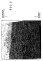
- An intermetallic compound specified by the present invention is shown in Figs. 4 and 5 showing a section of the weld interface surface 6 in the joint of the steel-aluminum welded material.
- Fig. 4 is a typical view of a photograph showing a section of a weld zone in the steel-aluminum welded material shown in Fig. 4 .
- a compound layer of Al 5 Fe 2 is formed on the side of the steel material and a granular or acicular compound layer of Al 3 Fe and Al 19 Fe 4 Si 2 Mn is formed on the side of the aluminum material in the weld interface surface 6.
- a compound layer of Al 5 Fe 2 is formed on the side of the steel material and a granular or acicular compound layer of Al 3 Fe and Al 19 Fe 4 Si 2 Mn is formed on the side of the aluminum material in the weld interface surface 6.
- a vertical dimension l 1 is the mean thickness along the depth of the nugget of a part corresponding to a central part of the nugget of the compound layer of Al 3 Fe and Al 19 Fe 4 Si 2 Mn formed on the side of the aluminum material and a horizontal dimension S 1 is the area of a part of the compound layer of Al 3 Fe and Al 19 Fe 4 Si 2 Mn in this thickness range, namely, the area, in a horizontal plane, of the joint in the steel-aluminum welded material.
- a vertical dimension l 2 is the mean thickness along the depth of the nugget of a part corresponding to the central part of the nugget of the compound layer of Al 5 Fe 2 formed on the side of the steel material and a horizontal dimension S 2 is the area of a part of the compound layer of Al 5 Fe 2 in this thickness range, namely, the area, in a horizontal plane, of the joint in the steel-aluminum welded material.
- the mean thickness l 1 along the depth of the nugget of a part corresponding to the central part of the nugget of the compound layer of Al 3 Fe and Al 19 Fe 9 Si 2 Mn is between 0.5 and 10 ⁇ m to enhance weld strength.
- the term "central part" in the present invention indicates a part within ⁇ 0.1 mm from the center of the nugget.
- the compound of Al 3 Fe and Al 19 Fe 4 Si 2 Mn is an intermetallic compound on the side of the aluminum material. As shown in Fig. 3 and 4 , the compound of Al 3 Fe and Al 19 Fe 4 Si 2 Mn is a granular or acicular compound. Gains of the compound in the central part of the nugget are large (acicular grains of the compound are long) and the grain size of the gains (the length of the acicular grains) decreases gradually toward the periphery of the nugget (toward the right and the left in Figs. 3 and 4 ). The density of the compound grains is small in a peripheral part of the nugget and the compound grains are scattered. the area of the compound layer of Al 3 Fe and Al 19 Fe 4 Si 2 Mn is greater than that of the compound layer of Al 5 Fe 2 .
- the compound of Al 3 Fe and Al 19 Fe 4 Si 2 Mn has an anchoring effect in addition to the effect of the foregoing shape.
- the compound of Al 3 Fe and Al 19 Fe 4 Si 2 Mn improves the adhesion of the compound layer of Al 5 F 2 to the aluminum material and enhances weld strength. Such effects are unavailable when the compound layers of Al 3 Fe and Al 19 Fe 4 Si 2 Mn is excessively thin.
- l 1 is below 0.5 ⁇ m, the anchoring effect is insufficient, the adhesion of the compound layer of Al 5 Fe 2 to the aluminum material is unsatisfactory, interlayer breakage is liable to occur and broken surfaces are flat and smooth.
- the mean thickness l 1 along the depth of the nugget of the part corresponding to the central part of the nugget of the compound layer of Al 3 Fe and Al 19 Fe 4 Si 2 Mn is 0.5 ⁇ m or above.
- the mean thickness l 1 along the depth of the nugget of the part corresponding to the central part of the nugget of the compound layer of Al 3 Fe and Al 19 Fe 4 Si 2 Mn is 10 ⁇ m or below.
- the area S 2 of a part of the compound layer of Al 5 Fe 2 having the mean thickness l 2 in the range between 0.5 and 5 ⁇ m is 10t 2 0.5 mm 2 or above, preferably, 20t 2 0.5 mm 2 or above in addition meeting those conditions on the compound layer on the side of the aluminum material. It is preferable, to enhance weld strength, that the mean thickness l 2 along the depth of the nugget of a part corresponding to the central part of the nugget of the compound layer of Al 5 Fe 2 is in a range between 0.5 and 5 ⁇ m.
- the compound layer of Al 3 Fe and Al 19 Fe 4 Si 2 Mn having the mean thickness l 2 in a range between 0.5 and 10 ⁇ m is formed in a part where the mean thickness l 2 of the compound layer of Al 5 Fe 2 a is formed in the weld interface in the steel-aluminum welded material, the area S 1 of a part of the compound layer of Al 3 Fe and Al 19 Fe 4 Si 2 Mn having a thickness in that thickness range is 15t 2 0.5 mm 2 or above, preferably, 25t 2 0.5 mm 2 or above.
- Weld strength is higher when the area S 1 of a part of the compound layer of Al 3 Fe and Al 19 Fe 4 Si 2 Mn having the mean thickness in that thickness range is larger.
- the area S 1 is below 15t 2 0.5 mm 2 and the strength is the same, it is very likely that the greater the joint area of the nugget, the lower the breaking load (weld strength) sufficient to break the joint.
- the joint area of the nugget is small, the joint is easy to break under a lower load.
- the joint (joint interface) having high weld strength is sufficiently large and hence the breaking load is large. Consequently, the breaking load sufficient to break the joint interface is far greater than that sufficient to break the aluminum material, the interfacial breakage does not occur and the aluminum material breaks.
- the area of the interface reaction layer having the optimum thickness is specified to control the relation between the compound layer on the side of the steel material and that on the side of the aluminum material by the optimum thickness and the optimum area of the interface reaction layer.
- the interface reaction layer is formed intentionally.
- the present invention is based on a technical idea of forming an interface reaction layer of a thickness in an optimum thickness range in a large area; that is, an interface reaction layer is formed in a wide range.
- the joint interface does not break and the joint breaks in the shape of a plug, i.e., a part of the aluminum material on the outer side of the compound layer of Al 3 Fe breaks when the weld strength is high.
- a breakage form of the joint indicates that the joint formed by the present invention has high weld strength.
- the joint interface breaks, the anchoring compound layer of Al 3 Fe and Al 19 Fe 4 Si 2 Mn is torn and the compound layer of Al 5 Fe 2 and the compound layer of Al 3 Fe and Al 19 Fe 4 Si 2 Mn break apart.
- Such a breakage form of the joint indicates that the joint has low weld strength.
- the mean thickness l 1 of the compound layer of Al 3 Fe and Al 19 Fe 4 Si 2 Mn has the highest effect on the enhancement of weld strength.
- the area S 2 of the compound layer of Al 3 Fe having the mean thickness l 2 in the optimum range between 0.5 and 5 ⁇ m has a high effect on the enhancement of weld strength.
- the compound layer of Al 3 Fe and Al 19 Fe 4 Si 2 Mn has the anchoring effect of producing adhesion between the , aluminum material and the compound layer of Al 5 Fe 2 and hence the mean thickness l 1 of the compound layer of Al 3 Fe and Al 19 Fe 4 Si 2 Mn contributes to the enhancement of weld strength in a central part of the nugget. If only the mean thickness l 1 of the compound layer of Al 3 Fe and Al 19 Fe 4 Si 2 Mn is adjusted, it is possible that the interface between the compound layer of Al 3 Fe and Al 19 Fe 4 Si 2 Mn and the compound layer of Al 5 Fe 2 breaks and hence it is possible that breaking load sufficient to break the interface is not very large.
- the area S 2 of the compound layer of Al 5 Fe 2 having the mean thickness l 2 in the optimum thickness range between 0.5 and 5 ⁇ m contributes to ensuring stabilized adhesion in a wide range and has an effect of enhancing breakage load sufficient to break the spot welded joint.
- the strength cannot be stabilized by adjusting only the area S 2 of the compound layer of Al 5 Fe 2 and strength scatters in a wide range. High weld strength can be surely guaranteed by adjusting the area S 2 of the compound layer of Al 5 Fe 2 in addition to adjusting the mean thickness l 1 of the compound layer of Al 3 Fe and Al 19 Fe 4 Si 2 Mn.
- the mean thickness l 2 along the depth of the nugget in a part corresponding to the central part of the nugget of the compound layer of Al 5 Fe 2 and the area S 1 of the compound layer of Al 3 Fe and Al 19 Fe 4 Si 2 Mn having the mean thickness in the optimum thickness range contribute to the enhancement of weld strength.
- the effect of those two factors on the enhancement of weld strength is low.
- those factors are effective in forming a joint having the highest weld strength when those factors are adjusted properly in addition to adjusting the mean thickness l 1 of the compound layer of Al 3 Fe and Al 19 Fe 4 Si 2 Mn and the area S 2 of the compound layer of Al 5 Fe 2 .
- Respective compositions of parts at measuring points 1-1 to 1-24 in the interface of the joint shown in Fig. 5 are measured, and the intermetallic compound is identified by the atomic percents (at.%) of Al, Fe, Si, Mn and Mg contained in those parts.
- Parts having an Al content between 73 and 95 at.%, a Fe content between 5 and 25 at.%, and a Si content below 2 at.% are decided to be those of an Al 3 Fe compound.
- Parts having an Al content between 70 and 78 at. %, a Fe content between 10 and 30 at. %, and a Si content between 2 and 15 at. % are decided to be those of a Al 19 Fe 4 Si 2 Mn compound.
- Parts having an Al content between 60 and 73 at.%, a Fe content between 25 and 30 at.%, and a Si content below 2 at. % are decided to be those of a Al 5 Fe 2 compound.
- the HAADF-STEM method (high angle annular dark field scanning transmission electron microscope method) obtains a signal by connecting electrons scattered by elastic scattering on the side of high angle by an annular detector.
- a HAADF-STEM image is scarcely subject to the influence of diffraction contrast and the contrast is proportional approximately to the square of atomic number (Z).
- An image obtained by the HAAD-STEM method is a two-dimensional map having information about the composition.
- the HAAD-STEM method can accurately detect traces of elements and hence the HAAD-STEM method is effective in analyzing the microstructure of the interface of the joint.
- a welded material is cut across a central part of a nugget to obtain a test sample, the test sample is embedded in a resin such that a section of the test sample can be observed, and the section is mirror-finished by polishing.
- the respective thicknesses of compound layers in an interface reaction layer are measured roughly with a SIM.
- a central part of the nugget, a part on the inner side of the interface of a layer supposed to be a compound layer of Al 5 Fe 2 , parts on the inner and the outer side of the interface of a layer supposed to be a compound layer of Al 3 Fe and Al 19 Fe 4 Si 2 Mn and parts on the inner and the outer side of parts having thicknesses greater than the upper limit thicknesses of the compound layers are thinned in a thickness that permits TEM observation by a FIB process using a focused ion beam machining device (FB-2000A, Hitachi, Ltd.) to obtain a test sample for observation and analysis.
- the test sample was examined with a field emission transmission electron microscope (10,000 ⁇ to 20,000 ⁇ ) (JEM-201F, JEOL). Acceleration voltage is 200 kV and field is 100 ⁇ m.
- Grains and different phases are examined by EDX point analysis to identify a compound layer of Al 5 Fe 2 and a compound layer of Al 3 Fe and Al 19 Fe 4 Si 2 Mn.
- the thickness (length) along depth of the compound layer of Al 3 Fe and Al 19 Fe 4 Si 2 Mn were determined by measuring the thickness of the same in a HAADF-STEM image in a field of 10 ⁇ m. Lengths along depth of granular and acicular grains of Al 3 Fe and Al 19 Fe 4 Si 2 Mn and mean lengths were calculated. Thicknesses (lengths) of five parts of the image of the compound layer of Al 5 Fe 2 were measured and a mean thickness was calculated. All the test samples were measured. When dome-shaped electrode tips were used for spot welding, the respective thicknesses of both the compound layers decreased from a central part toward a peripheral part.
- the diameter of a circle corresponding to a part having a thickness greater than the upper limit and that of a circle corresponding to a part having a thickness below the lower limit of each compound layer were measured, and an area of a part in the optimum thickness range of each compound layer was calculated.
- the interface reaction layer has a desired Mn content and a desired Si content to enhance weld strength.
- the Mn content and the Si content the interface reaction layer are represented by those of a middle part with respect to thickness of the interface reaction layer.
- the middle part of the interface reaction layer has a Mn content 1.5 times that of the steel material or above.
- the middle part of the interface reaction layer has a Si content 1.1 times that of the aluminum material or above and 1.1 times that of the steel material or above.
- the steel material and the aluminum material need to have an optimum Mn content and an optimum Si content and welding conditions for spot welding need to be optimized.
- the Mn content of the interface reaction layer can be increased to 2.5 times that of the steel material at a maximum
- the Si content of the interface reaction layer can be increased up to 1.8 times those of the steel material and the aluminum material at a maximum.
- weld strength is higher when the Mn content and the Si content are higher within the obtained content ranges.
- the Mn content and the Si content of the interface reaction layer can be determined through the determination of the respective secondary ionic strengths of Mn and Si by TEM-EDX analysis or SIMS analysis of the section of the welded joint.
- the SIMS analysis of the secondary ionic strengths of Mn and Si is recommended because errors in data obtained by SIMS analysis are small.
- the ratio of the Mn content of the interface reaction layer to that of the steel material, the ratio of the Si content of the interface reaction layer to that of the steel material and the ration of the Si content of the interface reaction layer to that of the aluminum material are calculated by using data on the secondary ionic strength of Mn and Si in the middle part of the interface reaction layer and data on the Mn contents and Si contents of the aluminum material and the steel material obtained by SIMS.
- the reduction of the thickness of a spot welded part of the aluminum material is limited to the least possible extent to form a joint having sufficient weld strength.
- the smallest thickness ⁇ t of the aluminum material after spot welding is as a standard, 50% of the thickness t 2 or above.
- the smallest thickness ⁇ t is 90% of the thickness t 2 or above.
- the smallest thickness ⁇ t of the aluminum material can be determined by measuring a reduced thickness through the observation of the section with an optical microscope or a SEM and subtracting the measured reduced thickness from the original thickness t 2 of the aluminum material.
- the joining surface of the aluminum material or the steel material may be coated with a deposited film of Zn and/oral having a melting point in a range between 350°C and 950°C before welding together the steel material and the aluminum material.
- the deposited film having a melting point nearly equal to that of the aluminum material and an optimum thickness and interposed between the steel material and the aluminum material can control time in which the interface reaction layer of a steel-aluminum intermetallic compound is formed and can form the interface reaction layer of a proper thickness between 0.5 and 10.5 ⁇ m.
- the deposited film melts and is expelled at the initial stage of welding and cannot suppress the formation of a brittle interface reaction layer. If the deposited film has a thickness above 15 ⁇ m or the deposited film has a melting point above 950°C, a large amount of welding heat input is necessary to melt and expel the deposited film. Therefore, the thickness of the deposited film is in a range between 3 and 15 ⁇ m, preferably, between 5 and 10 ⁇ m and the melting point of the deposited film is in a range between 350°C and 950°C, preferably, 400°C and 900°C. Most preferably, the melting point of the deposited film is in a range between a temperature not lower than the melting point of aluminum and 900°C.
- the thickness of the deposited film is determined by a method including cutting out a test sample from a plated material, embedding the test sample in a resin, polishing the section of the test sample and observing the polished section of the test sample with a SEM.
- the magnification of the SEM is 2,000x and the mean of the measured thicknesses of three points is calculated.
- a deposited film meeting the foregoing conditions is capable of imparting corrosion resistance to the steel material when the deposited film is formed on the steel and of being easily deposited on the steel material and the aluminum material.
- the deposited film is made of a material containing Zn and Al as principal components.
- the deposited film is made of a material containing Zn or Al or containing both Zn and Al in a content of 80% or above.
- the steel material When the steel material is coated beforehand with a deposited film containing Zn and Al as principal components, structural members formed by processing the steel material has an improved corrosion resistance.
- the steel material is coated with a film of a coating material. Even if the film of a coating material is damaged, the steel material, namely, the base material, is protected from corrosion because Zn and Al contained in the deposited film are preferentially corroded. Since the deposited film reduces potential difference between the steel material and the aluminum material, contact corrosion resulting from contact between different metals, which is a problem in the steel-aluminum welded material, can be suppressed.
- Al film, Al-Zn film, Zn film and Zn-Fe film are examples of the deposited film containing Zn or Al as a principal component.
- the deposited film contains Si and Mn.
- the deposited film containing Zn and Al as principal components needs to contain Si and Mn in 5% by mass or above.
- the deposited film contains Si and Mn excessively, a part around the nugget becomes easy to be cracked. This tendency is particularly remarkable when the deposited film contains Mn. Therefore, deposited films containing Zn and Al as principal components and containing Mn and Si other than the Al-Si deposited film are in practicable. In other words, it is significant to increase the Mn content and the Si content of the interface reaction layer by adjusting the Mn content of the steel material and the Si content of the aluminum material.
- a deposited Zn film having a Zn content of 88% by mass or above is recommendable as the deposited film containing Zn and Al as principal components according to the present invention. It is recommended to coat the surface of the steel material with a deposited Zn film having a Fe content in a range betwe4e 8 and 12% by mass.
- a steel material having a surface coated with a deposited Zn film having a Zn content of 88% by mass or above has a particularly high corrosion resistance.
- the melting point of the deposited Zn film can be easily controlled in a range between 350°C and 950°C.
- Iron (Fe) left over after a deposited Zn film having a Zn content of 88% by mass or above and a Fe content in a range between 8 and 12% by mass has been melted and expelled reacts efficiently with the aluminum material. Consequently, the formation of the interface reaction layer can be controlled in a short time and the interface reaction layer can be formed in an optimum thickness in a range between 0.5 and 10.5 ⁇ m.
- corrosion resistance is high and contact corrosion resulting from contact between different metals can be suppressed.
- the deposited film may contain elements in addition to the foregoing elements. Types of the additional elements and the respective contents of the additional elements are to be selectively determined so that the melting point of the deposited film is within the range specified by the present invention, the corrosion resistance of the deposited film may not be deteriorated and faulty welding causing a part around the nugget to crack will not occur.
- the present invention does not place any restrictions on the plating method of plating the steel material or the aluminum material.
- the plating method may be a known wet plating process or a known dry plating process.
- An electroplating process, a hot dipping process, and a plating process including a hot dipping step and a subsequent alloying step are recommended.
- An electroplating process and a zincate conversion process are recommendable for Zn-plating the aluminum material.
- Fig. 3 illustrates a spot welding method of building the steel-aluminum welded material by way of example. Shown in Fig. 3 are a steel material 1, an aluminum alloy sheet 2, a steel-aluminum welded material 3, a nugget 5, and electrodes 7 and 8.
- a comparatively high welding pressure needs to be used for spot welding to form the nugget in a comparatively large necessary area, to form an optimum interface reaction layer in a necessary area and to adjust the mean thickness l 1 of the compound layer of Al 3 Fe and Al 19 Fe 4 Si 2 Mn, the mean thickness l 2 of the part of the compound layer of Al 5 Fe 2 in the central part of the nugget, the area S 1 of the part of the compound layer of Al 3 Fe and Al 19 Fe 4 Si 2 Mn in the optimum thickness range and the area S 2 of the compound layer of Al 5 Fe 2 to those in the corresponding optimum ranges specified by the present invention.
- the welding pressure is within a comparatively high pressure range between 2t 2 0.5 and 4t 2 0.5 kN, where t 2 is the thickness of the aluminum material. Even if the welding pressure is within that pressure range, other welding conditions dominate the formation of the foregoing compound layers and the dimensions of the compound layers are not necessarily within the corresponding optimum ranges specified by the present invention. Therefore, an optimum welding pressure needs to be selected from those in the comparatively high pressure range specified by the present invention according to the qualities of the materials and other welding conditions.
- the area of the nugget decreases with the increase of the welding pressure.
- a welding pressure above 4t 2 0.5 kN is used, a high welding current exceeding the optimum welding current needs to be supplied to form the nugget in a desired area.
- Such a high welding current causes splash and causes the interface reaction layer to grow and hence reduces weld strength.
- the aluminum material deforms greatly and a large depression is formed in a welded part, which affects adversely to the appearance of the steel-aluminum welded material.
- a comparatively high welding current needs to be supplied for a short time for spot welding to form the nugget in a comparatively large necessary area, to form an optimum interface reaction layer in a necessary area and to adjust the mean thickness l 1 of the compound layer of Al 3 Fe and Al 19 Fe 4 Si 2 Mn, the mean thickness l 2 of the part of the compound layer of Al 5 Fe 2 in the central part of the nugget, the area S 1 of the part of the compound layer of Al 3 Fe and Al 19 Fe 4 Si 2 Mn in the optimum thickness range and the area S 2 of the compound layer of Al 5 Fe 2 to those in the corresponding optimum ranges specified by the present invention.
- a comparatively high welding current in a range between 15t 2 0.5 and 30t 2 0.5 kA needs to be supplied for a short time below 100t 2 0.5 ms. Even if the welding current within that current range is supplied for that short time, other welding conditions dominate the formation of the foregoing compound layers and the dimensions of the compound layers are not necessarily within the corresponding optimum ranges specified by the present invention. Therefore, an optimum welding current and an optimum welding time need to be selected from those in the comparatively high current range and those in the time range specified by the present invention according to the qualities of the materials and other welding conditions.
- the welding current is .5 kA or below. Therefore, the welding current is within a range between 15t 2 0.5 and 30t 2 0.5 kA, preferably, 18t 2 0.5 and 30t 2 0.5 kA.
- Welding time is a comparatively shot time of 100t 2 0.5 ms, where t 2 is the thickness of the aluminum material. Although a long welding time exceeding 100t 2 0.5 ms can form the nugget in a desired diameter, such a long welding time causes splash and the growth of the interface reaction layer and, consequently, the weld strength is low.
- the welding time is 100t 2 0.5 ms or below, preferably in a range between 20t 2 0.5 and 80t 2 0.5 ms. It is necessary to select an optimum welding time so that optimum control of the compounds specified by the present invention can be achieved taking into consideration the qualities of materials, welding conditions and the welding current.
- the electrode tips may be of any shape, provided that the nugget of the foregoing area and the interface reaction layer can be formed.
- the electrode tips to be brought into contact respectively with the steel material and the aluminum material may differ from each other in shape and size. Desirably, both the electrode tips to be brought into contact with the steel material and the aluminum material are dome-shaped electrode tips having a rounded end as shown in Fig. 3 .
- the diameter and the radius R of the rounded end of each electrode tip need to be 7 mm or above and 100 mm or above, respectively, to achieve both reducing current density and increasing the area of the nugget.
- it is desirable that the respective polarities of the electrodes to be brought respectively into contact with the aluminum material and the steel material are positive and negative, respectively.
- Both the reduction of current density and the increase of the area of the nugget can be properly achieved by using electrode tips having rounded ends of 7 mm or above in diameter and 120 mm or above in radius.
- a preferable welding pressure is in a range between 2.5t 2 0.5 and 4t 2 0.5 kN
- a preferable welding current is in a range between 18t 2 0.5 and 30t 2 0.5 kA
- a preferable welding time is 100t 2 0.5 ms or below.
- the welding current is increased to form the interface reaction layer in an optimum thickness when the diameter and the radius R of the rounded ends of the electrode tips are increased to reduce current density.
- Welding conditions for lower welding currents may be added to the foregoing welding conditions and welding current may be supplied in a stepped pattern, provided that the additional conditions and the supply of the welding current in the stepped pattern are not detrimental to the formation of the nugget in the desired area and the formation of the interface reaction layer in the optimum thickness.
- Control of the spot welding conditions is important, when the deposited film is formed on the joining surface, to achieve the optimum control of the formation of the interface reaction layer in addition to prevent the deposited film from remaining in the interface reaction layer, to form the nugget in the necessary area and to form the optimum interface reaction layer in the necessary thickness.
- the shape of the electrodes, and the welding pressure have the foregoing actions and effects.
- a selected spot welding process is a high-current spot welding process to form the nugget of the necessary area and the optimum interface reaction layer of the necessary area.
- the high-current spot welding process controls the cracking of the nugget.
- an optimum welding time is dependent on the type and thickness of the deposited film and hence any optimum welding time will not be specified. It is necessary to determine a welding time depending on the diameter of the nugget without depending on the type and the thickness of the deposited film. The foregoing ranges of welding current and the diameter of the nugget are effective.
- the high-current spot welding process cannot completely melt and expel the deposited film and part of the deposited film remains.
- the low-current spot welding process uses a welding pressure in a range between 2t 2 0.5 and 4t 2 0.5 kN and supplies a current in a range between t 2 0.5 and 10t 2 0.5 kA for a time in a range between 100t 2 0.5 and 1000t 2 0.5 ms.
- the welding pressure may be different from that used by the precedent process but must be in the same range.
- a welding current below t 2 0.5 kA or a welding time of 100t 2 0.5 m on melting and expelling the deposited film is insufficient.
- a welding current exceeding 10t 2 0.5 kA or a welding time exceeding 1000t 2 0.5 ms increases the diameter of the nugget, such a welding current or such a welding time promotes the formation of the interface reaction layer and decreases the area of a part of the interface reaction layer having a thickness between 0.5 and 10.5 ⁇ m. Therefore, a plurality of processes including at least two process meeting controlled ranges of conditions.
- the present invention does not place any restrictions on other welding conditions including the waveform of the welding current, the shape and material of the electrodes and voltage. Other welding conditions may be generally practiced ones.
- the welding method of the present invention is applicable to fabricating welded materials regardless of the type of steel materials and aluminum materials.
- Iron-base materials may be, for example, pure iron materials, various steel sheets and plated steel sheets.
- Aluminum materials may be pure aluminum materials and sheets of aluminum alloys of types 2000, 3000, 4000, 5000, 6000 and 7000 specified in International Alloy Standards.
- a test steel having a chemical composition (% by mass) shown in Table 1 was melted.
- a slab of the test steel was rolled to obtain a 1.2 mm thick steel material.
- the steel material was annealed by a continuous annealing process using temperatures between 500°C and 1000°C.
- the annealed steel material was cleaned by water washing or oil washing.
- the cleaned steel material was tempered to obtain a grade 980 MPa high tensile strength steel material.
- Commercially available aluminum alloy sheets respectively of 0.1 mm and 1.6 mm in thickness of A6022 (type 6000) were used as test aluminum materials.
- the steel material and the aluminum alloy sheets were cut into pieces of the shape of a cross tensile test specimen and the pieces of the steel material and the aluminum alloy sheets were welded together by spot welding to obtain steel-aluminum welded materials.
- a dc resistance welding tester was used for spot welding. Welding pressures, welding currents and welding times were determined selectively in connection with the respective thicknesses t 2 of the aluminum materials.
- One point of each of the test specimens was welded under welding conditions shown in Table 2. Dome-shaped electrode tips of a Cu-Cr alloy were used.
- Electrodes tips were 50 mmR-12 mm ⁇ for comparative examples shown in Table 3, 150 mmR-5 mm ⁇ for comparative examples shown in Table 4, 100 mmR-12 mm ⁇ for examples and comparative examples shown in Table 5, 150 mmR-12 mm ⁇ for examples and comparative examples shown in Table6, 120 mmR-7 mm ⁇ for examples and comparative examples shown in Table 7, 120 mmR-12 mm ⁇ for examples and comparative examples shown in table 8.
- the positive electrode was connected to the aluminum material and the negative electrode was connected to the steel material.
- the positive and the negative electrodes were provided with the electrode tips of the same shape.
- a central part of a welded part of each specimen formed by spot welding was cut, the cut specimen was embedded in a resin, the section of the cut specimen was polished and the polished section was observed under an optical microscope.
- the diameter of the nugget in the section was measured and the area of the nugget was calculated. Two perpendicular diameters of the nugget were measured.
- a central part of a welded part of a specimen formed by spot welding was cut, the cut specimen was embedded in a resin, the section of the cut specimen was polished and the polished section was observed with a SEM to measure the thickness of an interface reaction layer.
- a 2000 ⁇ magnification was used when the thickness of the interface reaction layer was 1 ⁇ m or above and a 10000x magnification was used when the thickness of the interface reaction layer was below 1 ⁇ m.
- a part of the interface reaction layer corresponding to a central part of the nugget 5 had the greatest thickness.
- the thickness of the interface reaction layer decreased from the part corresponding to the central part of the nugget 5 toward a peripheral part corresponding to the peripheral part of the nugget 5.
- the diameter of a part of the interface reaction layer having a thickness of 0.5 ⁇ m or above and the diameter of a part of the interface reaction layer having a thickness exceeding 10 ⁇ m were measured and the respective areas of those parts were calculated. Two perpendicular diameters of the nugget were measured.
- the specimens were subjected to a cross tensile strength test to test weld strength.
- the weld strength of the specimen was evaluated in comparison with the weld strength of 1.0 kN of an A6022-A6022 welded material as a reference weld strength.
- the specimens having a weld strength not lower than 1.5 kN or having the aluminum material broken during the cross tensile strength test are marked with a double circle, those having a weld strength between 1.0 and 1.5 kN are marked with a circle, those having a weld strength between 0.5 and 1.0 kN are marked with a triangle and those having a weld strength below 0.5 kN are marked with a cross.
- the cross tensile strength test was used for evaluating strength because results of a tensile shear strength test are greatly dependent on test conditions.
- the characteristic of the results of the tensile shear strength test are similar to that of the results of the cross tensile strength test.
- the specimens respectively having weld strengths determined by the cross tensile strength test and marked with a circle or a double circle had high tensile shear strengths of 2.5 kN or above, respectively.
- Tables 3 to 8 show results of the cross tensile strength test of steel-aluminum welded materials fabricated by welding steel materials shown in Table 1 and A6022 aluminum materials. It is known from the comparison of the dimensions of the electrode tips respectively for the examples and the comparative examples shown in Tables 3 to 8 that the weld strength of the steel-aluminum welded material increases when the diameter and the radius R are increased within the ranges specified by the present invention.
- a test steel having a chemical composition (% by mass) shown in Table 1 was melted.
- a slab of the test steel was rolled to obtain a 1.2 mm thick steel material.
- the steel material was annealed by a continuous annealing process using temperatures between 500°C and 1000°C.
- the annealed steel material was cleaned by water washing or oil washing.
- the cleaned steel material was tempered to obtain a grade 980 MPa high tensile strength steel material.
- Commercially available aluminum alloy sheets respectively of 0.1 mm (Tables 10, 11 and 12) and 1.6 mm (Table 12) in thickness of A6022 (type 6000) were used as test aluminum material.
- the steel sheets (steel materials) and the aluminum alloy sheets (aluminum materials) were cut into pieces of the shape of a cross tensile test specimen specified in A3137, JIS, and the pieces of the steel material and the aluminum alloy sheets were welded together by spot welding under welding conditions shown in Table 9 to obtain steel-aluminum welded materials.
- a dc resistance welding tester was used for spot welding.
- the correlation between welding conditions including welding pressure, welding current and welding time and the control of the mean thickness and area of compounds specified by the present invention was examined beforehand. Welding pressures, welding currents and welding times were determined selectively in connection with the respective thicknesses t 2 of the aluminum materials.
- One point of each of the test specimens was welded under welding conditions shown in Table 9. Dome-shaped electrode tips of a Cu-Cr alloy were used. Dimensions of the electrode tips were 50 mmR-12 mm ⁇ for comparative examples shown in Table 10, 120 mmR-12 mm ⁇ for examples and comparative examples shown in Tables 11 and 12 and 150 mmR-12 mm ⁇ for examples and comparative examples shown in Table 13.
- the positive electrode was connected to the aluminum material and the negative electrode was connected to the steel material.
- the positive and the negative electrodes were provided with the electrode tips of the same shape.
- the respective thicknesses and the areas of parts of interface reaction layers having a thickness in the optimum thickness range of the test specimens were measured by the foregoing measuring methods. Measured data is shown in Tables 10 to 13.
- the specimens were subjected to a cross tensile strength test to test weld strength.
- the weld strength of the specimen was evaluated with reference to the weld strength of 1.0 kN of an A2022-A2022 welded material.
- the specimens having a weld strength above 1.5 kN or having the aluminum material broken during the cross tensile strength test are marked with a double circle, those having a weld strength between 1.0 and 1.5 kN are marked with a circle, those having a weld strength between 0.5 and 1.0 kN are marked with a triangle and those having a weld strength below 0.5 kN are marked with a cross.
- Tables 10 to 13 show results of the cross tensile strength test of steel-aluminum welded materials fabricated by spot welding steel materials shown in Table 1 and A6022 aluminum materials. It is known from Tables 10 to 13 that the steel-aluminum welded materials according to the present invention which has a compound layer of Al 3 Fe and Al 19 Fe 4 Si 2 Mn having a part corresponding to a central part of a nugget and having a means thickness l 1 in a range between 0.5 and 10 ⁇ m have high weld strength.
- the steel-aluminum welded materials according to the present invention formed by controlling the mean thickness l 2 of a part of the compound layer of Al 5 Fe 2 corresponding to the central part of the nugget and the area S 1 of a part of the compound layer of Al 3 Fe and Al 19 Fe 4 Si 2 Mn having a thickness in the optimum thickness range in addition to controlling the mean thickness l 1 of the compound layer of Al 3 Fe and Al 19 Fe 4 Si 2 Mn and the area S 2 of the compound layer of Al 5 Fe 2 have the highest weld strengths as compared with other steel-aluminum welded materials according to the present invention.
- Such welding conditions are indicated at E, F and G in Tables 11 to 13.
- Steel-aluminum welded materials in comparative examples in Tables 10 to 13 not meeting requirements of the present invention have low weld strengths.
- the respective mean thicknesses l 1 of the compound layers of Al 3 Fe and Al 19 Fe 4 Si 2 Mn of the steel-aluminum welded materials in comparative examples shown in Tablets 10 to 13 are outside the optimum thickness range.
- the nuggets of many steel-aluminum welded materials in comparative examples had areas outside the recommended range.
- the nuggets of the steel-aluminum welded materials in comparative examples shown in Table 10 welded by using the 50 mmR-12 mm ⁇ electrode tips had small areas in a range between 12 t 2 0.5 and 19 t 2 0.5 mm 2
- the nuggets of the steel-aluminum welded materials in comparative examples shown in Tables 11 and 12 welded by using the 120 mmR-12 mm ⁇ electrode tips and those shown in Table 13 formed by using the 150 mmR-12 mm ⁇ electrode tips under welding conditions B had small areas in a range between 17 t 2 0.5 and 20 t 2 0.5 mm 2 .
- the nuggets of all the steel-aluminum materials in examples had areas within the above-mentioned recommended range. It is desirable that the areas of nuggets according to the present invention have areas in a range between 20 t 2 0.5 and 70t 2 0.5 mm 2 .
- nuggets of the steel-aluminum welded materials in comparative examples shown in Tables 11 and 12 welded by using the 120 mmR-12 mm ⁇ electrode tips and those shown in Table 13 formed by using the 150 mmR-12 mm ⁇ electrode tips under welding conditions A had areas in a range between 28 t 2 0.5 and 38t 2 0.5 mm 2 and had diameters substantially equal to those of the nuggets of the steel-aluminum materials in examples formed under the welding conditions D, E and G, those steel-aluminum materials in comparative examples has low weld strengths.
- the nugget needs to have an area larger than a certain threshold area as mentioned above, it is more important to control the thickness and structure of the interface reaction layer.
- a test steel having chemical compositions (% by mass) shown in Table 14 was melted.
- a slab of the test steel was rolled to obtain a 1.2 mm thick steel material.
- the steel material was annealed by a continuous annealing process using temperatures between 800°C and 900°C.
- the annealed steel material was cleaned by water washing or oil washing.
- the cleaned steel material was tempered to adjust the strength of the steel material to a desired strength.
- a commercially available 1 mm thick A1050 aluminum alloy sheet containing 0.05% Si and not containing Mn and a commercially available 1 mm thick A6022 aluminum alloy sheet containing 1.10% Si and 0.07% Mn were used as test aluminum materials.
- the steel sheets (steel materials) and the aluminum alloy sheets (aluminum materials) were cut into pieces of the shape of a cross tensile test specimen specified in A3137, JIS, and the pieces of the steel sheets and the aluminum alloy sheets were welded together by spot welding to obtain steel-aluminum welded materials.
- a dc resistance welding tester was used for spot welding. One point of each of the test specimens was welded under welding conditions of G and H shown in Table 9. Dome-shaped 120 mmR-12 mm ⁇ electrode tips of a Cu-Cr alloy were used. The positive electrode was connected to the aluminum material and the negative electrode was connected to the steel material.
- Test specimens for Si and Mn content measurement similar to those for smallest thicknesses measurement were prepared.
- the Si content and the Mn content of each specimen were determined through the measurement of secondary ion intensities by a SIMS (ims5f, CAMECA) .
- Oxygen ions with energy of 8 kV were used as primary ions.
- a small spot of 50 ⁇ m sq. including an interface in a joint was bombarded with a beam of oxygen ions and positive secondary ions sputtered form the specimen were detected for the linear analysis of secondary ions of Mn and Si in a direction perpendicular to the interface of the joint. The measurement was repeated three times.
- the ratios of the Mn secondary ion intensity and the Si secondary ion intensity in a middle part of the interface reaction layer respectively to the Mn secondary ion intensity and the Si secondary ion intensity in the aluminum material and the steel material were determined as a Mn content ratio and a Si content ratio, respectively.
- the mean Mn content ratio and the mean Si content ratio were calculated.
- weld strengths of joints are low when the tensile strength of the steel material is below 400 MPa and that the steel material needs to have a tensile strength of 400 MPa or above desirably, 500 MPa or above, to form joints respectively having high weld strengths. Joints having a high weld strength cannot be formed regardless of spot welding conditions when the steel material has a low C content, a low Mn content, a low Si content and low strength like the mild steel material (SPCE) shown in Tables 15 and 16.
- SPCE mild steel material
- a test steel having a chemical composition having a C content (0.1C-2.3Mn-0.2Cr-0.32Mo)was melted.
- a slab of the test steel was rolled to obtain a 1.2 mm thick steel material.
- the steel material was annealed by a continuous annealing process using temperatures between 500°C and 1000°C.
- the annealed steel material was cleaned by water washing or oil washing.
- the cleaned steel material was tempered to adjust the strength of the steel material to a desired strength of 980 MPa.
- a commercially available 1 mm thick A6022-T4 aluminum alloy sheet having a Si content of 1.01% by mass, a Mn content of 0.07% by mass and a Mg content of 0.6% by mass was used as a test aluminum material.
- the steel material was plated with Zn.
- the steel material was immersed in a 10% sulfuric acid solution for 5 min for acid cleaning and activation.
- the acid-cleaned steel material was plated by different plating processes under the following plating conditions.
- a Zn-electroplating process used a Zn-plating path of pH3 prepared by mixing 400 g/l of zinc sulfate, 30 g/l of aluminum sulfate, 15 g/l of sodium chloride 30 g/l of boric acid and sulfuric acid.
- the steel material was immersed in the plating bath and a current was supplied in 20 A/dm 2 to coat the steel material with a 10 ⁇ m thick Zn film.
- a Zn-10%Ni plating process used a plating bath prepared by adding nickel sulfate and nickel chloride to the plating bath used by the Zn-electroplating process.
- the steel material was immersed in the plating bath and a current was supplied in 10 A/dm 2 to coat the steel material with a 10 ⁇ m thick Zn-10%Ni film.
- a steel material in a comparative example was plated with a 10 ⁇ m thick Ni film by immersing the steel material in a Watts bath and supplying a current in 10 A/dm 2 .
- the steel materials were coated with a 10 ⁇ m thick A1 film, a 10 ⁇ m thick Al-9%Si film, 10 ⁇ m thick Zn-Fe films (Fe contents: 5, 8, 10 and 15%) by hot dipping processes using different types of molten metals.
- the Zn-10%Fe hot dipping process adjusted the Fe content and temperature of the molten metals and pull temperature to form films of 1, 3, 10, 15 and 20 ⁇ m in thickness.
- the aluminum material was plated with Zn. The aluminum material was immersed in a 10% nitric acid solution for 30 s for acid cleaning.
- the acid-cleaned aluminum material was immersed in a plating bath containing 500 g/l of sodium hydrate, 100 g/l of zinc oxide, 1 g/l of ferric chloride and 10 g/l of Rochelle salt for 30 s for zincate conversion. Then, the aluminum material was plated with Zn (containing a Zn alloy) by an electroplating process. A sample of each of the plated material was cut, the cut sample was embedded in a resin and polished and the polished section of the sample was observed under a SEM at a 2000x magnification. Thicknesses of three points on the sample were measured and the mean thickness was calculated.
- the steel sheets (steel materials) and the aluminum alloy sheets (aluminum materials) were cut into pieces of the shape of a cross tensile test specimen specified in A3137, JIS, and the pieces of the steel sheets and the aluminum alloy sheets were welded together by spot welding to obtain a steel-aluminum welded material.
- the spot welding was carried out by three welding processes 1, 2 and 3 using welding currents (kA) and welding times (ms) shown in Table 17.
- the welding processes 2 and 3 are a high-current process and a low-current process, respectively.
- the plating processes 1 to 3 used the same welding pressure.
- Adc resistance welding tester was used. Dome-shaped 120 mmR-12 mm ⁇ electrode tips of a Cu-Cr alloy were used.
- the positive electrode was connected to the aluminum material and the negative electrode was connected to the steel material.
- the aluminum-steel welded material was evaluated in terms of the area of the nugget, the area of a part of the interface reaction layer having a thickness between 0.5 and 10. 5 ⁇ m, weld strength and corrosion resistance. Measured results are shown in Table 18.
- the interface reaction layer is a layer of a compound of Fe and Al having Fe and Al contents of 1% by weight or above and Zn and Ni contents lower than the Fe and Al contents as determined by EDX analysis.
- a layer having Fe and Al contents below 1% by weight and Zn and Ni contents higher than either of the Fe and Al contents was regarded as a deposited layer and was not regarded as an interface reaction layer.
- the respective weld strength of the joints of the steel-aluminum welded material was evaluated by the method mentioned above.
- Results of corrosion resistance tests shown in Table 18 were obtained by subjecting steel-aluminum welded material formed by spot welding to corrosion resistance tests.
- the steel-aluminum welded material was processed by a zinc phosphate coating process and a coating process to simulate the performance of the steel-aluminum welded material as automotive parts or the like.
- Each steel-aluminum welded material was degreased by an alkaline degreasing process, was cleaned by a water washing process and was treated with a solution of 1% Surffine 5N-10 (Nippon Paint Co., Ltd.) for 30s by a surface treatment process.
- the steel-aluminum welded material was immersed for 2 min in a 50°C zinc phosphate bath containing 1.0 g/l zinc ions, 1.0 g/l nickel ions, 0.8 g/l manganese ions, 15.0 g/l phosphoric acid ions, 6.0 g/l nitric acid ions and 0.12 g/l nitrous acid ions and having a toner value of 2.5 pt, a total acidity of 22 pt and an acidity in a range between 0.3 and 0.5 pt for a zinc phosphate treatment.
- the steel-aluminum welded material treated by the zinc phosphate treatment was coated with a cationic electrodeposition coating material (Powertop V50, gray, Nippon Paint Co., Ltd.), and then the coated steel-aluminum welded material was baked at 170°C for 25 min to form a 30 ⁇ m thick coating film.
- a cationic electrodeposition coating material Powertop V50, gray, Nippon Paint Co., Ltd.
- the specimens of the coated steel-aluminum welded material was subjected to a combined corrosion test to evaluate the corrosion resistance of the steel-aluminum welded material.
- the combined corrosion test repeated a test cycle including 2 h of a salt water spray period, 2 h of a drying period and 2 h of a wetting period 100 times.
- the steel and the aluminum material of the thus tested steel-aluminum welded material were separated at the joint and a maximum depth of corrosion in the aluminum material was measured.
- the corrosion resistance of the steel-aluminum welded material was indicated by a circle, a triangle and a cross when the maximum depth of corrosion is below 0.01 mm, between 0.01 and 0.1 mm and 0.1 mm or above, respectively.
- Table 19 shows the effect of plating conditions on weld strength when either of the steel material and the aluminum material was plated by various plating methods. More concretely, Table 19 shows the condition and weld strength of welded parts formed by welding together grade 980 MPa high tensile strength steel material plated respectively by different plating methods and an A6022 aluminum alloy sheet by spot welding under an optimum welding condition I according to the present invention shown in Table 17.
- Each of these steel-aluminum welded materials has a nugget of a comparatively large area, an interface reaction layer of an optimum thickness and a joint having a high weld strength.
- the remaining part of the aluminum material of each of these steel-aluminum welded materials is comparatively thick.
- a thickness reduction of the aluminum material of each of these steel-aluminum welded materials is small, which indicates that splash is suppressed.
- the steel materials or the aluminum materials of the steel-aluminum welded materials in Comparative examples 2, 5, 6, 11, 15 and 16 are coated with deposited films of Ni, Zn and/or A1, respectively.
- the thicknesses and melting points of those deposited films are outside the thickness and the melting point range specified by the present invention.
- nuggets respectively of comparatively large areas are formed in the steel-aluminum welded materials in Comparative examples 2, 5, 6, and 16 provided with the deposited films respectively having excessively high melting points, interface reaction layers are formed scarcely therein even if those steel-aluminum welded materials are formed by spot welding under an optimum condition.
- joints of the steel-aluminum welded materials in those comparative examples have very low weld strengths, respectively, the remaining parts of the aluminum materials have comparatively small minimum thicknesses, respectively, and a thickness reduction of the thickness of the aluminum material of each of these steel-aluminum welded materials is comparatively large.
- the steel-aluminum welded material in Comparative example 15 provided with an excessively thick deposited film has a nugget of a comparatively big diameter, an interface reaction layer is formed scarcely in the same steel-aluminum welded material and hence the joint of this steel-aluminum welded material has a very low weld strength.
- the remaining part of the aluminum material of this steel-aluminum welded material is comparatively thin and the thickness reduction is comparatively large.
- the present invention is capable of forming a steel-aluminum welded material having joints having high weld strength by welding together a steel material and an aluminum material by spot welding in satisfactory repeatability without causing troubles including increase in the reduction of the thickness of the aluminum material.
- the critical significance of the factors including the melting point, the composition and the thickness of the deposited film deposited on the steel material and the aluminum material of the steel-aluminum welded material of the present invention is known from the data shown above.
- Table 18 shows the effect of the spot welding conditions A to I shown in Table 17 on weld strength. More concretely, Table 18 shows the condition and weld strength of welded parts of steel-aluminum welded materials formed by welding together a steel material coated with a 10 ⁇ m thick Zn-10%Fe film by hot dipping, and the foregoing aluminum materials by spot welding under the welding conditions A to I shown in Table 17.
Landscapes
- Engineering & Computer Science (AREA)
- Mechanical Engineering (AREA)
- Resistance Welding (AREA)
Abstract
Description
- The present invention relates to a steel-aluminum welded material formed by welding together a steel material and a steel-aluminum welded material fabricating method according to the preambles of
claims 1 and 11 respectively. - Such a material and such a method are known from "Joining steel and aluminum by resistance spot welding" by W. Beyer, Schweisstechnik (Berlin) November 1970, XP008085538.
- Generally, spot welding is used for welding together members of the same metal. Spot welding will contribute greatly to weight reduction of material, provided that members respectively of different metals, such as an aluminum member and an iron-base member can be welded together by spot welding. The term "aluminum" is used for designating pure aluminum and aluminum alloys, and the term "steel" will be used instead of "iron-base" in this specification.
- A brittle intermetallic compound is likely to be produced in the joint of a steel material and an aluminum material when the steel and the aluminum material are welded together and consequently, it has been very difficult to form a reliable, very strong joint, namely, a joint having high weld strength. Therefore, bolts and rivets have been used for welding together members respectively of different metals. However, joints formed by using bolts or rivets have problems in reliability, air tightness and cost.
- Many studies have been made of spot welding methods of fabricating welded materials each formed by welding together materials respectively of different qualities. Methods that insert an aluminum-steel clad material or a steel pad between a steel material and an aluminum material are proposed in
Patent documents Patent documents patent document 8 sandwiches insulating particles between a steel material and an aluminum material. A method proposed in Patent document 9 forms irregularities in material. A method proposed in Patent document 10 forms nuggets in the interface between a steel plate and an aluminum alloy plate so as to be biased toward the positive pole, namely, the aluminum alloy plate, by the agency of a polarity effect.[Patent document 1] JP-A No. H6-63763 [Patent document 2] JP-A No. H7-178563 [Patent document 3] JP-A No. H4-55066 [Patent document 4] JP-A No. H7-328774 [Patent document 5] JP-A No. H4-251676 [Patent document 6] JP-A No. H7-24581 [Patent document 7] JP-A No. H4-143083 [Patent document 8] JP-A No. H5-228643 [Patent document 9] JP-A No. H9-174249 [Patent document 10] JP-A No. H5-111776 - Those previously proposed methods need an additional process, such as a multilayer spot welding process and a plating process instead of a simple spot welding process. Therefore, additional equipment needs to be added to an existing welding line, which increases welding cost. Those previously proposed methods place restrictions on welding conditions and require difficult work. Many problems, such as the possibility of stably forming joints having high weld strength in satisfactory repeatability and the reduction of weld strength due to the reduction of the thickness of the aluminum material resulting from increases in welding heat input, still reside in those methods.
- Suppression of the cracking of a nugget, as well as the strength of a nugget, is an important requirement for spot welding. None of the previously proposed methods deals with the cracking of a nugget.
- The present invention has been made to solve those problems and it is therefore an object of the present invention to provide a steel-aluminum welded material having high weld strength and capable of being made by spot welding without using any additional materials, such as a clad plate, and without requiring additional processes and to provide a spot welding method for fabricating the steel-aluminum welded material. Another object of the present invention is to provide a steel-aluminum welded material having joints having high weld strength and capable of being stably formed in satisfactory repeatability without causing troubles, such as increase in the reduction of the thickness of the aluminum material, by spot welding and to provide a spot welding method for fabricating the steel-aluminum welded material. A third object of the present invention is to provide a spot welding method that will not cause the cracking of nuggets.
- The inventors of the present invention made studies and acquired the following knowledge and have made the present invention on the basis of the acquired knowledge.
Generally, welding together materials of the same quality, such as steel material or aluminum material, by high weld strength by spot welding can be achieved by promoting the formation of nuggets. It is known that the larger the area of nuggets, the higher both the tensile shear strength and the cross tensile strength of the welded material. The area of a nugget is dependent on heat input; the area of a nugget is larger when heat input is larger or weld time is longer. Therefore, a welded material having high weld strength is obtained, in general, by adjusting the diameter of a nugget through the control of heat input during spot welding. It is important to form a nugget having a proper area because the material is melted to its surface and splash occurs if a nugget having an excessively large area is formed. - When a steel material and an aluminum material are welded together, the amount of heat generated in the steel material is larger than that generated in the aluminum material because the steel material has a melting point and an electrical resistance higher than those of the aluminum material. Consequently, the aluminum material having a low melting point melts first, and then a surface of the steel material melts. Consequently, a brittle Al-Fe intermetallic compound layer is formed between the steel material and the aluminum material. It is known that the intermetallic compound layer formed by spot welding a steel material and an aluminum material consists of two layers; namely, an Al5Fe2 compound layer on the side of the steel material and a compound layer containing, as a principal component, Al3Fe or Al19Fe4Si2Mn on the side of the aluminum material. Those intermetallic compounds are very brittle and hence the steel material and the aluminum material cannot be welded together by high weld strength.
- If the aluminum material melts to its surface and splash occurs, the thickness of the aluminum material decreases and a joint having high weld strength cannot be formed. Whereas a high heat input is needed to form a nugget in a proper diameter to weld together a steel material and an aluminum material, namely, materials respectively of different metals, by a high weld strength by spot welding, it is necessary to suppress the formation of a interface reaction layer in the interface, to limit the melting depth of the steel material to the least extent and to suppress the occurrence of splash to the least extent.
- A nugget of a large area can be formed and the occurrence of splash can be suppressed when a high welding current is supplied for a short time. Such a welding mode can suppress the melting of the steel material in the interface and can reduce the thickness of the interface reaction layer and can enhance weld strength. Although a nugget of a large area can be formed, the reduction of the thickness of the aluminum material increases due to splash if welding is continued for a long time. Moreover, the steel material is melted greatly in the interface, a thick interface reaction layer is formed and hence weld strength is low.
- When a high welding current is used to increase current density, significant splash occurs with a steel material of some steel and a thick interface reaction layer is formed. Although weld strength increases with the increase of welding current, there is a limit to the increase of weld strength. When a nugget having a maximum weld strength is subject to a cross tensile strength test, interfacial fracture occurs at a test force not higher than 1.0 kN/spot and the aluminum material does not break.
- Differing from usual knowledge that a thinner interface reaction layer is desirable, it was found that an interface reaction layer of a thickness in an optimum thickness range is desirable and it is important to form an interface reaction layer of a thickness in the optimum thickness range in a large area. The inventors of the present invention understood that the thickness and structure of an interface reaction layer in the interface between a steel material and an aluminum material need to be adjusted to weld together the steel material and the aluminum material by high weld strength.
- The effect of the thickness of the interface reaction layer on weld strength was studied and it was found that the weld strength is high even if the interface reaction layer consists of a compound layer of Al5Fe2 on the side of the steel material and a compound layer of Al3Fe and Al19Fe4Si2Mn on the side of the aluminum material, provided that the relation between the compound layer of Al5Fe2 and the compound layer of Al3Fe and Al19Fe4Si2Mn in thickness and area meets conditions in an optimum range. The present invention has been made on the basis of such a finding.
- More concretely, it was found that the weld strength can be greatly enhanced when the thickness of the compound layer of Al3Fe and Al19Fe4Si2Mn on the side of the aluminum material relative to the compound layer of Al5Fe2 is adjusted so as to be in an optimum thickness range and the compound layer of Al3Fe and Al19Fe4Si2Mn of a thickness in the optimum thickness range is formed in a large area.
- The inventors of the present invention found that the composition of the interface reaction layer is dependent on the respective qualities of the steel material and the aluminum material and studied the effect of the composition of the interface reaction layer on the weld strength. It was found through studies that Mn and Si contribute to the improvement of the strength of the interface reaction layer. It was found that the Mn content and the Si content of the steel material and the Si content of the aluminum material are closely related with the weld strength and that the strength of an interface reaction layer formed by spot welding increases remarkably when the Mn content and the Si content of the interface reaction layer are adjusted relative to the Mn content and the Si content of the steel material and the Si content of the aluminum material.
- The present invention provides a steel-aluminum welded material formed by welding together a steel material having a thickness t1 in a range between 0.3 and 2.5 mm and an aluminum material having a thickness t2 in a range between 0.5 and 2.5 mm by spot welding, wherein nuggets formed in spot welded parts have an area in a range between 20t2 0.5 and 70t2 0.5 mm2, and a part of each nugget corresponding to a part having a thickness in a range between 0.5 and 10. 5 µm of an interface reaction layer is 10t2 0.5 mm2 or above.
- In the steel-aluminum welded material according to the present invention the interface reaction layer includes a compound layer of Al5Fe2 on the side of the steel material and a compound layer of Al3Fe and Al19Fe4Si2Mn on the side of the aluminum material, and a part of the compound layer of Al3Fe and Al19Fe4Si2Mn corresponding to a central part of the each nugget has a mean thickness along the depth of the nuggets in a range between 0.5 and 10 µm. Preferably, a part of the compound layer of Al5Fe2 having a mean thickness along the depth of the nugget in a range between 0.5 and 5 µm has an area of 10t2 0.5 mm2 or above. Preferably, a part of the compound layer of Al5Fe2 corresponding to a central part of the nugget has a mean thickness along the depth of the nugget in a range between 0.5 and 5 µm. Preferably, a middle part with respect to thickness of the interface reaction layer has a Mn content 1.5 times that of the steel material and a Si content 1.1 times that of the aluminum material and 1.1 times that of the steel material. Preferably, the steel material has a C content in a range between 0.05 and 0.5%, a Mn content in a range between 0.5 and 3% and a Si content in a range between 0.02 and 2.0% and the aluminum material has a Si content in a range between 0.4 and 2%.
- In the steel-aluminum welded material according to the present invention, a joining surface of the steel material or the aluminum material may be coated beforehand by plating with a Zn and/or Al film having a thickness in a range between 3 and 15 µm and a melting point in a range between 350 and 950°C.
- The present invention provides a spot welding method of fabricating a steel-aluminum welded material by welding together a steel material having a thickness t1 in a range between 0.3 and 2.5 mm and an aluminum material having a thickness t2 in a range between 0.5 and 2.5 mm by spot welding using electrode tips each having a rounded end of a diameter of 7 mm or above and a radius R of curvature of 75 mm or above, applying a pressure in a range between 2t2 0.5 and 4t2 0.5 kN to the superposed steel material and the aluminum material with the electrode tips and supplying a welding current in a range between 15t2 0.5 and 30t2 0.5 kA for 100t2 0.5 ms or below. Each of the electrode tips has a rounded end of a diameter of 7 mm or above and a radius R of curvature of 120 mm or above, a pressure in a range between 2.5t2 0.5 and 4t2 0.5 kN is applied to the superposed steel material and the aluminum material with the electrode tips and a welding current in a range between 18t2 0.5 and 30t2 0.5 kA is supplied for a time of 100t2 0.5 ms or below.
- When a joining surface of the steel material or the aluminum material is coated beforehand by plating with a Zn and/or Al film having a thickness in a range between 3 and 15 µm and a melting point in a range between 350°C and 950°C, the spot welding method according to the present invention uses the electrode tips each having a rounded end of a diameter of 7 mm or above and a radius R of curvature of 75 mm or above, and includes a plurality of welding processes including at least two spot welding processes differing from each other in welding current and/or weld time, one of the two spot welding processes is a high-current spot welding process that applies a pressure in a range between 2t2 0.5 and 4t2 0.5 kN to the superposed steel material and the aluminum material with the electrode tips and supplies a welding current in a range between 15t2 0.5 and 30t2 0.5 kA to form a nugget having an area in a range between 20t2 0.5 and 70t2 0.5 nm2 and the other one of the two spot welding processes is a low-current spot welding process, subsequent to the high-current spot welding process, that applies a pressure in a range between 2t2 0.5 and 4t2 0.5 kN to the superposed steel material and the aluminum material with the electrode tips and supplies a welding current in a range between t2 0.5 and 10t2 0.5 kA for a weld time in a range between 100t2 0.5 and 1000t2 0.5 ms.
- According to the present invention, when the steel-aluminum welded material is formed by spot welding, the interface reaction layer of a thickness in the optimum thickness range can be formed in a large area on the side of the aluminum material and nuggets having a large area can be formed. Consequently, the steel-aluminum welded material has a high weld strength. Since the Mn and the Si content of the interface reaction layer are adjusted, the steel-aluminum welded material having a high weld strength can be formed by spot welding without using additional materials and without requiring additional processes.
-
- [
Fig. 1] Fig. 1 is a sectional view of a steel-aluminum welded structure in a first embodiment according to the present invention; - [
Fig. 2] Fig. 2 is a sectional view of a steel-aluminum welded structure in a second embodiment according to the present invention; - [
Fig. 3] Fig. 3 is a view of assistance in explaining a spot welding process for fabricating a steel-aluminum welded material; - [
Fig. 4] Fig. 4 is a typical view of a photograph shown inFig. 5 ; - [
Fig. 5] Fig. 5 is a photograph showing a sectional structure of a weld interface of a welded section in a steel-aluminum welded material according to the present invention. - 1: Steel material, 2: Aluminum alloy sheet, 3: Steel-aluminum welded material, 4: Oxide film, 5: Nugget, 6: Boundary reaction layer, 7 and 8: electrodes and 40: Deposited film
-
Fig. 1 shows a steel-aluminum welded material in a preferred embodiment according to the present invention in a sectional view. As shown inFig. 1 , the steel-aluminum welded structure is formed by welding together asteel material 1, namely, a steel material, and analuminum material 2, namely, an aluminum alloy sheet, by spot welding. Surfaces of thesteel material 1 are coated withoxide films 4, respectively. Anugget 5 has aweld interface surface 6, namely, interface reaction layer, formed by spot welding. A horizontal dimension line inFig. 1 indicates the diameter of thenugget 5. InFig. 1 , t1 indicates the thickness of thesteel material 1, t2 indicates the thickness of thealuminum material 2 and Δt indicates the smallest thickness of a remaining part of the aluminum material after spot welding.Fig. 1 shows a joint having a nugget of a desired diameter formed by suppressing splash. A welded material according to the present invention has a joint as shown inFig. 1 . -
Fig. 2 shows a steel-aluminum welded structure in a second embodiment according to the present invention in a sectional view. A steel-aluminum weldedmaterial 3 shown inFig. 2 is formed by welding together asteel material 1, namely, a steel material, and analuminum material 2, namely, an aluminum alloy sheet, by spot welding. The steel-aluminum weldedmaterial 3 shown inFig. 2 is identical with the steel-aluminum weldedmaterial 3 shown inFig. 1 , except that a joining surface of thesteel material 1 shown inFig. 2 is coated beforehand with a depositedfilm 40. The depositedfilm 40 may be formed at least on the joining surface, namely, one of the surfaces, of either of the steel material and the aluminum material or may be formed on the joining surface and the outer surface, namely, both the surfaces, of either of the steel material and the aluminum material. - Necessary conditions of the present invention and functions thereof will be explained.
- The steel material of the steel-aluminum welded material of the present invention needs to have a thickness t1 in a range between 0.3 and 2.5 mm. Strength and rigidity of a steel material having a thickness t1 below 0.3 mm are insufficient for structural members and structural materials. More over, such an excessively thin steel material is deformed greatly when pressure is applied thereto for spot welding, the oxide film is easily damaged and, therefore, a reaction between the steel material and the aluminum material is promoted. Consequently, an intermetallic compound is likely to be produced. In the case a steel material has a thickness greater than 2.5 mm, a different joining means for forming structural members and structural materials is used, so such a material does not need to be welded to another material by spot welding. Therefore, the thickness t1 of the steel material does not need to be greater than 2.5 mm.
- There are not particular restrictions on the shape and quality of the steel material. The steel material may be of any proper shape and any proper quality, such as a steel material, a steel shape or a steel pipe generally used for forming structural members. Preferably, the steel material has a tensile strength of 400 MPa or above. Generally, most low alloy steels have low strength and most of oxide films are those of oxides of iron. Therefore, Fe and Al diffuse easily and a brittle intermetallic compound is likely to be produced. Thus it is preferable that the steel material has a high tensile strength, desirably, a tensile strength of 400 MPa or above.
- Although the present invention does not place limitative conditions on the composition of the steel material, it is preferable that the steel material meeting the foregoing condition on strength is a high-tension steel material. Steels selectively containing Cr, Mo, V and Ti in addition to C may be used to provide the steel material with high hardenability and precipitation hardenability. Elements Cr, Mo and Nb enhance hardenability and strength, elements V and Ti promote precipitation hardening to enhance strength. However, the toughness of a part around a weld zone decreases and an easily cracking nugget is formed if the steel material contains those alloying elements in an excessively high content. Thus the steel of the steel material has a basic composition having a C content in a range between 0.05 and 0.5% (percent by mass unless otherwise specified), a Mn content in a range between 0.5 and 3.0%, a Si content in a range between 0.02 and 2.0%. Preferably, the steel of the steel material selectively contains, when necessary, one or two or more of elements including Cr, Mo, Nb, V and Ti in a Cr content in a range between 0 to 1%, a Mo content in a range between 0 and 0.2%, a Nb content in a range between 0 and 0.1%, a V content in a range between 0 and 0.1% and a Ti content in a range between 0 and 0.1%. Other elements contained in the steel material are Fe and unavoidable impurities.
- Elements Mn and Si increase the Mn content and Si content of the interface reaction layer to desired content levels, respectively, and increase weld strength. It is conjectured that elements Mn and Si melt during welding, obstruct the diffusion of Fe and Al in the joining surface and suppress the production of a brittle intermetallic compound to the least extent. Elements Mn and Si contained in a high Mn content and a high Si content in the oxide film coating the surface of the steel material enhance the barrier effect of the oxide film to retard contact between molten aluminum melted by spot welding and the steel material.
- Preferably, the Mn content and the Si content of the
oxide film 4 formed on the steel material are twice or above the Mn content and the Si content of the base metal of the steel material, respectively. Although the effects of Mn and Si contained in the oxide film are not elucidated, the oxide film formed on the surface of the steel material has a barrier effect of retarding contact between molten aluminum and the steel material. It is conjectured that the higher the Mn content and the Si content of the oxide film, the higher the barrier effect of the oxide film. It is conjectured that Mn and Si strengthen the oxide film and suppress the breakage of the oxide film by welding pressure. - It is conjectured that, when the oxide film is broken, Mn and Si contained in the oxide film melt, and molten Mn and Si obstruct the diffusion of Fe and Al in the joining surface and suppress the production of a brittle intermetallic compound to the least extent.
- The foregoing effects of Mn and Si are insignificant and the weld strength enhancing effect is not remarkable when the Mn content and the Si content of the oxide film are less than twice the Mn content and the Si content of the steel material, respectively. The Mn content and the Si content of the oxide film are dependent on the Mn content and the Si content, respectively, of the steel material. It is desirable that the steel material has a high Mn content and a high Si content to increase the Mn content and the Si content of the oxide film. However, if the steel material has a high Mn content and a high Si content, the toughness of a part around a weld zone of the steel material is low and an easily cracked nugget is formed. Preferably, the steel material has a Mn content in a range between 1 and 2.5% and a Si content in a range between 0.5 and 1.5%.
- Only the Mn content and the Si content of a surface layer of the steel material having a comparatively low Mn content and a comparatively low Si content may be increased to form an oxide film having a high Mn content and a high Si content. The Mn content and the Si content of the oxide film can be determined through the TEM-EDX analysis of a section of the steel material.
- The thickness of the oxide film having a high Mn content and a high Si content may be in a range between about several tens nanometer and about 1 µm and the oxide film does not need to be excessively thick. An oxide film having a Mn content and a Si content specified by the present invention and having the foregoing thickness has the foregoing barrier effect. The oxide film of such a thickness and having such a composition does not affect welding adversely and can exercise the foregoing barrier effect. Spot welding capable of forming joints having a high weld strength can be achieved without requiring considerable change in conditions on the steel material and a material to be welded to the steel material and the method, by a comparatively simple means for adjusting the composition of the oxide film on the steel material.
- There are not particular restrictions on the alloy and shape of the aluminum material according to the present invention. The aluminum material may be selected from generally used plates, shapes, forged material and cast material so as to meet the requisite properties of structural members. It is desirable that the aluminum material, similarly to the steel material, has high strength to suppress deformation under welding pressure used by spot welding. Optimum aluminum materials are those of the A5000 group and the A6000 group generally used for forming structural members.
- Silicon (Si) contained in the aluminummaterial, similarly to Si contained in the steel material, increases the Si content of the interface reaction layer to a desired level and enhances weld strength. It is conjectured that Si melts during welding and obstructs the diffusion of Fe and Al and suppress the production of a brittle intermetallic compound to the least extent. Therefore, it is preferable that the aluminum material has a Si content in a range between 0.4 and 2%. Preferably, such a desirable aluminum material is selected from those of A6000 group.
- The aluminum material to be used by the present invention has a thickness t2 in a range between 0.5 and 2.5 mm. The strength of structural members made from the aluminum material is insufficient, a nugget having a proper area cannot be formed, the aluminum material melts easily to its surface and splash is liable to occur and hence joints having high weld strength cannot be formed if the thickness t2 of the aluminum material is below 0.5 mm. Since joining means are used for forming structural members and structural materials, an aluminum material of a thickness greater than 2.5 mm does not need to be welded to another material by spot welding. Therefore, the thickness t2 of the aluminum material does not need to be greater than 2.5 mm.
- Preferably, the aluminum material and the steel material are joined together by spot welding such that the area of the
nugget 5 in a spot welded part shown inFig. 1 is in a range between 20t2 0.5 and 70t2 0.5 mm2. In other words, it is necessary to determine spot welding conditions selectively so as to form a nugget having an area in a range between 20t2 0.5 and 70t2 0.5 mm2. - When materials of the same metal having a thickness t are joined together by spot welding, it is a common knowledge that the
nugget 5 having an area on the order of 20t0.5 mm2 is optimum from the viewpoint of strength, operation efficiency and economical effect. The present invention joins together materials of different metals by spot welding that form a nugget of an area larger than that of the optimum nugget to be formed when materials of different metals are joined together. Spot welding is performed so as to form thenugget 5 formed in a spot welded part may have an area in a range between 20t2 0.5 and 70t2 0.5 mm2, where t2 is the thickness of the aluminum material. Such spot welding can form joints having a sufficient weld strength and is excellent in operation efficiency and economical effect. When the materials of different metals are joined together according to the present invention, the optimum diameter of the nugget is dependent on the thickness of the aluminum material and the effect of the thickness of the steel material on the optimum diameter of the nugget is negligibly small. - The area of the nugget below 20t2 0.5 mm2, more strictly, below 30t2 0.5 mm2, is excessively small and weld strength is insufficient. The area of the nugget greater than 70t2 0.5 mm2 provides sufficient weld strength, but splash is liable to occur and the thickness of the aluminum material decreases greatly. Therefore the area of the nugget is in a range between 20t2 0.5 and 70t2 0.5 mm2, preferably, a range between 30t2 0.5 and 70t2 0.5 mm2.
- The area of the nugget formed by the present invention is determined through the measurement of the area of an interface surface in a steel-aluminum joint. A method of measuring the area of an interface surface in a steel-aluminum joint peels or cut off the aluminum material from the interface surface in the steel-aluminum joint and analyzes an image of the aluminum material to determine the area of the nugget. When the nugget has a substantially circular shape, the steel-aluminum joint may be cut, a section of the steel-aluminum joint may be examined with an optical microscope to measure diameters of the nugget in the interface surface and the area of the nugget may be calculated using the measured diameters. Diameters of the nugget in the interface surface along at least two perpendicular directions are measured.
- The area of a part having a thickness in a range between 0. 5 and 10.5 µm of the
interface reaction layer 6 on thenugget 5 shown inFig. 1 is 10t2 0.5 mm2 or above. The area of the interface reaction layer having an optimum thickness is specified in view of weld strength. Contrary to common knowledge that a thinner interface reaction layer is desirable, the present invention forms the interface reaction layer in a thickness in an optimum thickness range. The intention of the present invention is to positively form an interface reaction layer rather than not forming one. The present invention is based on a technical idea of forming an interface reaction layer of a thickness in an optimum thickness range in a large area; that is, an interface reaction layer is formed in a wide range. - A interface reaction layer of a thickness in an optimum thickness range cannot be formed and weld strength is reduced when the area of a part of a thickness in a range between 0.5 and 10 µm of the interface reaction layer is below 10t2 0.5 mm2, more strictly, below 25t2 0.5 mm2. Steel-aluminum diffusion is insufficient and weld strength is low in a part of a thickness below 0.5 µm of the interface reaction layer. A thicker interface reaction layer is more brittle. A part of a thickness greater than 10 µm is particularly brittle and weld strength is low. Thus, the greater the area of the interface reaction layer, the lower the weld strength of the joint. Therefore, the area of a part of a thickness in a range between 0.5 and 10.5 µm of the interface reaction layer needs to be 10t2 0.5 mm2 or above, more strictly, 25t2 0.5 mm2 or above.
- The thickness of the interface reaction layer, similarly to the area of the nugget, is determined through the analysis of an image of a part of the aluminum material in the interface surface in the steel-aluminum joint or the observation of a part of the aluminum material in the interface surface in the steel-aluminum joint with a SEM.
- Preferably, the present invention specifies an intermetallic compound in the steel-aluminum welded material, i.e., in the
weld interface surface 6 shown inFig. 1 . An intermetallic compound specified by the present invention is shown inFigs. 4 and5 showing a section of theweld interface surface 6 in the joint of the steel-aluminum welded material.Fig. 4 is a typical view of a photograph showing a section of a weld zone in the steel-aluminum welded material shown inFig. 4 . - As shown in
Fig. 4 , a compound layer of Al5Fe2 is formed on the side of the steel material and a granular or acicular compound layer of Al3Fe and Al19Fe4Si2Mn is formed on the side of the aluminum material in theweld interface surface 6. InFig. 4 , a vertical dimension l1 is the mean thickness along the depth of the nugget of a part corresponding to a central part of the nugget of the compound layer of Al3Fe and Al19Fe4Si2Mn formed on the side of the aluminum material and a horizontal dimension S1 is the area of a part of the compound layer of Al3Fe and Al19Fe4Si2Mn in this thickness range, namely, the area, in a horizontal plane, of the joint in the steel-aluminum welded material. InFig. 4 , a vertical dimension l2 is the mean thickness along the depth of the nugget of a part corresponding to the central part of the nugget of the compound layer of Al5Fe2 formed on the side of the steel material and a horizontal dimension S2 is the area of a part of the compound layer of Al5Fe2 in this thickness range, namely, the area, in a horizontal plane, of the joint in the steel-aluminum welded material. - Preferably, the mean thickness l1 along the depth of the nugget of a part corresponding to the central part of the nugget of the compound layer of Al3Fe and Al19Fe9Si2Mn is between 0.5 and 10 µm to enhance weld strength. The term "central part" in the present invention indicates a part within ±0.1 mm from the center of the nugget.
- The compound of Al3Fe and Al19Fe4Si2Mn is an intermetallic compound on the side of the aluminum material. As shown in
Fig. 3 and4 , the compound of Al3Fe and Al19Fe4Si2Mn is a granular or acicular compound. Gains of the compound in the central part of the nugget are large (acicular grains of the compound are long) and the grain size of the gains (the length of the acicular grains) decreases gradually toward the periphery of the nugget (toward the right and the left inFigs. 3 and4 ). The density of the compound grains is small in a peripheral part of the nugget and the compound grains are scattered. the area of the compound layer of Al3Fe and Al19Fe4Si2Mn is greater than that of the compound layer of Al5Fe2. - The compound of Al3Fe and Al19Fe4Si2Mn has an anchoring effect in addition to the effect of the foregoing shape. The compound of Al3Fe and Al19Fe4Si2Mn improves the adhesion of the compound layer of Al5F2 to the aluminum material and enhances weld strength. Such effects are unavailable when the compound layers of Al3Fe and Al19Fe4Si2Mn is excessively thin. When l1 is below 0.5 µm, the anchoring effect is insufficient, the adhesion of the compound layer of Al5Fe2 to the aluminum material is unsatisfactory, interlayer breakage is liable to occur and broken surfaces are flat and smooth. According to the present invention, the mean thickness l1 along the depth of the nugget of the part corresponding to the central part of the nugget of the compound layer of Al3Fe and Al19Fe4Si2Mn is 0.5 µm or above.
- If the compound layer of Al3Fe and Al19Fe4Si2Mn grows in an excessively big thickness, fracture starts fro the individual compound grains. When l1 is greater than 10 µm, this tendency is remarkable. According to the present invention, the mean thickness l1 along the depth of the nugget of the part corresponding to the central part of the nugget of the compound layer of Al3Fe and Al19Fe4Si2Mn is 10 µm or below.
- According to the present invention, it is preferable, to enhance weld strength, that the area S2 of a part of the compound layer of Al5Fe2 having the mean thickness l2 in the range between 0.5 and 5 µm is 10t2 0.5 mm2 or above, preferably, 20t2 0.5 mm2 or above in addition meeting those conditions on the compound layer on the side of the aluminum material. It is preferable, to enhance weld strength, that the mean thickness l2 along the depth of the nugget of a part corresponding to the central part of the nugget of the compound layer of Al5Fe2 is in a range between 0.5 and 5 µm.
- It is preferable, to enhance weld strength, to specify the relation between the steel-side compound layer and the aluminum-side compound layer in addition to specifying the conditions respectively for the steel-side compound layer and the aluminum-side compound layer. Preferably, the compound layer of Al3Fe and Al19Fe4Si2Mn having the mean thickness l2 in a range between 0.5 and 10 µm is formed in a part where the mean thickness l2 of the compound layer of Al5Fe2a is formed in the weld interface in the steel-aluminum welded material, the area S1 of a part of the compound layer of Al3Fe and Al19Fe4Si2Mn having a thickness in that thickness range is 15t2 0.5 mm2 or above, preferably, 25t2 0.5 mm2 or above.
- Weld strength is higher when the area S1 of a part of the compound layer of Al3Fe and Al19Fe4Si2Mn having the mean thickness in that thickness range is larger. When the area S1 is below 15t2 0.5 mm2 and the strength is the same, it is very likely that the greater the joint area of the nugget, the lower the breaking load (weld strength) sufficient to break the joint. When the joint area of the nugget is small, the joint is easy to break under a lower load. When the area S1 of a part of the compound layer of Al3Fe and Al19Fe9Si2Mn having a thickness in that thickness range is 25t2 0.5mm2 or above, the joint (joint interface) having high weld strength is sufficiently large and hence the breaking load is large. Consequently, the breaking load sufficient to break the joint interface is far greater than that sufficient to break the aluminum material, the interfacial breakage does not occur and the aluminum material breaks.
- From the viewpoint of weld strength, the area of the interface reaction layer having the optimum thickness is specified to control the relation between the compound layer on the side of the steel material and that on the side of the aluminum material by the optimum thickness and the optimum area of the interface reaction layer. According to the present invention, contrary to common knowledge that a thinner interface reaction layer is desirable, the interface reaction layer is formed intentionally. As mentioned above, the present invention is based on a technical idea of forming an interface reaction layer of a thickness in an optimum thickness range in a large area; that is, an interface reaction layer is formed in a wide range.
- According to the present invention, the joint interface does not break and the joint breaks in the shape of a plug, i.e., a part of the aluminum material on the outer side of the compound layer of Al3Fe breaks when the weld strength is high. In other words, such a breakage form of the joint indicates that the joint formed by the present invention has high weld strength. When the weld strength is low, the joint interface breaks, the anchoring compound layer of Al3Fe and Al19Fe4Si2Mn is torn and the compound layer of Al5Fe2 and the compound layer of Al3Fe and Al19Fe4Si2Mn break apart. Such a breakage form of the joint indicates that the joint has low weld strength.
- The respective effects of factors dominating weld strength will be reviewed.
- The mean thickness l1 of the compound layer of Al3Fe and Al19Fe4Si2Mn has the highest effect on the enhancement of weld strength. The area S2 of the compound layer of Al3Fe having the mean thickness l2 in the optimum range between 0.5 and 5 µm has a high effect on the enhancement of weld strength.
- The compound layer of Al3Fe and Al19Fe4Si2Mn has the anchoring effect of producing adhesion between the , aluminum material and the compound layer of Al5Fe2 and hence the mean thickness l1 of the compound layer of Al3Fe and Al19Fe4Si2Mn contributes to the enhancement of weld strength in a central part of the nugget. If only the mean thickness l1 of the compound layer of Al3Fe and Al19Fe4Si2Mn is adjusted, it is possible that the interface between the compound layer of Al3Fe and Al19Fe4Si2Mn and the compound layer of Al5Fe2 breaks and hence it is possible that breaking load sufficient to break the interface is not very large. The area S2 of the compound layer of Al5Fe2 having the mean thickness l2 in the optimum thickness range between 0.5 and 5 µm contributes to ensuring stabilized adhesion in a wide range and has an effect of enhancing breakage load sufficient to break the spot welded joint. The strength cannot be stabilized by adjusting only the area S2 of the compound layer of Al5Fe2 and strength scatters in a wide range. High weld strength can be surely guaranteed by adjusting the area S2 of the compound layer of Al5Fe2 in addition to adjusting the mean thickness l1 of the compound layer of Al3Fe and Al19Fe4Si2Mn.
- The mean thickness l2 along the depth of the nugget in a part corresponding to the central part of the nugget of the compound layer of Al5Fe2 and the area S1 of the compound layer of Al3Fe and Al19Fe4Si2Mn having the mean thickness in the optimum thickness range contribute to the enhancement of weld strength. However the effect of those two factors on the enhancement of weld strength is low. Although the individual effects of those factors on the enhancement of weld strength is low, those factors are effective in forming a joint having the highest weld strength when those factors are adjusted properly in addition to adjusting the mean thickness l1 of the compound layer of Al3Fe and Al19Fe4Si2Mn and the area S2 of the compound layer of Al5Fe2.
- Method of Measuring Intermetallic Compound A photograph of the structure of the compound layer of Al3Fe and Al19Fe4Si2Mn and the compound layer of Al5Fe2 as shown in
Fig. 5 is obtained through the semiquantitative analysis of an image of a section of the joint obtained by HAADF-STEM (10,000 × to 20,000×) by EDX analysis. In other words, it may be difficult to achieve the recognition of the intermetallic compound specified by the present invention and the accurate measurement of the thickness and area of the intermetallic layer unless the interface of the joint is examined by a HAADF-STEM method, which will be described below. - Respective compositions of parts at measuring points 1-1 to 1-24 in the interface of the joint shown in
Fig. 5 are measured, and the intermetallic compound is identified by the atomic percents (at.%) of Al, Fe, Si, Mn and Mg contained in those parts. Parts having an Al content between 73 and 95 at.%, a Fe content between 5 and 25 at.%, and a Si content below 2 at.% are decided to be those of an Al3Fe compound. Parts having an Al content between 70 and 78 at. %, a Fe content between 10 and 30 at. %, and a Si content between 2 and 15 at. % are decided to be those of a Al19Fe4Si2Mn compound. Parts having an Al content between 60 and 73 at.%, a Fe content between 25 and 30 at.%, and a Si content below 2 at. % are decided to be those of a Al5Fe2 compound. - The HAADF-STEM method (high angle annular dark field scanning transmission electron microscope method) obtains a signal by connecting electrons scattered by elastic scattering on the side of high angle by an annular detector. A HAADF-STEM image is scarcely subject to the influence of diffraction contrast and the contrast is proportional approximately to the square of atomic number (Z). An image obtained by the HAAD-STEM method is a two-dimensional map having information about the composition. The HAAD-STEM method can accurately detect traces of elements and hence the HAAD-STEM method is effective in analyzing the microstructure of the interface of the joint.
- More specifically, a welded material is cut across a central part of a nugget to obtain a test sample, the test sample is embedded in a resin such that a section of the test sample can be observed, and the section is mirror-finished by polishing. The respective thicknesses of compound layers in an interface reaction layer are measured roughly with a SIM. A central part of the nugget, a part on the inner side of the interface of a layer supposed to be a compound layer of Al5Fe2, parts on the inner and the outer side of the interface of a layer supposed to be a compound layer of Al3Fe and Al19Fe4Si2Mn and parts on the inner and the outer side of parts having thicknesses greater than the upper limit thicknesses of the compound layers are thinned in a thickness that permits TEM observation by a FIB process using a focused ion beam machining device (FB-2000A, Hitachi, Ltd.) to obtain a test sample for observation and analysis. The test sample was examined with a field emission transmission electron microscope (10,000× to 20,000×) (JEM-201F, JEOL). Acceleration voltage is 200 kV and field is 100 µm. Grains and different phases are examined by EDX point analysis to identify a compound layer of Al5Fe2 and a compound layer of Al3Fe and Al19Fe4Si2Mn.
- The thickness (length) along depth of the compound layer of Al3Fe and Al19Fe4Si2Mn were determined by measuring the thickness of the same in a HAADF-STEM image in a field of 10 µm. Lengths along depth of granular and acicular grains of Al3Fe and Al19Fe4Si2Mn and mean lengths were calculated. Thicknesses (lengths) of five parts of the image of the compound layer of Al5Fe2 were measured and a mean thickness was calculated. All the test samples were measured. When dome-shaped electrode tips were used for spot welding, the respective thicknesses of both the compound layers decreased from a central part toward a peripheral part. The diameter of a circle corresponding to a part having a thickness greater than the upper limit and that of a circle corresponding to a part having a thickness below the lower limit of each compound layer were measured, and an area of a part in the optimum thickness range of each compound layer was calculated.
- Preferably, the interface reaction layer has a desired Mn content and a desired Si content to enhance weld strength. The Mn content and the Si content the interface reaction layer are represented by those of a middle part with respect to thickness of the interface reaction layer. Preferably, the middle part of the interface reaction layer has a Mn content 1.5 times that of the steel material or above.
- Preferably, the middle part of the interface reaction layer has a Si content 1.1 times that of the aluminum material or above and 1.1 times that of the steel material or above.
- To form an interface reaction layer having the desired Mn content and the desired Si content, the steel material and the aluminum material need to have an optimum Mn content and an optimum Si content and welding conditions for spot welding need to be optimized. Actual tests proved that the Mn content of the interface reaction layer can be increased to 2.5 times that of the steel material at a maximum, and the Si content of the interface reaction layer can be increased up to 1.8 times those of the steel material and the aluminum material at a maximum. There is a tendency that weld strength is higher when the Mn content and the Si content are higher within the obtained content ranges.
- The Mn content and the Si content of the interface reaction layer can be determined through the determination of the respective secondary ionic strengths of Mn and Si by TEM-EDX analysis or SIMS analysis of the section of the welded joint. The SIMS analysis of the secondary ionic strengths of Mn and Si is recommended because errors in data obtained by SIMS analysis are small. The ratio of the Mn content of the interface reaction layer to that of the steel material, the ratio of the Si content of the interface reaction layer to that of the steel material and the ration of the Si content of the interface reaction layer to that of the aluminum material are calculated by using data on the secondary ionic strength of Mn and Si in the middle part of the interface reaction layer and data on the Mn contents and Si contents of the aluminum material and the steel material obtained by SIMS.
- Thickness Reduction of Aluminum Sheet It is desirable that the reduction of the thickness of a spot welded part of the aluminum material is limited to the least possible extent to form a joint having sufficient weld strength. Desirably, the smallest thickness Δt of the aluminum material after spot welding is as a standard, 50% of the thickness t2 or above. Preferably, the smallest thickness Δt is 90% of the thickness t2 or above. The smallest thickness Δt of the aluminum material can be determined by measuring a reduced thickness through the observation of the section with an optical microscope or a SEM and subtracting the measured reduced thickness from the original thickness t2 of the aluminum material.
- The joining surface of the aluminum material or the steel material may be coated with a deposited film of Zn and/oral having a melting point in a range between 350°C and 950°C before welding together the steel material and the aluminum material. The deposited film having a melting point nearly equal to that of the aluminum material and an optimum thickness and interposed between the steel material and the aluminum material can control time in which the interface reaction layer of a steel-aluminum intermetallic compound is formed and can form the interface reaction layer of a proper thickness between 0.5 and 10.5 µm. If the deposited film has a thickness below 3 µm or the deposited film has a melting point below 350°C, the deposited film melts and is expelled at the initial stage of welding and cannot suppress the formation of a brittle interface reaction layer. If the deposited film has a thickness above 15 µm or the deposited film has a melting point above 950°C, a large amount of welding heat input is necessary to melt and expel the deposited film. Therefore, the thickness of the deposited film is in a range between 3 and 15 µm, preferably, between 5 and 10 µm and the melting point of the deposited film is in a range between 350°C and 950°C, preferably, 400°C and 900°C. Most preferably, the melting point of the deposited film is in a range between a temperature not lower than the melting point of aluminum and 900°C.
- The thickness of the deposited film is determined by a method including cutting out a test sample from a plated material, embedding the test sample in a resin, polishing the section of the test sample and observing the polished section of the test sample with a SEM. Preferably, the magnification of the SEM is 2,000x and the mean of the measured thicknesses of three points is calculated.
- A deposited film meeting the foregoing conditions is capable of imparting corrosion resistance to the steel material when the deposited film is formed on the steel and of being easily deposited on the steel material and the aluminum material. Preferably, the deposited film is made of a material containing Zn and Al as principal components. Desirably, the deposited film is made of a material containing Zn or Al or containing both Zn and Al in a content of 80% or above.
- When the steel material is coated beforehand with a deposited film containing Zn and Al as principal components, structural members formed by processing the steel material has an improved corrosion resistance. Generally, the steel material is coated with a film of a coating material. Even if the film of a coating material is damaged, the steel material, namely, the base material, is protected from corrosion because Zn and Al contained in the deposited film are preferentially corroded. Since the deposited film reduces potential difference between the steel material and the aluminum material, contact corrosion resulting from contact between different metals, which is a problem in the steel-aluminum welded material, can be suppressed.
- Al film, Al-Zn film, Zn film and Zn-Fe film are examples of the deposited film containing Zn or Al as a principal component. According to the present invention, it is preferable to suppress the formation of a brittle intermetallic compound layer by increasing the Mn content and the Si content of the interface reaction layer and to form an intermetallic compound layer capable of preventing the interface reaction layer from being easily broken. To achieve such purposes, it seems to be efficient that the deposited film contains Si and Mn. When it is desired to increase the Mn content and the Si content of the interface reaction layer, the deposited film containing Zn and Al as principal components needs to contain Si and Mn in 5% by mass or above. However, if the deposited film contains Si and Mn excessively, a part around the nugget becomes easy to be cracked. This tendency is particularly remarkable when the deposited film contains Mn. Therefore, deposited films containing Zn and Al as principal components and containing Mn and Si other than the Al-Si deposited film are in practicable. In other words, it is significant to increase the Mn content and the Si content of the interface reaction layer by adjusting the Mn content of the steel material and the Si content of the aluminum material.
- It is known from the foregoing description that a deposited Zn film having a Zn content of 88% by mass or above is recommendable as the deposited film containing Zn and Al as principal components according to the present invention. It is recommended to coat the surface of the steel material with a deposited Zn film having a Fe content in a
range betwe4e 8 and 12% by mass. - A steel material having a surface coated with a deposited Zn film having a Zn content of 88% by mass or above has a particularly high corrosion resistance. The melting point of the deposited Zn film can be easily controlled in a range between 350°C and 950°C. Iron (Fe) left over after a deposited Zn film having a Zn content of 88% by mass or above and a Fe content in a range between 8 and 12% by mass has been melted and expelled reacts efficiently with the aluminum material. Consequently, the formation of the interface reaction layer can be controlled in a short time and the interface reaction layer can be formed in an optimum thickness in a range between 0.5 and 10.5 µm. Naturally, corrosion resistance is high and contact corrosion resulting from contact between different metals can be suppressed.
- The deposited film may contain elements in addition to the foregoing elements. Types of the additional elements and the respective contents of the additional elements are to be selectively determined so that the melting point of the deposited film is within the range specified by the present invention, the corrosion resistance of the deposited film may not be deteriorated and faulty welding causing a part around the nugget to crack will not occur.
- The present invention does not place any restrictions on the plating method of plating the steel material or the aluminum material. The plating method may be a known wet plating process or a known dry plating process. An electroplating process, a hot dipping process, and a plating process including a hot dipping step and a subsequent alloying step are recommended. An electroplating process and a zincate conversion process are recommendable for Zn-plating the aluminum material.
-
Fig. 3 illustrates a spot welding method of building the steel-aluminum welded material by way of example. Shown inFig. 3 are asteel material 1, analuminum alloy sheet 2, a steel-aluminum weldedmaterial 3, anugget 5, andelectrodes 7 and 8. - Spot welding conditions for forming a steel-aluminum welded material according to the present invention will be described.
- A comparatively high welding pressure needs to be used for spot welding to form the nugget in a comparatively large necessary area, to form an optimum interface reaction layer in a necessary area and to adjust the mean thickness l1 of the compound layer of Al3Fe and Al19Fe4Si2Mn, the mean thickness l2 of the part of the compound layer of Al5Fe2 in the central part of the nugget, the area S1 of the part of the compound layer of Al3Fe and Al19Fe4Si2Mn in the optimum thickness range and the area S2 of the compound layer of Al5Fe2 to those in the corresponding optimum ranges specified by the present invention.
- More specifically, the welding pressure is within a comparatively high pressure range between 2t2 0.5 and 4t2 0.5 kN, where t2 is the thickness of the aluminum material. Even if the welding pressure is within that pressure range, other welding conditions dominate the formation of the foregoing compound layers and the dimensions of the compound layers are not necessarily within the corresponding optimum ranges specified by the present invention. Therefore, an optimum welding pressure needs to be selected from those in the comparatively high pressure range specified by the present invention according to the qualities of the materials and other welding conditions.
- When a comparatively high welding pressure is used, stable electrical contact between the steel material and the aluminum material and between the electrodes and the materials can be achieved regardless of the shape of the electrode tips, a molten metal in the nugget can be supported by an unmelted part surrounding the nugget. Consequently, the nugget can be formed in a comparatively large necessary area, the interface reaction layer can be formed in a necessary area and expulsion and surface flush can be controlled.
- Spot welding cannot exercise the foregoing effects when a low welding pressures below 2t2 0.5 kN is used. When the welding pressure is excessively low and the electrode tips have rounded ends, the electrode tips are in contact with the steel material and the aluminum material in a small contact area. Consequently, a nugget having a small area is formed, current density increases to cause the interface reaction layer to increase and weld strength decreases. It is highly possible that the compound layer of Al3Fe and Al19Fe4Si2Mn cannot be formed in the mean thickness l1 and the part in the range of ±0.1 mm around the center of the nugget of the compound layer of Al5Fe2 cannot be formed in the mean thickness l2.
- The area of the nugget decreases with the increase of the welding pressure. When a welding pressure above 4t2 0.5 kN is used, a high welding current exceeding the optimum welding current needs to be supplied to form the nugget in a desired area. Such a high welding current causes splash and causes the interface reaction layer to grow and hence reduces weld strength. The aluminum material deforms greatly and a large depression is formed in a welded part, which affects adversely to the appearance of the steel-aluminum welded material.
- A comparatively high welding current needs to be supplied for a short time for spot welding to form the nugget in a comparatively large necessary area, to form an optimum interface reaction layer in a necessary area and to adjust the mean thickness l1 of the compound layer of Al3Fe and Al19Fe4Si2Mn, the mean thickness l2 of the part of the compound layer of Al5Fe2 in the central part of the nugget, the area S1 of the part of the compound layer of Al3Fe and Al19Fe4Si2Mn in the optimum thickness range and the area S2 of the compound layer of Al5Fe2 to those in the corresponding optimum ranges specified by the present invention.
- More specifically, a comparatively high welding current in a range between 15t2 0.5 and 30t2 0.5 kA needs to be supplied for a short time below 100t2 0.5 ms. Even if the welding current within that current range is supplied for that short time, other welding conditions dominate the formation of the foregoing compound layers and the dimensions of the compound layers are not necessarily within the corresponding optimum ranges specified by the present invention. Therefore, an optimum welding current and an optimum welding time need to be selected from those in the comparatively high current range and those in the time range specified by the present invention according to the qualities of the materials and other welding conditions.
- When a comparatively high welding current is supplied for a short time, stable electrical contact between the steel material and the aluminum material, and between the electrodes and the materials can be achieved, a molten metal in the nugget can be supported by an unmelted part surrounding the nugget. Consequently, the nugget can be formed in a comparatively large necessary area, the interface reaction layer can be formed in a necessary area and expulsion and surface flush can be controlled.
- A low welding current below 15t2 0.5kA, more strictly, below 18t2 0.5kA cannot generate a welding heat input sufficient for forming and growing a nugget and, consequently, the nugget cannot be formed in the comparatively large area and the optimum interface reaction layer cannot be formed in the necessary area. It is highly possible that the compound layer of Al3Fe and Al19Fe4Si2Mn cannot be formed in the mean thickness l1 and the part in the range of ±0.1 mm around the center of the nugget of the compound layer of Al5Fe2 cannot be formed in the mean thickness l2.
- To supply a high welding current exceeding 30t2 0.5 kA, additional equipment is needed, which is disadvantageous in work and cost. Thus the welding current is.5 kA or below. Therefore, the welding current is within a range between 15t2 0.5 and 30t2 0.5 kA, preferably, 18t2 0.5 and 30t2 0.5 kA.
- Welding time is a comparatively shot time of 100t2 0.5 ms, where t2 is the thickness of the aluminum material. Although a long welding time exceeding 100t2 0.5 ms can form the nugget in a desired diameter, such a long welding time causes splash and the growth of the interface reaction layer and, consequently, the weld strength is low. To control the interface reaction layer, the welding time is 100t2 0.5 ms or below, preferably in a range between 20t2 0.5 and 80t2 0.5 ms. It is necessary to select an optimum welding time so that optimum control of the compounds specified by the present invention can be achieved taking into consideration the qualities of materials, welding conditions and the welding current.
- The electrode tips may be of any shape, provided that the nugget of the foregoing area and the interface reaction layer can be formed. The electrode tips to be brought into contact respectively with the steel material and the aluminum material may differ from each other in shape and size. Desirably, both the electrode tips to be brought into contact with the steel material and the aluminum material are dome-shaped electrode tips having a rounded end as shown in
Fig. 3 . The diameter and the radius R of the rounded end of each electrode tip need to be 7 mm or above and 100 mm or above, respectively, to achieve both reducing current density and increasing the area of the nugget. When dc spot welding is used, it is desirable that the respective polarities of the electrodes to be brought respectively into contact with the aluminum material and the steel material are positive and negative, respectively. - Both the reduction of current density and the increase of the area of the nugget can be properly achieved by using electrode tips having rounded ends of 7 mm or above in diameter and 120 mm or above in radius. When such electrode tips are used, a preferable welding pressure is in a range between 2.5t2 0.5 and 4t2 0.5 kN, a preferable welding current is in a range between 18t2 0.5 and 30t2 0.5 kA and a preferable welding time is 100t2 0.5 ms or below.
- Those optimum conditions must be well balanced. For example, the welding current is increased to form the interface reaction layer in an optimum thickness when the diameter and the radius R of the rounded ends of the electrode tips are increased to reduce current density. Welding conditions for lower welding currents may be added to the foregoing welding conditions and welding current may be supplied in a stepped pattern, provided that the additional conditions and the supply of the welding current in the stepped pattern are not detrimental to the formation of the nugget in the desired area and the formation of the interface reaction layer in the optimum thickness.
- Description has been made of the welding conditions necessary for forming the nugget of a desired area and the interface reaction layer of the optimum thickness in the steel-aluminum welded material having high weld strength. Description will be made of a spot welding method of welding together a steel material and an aluminum material when a deposited film of Zn and/or Al having a thickness between 3 and 15 µm and a melting point between 350°C and 950°C is formed on the joining surface of the steel material or the aluminum material.
- Control of the spot welding conditions is important, when the deposited film is formed on the joining surface, to achieve the optimum control of the formation of the interface reaction layer in addition to prevent the deposited film from remaining in the interface reaction layer, to form the nugget in the necessary area and to form the optimum interface reaction layer in the necessary thickness.
The shape of the electrodes, and the welding pressure have the foregoing actions and effects. - Preferably, a selected spot welding process is a high-current spot welding process to form the nugget of the necessary area and the optimum interface reaction layer of the necessary area. The high-current spot welding process controls the cracking of the nugget. When there is the deposited film, an optimum welding time is dependent on the type and thickness of the deposited film and hence any optimum welding time will not be specified. It is necessary to determine a welding time depending on the diameter of the nugget without depending on the type and the thickness of the deposited film. The foregoing ranges of welding current and the diameter of the nugget are effective. However, the high-current spot welding process cannot completely melt and expel the deposited film and part of the deposited film remains. Consequently, the area of a part of the interface reaction layer having a thickness between 0.5 and 10.5 µm is small and the area is insufficient to provide high strength. Therefore, a low-current spot welding process subsequent to the high-current spot welding process is necessary to melt and expel the deposited film. The low-current spot welding process uses a welding pressure in a range between 2t2 0.5 and 4t2 0.5 kN and supplies a current in a range between t2 0.5 and 10t2 0.5 kA for a time in a range between 100t2 0.5 and 1000t2 0.5 ms. The welding pressure may be different from that used by the precedent process but must be in the same range. The effect of a welding current below t2 0.5 kA or a welding time of 100t2 0.5 m on melting and expelling the deposited film is insufficient. Whereas a welding current exceeding 10t2 0.5 kA or a welding time exceeding 1000t2 0.5 ms increases the diameter of the nugget, such a welding current or such a welding time promotes the formation of the interface reaction layer and decreases the area of a part of the interface reaction layer having a thickness between 0.5 and 10.5 µm. Therefore, a plurality of processes including at least two process meeting controlled ranges of conditions.
- The present invention does not place any restrictions on other welding conditions including the waveform of the welding current, the shape and material of the electrodes and voltage. Other welding conditions may be generally practiced ones. The welding method of the present invention is applicable to fabricating welded materials regardless of the type of steel materials and aluminum materials. Iron-base materials may be, for example, pure iron materials, various steel sheets and plated steel sheets. Aluminum materials may be pure aluminum materials and sheets of aluminum alloys of types 2000, 3000, 4000, 5000, 6000 and 7000 specified in International Alloy Standards.
- The present invention will be described in terms of examples thereof. The present invention is not limited in its application by the following examples and changes and variations may be made within the scope of the present invention in conformity to the foregoing and the following gist of the present invention.
- A test steel having a chemical composition (% by mass) shown in Table 1 was melted. A slab of the test steel was rolled to obtain a 1.2 mm thick steel material. The steel material was annealed by a continuous annealing process using temperatures between 500°C and 1000°C. The annealed steel material was cleaned by water washing or oil washing. The cleaned steel material was tempered to obtain a grade 980 MPa high tensile strength steel material. Commercially available aluminum alloy sheets respectively of 0.1 mm and 1.6 mm in thickness of A6022 (type 6000) were used as test aluminum materials.
- The steel material and the aluminum alloy sheets were cut into pieces of the shape of a cross tensile test specimen and the pieces of the steel material and the aluminum alloy sheets were welded together by spot welding to obtain steel-aluminum welded materials. A dc resistance welding tester was used for spot welding. Welding pressures, welding currents and welding times were determined selectively in connection with the respective thicknesses t2 of the aluminum materials. One point of each of the test specimens was welded under welding conditions shown in Table 2. Dome-shaped electrode tips of a Cu-Cr alloy were used. Dimensions of the electrode tips were 50 mmR-12 mmφ for comparative examples shown in Table 3, 150 mmR-5 mmφ for comparative examples shown in Table 4, 100 mmR-12 mm φ for examples and comparative examples shown in Table 5, 150 mmR-12 mm φ for examples and comparative examples shown in Table6, 120 mmR-7 mm φ for examples and comparative examples shown in Table 7, 120 mmR-12 mm φ for examples and comparative examples shown in table 8. The positive electrode was connected to the aluminum material and the negative electrode was connected to the steel material. The positive and the negative electrodes were provided with the electrode tips of the same shape.
- A central part of a welded part of each specimen formed by spot welding was cut, the cut specimen was embedded in a resin, the section of the cut specimen was polished and the polished section was observed under an optical microscope. The diameter of the nugget in the section was measured and the area of the nugget was calculated. Two perpendicular diameters of the nugget were measured. A central part of a welded part of a specimen formed by spot welding was cut, the cut specimen was embedded in a resin, the section of the cut specimen was polished and the polished section was observed with a SEM to measure the thickness of an interface reaction layer. A 2000 × magnification was used when the thickness of the interface reaction layer was 1 µm or above and a 10000x magnification was used when the thickness of the interface reaction layer was below 1 µm.
- A part of the interface reaction layer corresponding to a central part of the
nugget 5 had the greatest thickness. The thickness of the interface reaction layer decreased from the part corresponding to the central part of thenugget 5 toward a peripheral part corresponding to the peripheral part of thenugget 5. The diameter of a part of the interface reaction layer having a thickness of 0.5 µm or above and the diameter of a part of the interface reaction layer having a thickness exceeding 10 µm were measured and the respective areas of those parts were calculated. Two perpendicular diameters of the nugget were measured. - The specimens were subjected to a cross tensile strength test to test weld strength. The weld strength of the specimen was evaluated in comparison with the weld strength of 1.0 kN of an A6022-A6022 welded material as a reference weld strength. The specimens having a weld strength not lower than 1.5 kN or having the aluminum material broken during the cross tensile strength test are marked with a double circle, those having a weld strength between 1.0 and 1.5 kN are marked with a circle, those having a weld strength between 0.5 and 1.0 kN are marked with a triangle and those having a weld strength below 0.5 kN are marked with a cross.
- The cross tensile strength test was used for evaluating strength because results of a tensile shear strength test are greatly dependent on test conditions. The characteristic of the results of the tensile shear strength test are similar to that of the results of the cross tensile strength test. The specimens respectively having weld strengths determined by the cross tensile strength test and marked with a circle or a double circle had high tensile shear strengths of 2.5 kN or above, respectively.
- Tables 3 to 8 show results of the cross tensile strength test of steel-aluminum welded materials fabricated by welding steel materials shown in Table 1 and A6022 aluminum materials. It is known from the comparison of the dimensions of the electrode tips respectively for the examples and the comparative examples shown in Tables 3 to 8 that the weld strength of the steel-aluminum welded material increases when the diameter and the radius R are increased within the ranges specified by the present invention. It is known from the comparison of the spot welding conditions shown in Table 2 for the examples and comparative examples shown in Tables 3 to 8 that the area of the nugget and the area of a part of the interface reaction layer having a thickness in the optimum thickness range between 0.5 and 10 µm are large and hence the weld strength is high when the welding pressure, the welding current and the welding time are controlled so as to be within the corresponding ranges specified by the present invention.
TABLE 1 Type Composition (% by mass, Balance: Fe) C Si Mn P S 980 MPa
High tensile
strength steel0.175 1.40 2.00 0.014 0.002 TABLE 2 Mark Spot welding conditions Remarks Welding pressure
(kN)Welding current
(kA)Weld time (ms) A 1.5 20 50 Comparative example B 4.5 20 50 Comparative example C 3 10 50 Comparative example D 3 25 150 Comparative example E 2 15 40 Example F 4 30 20 Example G 3 20 70 Example H 3 25 30 Example TABLE 3 (Comparative example, Electrode tip: 50 mm R, 12 mm Dia.) Spot welding conditions Area of nugget Area
(×t2 0.5mm2Area of interface reaction layer in optimum thickness range
(0.5-1.5 µm)
(×t2 0.5 mm2)Result of cross tensile test Remarks Thickness t2:1.0mm Thickness t2: 1.6 mm Thickness t2: 1.0 mm Thickness t2: 1.6 mm Thickness t2: 1.0 mm Thickness t2: 1.6 mm A 19 0 3 0 Δ × Comparative example B 12 0 2 0 × × Comparative example C 8 0 5 0 × × Comparative example D 18 8 3 0 × × Comparative example E 15 0 5 0 Δ × Comparative example F 19 12 2 2 × × Comparative example G 12 5 5 0 × × Comparative example H 17 7 7 1 × × Comparative example TABLE 4 (Comparative example, Electrode tip: 150 mm R, 5 mm Dia.) Spot welding conditions Area of nugget
(×t2 0.5 mm2)Area of interface reaction layer in optimum thickness range
(0.5-1.5 µm)
(×t2 0.5 mm2)Result of cross tensile test Remarks Thickness t2: 1.0 mm Thickness t2: 1.6 mm Thickness t2: 1.0 mm Thickness t2: 1.6 mm Thickness t2: 1.0 mm Thickness t2: 1.6 mm A 17 15 10 4 Δ × Comparative example B 15 17 12 11 Δ Δ Comparative example C 13 14 2 0 × × Comparative example D 18 13 3 5 × × Comparative example E 19 17 8 10 Δ Δ Comparative example F 18 17 13 11 Δ Δ Comparative example G 19 15 14 13 Δ Δ Comparative example H 17 17 12 11 Δ Δ Comparative example TABLE 5 (Electrode tip: 100 mm R, 12 mm Dia.) Spot welding conditions Area of nugget
(×t2 0.5 mm2)Area of interface reac tion layerin optimum thickness range
(0.5-1.5 µm)
(×T2 0.5 mm2) (×t2 0.5 mm)Result of cross tensile test Remarks Thickness t2: 1.0 mm Thickness t2: 1.6 mm Thickness t2: 1.0 mm Thickness t2: 1.6 mm Thickness t2:1.0 mm Thickness t2: 1.6 mm A 19 18 7 3 Δ × Comparative example B 15 14 4 14 × Δ Comparative example C 10 13 3 5 × × Comparative example D 71 75 4 2 × × Comparative example E 21 24 12 15 ○ ○ Example F 28 29 15 17 ○ ○ Example G 47 59 28 25 ⊚ ⊚ Example H 32 33 25 26 ⊚ ⊚ Example TABLE 6 (Electrode tip: 150 mm R, 12 mm Dia.) Spot welding conditions Area of nugget
(×t2 0.5 mm2)Area of interface reaction layer in optimum thickness range
(0.5-1.5 µm)
(×t2 0.5 mm2)Result of cross tensile test Remarks Thickness t2:1.0mm Thickness t2:1.6mm Thickness t2: 1.0 mm Thickness t2:1.6 mm Thickness t2: 1.0 mm Thickness t2: 1.6 mm A 34 38 11 3 Δ × Comparative example B 18 20 12 15 Δ Δ Comparative example C 14 14 3 2 × × Comparative example D 74 89 6 8 × × Comparative example E 24 27 17 22 O O Example F 38 40 25 28 ⊚ ⊚ Example G 57 64 42 36 ⊚ ⊚ Example H 33 39 30 31 ⊚ ⊚ Example - A test steel having a chemical composition (% by mass) shown in Table 1 was melted. A slab of the test steel was rolled to obtain a 1.2 mm thick steel material. The steel material was annealed by a continuous annealing process using temperatures between 500°C and 1000°C. The annealed steel material was cleaned by water washing or oil washing. The cleaned steel material was tempered to obtain a grade 980 MPa high tensile strength steel material. Commercially available aluminum alloy sheets respectively of 0.1 mm (Tables 10, 11 and 12) and 1.6 mm (Table 12) in thickness of A6022 (type 6000) were used as test aluminum material. The steel sheets (steel materials) and the aluminum alloy sheets (aluminum materials) were cut into pieces of the shape of a cross tensile test specimen specified in A3137, JIS, and the pieces of the steel material and the aluminum alloy sheets were welded together by spot welding under welding conditions shown in Table 9 to obtain steel-aluminum welded materials.
- A dc resistance welding tester was used for spot welding. The correlation between welding conditions including welding pressure, welding current and welding time and the control of the mean thickness and area of compounds specified by the present invention was examined beforehand. Welding pressures, welding currents and welding times were determined selectively in connection with the respective thicknesses t2 of the aluminum materials. One point of each of the test specimens was welded under welding conditions shown in Table 9. Dome-shaped electrode tips of a Cu-Cr alloy were used. Dimensions of the electrode tips were 50 mmR-12 mm φ for comparative examples shown in Table 10, 120 mmR-12 mm φ for examples and comparative examples shown in Tables 11 and 12 and 150 mmR-12 mm φ for examples and comparative examples shown in Table 13. The positive electrode was connected to the aluminum material and the negative electrode was connected to the steel material. The positive and the negative electrodes were provided with the electrode tips of the same shape. The respective thicknesses and the areas of parts of interface reaction layers having a thickness in the optimum thickness range of the test specimens were measured by the foregoing measuring methods. Measured data is shown in Tables 10 to 13.
- The specimens were subjected to a cross tensile strength test to test weld strength. The weld strength of the specimen was evaluated with reference to the weld strength of 1.0 kN of an A2022-A2022 welded material. The specimens having a weld strength above 1.5 kN or having the aluminum material broken during the cross tensile strength test are marked with a double circle, those having a weld strength between 1.0 and 1.5 kN are marked with a circle, those having a weld strength between 0.5 and 1.0 kN are marked with a triangle and those having a weld strength below 0.5 kN are marked with a cross.
- Tables 10 to 13 show results of the cross tensile strength test of steel-aluminum welded materials fabricated by spot welding steel materials shown in Table 1 and A6022 aluminum materials. It is known from Tables 10 to 13 that the steel-aluminum welded materials according to the present invention which has a compound layer of Al3Fe and Al19Fe4Si2Mn having a part corresponding to a central part of a nugget and having a means thickness l1 in a range between 0.5 and 10 µm have high weld strength. The steel-aluminum welded materials according to the present invention formed by controlling the mean thickness l2 of a part of the compound layer of Al5Fe2 corresponding to the central part of the nugget and the area S1 of a part of the compound layer of Al3Fe and Al19Fe4Si2Mn having a thickness in the optimum thickness range in addition to controlling the mean thickness l1 of the compound layer of Al3Fe and Al19Fe4Si2Mn and the area S2 of the compound layer of Al5Fe2 have the highest weld strengths as compared with other steel-aluminum welded materials according to the present invention. Such welding conditions are indicated at E, F and G in Tables 11 to 13. Steel-aluminum welded materials in comparative examples in Tables 10 to 13 not meeting requirements of the present invention have low weld strengths. The respective mean thicknesses l1 of the compound layers of Al3Fe and Al19Fe4Si2Mn of the steel-aluminum welded materials in comparative examples shown in Tablets 10 to 13 are outside the optimum thickness range.
- The nuggets of many steel-aluminum welded materials in comparative examples had areas outside the recommended range. For example, the nuggets of the steel-aluminum welded materials in comparative examples shown in Table 10 welded by using the 50 mmR-12 mm φ electrode tips had small areas in a range between 12 t2 0.5 and 19 t2 0.5 mm2 and the nuggets of the steel-aluminum welded materials in comparative examples shown in Tables 11 and 12 welded by using the 120 mmR-12 mm φ electrode tips and those shown in Table 13 formed by using the 150 mmR-12 mm φ electrode tips under welding conditions B had small areas in a range between 17 t2 0.5 and 20 t2 0.5 mm2. The nuggets of the steel-aluminum welded materials in comparative examples shown in Tables 11 and 12 welded by using the 120 mmR-12 mm φ electrode tips and those shown in Table 13 formed by using the 150 mmR-12 mm φ electrode tips under welding conditions C had large areas in a range between 72 t2 0.5 and 89 t2 0.5 mm2. The nuggets of all the steel-aluminum materials in examples had areas within the above-mentioned recommended range. It is desirable that the areas of nuggets according to the present invention have areas in a range between 20 t2 0.5 and 70t2 0.5 mm2. Although the nuggets of the steel-aluminum welded materials in comparative examples shown in Tables 11 and 12 welded by using the 120 mmR-12 mm φ electrode tips and those shown in Table 13 formed by using the 150 mmR-12 mm φ electrode tips under welding conditions A had areas in a range between 28 t2 0.5 and 38t2 0.5 mm2 and had diameters substantially equal to those of the nuggets of the steel-aluminum materials in examples formed under the welding conditions D, E and G, those steel-aluminum materials in comparative examples has low weld strengths. Although the nugget needs to have an area larger than a certain threshold area as mentioned above, it is more important to control the thickness and structure of the interface reaction layer.
- The aluminum materials of all the steel-aluminum welded materials in examples and comparative examples were similar in thickness reduction and the remaining parts of the aluminum materials had the smallest thicknesses Δt of 50% of the original thicknesses thereof or above.
TABLE 7 (Electrode tip: 120 mm R, 7 mm Dia.) Spot welding conditions Area of nugget
(×t2 0.5 mm2)Area of interface reac tion layer in optimum thickness range
(0.5-1.5 µm)
(×t2 0.5 mm2)Result of cross tensile test Remarks Thickness t2: 1.0 mm Thickness t2: 1.6mm Thickness t2: 1.0 mm Thickness t2: 1.6mm Thickness t2: 1.0 mm Thickness t2: 1.6 mm A 20 23 10 5 Δ × Comparative example B 15 19 10 10 Δ Δ Comparative example C 14 15 2 3 × × Comparative example D 35 39 6 8 × × Comparative example E 21 24 14 20 O O Example F 32 37 26 28 ⊚ ⊚ Example G 37 38 26 29 ⊚ ⊚ Example H 32 35 26 27 ⊚ ⊚ Example TABLE 8 (Electrode tip: 120 mm R, 12 mm Dia.) Spot welding conditions Area of nugget
(×t2 0.5mm2)Area of interface reaction layer in optimum thickness range
(0.5-1.5 µm)
(×t2 0.5mm2)Result of cross tensile test Remarks Thickness t2:1.0mm Thickness t2: 1.6 mm Thickness t2:1.0mm Thickness t2: 1.6 mm Thickness t2: 1.0 mm Thickness t2: 1.6 mm A 28 30 10 3 Δ × Comparative example B 17 18 10 15 Δ Δ Comparative example C 13 14 4 3 × × Comparative example D 72 85 5 6 × × Comparative example E 23 25 15 20 ○ ○ Example F 35 36 23 25 ⊚ ⊚ Example G 54 63 40 33 ⊚ ⊚ Example H 33 40 29 32 ⊚ ⊚ Example TABLE 9 Mark Spot welding conditions Welding pressure
(kN)Welding current
(kA)Weld time (ms) A 1.5 20 50 B 3 10 50 C 3 25 150 D 2 15 40 E 4 30 20 F 3 20 70 G 3 25 30 TABLE 10 (Electrode tip: 50 mm R, 12 mm Dia., Thickness t2: 1.0 mm) Spot welding conditions Al3Fe + Al19Fe4Si2Mn compound layer Al5Fe2 compound layer Results of cross tensile test Remarks Central mean thickness
l1 (µm)Area S1 of part in optimum thickness range
(×t2 0.5mm2)Central mean thickness
l2 (µm)Area S2 of part in optimum thickness range
(×t2 0.5 mm2)A 11.5 3 4.9 3 Δ Comparative example B - - - - × Comparative example C 22.4 3 7.3 2 × Comparative example D 0.4 0 0.5 < 1 Δ Comparative example E 15.3 2 6.5 2 × Comparative example F 14.2 8 3.7 6 × Comparative example G 10.2 10 4.9 8 × Comparative example Note: Cross (×) indicates unwelded state TABLE 11 (Electrode tip: 120 mm R, 12 mm Dia., Thickness t2: 1.0 mm) Spot welding conditions Al3Fe + Al19Fe4Si2Mn compound layer Al5Fe2 compound layer Results of cross tensile test Remarks Central mean thickness
l1 (µm)Area S1 of part in optimum thickness range
(×t2 0.5 mm2)Central mean thickness
l2 (µm)Area S2 of part in optimum thickness range
(×t2 0.5 mm2)A 10.7 10 3.1 5 
Comparative example B 0.4 0 0.6 2 × Comparative example C 13.3 5 3.6 4 × Comparative example D 3.3 15 0.8 12 o Example E 9.8 31 4.9 23 
Example F 7.4 27 3.7 24 
Example G 8.3 25 3.5 20 
Example - A test steel having chemical compositions (% by mass) shown in Table 14 was melted. A slab of the test steel was rolled to obtain a 1.2 mm thick steel material. The steel material was annealed by a continuous annealing process using temperatures between 800°C and 900°C. The annealed steel material was cleaned by water washing or oil washing. The cleaned steel material was tempered to adjust the strength of the steel material to a desired strength. A commercially available 1 mm thick A1050 aluminum alloy sheet containing 0.05% Si and not containing Mn and a commercially available 1 mm thick A6022 aluminum alloy sheet containing 1.10% Si and 0.07% Mn were used as test aluminum materials. The steel sheets (steel materials) and the aluminum alloy sheets (aluminum materials) were cut into pieces of the shape of a cross tensile test specimen specified in A3137, JIS, and the pieces of the steel sheets and the aluminum alloy sheets were welded together by spot welding to obtain steel-aluminum welded materials.
- A dc resistance welding tester was used for spot welding. One point of each of the test specimens was welded under welding conditions of G and H shown in Table 9. Dome-shaped 120 mmR-12 mm φ electrode tips of a Cu-Cr alloy were used. The positive electrode was connected to the aluminum material and the negative electrode was connected to the steel material.
- Parts of the aluminum materials of the specimens remained after spot welding had smallest thicknesses Δt of 50% of the original thicknesses thereof or above. A central part of a welded part of each specimen formed by spot welding was cut, the cut specimen was embedded in a resin, the section of the cut specimen was polished and the polished section was observed under an optical microscope to determine the smallest thickness Δt.
- Test specimens for Si and Mn content measurement similar to those for smallest thicknesses measurement were prepared. The Si content and the Mn content of each specimen were determined through the measurement of secondary ion intensities by a SIMS (ims5f, CAMECA) . Oxygen ions with energy of 8 kV were used as primary ions. A small spot of 50 µm sq. including an interface in a joint was bombarded with a beam of oxygen ions and positive secondary ions sputtered form the specimen were detected for the linear analysis of secondary ions of Mn and Si in a direction perpendicular to the interface of the joint. The measurement was repeated three times. The ratios of the Mn secondary ion intensity and the Si secondary ion intensity in a middle part of the interface reaction layer respectively to the Mn secondary ion intensity and the Si secondary ion intensity in the aluminum material and the steel material were determined as a Mn content ratio and a Si content ratio, respectively. The mean Mn content ratio and the mean Si content ratio were calculated.
- Results of the cross tensile strength test of steel-aluminum welded materials obtained by spot welding steel materials shown in Table 14 and the above-mentioned aluminum materials are shown in Tables 15 and 16.
- It is obvious from Tables 15 and 16 that weld strengths of joints are low when the tensile strength of the steel material is below 400 MPa and that the steel material needs to have a tensile strength of 400 MPa or above desirably, 500 MPa or above, to form joints respectively having high weld strengths. Joints having a high weld strength cannot be formed regardless of spot welding conditions when the steel material has a low C content, a low Mn content, a low Si content and low strength like the mild steel material (SPCE) shown in Tables 15 and 16.
- It is known from Tables 15 and 16 that even if the steel material has a sufficiently high tensile strength or even if the steel material has the foregoing desired composition, the weld strength is low when the area of a part of the interface reaction layer of a thickness between 0.5 and 10.5 µm is outside the desired area range specified by the present invention. It is known from Tables 15 and 16 also that a joint having a high weld strength can be formed when the nugget has a diameter in the desired range, a part of the interface reaction layer of a thickness between 0.5 and 10. 5 µm is within the desired area range and the interface reaction layer has a high Mn content ratio and a high Si content ratio.
- When the aluminum material has a low Si content like the A1050 aluminum alloy sheet shown in Tables 15 and 16, the weld strength of a joint cannot be increased beyond a certain limit regardless of the spot welding conditions.
TABLE 12 (Electrode tip: 120 mm R, 12 mm Dia., Thickness t2: 1.6 mm) Spot welding conditions Al3Fe + Al19Fe4Si2Mn compound layer Al5Fe2 compound layer Results of cross tensile test Remarks Central mean thickness
l1 (µm)Area S1 of part in optimum thickness range
(×t2 0.5 mm2)Central mean thickness
l2 (µm)Area S2 of part in optimum thickness range
(×t2 0.5 mm2)A 10.1 3 1.4 2 Δ Comparative example B - - - - × Comparative example C 11.9 5 1.2 3 × Comparative example D 1.4 9 0.6 8 ○ Example E 8.8 23 4.5 18 ⊚ Example F 5.9 28 2.8 21 ⊚ Example G 6.1 27 2.9 24 ⊚ Example TABLE 13 (Electrode tip: 150 mm R, 12 mm Dia., Thickness t2: 1.0 mm) Spot welding conditions Al3Fe + Al19Fe4Si2Mn compound layer Al5Fe2 compound layer Results of cross tensile test Remarks Central mean thickness
l1 (µm)Area S1 of part in optimum thickness range
(×t2 0.5 mm2)Central mean thickness
l2 (µm)Area S2 of part in optimum thickness range
(×t2 0.5 mm2)A 10.5 11 2.9 8 Δ Comparative example B 0.4 < 1 0.3 1 × Comparative example C 11.8 8 3.0 4 × Comparative example D 1.8 18 0.7 14 ○ Example E 8.0 27 4.1 25 ⊚ Example F 6.9 44 3.2 29 ⊚ Example G 6.8 35 2.9 30 ⊚ Example TABLE 14 C Si Mn P S Remarks SPCE 0.01 0.02 0.15 0.011 0.006 Comparative example 440 MPa
High tensile strength steel0.14 0.03 0.91 0.01 0.003 590 MPa
High tensile strength steel0.057 0.51 1.18 0.008 0.003 980 MPa
High tensile strength steel0.175 1.38 1.98 0.014 0.002 - A test steel having a chemical composition having a C content (0.1C-2.3Mn-0.2Cr-0.32Mo)was melted. A slab of the test steel was rolled to obtain a 1.2 mm thick steel material. The steel material was annealed by a continuous annealing process using temperatures between 500°C and 1000°C. The annealed steel material was cleaned by water washing or oil washing. The cleaned steel material was tempered to adjust the strength of the steel material to a desired strength of 980 MPa. A commercially available 1 mm thick A6022-T4 aluminum alloy sheet having a Si content of 1.01% by mass, a Mn content of 0.07% by mass and a Mg content of 0.6% by mass was used as a test aluminum material.
- The steel material was plated with Zn. The steel material was immersed in a 10% sulfuric acid solution for 5 min for acid cleaning and activation. The acid-cleaned steel material was plated by different plating processes under the following plating conditions. A Zn-electroplating process used a Zn-plating path of pH3 prepared by mixing 400 g/l of zinc sulfate, 30 g/l of aluminum sulfate, 15 g/l of sodium chloride 30 g/l of boric acid and sulfuric acid. The steel material was immersed in the plating bath and a current was supplied in 20 A/dm2 to coat the steel material with a 10 µm thick Zn film. A Zn-10%Ni plating process used a plating bath prepared by adding nickel sulfate and nickel chloride to the plating bath used by the Zn-electroplating process. The steel material was immersed in the plating bath and a current was supplied in 10 A/dm2 to coat the steel material with a 10 µm thick Zn-10%Ni film. A steel material in a comparative example was plated with a 10 µm thick Ni film by immersing the steel material in a Watts bath and supplying a current in 10 A/dm2.
- The steel materials were coated with a 10 µm thick A1 film, a 10 µm thick Al-9%Si film, 10 µm thick Zn-Fe films (Fe contents: 5, 8, 10 and 15%) by hot dipping processes using different types of molten metals. The Zn-10%Fe hot dipping process adjusted the Fe content and temperature of the molten metals and pull temperature to form films of 1, 3, 10, 15 and 20 µm in thickness. The aluminum material was plated with Zn. The aluminum material was immersed in a 10% nitric acid solution for 30 s for acid cleaning. The acid-cleaned aluminum material was immersed in a plating bath containing 500 g/l of sodium hydrate, 100 g/l of zinc oxide, 1 g/l of ferric chloride and 10 g/l of Rochelle salt for 30 s for zincate conversion. Then, the aluminum material was plated with Zn (containing a Zn alloy) by an electroplating process. A sample of each of the plated material was cut, the cut sample was embedded in a resin and polished and the polished section of the sample was observed under a SEM at a 2000x magnification. Thicknesses of three points on the sample were measured and the mean thickness was calculated. The steel sheets (steel materials) and the aluminum alloy sheets (aluminum materials) were cut into pieces of the shape of a cross tensile test specimen specified in A3137, JIS, and the pieces of the steel sheets and the aluminum alloy sheets were welded together by spot welding to obtain a steel-aluminum welded material.
- The spot welding was carried out by three
welding processes - The weld strength was measured by the measuring method mentioned above. The interface reaction layer is a layer of a compound of Fe and Al having Fe and Al contents of 1% by weight or above and Zn and Ni contents lower than the Fe and Al contents as determined by EDX analysis. A layer having Fe and Al contents below 1% by weight and Zn and Ni contents higher than either of the Fe and Al contents was regarded as a deposited layer and was not regarded as an interface reaction layer.
- The respective weld strength of the joints of the steel-aluminum welded material was evaluated by the method mentioned above.
Results of corrosion resistance tests shown in Table 18 were obtained by subjecting steel-aluminum welded material formed by spot welding to corrosion resistance tests. The steel-aluminum welded material was processed by a zinc phosphate coating process and a coating process to simulate the performance of the steel-aluminum welded material as automotive parts or the like. Each steel-aluminum welded material was degreased by an alkaline degreasing process, was cleaned by a water washing process and was treated with a solution of 1% Surffine 5N-10 (Nippon Paint Co., Ltd.) for 30s by a surface treatment process. Then, the steel-aluminum welded material was immersed for 2 min in a 50°C zinc phosphate bath containing 1.0 g/l zinc ions, 1.0 g/l nickel ions, 0.8 g/l manganese ions, 15.0 g/l phosphoric acid ions, 6.0 g/l nitric acid ions and 0.12 g/l nitrous acid ions and having a toner value of 2.5 pt, a total acidity of 22 pt and an acidity in a range between 0.3 and 0.5 pt for a zinc phosphate treatment. The steel-aluminum welded material treated by the zinc phosphate treatment was coated with a cationic electrodeposition coating material (Powertop V50, gray, Nippon Paint Co., Ltd.), and then the coated steel-aluminum welded material was baked at 170°C for 25 min to form a 30 µm thick coating film. - The specimens of the coated steel-aluminum welded material was subjected to a combined corrosion test to evaluate the corrosion resistance of the steel-aluminum welded material. The combined corrosion test repeated a test cycle including 2 h of a salt water spray period, 2 h of a drying period and 2 h of a wetting period 100 times. The steel and the aluminum material of the thus tested steel-aluminum welded material were separated at the joint and a maximum depth of corrosion in the aluminum material was measured. The corrosion resistance of the steel-aluminum welded material was indicated by a circle, a triangle and a cross when the maximum depth of corrosion is below 0.01 mm, between 0.01 and 0.1 mm and 0.1 mm or above, respectively.
- Table 19 shows the effect of plating conditions on weld strength when either of the steel material and the aluminum material was plated by various plating methods. More concretely, Table 19 shows the condition and weld strength of welded parts formed by welding together grade 980 MPa high tensile strength steel material plated respectively by different plating methods and an A6022 aluminum alloy sheet by spot welding under an optimum welding condition I according to the present invention shown in Table 17.
- It is known from data on the steel-aluminum welded material in Comparative example 1 shown in Table 19 that a steel-aluminum welded material has a low weld strength determined by a cross tensile strength test and is unsatisfactory in corrosion resistance even if the steel material and the aluminum material are welded under the optimum welding condition unless either of the steel material and the aluminum material is plated. The steel materials or the aluminum materials of the steel-aluminum welded materials in Examples 3, 4, 7 to 10 and 12 to 14 of the present invention are coated respectively with deposited films of Zn and/or A1 having a thickness between 3 and 15 µm and a melting point between 350°C and 950°C before spot welding. Each of these steel-aluminum welded materials has a nugget of a comparatively large area, an interface reaction layer of an optimum thickness and a joint having a high weld strength. The remaining part of the aluminum material of each of these steel-aluminum welded materials is comparatively thick. A thickness reduction of the aluminum material of each of these steel-aluminum welded materials is small, which indicates that splash is suppressed.
- The steel materials or the aluminum materials of the steel-aluminum welded materials in Comparative examples 2, 5, 6, 11, 15 and 16 are coated with deposited films of Ni, Zn and/or A1, respectively. However, the thicknesses and melting points of those deposited films are outside the thickness and the melting point range specified by the present invention. Although nuggets respectively of comparatively large areas are formed in the steel-aluminum welded materials in Comparative examples 2, 5, 6, and 16 provided with the deposited films respectively having excessively high melting points, interface reaction layers are formed scarcely therein even if those steel-aluminum welded materials are formed by spot welding under an optimum condition. Consequently, joints of the steel-aluminum welded materials in those comparative examples have very low weld strengths, respectively, the remaining parts of the aluminum materials have comparatively small minimum thicknesses, respectively, and a thickness reduction of the thickness of the aluminum material of each of these steel-aluminum welded materials is comparatively large.
- The steel-aluminum welded material in Comparative example 11 formed by spot welding under the optimum condition and provided with an excessively thin deposited film, similarly to the steel-aluminum welded material in Comparative example 1, is unsatisfactory in weld strength and in corrosion resistance. Although the steel-aluminum welded material in Comparative example 15 provided with an excessively thick deposited film has a nugget of a comparatively big diameter, an interface reaction layer is formed scarcely in the same steel-aluminum welded material and hence the joint of this steel-aluminum welded material has a very low weld strength. The remaining part of the aluminum material of this steel-aluminum welded material is comparatively thin and the thickness reduction is comparatively large.
- As obvious from the data shown above, the present invention is capable of forming a steel-aluminum welded material having joints having high weld strength by welding together a steel material and an aluminum material by spot welding in satisfactory repeatability without causing troubles including increase in the reduction of the thickness of the aluminum material. The critical significance of the factors including the melting point, the composition and the thickness of the deposited film deposited on the steel material and the aluminum material of the steel-aluminum welded material of the present invention is known from the data shown above.
- Table 18 shows the effect of the spot welding conditions A to I shown in Table 17 on weld strength. More concretely, Table 18 shows the condition and weld strength of welded parts of steel-aluminum welded materials formed by welding together a steel material coated with a 10 µm thick Zn-10%Fe film by hot dipping, and the foregoing aluminum materials by spot welding under the welding conditions A to I shown in Table 17.
- It is known from Table 18 that joints having a high weld strength can be formed by spot welding under the optimum welding conditions H and I each including a high current mode and a low current mode.
TABLE 15 Welding condition G Type of steel Type of aluminum Area of nugget
(mm2)Area of interface reaction layer in optimum thickness range
(0.5-1.5 µm)
(mm2)Mn and Si contents of interface reaction layer Result of cross tensile test Remarks Mn content ratio with steel Si content ratio Steel Aluminum SPCE 6022 48 9 1.6 30.0 0.6 × Comparative example 590 MPa 1050 51 21 0.8 0.9 9.0 ○ Example 440 MPa 6022 50 27 1.5 43.3 1.3 ⊚ Example 980 MPa 6022 54 40 1.5 1.4 1.9 ⊚ Example TABLE 16 Welding condition H Type of steel Type of aluminum Area of nugget
(mm2)Area of interface reaction layer in optimum thickness range
(0.5-1.5µm)
(mm2)Mn and Si Contents of interface reaction layer Result of cross tensile test Remarks Mn Content ratio with steel Si Content ratio Steel Aluminum SPCE 6022 30 7 1.9 40.0 0.8 × Comparative example 590 MPa 1050 34 10 2.2 1.3 13.0 ⊚ Example 440 MPa 6022 31 16 1.6 36.7 1.1 ⊚ Example 980 MPa 6022 33 29 2.0 1.7 2.4 ⊚ Example TABLE 17 Welding process 1Welding process 2 (High current mode) Welding process 3 (Low current mode) Welding pressure (kN) Remarks A 6kA-200msec 20kA-200msec 8kA-500msec 1.5 Comparative example B 12kA-500msec 6kA- 500msec 3 Comparative example C 40kA-150msec 3kA- 500msec 3 Comparative example D 25kA-200msec 0.5kA- 400msec 2 Comparativeexample E 6kA-200msec 25kA-200msec 15kA- 700msec 4 Comparative example F 25kA-200msec 6kA- 80msec 2 Comparative example G 25kA-200msec 8kA- 2000msec 4 Comparative example H 6kA-200msec 25kA-200msec 1 kA-1000msec 3 I 25kA-200msec 8kA- 400msec 3 TABLE 18 Area of nugget
(mm2)Area of optimum interface reaction layer
(mm2)Result of cross tensile test Remarks A 41 3 × Comparative example B 18 2 × Comparative example C 79 15 × Comparative example D 40 6 Δ Comparative example E 74 12 Δ Comparative example F 62 8 Δ Comparative example G 36 5 Δ Comparative example H 40 30 ○ Example I 42 36 ⊚ Example TABLE 19 Quality of plated film Plating method Base material Thickness (µm) Melting point (°C) Area of nugget (mm2) Area of optimum interface reaction layer (mm2) Result of cross tensile test Result of corrosion test Remarks 1 Not plated - - - - 42 5 × × Comparative example 2 Ni Electroplating Steel 10 1450 49 0 × × Comparative example 3 Zn Electroplating Steel 10 420 41 13 ○ ○ Example 4 Zn Electroplating Aluminum 10 420 40 18 ○ Δ Example 5 Zn-10%Ni Electroplating Steel 10 1050
48 0 × ○ Comparative example 6 Zn-10%Ni Electroplating Aluminum 10 1050
49 0 × × Comparative example 7 Al Hot dipping Steel 10 650 45 17 ○ ○ Example 8 Al-9%Si Hot dipping Steel 10 600 44 20 ⊚ ○ Example 9 Zn-5%Fe Hot dipping Steel 10 550
41 14 ○ ○ Example 10 Zn-8%Fe Hot dipping Steel 10 700
40 25 ⊚ ○ Example 11 Zn-10%Fe Hot dipping Steel 1 850
44 9 × × Comparative example 12 Zn-10%Fe Hot dipping Steel 3 850
43 20 ⊚ ○ Example 13 Zn-10%Fe Hot dipping Steel 10 850
42 36 ⊚ ○ Example 14 Zn-10%Fe Hot dipping Steel 15 850
40 10 ⊚ ○ Example 15 Zn-10%Fe Hot dipping Steel 20 850
40 3 × ○ Comparative example 16 Zn-15%Fe Hot dipping Steel 10 1000
48 0 × ○ Comparative example
Claims (12)
- A steel-aluminum welded material (3) formed by welding together a steel material (1) having a thickness t1 in a range between 0.3 and 2.5 mm and an aluminum material (2) having a thickness t2 in a range between 0.5 and 2.5 mm by spot welding, characterized in that nuggets (5) formed in spot welded parts have an area in a range between 20t2 0.5 and 70t2 0.5 mm2, and a part of each nugget (5) corresponding to a part having a thickness in a range between 0.5 and 10.5 µm of an interface reaction layer has an area not smaller than 10t2 0.5 mm2,
wherein the interface reaction layer (6) includes a compound layer of Al5Fe2 on the side of the steel material (1) and a compound layer of Al3Fe and Al19Fe4Si2Mn on the side of the aluminum material (2), and a part of the compound layer of Al3Fe and Al19Fe4Si2Mn corresponding to the center of the nugget has a mean thickness along the depth of the nugget in a range between 0.5 and 10 µm. - The steel-aluminum welded material (3) according to claim 1, wherein a part of the compound layer of Al5Fe2 having a mean thickness along the depth of the nuggets (5) in a range between 0.5 and 5 µm has an area of 10t2 0.5 mm2 or above.
- The steel-aluminum welded material (3) according to claim 1 or 2, wherein a part of the compound layer of Al5Fe2 corresponding to a central part of the nugget (5) has a mean thickness along the depth of the nugget (5) in a range between 0.5 and 5 µm.
- The steel-aluminum welded material (3) according to any one of claims 1 to 3, wherein a part having a mean thickness in a range between 0.5 and 10 µm of the compound layer of Al3Fe and Al19Fe4Si2Mn corresponds to a part having a mean thickness in a range between 0.5 and 5 µm of the compound layer of Al5Fe2 in the interface reaction layer, and the part having a mean thickness in a range between 0.5 and 10 µm of the compound layer of Al3Fe and Al19Fe4Si2Mn has an area of 15t2 0.5 mm2 or above.
- The steel-aluminum welded material (3) according to any one of claims 1 to 4, wherein a part having a thickness in a range between 0.5 and 10.5 µm of the interface reaction layer has an area of 25t2 0.5 mm2 or above.
- The steel-aluminum welded material (3) according to any one of claims 1 to 5, wherein a middle part with respect to thickness of the interface reaction layer (6) has a Mn content 1.5 times that of the steel material or above and a Si content 1.1 times that of the aluminum material (2) or above and 1.1 times that of the steel material (1) or above.
- The steel-aluminum welded material (3) according to any one of claims 1 to 6, wherein the steel material (1) has a C content in a range between 0.05 and 0.5%, a Mn content in a range between 0.5 and 3% and a Si content in a range between 0.02 and 2.0%.
- The steel-aluminum welded material (3) according to any one of claims 1 to 7, wherein the aluminum material (2) has a Si content in a range between 0.4 and 2%.
- The steel-aluminum welded material (3) according to any one of claims 1 to 8, wherein a remaining part of the aluminum material (2) in a spot welded part has a minimum thickness of 50% or above of the thickness t2.
- The steel-aluminum welded material (3) according to any one of claims 1 to 9, wherein the joining surface of the steel material (1) or the aluminum material (2) is coated with a deposited film of Zn and/or Al deposited by plating and having a thickness in a range between 3 and 15 µm and a melting point in a range between 350°C and 950°C.
- A spot welding method of fabricating the steel-aluminum welded material (3) according to any one of claims 1 to 9 by welding together a steel material (1) having a thickness t1 in a range between 0.3 and 2.5 mm and an aluminum material (2) having a thickness t2 in a range between 0.5 and 2.5 mm by spot welding, characterized by using electrode tips (7, 8) each having a rounded end of a diameter of 7 mm or above and a radius R of curvature of 75 mm or above, applying a pressure in a range between 2t2 0.5 and 4t2 0.5 kN to the superposed steel material (1) and the aluminum material (2) with the electrode tips (7, 8) and supplying a welding current in a range between 15t2 0.5 and 30t2 0.5 kA for 100t2 0.5 ms or below,
wherein each of the electrode tips (7, 8) has a rounded end of a diameter of 7 mm or above and a radius R of curvature of 120 mm or above, a pressure in a range between 2.5t2 0.5 and 4t2 0.5 kN is applied to the superposed steel material (1) and the aluminum material (2) with the electrode tips (7, 8), and a welding current in a range between 18t2 0.5 and 30t2 0.5 kA is supplied for a time of 100t2 0.5 ms or below. - A spot welding method of fabricating the steel-aluminum welded material (3) according to claim 10 by welding together a steel material (1) of a thickness t1 in a range between 0.3 and 2.5 mm and an aluminum material (2) of a thickness t2 in a range between 0.5 and 2.5 mm, characterized by using electrode tips (7, 8) each having a rounded end of a diameter of 7 mm or above and a radius R of curvature of 75 mm or above, and including a plurality of welding processes including at least two spot welding processes differing from each other in welding current and/or weld time, one of the two spot welding processes is a high-current spot welding process that applies a pressure in a range between 2t2 0.5 and 4t2 0.5 kN to the superposed steel material (1) and the aluminum material (2) with the electrode tips (7, 8) and supplies a welding current in a range between 15t2 0.5 and 30t2 0.5 kA to form a nugget having an area in a range between 20t2 0.5 and 70t2 0.5 mm2 and the other one of the two spot welding processes is a low-current spot welding process, subsequent to the high-current spot welding process, that applies a pressure in a range between 2t2 0.5 and 4t2 0.5 kN to the superposed steel material (1) and the aluminum material (2) with the electrode tips and supplies a welding current in a range between t2 0.5 and 10t2 0.5 kA for a weld time in a range between 100t2 0.5 and 1000t2 0.5 ms.
Applications Claiming Priority (5)
| Application Number | Priority Date | Filing Date | Title |
|---|---|---|---|
| JP2004125931A JP4519508B2 (en) | 2004-04-21 | 2004-04-21 | Dissimilar joints of steel and aluminum |
| JP2004133985 | 2004-04-28 | ||
| JP2004337795 | 2004-11-22 | ||
| JP2005095280A JP4690087B2 (en) | 2004-11-22 | 2005-03-29 | Dissimilar joints of steel and aluminum and their joining methods |
| PCT/JP2005/007554 WO2005102586A1 (en) | 2004-04-21 | 2005-04-20 | Joined body of dissimilar materials comprising steel material and aluminum material, and joining method therefor |
Publications (3)
| Publication Number | Publication Date |
|---|---|
| EP1738854A1 EP1738854A1 (en) | 2007-01-03 |
| EP1738854A4 EP1738854A4 (en) | 2008-01-23 |
| EP1738854B1 true EP1738854B1 (en) | 2011-03-16 |
Family
ID=35196800
Family Applications (1)
| Application Number | Title | Priority Date | Filing Date |
|---|---|---|---|
| EP05734494A Ceased EP1738854B1 (en) | 2004-04-21 | 2005-04-20 | Joined body of dissimilar materials comprising steel material and aluminum material, and joining method therefor |
Country Status (6)
| Country | Link |
|---|---|
| US (1) | US7951465B2 (en) |
| EP (1) | EP1738854B1 (en) |
| KR (1) | KR100790638B1 (en) |
| CA (1) | CA2563282A1 (en) |
| DE (1) | DE602005026923D1 (en) |
| WO (1) | WO2005102586A1 (en) |
Families Citing this family (40)
| Publication number | Priority date | Publication date | Assignee | Title |
|---|---|---|---|---|
| JP4555160B2 (en) * | 2005-06-01 | 2010-09-29 | 株式会社神戸製鋼所 | Steel plate for dissimilar welding with aluminum material and dissimilar material joint |
| KR101032839B1 (en) * | 2006-02-23 | 2011-05-06 | 가부시키가이샤 고베 세이코쇼 | Joining body of steel and aluminum, spot welding method and electrode tip for use |
| JP5376391B2 (en) * | 2007-03-30 | 2013-12-25 | 日産自動車株式会社 | Dissimilar metal joining method and joining structure |
| JP5553250B2 (en) * | 2007-08-10 | 2014-07-16 | 日産自動車株式会社 | Dissimilar metal joining method |
| JP2009061500A (en) * | 2007-08-10 | 2009-03-26 | Nissan Motor Co Ltd | Dissimilar metal joining member and dissimilar metal joining method |
| US8455784B2 (en) * | 2008-05-07 | 2013-06-04 | GM Global Technology Operations LLC | Method and system for welding workpieces |
| KR101238087B1 (en) * | 2008-06-13 | 2013-02-27 | 가부시키가이샤 고베 세이코쇼 | Steel material for dissimilar metal joining, joined body of dissimilar metals and process for joining dissimilar metal materials |
| US8795845B2 (en) * | 2008-11-10 | 2014-08-05 | Wisconsin Alumni Research Foundation | Low-temperature synthesis of integrated coatings for corrosion resistance |
| JP5315207B2 (en) * | 2009-10-23 | 2013-10-16 | 株式会社神戸製鋼所 | Dissimilar material joined body and dissimilar material resistance spot welding method |
| JP2011140067A (en) * | 2009-12-10 | 2011-07-21 | Kobe Steel Ltd | Process for production of steel plate/aluminum plate joint structure, and steel plate/aluminum plate joint structure produced by the process |
| JP5572046B2 (en) * | 2010-09-13 | 2014-08-13 | 株式会社神戸製鋼所 | Dissimilar material joining method |
| KR20130043812A (en) * | 2011-10-21 | 2013-05-02 | 현대자동차주식회사 | Tail trim manufacturing method by using clad metal plate |
| US9999938B2 (en) * | 2013-08-23 | 2018-06-19 | GM Global Technology Operations LLC | Multi-step direct welding of an aluminum-based workpiece to a steel workpiece |
| US9839971B2 (en) * | 2013-09-20 | 2017-12-12 | GM Global Technology Operations LLC | Resistance spot welding steel and aluminum workpieces with hot welding electrode at aluminum workpiece |
| DE102014114335B4 (en) | 2013-10-04 | 2023-05-04 | GM Global Technology Operations LLC (n. d. Ges. d. Staates Delaware) | ALUMINUM ALLOY TO STEEL WELDING PROCESS |
| US10010966B2 (en) * | 2014-02-14 | 2018-07-03 | GM Global Technology Operations LLC | Electrode for resistance spot welding of dissimilar metals |
| US10189113B2 (en) * | 2014-04-24 | 2019-01-29 | GM Global Technology Operations LLC | Resistance spot welding method |
| US10376984B2 (en) * | 2015-03-30 | 2019-08-13 | GM Global Technology Operations LLC | Conical shaped current flow to facilitate dissimilar metal spot welding |
| US10252369B2 (en) * | 2015-07-07 | 2019-04-09 | GM Global Technology Operations LLC | Cooling to control thermal stress and solidification for welding of dissimilar materials |
| US10245675B2 (en) | 2015-10-14 | 2019-04-02 | GM Global Technology Operations LLC | Multi-stage resistance spot welding method for workpiece stack-up having adjacent steel and aluminum workpieces |
| WO2017072735A1 (en) * | 2015-10-30 | 2017-05-04 | National Research Council Of Canada | Joined incompatible metallic parts and method of joining |
| US20170157697A1 (en) * | 2015-12-08 | 2017-06-08 | GM Global Technology Operations LLC | Welding electrode for use in resistance spot welding workpiece stack-ups that include an aluminum workpiece and a steel workpiece |
| US10675702B2 (en) | 2016-02-16 | 2020-06-09 | GM Global Technology Operations LLC | Joining of light metal alloy workpieces to steel workpieces using resistance spot welding and adhesive |
| US10766095B2 (en) | 2016-03-01 | 2020-09-08 | GM Global Technology Operations LLC | Mating electrodes for resistance spot welding of aluminum workpieces to steel workpieces |
| US10981244B2 (en) | 2016-03-30 | 2021-04-20 | GM Global Technology Operations LLC | Resistance welding electrode |
| US10500679B2 (en) | 2016-03-30 | 2019-12-10 | GM Global Technology Operations LLC | Resistance welding electrode and method of resistance welding |
| US10675703B2 (en) | 2016-04-08 | 2020-06-09 | GM Global Technology Operations LLC | Al-steel weld joint |
| US10625367B2 (en) | 2016-04-08 | 2020-04-21 | GM Global Technology Operations LLC | Method of resistance spot welding aluminum to steel |
| US10751830B2 (en) | 2016-04-08 | 2020-08-25 | GM Global Technology Operations LLC | Welding electrode for use in a resistance spot welding workpiece stack-ups that include an aluminum workpiece and a steel workpiece |
| US10857619B2 (en) | 2016-04-14 | 2020-12-08 | GM Global Technology Operations LLC | Control of intermetallic compound growth in aluminum to steel resistance welding |
| US10682724B2 (en) | 2016-04-19 | 2020-06-16 | GM Global Technology Operations LLC | Resistance spot welding of aluminum-to-aluminum, aluminum-to-steel, and steel-to-steel in a specified sequence and using a cover |
| US10675704B2 (en) | 2016-04-22 | 2020-06-09 | GM Global Technology Operations LLC | Alternately direct resistance spot welding of Al-to-Al, al-to-steel, and steel-to-steel with welding electrode having oxide-disrupting structural features |
| US10421148B2 (en) | 2016-04-25 | 2019-09-24 | GM Global Technology Operations LLC | External heat assisted welding of dissimilar metal workpieces |
| US10730133B2 (en) | 2017-11-08 | 2020-08-04 | GM Global Technology Operations LLC | Electrode weld face design |
| JP6981275B2 (en) | 2018-01-24 | 2021-12-15 | トヨタ自動車株式会社 | How to join dissimilar metal plates |
| JP6984469B2 (en) | 2018-02-09 | 2021-12-22 | トヨタ自動車株式会社 | How to join dissimilar metal plates |
| US10857618B2 (en) | 2018-02-28 | 2020-12-08 | GM Global Technology Operations LLC | Improving mechanical performance of Al-steel weld joints by limiting steel sheet deformation |
| US11065710B2 (en) | 2018-03-14 | 2021-07-20 | GM Global Technology Operations LLC | Resistance spot welding workpiece stack-ups having a steel workpiece and an aluminum workpiece with a steel plate |
| CA3095917A1 (en) * | 2018-04-05 | 2019-10-10 | Dmc Global Inc. | Multilayer transition joint for aluminum smelter and method of making |
| CN114577841B (en) * | 2022-02-08 | 2024-06-11 | 首钢集团有限公司 | Steel-aluminum welding simulation method |
Family Cites Families (21)
| Publication number | Priority date | Publication date | Assignee | Title |
|---|---|---|---|---|
| JPH0455066A (en) * | 1990-06-25 | 1992-02-21 | Kobe Steel Ltd | Lap resistance welding method of aluminum material and steel material |
| JP2754898B2 (en) | 1990-10-05 | 1998-05-20 | 日立電線株式会社 | Spot welding of Al-Fe based dissimilar metals |
| JPH04251676A (en) | 1991-01-28 | 1992-09-08 | Nisshin Steel Co Ltd | Method for resistance welding steel and aluminum material |
| JPH05111776A (en) * | 1991-10-14 | 1993-05-07 | Kawasaki Steel Corp | Resistance spot welding method for steel plate and aluminum alloy plate |
| JPH05228643A (en) | 1992-02-17 | 1993-09-07 | Sumitomo Metal Ind Ltd | Resistance welding method for dissimilar metals |
| JPH0639558A (en) | 1992-07-23 | 1994-02-15 | Sumitomo Metal Ind Ltd | Resistance welding method for aluminum and steel |
| JPH0663764A (en) | 1992-08-11 | 1994-03-08 | Nippon Steel Corp | Method for joining different metals and welding electrode |
| JPH0663763A (en) | 1992-08-11 | 1994-03-08 | Nippon Steel Corp | Method for joining different metals and material for joining |
| JPH0724581A (en) | 1993-02-03 | 1995-01-27 | Sumitomo Metal Ind Ltd | Resistance welding method for aluminum and steel |
| US5783794A (en) | 1993-11-15 | 1998-07-21 | Nippon Steel Corporation | Method and material for resistance welding steel-base metal sheet to aluminum-base metal sheet |
| JPH07178563A (en) | 1993-12-24 | 1995-07-18 | Nippon Steel Corp | Joining method and joining structure by spot welding together with pressure welding |
| JPH07328774A (en) | 1994-06-08 | 1995-12-19 | Kobe Steel Ltd | Dissimilar material joining method of aluminum and steel |
| JP3913792B2 (en) | 1994-07-12 | 2007-05-09 | 本田技研工業株式会社 | Push rod |
| DE69637674D1 (en) | 1995-09-18 | 2008-10-23 | Honda Motor Co Ltd | METHOD FOR CONNECTING OVERLAPPING EDGES OF TWO METALIC OBJECTS OF DIFFERENT MELTING TEMPERATURES |
| JP3569591B2 (en) * | 1996-02-19 | 2004-09-22 | 本田技研工業株式会社 | Resistance welding method between Fe-based member and Al-based member |
| JPH09174249A (en) | 1995-12-26 | 1997-07-08 | Akane:Kk | How to join dissimilar materials |
| JP4251676B2 (en) | 1997-08-18 | 2009-04-08 | 株式会社林原生物化学研究所 | Method for producing polyol |
| JP2003145278A (en) * | 2001-11-13 | 2003-05-20 | Kobe Steel Ltd | Dissimilar joint and resistance spot welding method |
| JP3941001B2 (en) | 2002-06-20 | 2007-07-04 | トヨタ自動車株式会社 | Bonding method of dissimilar metal materials |
| JP4555160B2 (en) | 2005-06-01 | 2010-09-29 | 株式会社神戸製鋼所 | Steel plate for dissimilar welding with aluminum material and dissimilar material joint |
| JP4143083B2 (en) | 2005-08-31 | 2008-09-03 | 株式会社東芝 | Broadcast receiving apparatus and control method thereof |
-
2005
- 2005-04-20 WO PCT/JP2005/007554 patent/WO2005102586A1/en not_active Ceased
- 2005-04-20 US US11/578,406 patent/US7951465B2/en not_active Expired - Fee Related
- 2005-04-20 DE DE602005026923T patent/DE602005026923D1/en not_active Expired - Lifetime
- 2005-04-20 CA CA002563282A patent/CA2563282A1/en not_active Abandoned
- 2005-04-20 EP EP05734494A patent/EP1738854B1/en not_active Ceased
- 2005-04-20 KR KR1020067021820A patent/KR100790638B1/en not_active Expired - Fee Related
Also Published As
| Publication number | Publication date |
|---|---|
| EP1738854A1 (en) | 2007-01-03 |
| KR100790638B1 (en) | 2008-01-02 |
| WO2005102586A1 (en) | 2005-11-03 |
| DE602005026923D1 (en) | 2011-04-28 |
| EP1738854A4 (en) | 2008-01-23 |
| KR20070004876A (en) | 2007-01-09 |
| CA2563282A1 (en) | 2005-11-03 |
| US7951465B2 (en) | 2011-05-31 |
| US20070212565A1 (en) | 2007-09-13 |
Similar Documents
| Publication | Publication Date | Title |
|---|---|---|
| US7951465B2 (en) | Joined body of dissimilar materials comprising steel material and aluminum material, and joining method therefor | |
| EP2340910B1 (en) | Joint product between steel product and aluminum material and spot welding method for the joint product | |
| CN100509247C (en) | Steel-aluminum dissimilar material joined body and method for manufacturing same | |
| CN101405105B (en) | Joined body of steel and aluminum alloy and spot welding method | |
| US7521129B2 (en) | Steel sheet for dissimilar materials weldbonding to aluminum material and dissimilar materials bonded body | |
| JP7124990B1 (en) | Welded joints and auto parts | |
| JP7124991B1 (en) | Welded joints and auto parts | |
| JP7124992B1 (en) | Welded joints and auto parts | |
| EP0916746A1 (en) | Preservative steel plate having high resistance weldability, corrosion resistance and press formability for automobile fuel tanks | |
| JP5134261B2 (en) | Dissimilar joints of steel and aluminum | |
| KR102788895B1 (en) | Galvannealed steel sheet, electrodeposition-coated steel sheet, automotive part, method of producing electrodeposition-coated steel sheet, and method of producing galvannealed steel sheet | |
| JP5134269B2 (en) | Dissimilar material joint of steel and aluminum and spot welding method thereof | |
| JP2008106324A (en) | High strength steel sheet for lap resistance welding and lap weld joint | |
| EP3995246B1 (en) | Method of manufacturing resistance spot welded joint | |
| JP2522074B2 (en) | Ultra-thin Sn-plated steel sheet for can and method for producing the same | |
| JP3254160B2 (en) | Alloyed hot-dip galvanized steel sheet with excellent adhesion | |
| EP0500015A1 (en) | Plated aluminum sheet having improved spot weldability | |
| CN116457504B (en) | Manufacturing methods for galvanized steel sheets, electrodeposited coated steel sheets, automotive parts, and galvanized steel sheets. | |
| KR102781122B1 (en) | Alloyed galvanized steel sheet, electrodeposition-coated steel sheet, automotive part, method of producing electrodeposition-coated steel sheet, and method of producing alloyed galvanized steel sheet | |
| JP2004154846A (en) | Spot welding method and spot welded joint for galvanized steel sheet | |
| JPS6330998B2 (en) | ||
| WO2023139923A1 (en) | Projection-welded joint and projection welding method | |
| KR20240119314A (en) | Projection weld joints and projection welding methods |
Legal Events
| Date | Code | Title | Description |
|---|---|---|---|
| PUAI | Public reference made under article 153(3) epc to a published international application that has entered the european phase |
Free format text: ORIGINAL CODE: 0009012 |
|
| 17P | Request for examination filed |
Effective date: 20061012 |
|
| AK | Designated contracting states |
Kind code of ref document: A1 Designated state(s): DE FR GB IT |
|
| DAX | Request for extension of the european patent (deleted) | ||
| RBV | Designated contracting states (corrected) |
Designated state(s): DE FR GB IT |
|
| A4 | Supplementary search report drawn up and despatched |
Effective date: 20071228 |
|
| 17Q | First examination report despatched |
Effective date: 20091202 |
|
| GRAP | Despatch of communication of intention to grant a patent |
Free format text: ORIGINAL CODE: EPIDOSNIGR1 |
|
| GRAS | Grant fee paid |
Free format text: ORIGINAL CODE: EPIDOSNIGR3 |
|
| GRAA | (expected) grant |
Free format text: ORIGINAL CODE: 0009210 |
|
| AK | Designated contracting states |
Kind code of ref document: B1 Designated state(s): DE FR GB IT |
|
| REG | Reference to a national code |
Ref country code: GB Ref legal event code: FG4D |
|
| REF | Corresponds to: |
Ref document number: 602005026923 Country of ref document: DE Date of ref document: 20110428 Kind code of ref document: P |
|
| REG | Reference to a national code |
Ref country code: DE Ref legal event code: R096 Ref document number: 602005026923 Country of ref document: DE Effective date: 20110428 |
|
| PLBE | No opposition filed within time limit |
Free format text: ORIGINAL CODE: 0009261 |
|
| STAA | Information on the status of an ep patent application or granted ep patent |
Free format text: STATUS: NO OPPOSITION FILED WITHIN TIME LIMIT |
|
| 26N | No opposition filed |
Effective date: 20111219 |
|
| REG | Reference to a national code |
Ref country code: DE Ref legal event code: R097 Ref document number: 602005026923 Country of ref document: DE Effective date: 20111219 |
|
| REG | Reference to a national code |
Ref country code: FR Ref legal event code: PLFP Year of fee payment: 12 |
|
| REG | Reference to a national code |
Ref country code: FR Ref legal event code: PLFP Year of fee payment: 13 |
|
| REG | Reference to a national code |
Ref country code: FR Ref legal event code: PLFP Year of fee payment: 14 |
|
| PGFP | Annual fee paid to national office [announced via postgrant information from national office to epo] |
Ref country code: FR Payment date: 20190313 Year of fee payment: 15 |
|
| PGFP | Annual fee paid to national office [announced via postgrant information from national office to epo] |
Ref country code: IT Payment date: 20190419 Year of fee payment: 15 Ref country code: DE Payment date: 20190410 Year of fee payment: 15 |
|
| PGFP | Annual fee paid to national office [announced via postgrant information from national office to epo] |
Ref country code: GB Payment date: 20190417 Year of fee payment: 15 |
|
| REG | Reference to a national code |
Ref country code: DE Ref legal event code: R119 Ref document number: 602005026923 Country of ref document: DE |
|
| PG25 | Lapsed in a contracting state [announced via postgrant information from national office to epo] |
Ref country code: DE Free format text: LAPSE BECAUSE OF NON-PAYMENT OF DUE FEES Effective date: 20201103 |
|
| GBPC | Gb: european patent ceased through non-payment of renewal fee |
Effective date: 20200420 |
|
| PG25 | Lapsed in a contracting state [announced via postgrant information from national office to epo] |
Ref country code: GB Free format text: LAPSE BECAUSE OF NON-PAYMENT OF DUE FEES Effective date: 20200420 |
|
| PG25 | Lapsed in a contracting state [announced via postgrant information from national office to epo] |
Ref country code: IT Free format text: LAPSE BECAUSE OF NON-PAYMENT OF DUE FEES Effective date: 20200420 |
|
| PG25 | Lapsed in a contracting state [announced via postgrant information from national office to epo] |
Ref country code: FR Free format text: LAPSE BECAUSE OF NON-PAYMENT OF DUE FEES Effective date: 20200430 |