EP1737105A2 - Rotor of motor and manufacturing method thereof - Google Patents
Rotor of motor and manufacturing method thereof Download PDFInfo
- Publication number
- EP1737105A2 EP1737105A2 EP06001320A EP06001320A EP1737105A2 EP 1737105 A2 EP1737105 A2 EP 1737105A2 EP 06001320 A EP06001320 A EP 06001320A EP 06001320 A EP06001320 A EP 06001320A EP 1737105 A2 EP1737105 A2 EP 1737105A2
- Authority
- EP
- European Patent Office
- Prior art keywords
- protrusion
- cylindrical magnet
- rotor
- recess
- rotor core
- Prior art date
- Legal status (The legal status is an assumption and is not a legal conclusion. Google has not performed a legal analysis and makes no representation as to the accuracy of the status listed.)
- Granted
Links
- 238000004519 manufacturing process Methods 0.000 title claims description 20
- 230000008878 coupling Effects 0.000 claims abstract description 114
- 238000010168 coupling process Methods 0.000 claims abstract description 114
- 238000005859 coupling reaction Methods 0.000 claims abstract description 114
- 238000000034 method Methods 0.000 claims description 18
- 230000000295 complement effect Effects 0.000 claims description 3
- 239000000853 adhesive Substances 0.000 description 13
- 230000001070 adhesive effect Effects 0.000 description 13
- 238000003475 lamination Methods 0.000 description 3
- 230000008569 process Effects 0.000 description 3
- 230000009467 reduction Effects 0.000 description 2
- 238000003466 welding Methods 0.000 description 2
- 229910000976 Electrical steel Inorganic materials 0.000 description 1
- 230000002950 deficient Effects 0.000 description 1
- 238000001035 drying Methods 0.000 description 1
- 230000006698 induction Effects 0.000 description 1
- 230000003993 interaction Effects 0.000 description 1
- 238000010030 laminating Methods 0.000 description 1
- 230000004048 modification Effects 0.000 description 1
- 238000012986 modification Methods 0.000 description 1
- 238000000926 separation method Methods 0.000 description 1
- 230000001360 synchronised effect Effects 0.000 description 1
Images




Classifications
-
- H—ELECTRICITY
- H02—GENERATION; CONVERSION OR DISTRIBUTION OF ELECTRIC POWER
- H02K—DYNAMO-ELECTRIC MACHINES
- H02K1/00—Details of the magnetic circuit
- H02K1/06—Details of the magnetic circuit characterised by the shape, form or construction
- H02K1/22—Rotating parts of the magnetic circuit
- H02K1/27—Rotor cores with permanent magnets
- H02K1/2706—Inner rotors
- H02K1/272—Inner rotors the magnetisation axis of the magnets being perpendicular to the rotor axis
- H02K1/2726—Inner rotors the magnetisation axis of the magnets being perpendicular to the rotor axis the rotor consisting of a single magnet or two or more axially juxtaposed single magnets
- H02K1/2733—Annular magnets
-
- H—ELECTRICITY
- H02—GENERATION; CONVERSION OR DISTRIBUTION OF ELECTRIC POWER
- H02K—DYNAMO-ELECTRIC MACHINES
- H02K1/00—Details of the magnetic circuit
- H02K1/06—Details of the magnetic circuit characterised by the shape, form or construction
- H02K1/22—Rotating parts of the magnetic circuit
- H02K1/28—Means for mounting or fastening rotating magnetic parts on to, or to, the rotor structures
-
- H—ELECTRICITY
- H02—GENERATION; CONVERSION OR DISTRIBUTION OF ELECTRIC POWER
- H02K—DYNAMO-ELECTRIC MACHINES
- H02K1/00—Details of the magnetic circuit
- H02K1/06—Details of the magnetic circuit characterised by the shape, form or construction
- H02K1/22—Rotating parts of the magnetic circuit
- H02K1/27—Rotor cores with permanent magnets
- H02K1/2706—Inner rotors
- H02K1/272—Inner rotors the magnetisation axis of the magnets being perpendicular to the rotor axis
- H02K1/274—Inner rotors the magnetisation axis of the magnets being perpendicular to the rotor axis the rotor consisting of two or more circumferentially positioned magnets
- H02K1/2753—Inner rotors the magnetisation axis of the magnets being perpendicular to the rotor axis the rotor consisting of two or more circumferentially positioned magnets the rotor consisting of magnets or groups of magnets arranged with alternating polarity
- H02K1/278—Surface mounted magnets; Inset magnets
-
- H—ELECTRICITY
- H02—GENERATION; CONVERSION OR DISTRIBUTION OF ELECTRIC POWER
- H02K—DYNAMO-ELECTRIC MACHINES
- H02K15/00—Processes or apparatus specially adapted for manufacturing, assembling, maintaining or repairing of dynamo-electric machines
- H02K15/02—Processes or apparatus specially adapted for manufacturing, assembling, maintaining or repairing of dynamo-electric machines of stator or rotor bodies
- H02K15/03—Processes or apparatus specially adapted for manufacturing, assembling, maintaining or repairing of dynamo-electric machines of stator or rotor bodies having permanent magnets
-
- Y—GENERAL TAGGING OF NEW TECHNOLOGICAL DEVELOPMENTS; GENERAL TAGGING OF CROSS-SECTIONAL TECHNOLOGIES SPANNING OVER SEVERAL SECTIONS OF THE IPC; TECHNICAL SUBJECTS COVERED BY FORMER USPC CROSS-REFERENCE ART COLLECTIONS [XRACs] AND DIGESTS
- Y10—TECHNICAL SUBJECTS COVERED BY FORMER USPC
- Y10T—TECHNICAL SUBJECTS COVERED BY FORMER US CLASSIFICATION
- Y10T29/00—Metal working
- Y10T29/49—Method of mechanical manufacture
- Y10T29/49002—Electrical device making
- Y10T29/49009—Dynamoelectric machine
- Y10T29/49012—Rotor
Definitions
- the present invention relates to a motor, and particularly, to a rotor of a motor and a manufacturing method thereof which can simplify assembly operation, reduce manufacturing time and allow firm coupling of a magnet.
- a motor is a device for converting electric energy into kinetic energy, and is used as a power source of almost every machine.
- the motor is classified into a DC motor, a BLDC motor (Brush Less Direct Current Motor), an induction motor, a synchronous motor, a universal motor or the like.
- the BLDC motor includes a stator in which a coil winds around a laminated core, a rotor having a magnet and rotatably inserted into a through hole formed inside the stator, and a hole sensor for sensing a pole of the rotor magnet.
- the rotor In the BLDC motor, the rotor is rotated by the interaction between a magnetic field generated by an electric current applied to the wound coil and a magnetic field generated by the magnet of the rotor.
- the hole sensor senses the pole of the magnet and controls the electric current supplied to the coil.
- Figure 1 is a sectional view illustrating a rotor of an SPM (Surface Permanent Magnet) type BLDC motor.
- Figure 2 is a side view of the rotor.
- the rotor of the BLDC motor includes a cylindrical rotor core 100 in which a plurality of disc-shaped sheets 110 having uniform thickness are laminated to have a certain length and an outer diameter, and a plurality of curved plate-shaped magnets 200 having a certain thickness and attached to an outer circumferential surface of the rotor core 100.
- the disc-shaped sheet 110 is formed of silicon steel.
- the disc-shaped sheets 110 laminated in a cylindrical shape are fixedly coupled with each other by a welding or bolting.
- a radius of curvature of the magnet 200 corresponds to that of the rotor core 100.
- the four curved plate-shaped magnets 200 When the four curved plate-shaped magnets 200 are attached to the outer circumferential surface of the rotor core 100, the four curved plate-shaped magnets form a cylindrical shape. That is, the four curved plate-shaped magnets 200 completely cover the outer circumferential surface of the rotor core 100.
- the curved plate-shaped magnets 200 are attached to the outer circumferential surface of the rotor core 100 by an adhesive 210.
- a shaft hole 120 is penetratingly formed at the center of the rotor core 100.
- Parts 300 and 400 indicated by a virtual line are a stator and a motor shaft, respectively.
- a method for manufacturing the rotor of the BLDC motor is as follows. First, as illustrated in Figure 3, a plurality of disc-shaped sheets 110 are manufactured by a press process and are laminated to form a cylindrical shape. The disc-shaped sheets 110 are fixedly coupled with each other by bolting or welding, and so on, thereby manufacturing the rotor core 100.
- the curved plate-shaped magnets 200 are attached to the outer circumferential surface of the rotor core 100. Then, the adhesive 210 is dried. The magnets 200 are attached to the outer circumferential surface of the rotor core 100 after the curved plate-shaped magnets 200 are magnetized. The curved plate-shaped magnets 200 may be attached to the rotor core 100 and then magnetized.
- the curved plate-shaped magnets 200 are attached to the outer circumferential surface of the rotor core 100 by the adhesive 210, the defective adhering of curved plate-shaped magnets 200 is more likely to occur. In this case, the curved plate-shaped magnets 200 are apart from the rotor core 100 to cause the damage to the motor during the operation of the motor.
- the rotor is inserted into the through hole of the stator.
- the curved plate-shaped magnets 200 are attached to the outer circumferential surface of the rotor core 100. If there is a large amount of the adhesive 210, the adhesive 210 protrudes from between the curved plate-shaped magnets 200 and is hardened. Thus, the hardened adhesive 210 comes in contact with an inner wall of the through hole of the stator during the operation of the motor to thereby increase rotary resistance of the rotor.
- an object of the present invention is to provide a rotor of a motor and a manufacturing method thereof which can simplify assembly operation and reduce manufacturing time.
- a rotor of a motor comprising: a cylindrical magnet having at least one first coupling portion at an inner circumferential surface of the cylindrical magnet; and a rotor core coupled with the cylindrical magnet, the rotor core having at least one second coupling portion at an outer circumferential surface of the rotor core, the at least one second coupling portion being engaged with the corresponding at least one first coupling portion.
- a method for manufacturing a rotor of a motor comprising: forming a cylindrical magnet to have at least one first coupling portion at an inner circumferential surface of the cylindrical magnet; forming a rotor core to have at least one second coupling portion at an outer circumferential surface of the rotor core; and coupling the rotor core and the cylindrical magnet so as to engage the at least one first coupling portion with the at least one second coupling portion.
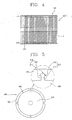
- Figure 4 is a front sectional view illustrating a rotor of a motor in accordance with a first embodiment of the present invention.
- Figure 5 is a side sectional view thereof.
- the rotor of the motor of the present invention includes a cylindrical magnet 500 having a plurality of first coupling portions 510 at 25 its inner circumferential surface of a cylindrical shape with a certain thickness, and a rotor core 600 inserted into the cylindrical magnet 500 and having second coupling portions 610 formed at its outer circumferential surface and fixedly coupled with the first coupling portions 510.
- the cylindrical magnet 500 includes a hollow cylindrical body 520 having a certain thickness, outer diameter and length, and at least one first coupling portion 510 formed at an inner circumferential surface of the hollow cylindrical body 520.
- the first coupling portions 510 have the same shape. However, the number of the first coupling portions 510, the shape of the first coupling portions 510 and the intervals of the first coupling portions 510 are adjustable to provide a secure coupling between the cylindrical magnet 500 and the rotor core 600.
- the first coupling portion 510 can be a recess or a protrusion.
- the first coupling portion 510 is a recess formed in a groove shape at the inner circumferential surface of the hollow cylindrical body 520.
- the groove penetrates the hollow cylindrical body 520 from one end to the other end of the hollow cylindrical body 520 along a longitudinal direction of the hollow cylindrical body 520.
- the groove in a cross-sectional view includes a groove side parallel portion 511 having a certain width and depth, and a groove side stopping portion 512 communicating with the groove side parallel portion 511 having a triangular shape.
- the rotor core 600 includes an filled cylindrical body 620 having an outer diameter corresponding to an inner diameter of the cylindrical magnet 500 and a length corresponding to that of the cylindrical magnet 500, and at least one second coupling portion 610 coupled with the at least one first coupling portion 510.
- the number of the second coupling portions 610 formed corresponds to that of the first coupling portions 510, and the second coupling portions 610 are formed at regular intervals.
- the first coupling portions 510 have the same shape with each other.
- the second coupling portion 610 can be a recess or a protrusion complementary to the first coupling portion 510.
- the second coupling portion 610 is a protrusion formed at an outer circumferential surface of the filled cylindrical body 620.
- the protrusion is formed from one end to the other end of the filled cylindrical body 620 along a longitudinal direction of the filled cylindrical body 620.
- the protrusion in a cross-sectional view includes a protrusion side parallel portion 611 extending from the filled cylindrical body 620 and having a certain width and depth, and a protrusion side stopping portion 612 extending from the protrusion side parallel portion 611 having a triangular shape.
- first coupling portion 510 of the cylindrical magnet 500 is complementary to the second coupling portion 610 of the rotor core 600. If there are a plurality of first coupling portions and second coupling portions, some of the first and second coupling portions may be protrusions and the other of the first and second coupling portions may be recesses.
- the rotor core 600 is a lamination body in which a plurality of thin sheets (S) having a certain thickness are laminated.
- the laminated thin sheets (S) are fixedly coupled with each other by bolting or riveting.
- the rotor core 600 and the cylindrical magnet 500 are coupled with each other.
- the second coupling portions 610 of the rotor core 600 are engaged with the first coupling portions 510 of the cylindrical magnet 500.
- the first coupling portions 510 and the second coupling portions 610 are engaged with each other by forcible fitting, the rotor core 600 and the cylindrical magnet 500 are fixedly coupled with each other.
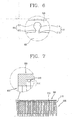
- the groove in a cross-sectional view includes a groove side parallel portion 513 and a groove side stopping portion 514 communicating with the groove side parallel portion 513 having a circular shape.
- the protrusion in a cross-sectional view includes a protrusion side parallel portion 613 extending from the outer circumferential surface of the filled cylindrical body 620 and having a certain thickness and length, and a protrusion side stopping portion 614 extending from the protrusion side parallel portion 613 having a circular shape.
- the first coupling portions 510 of the cylindrical magnet 500 and the second coupling portions 610 of the rotor core 600 can be implemented in various shapes.
- first coupling portions 510 of the cylindrical magnet 500 and the second coupling portions 610 of the rotor core 600 is illustrated in Figure 7.
- the second coupling portion has a protrusion protruding at the outer circumferential surface of the filled cylindrical body 620, and the protrusion is shorter than the filled cylindrical body 620.
- the first coupling portion has a recess in a groove shape formed at the inner circumferential surface of the hollow cylindrical body 520, and is shorter than the hollow cylindrical body 520.
- the length of the groove corresponds to that of the protrusion. That is, the groove does not penetrate through the longitudinal direction of the hollow cylindrical body 520 but has one end which stops the protrusion of the rotor core.
- the non-recess portion at one end of the cylindrical magnet 500 in the longitudinal direction of the cylindrical magnet 500 holds the protrusion 610 of the rotor core 600 in the longitudinal direction of the rotor core.
- the rotor of the motor which is obtained by coupling the rotor core 600 and the cylindrical magnet 500 with each other is inserted into a through hole of a stator (not illustrated).
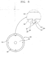
- Figure 8 is a side view illustrating a rotor of the motor in accordance with a second embodiment of the present invention.
- the rotor of the motor includes a cylindrical magnet 500 having a plurality of first coupling portions 530 at its inner circumferential surface of a cylindrical shape with a certain thickness, and a rotor core 600 inserted into the cylindrical magnet 500 and having second coupling portions 630 formed at its outer circumferential surface and fixedly coupled with the first coupling portions 530.
- the first coupling portion 530 has a protrusion
- the second coupling portion 630 has a recess in a groove shape corresponding to the protrusion.
- the cylindrical magnet 500 includes a hollow cylindrical body 540 having a certain thickness, outer diameter and length and first coupling portions 530 formed at the inner circumferential surface of the hollow cylindrical body 540.
- the first coupling portion 530 has a protrusion protruding at the inner circumferential surface of the hollow cylindrical body 540.
- the protrusion is formed from one end to the other end in a longitudinal direction of the hollow cylindrical body 540.
- the protrusion in a cross-sectional view includes a protrusion side parallel portion 531 extending from the inner circumferential surface of the hollow cylindrical body 540 and having a certain thickness and length and a protrusion side stopping portion 532 extending from the protrusion side parallel portion 531 and having a triangular shape.
- the rotor core 600 includes an filled cylindrical body 640 having an outer diameter corresponding to an inner diameter of the cylindrical magnet 500 and a length corresponding to that of the cylindrical magnet 500, and a plurality of second coupling portions 630 formed at an outer circumferential surface of the filled cylindrical body 640 and coupled with the first coupling portions 530.
- the second coupling portion 630 is formed as a recess in a groove shape at the outer circumferential surface of the filled cylindrical body 640.
- the number of the second coupling portions 630 corresponds to that of the first coupling portions 530.
- the second coupling portions 630 are formed at regular intervals.
- the first coupling portions 530 have the same shape with each other.
- the groove penetrates the filled cylindrical body 640 from one end to the other end along a longitudinal direction of the filled cylindrical body 640.
- the groove in a cross-sectional view includes a groove side parallel portion 631 having a certain width and depth and a groove side stopping portion 632 communicating with the groove side parallel portion 631 having a triangular shape.
- the protrusion in a cross-sectional view includes a protrusion side parallel portion 533 extending from the filled cylindrical body and having a certain width and depth and a protrusion side stopping portion 534 extending from the protrusion side parallel portion 533 having a circular shape.
- the groove in a cross-sectional view includes a groove side parallel portion 633 having a certain width and depth and a groove side stopping portion 634 communicating with the groove side parallel portion 633 having a circular shape.
- FIG 10 is a side view illustrating a rotor of the motor in accordance with a third embodiment of the present invention.
- the first cylindrical magnet 500 is divided into a plurality of parts based on the center of each of the first coupling portions 510 in the above-described first embodiment. Both ends of each sectional type magnet 550 having a circular arc are fixedly coupled with the second coupling portions 610.
- the first coupling portion 510 is divided in the longitudinal direction of the cylindrical magnet 500.
- Two adjacent magnets 550 form one first coupling portion at a junction between the two adjacent magnets 550.
- each of the two adjacent magnets 550 has a half portion of the first coupling portion at one end and another half portion of the first coupling portion at the other end.
- the first coupling portion is a recess.
- the first coupling portion may also be a protrusion formed by two adjacent magnets 550. Also, if there are a plurality of first coupling portions, some of the first coupling portions may be protrusions and the other of the first coupling portions may be recesses.
- Figure 11 is a perspective view sequentially illustrating a method for manufacturing the rotor of the motor in accordance with an embodiment of the present invention.
- the cylindrical magnet 500 is formed to have a plurality of first coupling portions 510 having a recess in a groove shape at an inner circumferential surface of a hollow cylindrical body with a certain.
- the rotor core 600 is formed to have a plurality of protruding second coupling portions 610 to be coupled with the first coupling portions 510 at its outer circumferential surface by laminating a plurality of thin sheets (S) having a predetermined shape and fixedly coupling the thin sheets (S) with each other.
- the thin sheets (S) constituting the lamination body are fixed by bolting or riveting.
- the rotor core 600 and the cylindrical magnet 500 are engaged with each other such that the first coupling portions 510 and the second coupling portions 610 are engaged with each other and fixed.
- the illustrated embodiments reduce the manufacturing time by excluding the use of an adhesive and the time to dry the adhesive because the cylindrical magnet 500 and the rotor core 600 are coupled with each other by engaging a plurality of first coupling portions 510 formed on the cylindrical magnet 500 and a plurality of second coupling portions 610 formed on the rotor core 600.
- the illustrated embodiments include one cylindrical magnet 500 and one rotor core 600, the number of assembly parts is reduced and assembly operation is simplified, thereby reducing manufacturing time.
- the cylindrical magnet 500 has the cylindrical shape.
- the cylindrical magnet 500 and the rotor core 600 are coupled with each other as the first coupling portions 510 formed on the cylindrical magnet 500 and a plurality of second coupling portions 610 formed on the rotor core 600 are engaged with each other.
- the two components are firmly coupled with each other to thereby prevent the two components from being separated from each other during the operation of the motor.
- the adhesive since the use of the adhesive is excluded, the contact between the rotor and the stator due to the protrusion of the adhesive is prevented.
- the magnet since the magnet has a cylindrical shape, an interval between the outer circumferential surface of the rotor and an inner wall of the through hole of the stator into which the rotor is inserted is minimized.
- the rotor of the motor and the manufacturing method thereof of as illustrated can increase assembly productivity because of the reduction in time for manufacturing the rotor of the motor, and can reduce the unit cost of assembly because of the reduction of the number of assembly parts.
- the rotor core 600 and the cylindrical magnet 500 are firmly coupled with each other, separation of parts and damage to parts may be prevented. Accordingly, the product reliability can be increased.
Landscapes
- Engineering & Computer Science (AREA)
- Power Engineering (AREA)
- Manufacturing & Machinery (AREA)
- Permanent Field Magnets Of Synchronous Machinery (AREA)
- Manufacture Of Motors, Generators (AREA)
- Iron Core Of Rotating Electric Machines (AREA)
Abstract
Description
- The present invention relates to a motor, and particularly, to a rotor of a motor and a manufacturing method thereof which can simplify assembly operation, reduce manufacturing time and allow firm coupling of a magnet.
- A motor is a device for converting electric energy into kinetic energy, and is used as a power source of almost every machine. The motor is classified into a DC motor, a BLDC motor (Brush Less Direct Current Motor), an induction motor, a synchronous motor, a universal motor or the like.
- In general, the BLDC motor includes a stator in which a coil winds around a laminated core, a rotor having a magnet and rotatably inserted into a through hole formed inside the stator, and a hole sensor for sensing a pole of the rotor magnet.
- In the BLDC motor, the rotor is rotated by the interaction between a magnetic field generated by an electric current applied to the wound coil and a magnetic field generated by the magnet of the rotor. The hole sensor senses the pole of the magnet and controls the electric current supplied to the coil.
- Figure 1 is a sectional view illustrating a rotor of an SPM (Surface Permanent Magnet) type BLDC motor. Figure 2 is a side view of the rotor. As illustrated therein, the rotor of the BLDC motor includes a
cylindrical rotor core 100 in which a plurality of disc-shaped sheets 110 having uniform thickness are laminated to have a certain length and an outer diameter, and a plurality of curved plate-shaped magnets 200 having a certain thickness and attached to an outer circumferential surface of therotor core 100. The disc-shaped sheet 110 is formed of silicon steel. The disc-shaped sheets 110 laminated in a cylindrical shape are fixedly coupled with each other by a welding or bolting. - There are four curved plate-
shaped magnets 200. A radius of curvature of themagnet 200 corresponds to that of therotor core 100. When the four curved plate-shaped magnets 200 are attached to the outer circumferential surface of therotor core 100, the four curved plate-shaped magnets form a cylindrical shape. That is, the four curved plate-shaped magnets 200 completely cover the outer circumferential surface of therotor core 100. - The curved plate-
shaped magnets 200 are attached to the outer circumferential surface of therotor core 100 by an adhesive 210. Ashaft hole 120 is penetratingly formed at the center of therotor core 100.Parts - A method for manufacturing the rotor of the BLDC motor is as follows. First, as illustrated in Figure 3, a plurality of disc-
shaped sheets 110 are manufactured by a press process and are laminated to form a cylindrical shape. The disc-shaped sheets 110 are fixedly coupled with each other by bolting or welding, and so on, thereby manufacturing therotor core 100. - After the
adhesive 210 is applied to the outer circumferential surface of therotor core 100, the curved plate-shaped magnets 200 are attached to the outer circumferential surface of therotor core 100. Then, theadhesive 210 is dried. Themagnets 200 are attached to the outer circumferential surface of therotor core 100 after the curved plate-shaped magnets 200 are magnetized. The curved plate-shaped magnets 200 may be attached to therotor core 100 and then magnetized. - However, since in the rotor of the conventional BLDC motor, several curved plate-
shaped magnets 200 are adhered and fixed to the outer circumferential surface by using theadhesive 210, a series of adhering processes to adhere the curved plate-shaped magnets 200 and a process of drying theadhesive 210 are required, thereby increasing the manufacturing time. Accordingly, assembly productivity of the rotor of the motor is significantly deteriorated. - In addition, since the curved plate-
shaped magnets 200 are attached to the outer circumferential surface of therotor core 100 by theadhesive 210, the defective adhering of curved plate-shaped magnets 200 is more likely to occur. In this case, the curved plate-shaped magnets 200 are apart from therotor core 100 to cause the damage to the motor during the operation of the motor. - In addition, the rotor is inserted into the through hole of the stator. The narrower an interval between the outer circumferential surface of the rotor and an inner circumferential surface of the through hole is, the higher the motor efficiency is. However, the curved plate-
shaped magnets 200 are attached to the outer circumferential surface of therotor core 100. If there is a large amount of theadhesive 210, theadhesive 210 protrudes from between the curved plate-shaped magnets 200 and is hardened. Thus, the hardenedadhesive 210 comes in contact with an inner wall of the through hole of the stator during the operation of the motor to thereby increase rotary resistance of the rotor. - Therefore, an object of the present invention is to provide a rotor of a motor and a manufacturing method thereof which can simplify assembly operation and reduce manufacturing time.
- It is another object of the present invention to provide a rotor of a motor and a manufacturing method thereof which allows the firm coupling of a magnet to a rotor core and prevents the contact between the stator and the rotor.
- To achieve these and other advantages and in accordance with the purpose of the present invention, as embodied and broadly described herein, there is provided a rotor of a motor, comprising: a cylindrical magnet having at least one first coupling portion at an inner circumferential surface of the cylindrical magnet; and a rotor core coupled with the cylindrical magnet, the rotor core having at least one second coupling portion at an outer circumferential surface of the rotor core, the at least one second coupling portion being engaged with the corresponding at least one first coupling portion.
- To achieve these and other advantages and in accordance with the purpose of the present invention, as embodied and broadly described herein, there is provided a method for manufacturing a rotor of a motor, comprising: forming a cylindrical magnet to have at least one first coupling portion at an inner circumferential surface of the cylindrical magnet; forming a rotor core to have at least one second coupling portion at an outer circumferential surface of the rotor core; and coupling the rotor core and the cylindrical magnet so as to engage the at least one first coupling portion with the at least one second coupling portion.
- The foregoing and other objects, features, aspects and advantages of the present invention will become more apparent from the following detailed description of the present invention when taken in conjunction with the accompanying drawings.
- The accompanying drawings, which are included to provide a further understanding of the invention and are incorporated in and constitute a part of this specification, illustrate embodiments of the invention and together with the description serve to explain the principles of the invention.
In the drawings: - Figures 1 and 2 are a front sectional view and a side view illustrating a rotor of a BLDC motor in accordance with the conventional art;
- Figure 3, is a perspective view sequentially illustrating a method for manufacturing the rotor of the BLDC motor;
- Figures 4. and 5 are a front sectional view and a side view illustrating a rotor of a motor in accordance with a first embodiment of the present invention;
- Figure 6 is a sectional view illustrating one modified example of first coupling portions and second coupling portions of the rotor of the motor in accordance with the first embodiment of the present invention;
- Figure 7 is a sectional view illustrating another modified example of first coupling portions and second coupling portions of the rotor of the motor in accordance with the first embodiment of the present invention;
- Figure 8 is a side view illustrating a rotor of the motor in accordance with a second embodiment of the present invention;
- Figure 9 is a sectional view illustrating a modified example of a first coupling portion and a second coupling portion in accordance with the second embodiment of the present invention;
- Figure 10 is a side view illustrating a rotor of the motor in accordance with a third embodiment of the present invention; and
- Figure 11 is a perspective view schematically illustrating a method for manufacturing the rotor of the motor in accordance with an embodiment of the present invention.
- Hereinafter, a rotor of a motor and a manufacturing method thereof in accordance with the present invention will be described in detail according to embodiments illustrated in the accompanying drawings.
- Figure 4 is a front sectional view illustrating a rotor of a motor in accordance with a first embodiment of the present invention. Figure 5 is a side sectional view thereof. As illustrated therein, the rotor of the motor of the present invention includes a
cylindrical magnet 500 having a plurality offirst coupling portions 510 at 25 its inner circumferential surface of a cylindrical shape with a certain thickness, and arotor core 600 inserted into thecylindrical magnet 500 and havingsecond coupling portions 610 formed at its outer circumferential surface and fixedly coupled with thefirst coupling portions 510. - The
cylindrical magnet 500 includes a hollowcylindrical body 520 having a certain thickness, outer diameter and length, and at least onefirst coupling portion 510 formed at an inner circumferential surface of the hollowcylindrical body 520. In the illustrated embodiment, there are fourfirst coupling portions 510 formed at regular intervals. In the illustrated embodiment, thefirst coupling portions 510 have the same shape. However, the number of thefirst coupling portions 510, the shape of thefirst coupling portions 510 and the intervals of thefirst coupling portions 510 are adjustable to provide a secure coupling between thecylindrical magnet 500 and therotor core 600. - The
first coupling portion 510 can be a recess or a protrusion. In this embodiment, thefirst coupling portion 510 is a recess formed in a groove shape at the inner circumferential surface of the hollowcylindrical body 520. The groove penetrates the hollowcylindrical body 520 from one end to the other end of the hollowcylindrical body 520 along a longitudinal direction of the hollowcylindrical body 520. When the groove is sectioned along the circumferential direction of the hollowcylindrical body 520, the groove in a cross-sectional view includes a groove sideparallel portion 511 having a certain width and depth, and a grooveside stopping portion 512 communicating with the groove sideparallel portion 511 having a triangular shape. - The
rotor core 600 includes an filledcylindrical body 620 having an outer diameter corresponding to an inner diameter of thecylindrical magnet 500 and a length corresponding to that of thecylindrical magnet 500, and at least onesecond coupling portion 610 coupled with the at least onefirst coupling portion 510. The number of thesecond coupling portions 610 formed corresponds to that of thefirst coupling portions 510, and thesecond coupling portions 610 are formed at regular intervals. In the illustrated embodiment, thefirst coupling portions 510 have the same shape with each other. - The
second coupling portion 610 can be a recess or a protrusion complementary to thefirst coupling portion 510. In this embodiment, thesecond coupling portion 610 is a protrusion formed at an outer circumferential surface of the filledcylindrical body 620. The protrusion is formed from one end to the other end of the filledcylindrical body 620 along a longitudinal direction of the filledcylindrical body 620. When the protrusion is sectioned along the circumferential direction of the filledcylindrical body 620, the protrusion in a cross-sectional view includes a protrusion sideparallel portion 611 extending from the filledcylindrical body 620 and having a certain width and depth, and a protrusionside stopping portion 612 extending from the protrusion sideparallel portion 611 having a triangular shape. - That is, the
first coupling portion 510 of thecylindrical magnet 500 is complementary to thesecond coupling portion 610 of therotor core 600. If there are a plurality of first coupling portions and second coupling portions, some of the first and second coupling portions may be protrusions and the other of the first and second coupling portions may be recesses. - In an embodiment, the
rotor core 600 is a lamination body in which a plurality of thin sheets (S) having a certain thickness are laminated. In the lamination body, the laminated thin sheets (S) are fixedly coupled with each other by bolting or riveting. - When the
rotor core 600 is inserted into thecylindrical magnet 500, therotor core 600 and thecylindrical magnet 500 are coupled with each other. At the same time, thesecond coupling portions 610 of therotor core 600 are engaged with thefirst coupling portions 510 of thecylindrical magnet 500. As thefirst coupling portions 510 and thesecond coupling portions 610 are engaged with each other by forcible fitting, therotor core 600 and thecylindrical magnet 500 are fixedly coupled with each other. - Another modified example of the
first coupling portions 510 of thecylindrical magnet 500 and thesecond coupling portions 610 of therotor core 600 is illustrated in Figure 6. In this embodiment, the groove in a cross-sectional view includes a groove sideparallel portion 513 and a grooveside stopping portion 514 communicating with the groove sideparallel portion 513 having a circular shape. The protrusion in a cross-sectional view includes a protrusion sideparallel portion 613 extending from the outer circumferential surface of the filledcylindrical body 620 and having a certain thickness and length, and a protrusionside stopping portion 614 extending from the protrusion sideparallel portion 613 having a circular shape. Thefirst coupling portions 510 of thecylindrical magnet 500 and thesecond coupling portions 610 of therotor core 600 can be implemented in various shapes. - In addition, another modified example of the
first coupling portions 510 of thecylindrical magnet 500 and thesecond coupling portions 610 of therotor core 600 is illustrated in Figure 7. In this embodiment, the second coupling portion has a protrusion protruding at the outer circumferential surface of the filledcylindrical body 620, and the protrusion is shorter than the filledcylindrical body 620. The first coupling portion has a recess in a groove shape formed at the inner circumferential surface of the hollowcylindrical body 520, and is shorter than the hollowcylindrical body 520. - In the illustrated embodiment, the length of the groove corresponds to that of the protrusion. That is, the groove does not penetrate through the longitudinal direction of the hollow
cylindrical body 520 but has one end which stops the protrusion of the rotor core. In this embodiment, the non-recess portion at one end of thecylindrical magnet 500 in the longitudinal direction of thecylindrical magnet 500 holds theprotrusion 610 of therotor core 600 in the longitudinal direction of the rotor core. - The rotor of the motor which is obtained by coupling the
rotor core 600 and thecylindrical magnet 500 with each other is inserted into a through hole of a stator (not illustrated). - Figure 8 is a side view illustrating a rotor of the motor in accordance with a second embodiment of the present invention. As illustrated therein, the rotor of the motor includes a
cylindrical magnet 500 having a plurality offirst coupling portions 530 at its inner circumferential surface of a cylindrical shape with a certain thickness, and arotor core 600 inserted into thecylindrical magnet 500 and havingsecond coupling portions 630 formed at its outer circumferential surface and fixedly coupled with thefirst coupling portions 530. Thefirst coupling portion 530 has a protrusion, and thesecond coupling portion 630 has a recess in a groove shape corresponding to the protrusion. - The
cylindrical magnet 500 includes a hollowcylindrical body 540 having a certain thickness, outer diameter and length andfirst coupling portions 530 formed at the inner circumferential surface of the hollowcylindrical body 540. Thefirst coupling portion 530 has a protrusion protruding at the inner circumferential surface of the hollowcylindrical body 540. - The protrusion is formed from one end to the other end in a longitudinal direction of the hollow
cylindrical body 540. As the protrusion is sectioned along the circumferential direction of the hollowcylindrical body 540, the protrusion in a cross-sectional view includes a protrusion sideparallel portion 531 extending from the inner circumferential surface of the hollowcylindrical body 540 and having a certain thickness and length and a protrusionside stopping portion 532 extending from the protrusion sideparallel portion 531 and having a triangular shape. - The
rotor core 600 includes an filledcylindrical body 640 having an outer diameter corresponding to an inner diameter of thecylindrical magnet 500 and a length corresponding to that of thecylindrical magnet 500, and a plurality ofsecond coupling portions 630 formed at an outer circumferential surface of the filledcylindrical body 640 and coupled with thefirst coupling portions 530. Thesecond coupling portion 630 is formed as a recess in a groove shape at the outer circumferential surface of the filledcylindrical body 640. - In this embodiment, the number of the
second coupling portions 630 corresponds to that of thefirst coupling portions 530. Thesecond coupling portions 630 are formed at regular intervals. In addition, thefirst coupling portions 530 have the same shape with each other. - The groove penetrates the filled
cylindrical body 640 from one end to the other end along a longitudinal direction of the filledcylindrical body 640. As the groove is sectioned along the circumferential direction of the filledcylindrical body 640, the groove in a cross-sectional view includes a groove sideparallel portion 631 having a certain width and depth and a grooveside stopping portion 632 communicating with the groove sideparallel portion 631 having a triangular shape. - Another modified example of the
first coupling portions 530 of thecylindrical magnet 500 and thesecond coupling portions 630 of thecore 600 is illustrated in Figure 9. In this embodiment, the protrusion in a cross-sectional view includes a protrusion sideparallel portion 533 extending from the filled cylindrical body and having a certain width and depth and a protrusionside stopping portion 534 extending from the protrusion sideparallel portion 533 having a circular shape. - The groove in a cross-sectional view includes a groove side
parallel portion 633 having a certain width and depth and a grooveside stopping portion 634 communicating with the groove sideparallel portion 633 having a circular shape. - Figure 10 is a side view illustrating a rotor of the motor in accordance with a third embodiment of the present invention. As illustrated therein, in the rotor of the motor, the first
cylindrical magnet 500 is divided into a plurality of parts based on the center of each of thefirst coupling portions 510 in the above-described first embodiment. Both ends of eachsectional type magnet 550 having a circular arc are fixedly coupled with thesecond coupling portions 610. Thefirst coupling portion 510 is divided in the longitudinal direction of thecylindrical magnet 500. - Two
adjacent magnets 550 form one first coupling portion at a junction between the twoadjacent magnets 550. In the illustrated embodiment, each of the twoadjacent magnets 550 has a half portion of the first coupling portion at one end and another half portion of the first coupling portion at the other end. In this embodiment, the first coupling portion is a recess. However, the first coupling portion may also be a protrusion formed by twoadjacent magnets 550. Also, if there are a plurality of first coupling portions, some of the first coupling portions may be protrusions and the other of the first coupling portions may be recesses. - Figure 11 is a perspective view sequentially illustrating a method for manufacturing the rotor of the motor in accordance with an embodiment of the present invention. As illustrated therein, in the method for manufacturing the rotor of the motor, the
cylindrical magnet 500 is formed to have a plurality offirst coupling portions 510 having a recess in a groove shape at an inner circumferential surface of a hollow cylindrical body with a certain. - The
rotor core 600 is formed to have a plurality of protrudingsecond coupling portions 610 to be coupled with thefirst coupling portions 510 at its outer circumferential surface by laminating a plurality of thin sheets (S) having a predetermined shape and fixedly coupling the thin sheets (S) with each other. The thin sheets (S) constituting the lamination body are fixed by bolting or riveting. - Subsequently, the
rotor core 600 and thecylindrical magnet 500 are engaged with each other such that thefirst coupling portions 510 and thesecond coupling portions 610 are engaged with each other and fixed. - The illustrated embodiments reduce the manufacturing time by excluding the use of an adhesive and the time to dry the adhesive because the
cylindrical magnet 500 and therotor core 600 are coupled with each other by engaging a plurality offirst coupling portions 510 formed on thecylindrical magnet 500 and a plurality ofsecond coupling portions 610 formed on therotor core 600. In addition, since some of the illustrated embodiments include onecylindrical magnet 500 and onerotor core 600, the number of assembly parts is reduced and assembly operation is simplified, thereby reducing manufacturing time. - In the illustrated embodiments, the
cylindrical magnet 500 has the cylindrical shape. In addition, thecylindrical magnet 500 and therotor core 600 are coupled with each other as thefirst coupling portions 510 formed on thecylindrical magnet 500 and a plurality ofsecond coupling portions 610 formed on therotor core 600 are engaged with each other. Thus, the two components are firmly coupled with each other to thereby prevent the two components from being separated from each other during the operation of the motor. In addition, since the use of the adhesive is excluded, the contact between the rotor and the stator due to the protrusion of the adhesive is prevented. Also, since the magnet has a cylindrical shape, an interval between the outer circumferential surface of the rotor and an inner wall of the through hole of the stator into which the rotor is inserted is minimized. - As described, the rotor of the motor and the manufacturing method thereof of as illustrated can increase assembly productivity because of the reduction in time for manufacturing the rotor of the motor, and can reduce the unit cost of assembly because of the reduction of the number of assembly parts.
- In addition, since the
rotor core 600 and thecylindrical magnet 500 are firmly coupled with each other, separation of parts and damage to parts may be prevented. Accordingly, the product reliability can be increased. - As the present invention may be embodied in several forms without departing from the spirit or essential characteristics thereof, it should also be understood that the above-described embodiments are not limited by any of the details of the foregoing description, unless otherwise specified, but rather should be construed broadly within its spirit and scope as defined in the appended claims, and therefore all changes and modifications that fall within the metes and bounds of the claims, or equivalence of such metes and bounds are therefore intended to be embraced by the appended claims.
Claims (20)
- A rotor of a motor, comprising:a cylindrical magnet having at least one first coupling portion at an inner circumferential surface of the cylindrical magnet; anda rotor core coupled with the cylindrical magnet, the rotor core having at least one second coupling portion at an outer circumferential surface of the rotor core, the at least one second coupling portion being engaged with the corresponding at least one first coupling portion.
- The rotor of claim 1, wherein the at least one first coupling portion is one of a recess and a protrusion at the inner circumferential surface of the cylindrical magnet, and the at least one second coupling portion is the other one of the recess and the protrusion engaged with the corresponding at least one first coupling portion.
- The rotor of claim 2, wherein the recess is complementary to the corresponding protrusion to receive the corresponding protrusion.
- The rotor of claim 2, wherein the cylindrical magnet is an integral, single piece.
- The rotor of claim 2, wherein the cylindrical magnet includes a plurality of pieces surrounding the outer circumferential surface of the rotor core, two adjacent pieces of the cylindrical magnet forming the one of the recess and the protrusion at a junction between the two adjacent pieces.
- The rotor of claim 5, wherein each of the two adjacent pieces has a half portion of the one of the recess and the protrusion at one end corresponding to the junction.
- The rotor of claim 2, wherein the recess has a recess extending portion and a recess stopping portion, the recess extending portion extending from one of the inner circumferential surface of the cylindrical magnet and the outer circumferential surface of the rotor core, the recess stopping portion extending from an end of the recess extending portion.
- The rotor of claim 7, wherein the protrusion has a protrusion extending portion and a protrusion stopping portion, the protrusion extending portion extending from the other one of the inner circumferential surface of the cylindrical magnet and the outer circumferential surface of the rotor core, the protrusion stopping portion extending from an end of the protrusion extending portion.
- The rotor of claim 2, wherein the recess and the protrusion are respectively along a longitudinal direction of one of the cylindrical magnet and the rotor core.
- The rotor of claim 9, wherein the recess and the protrusion respectively have a same length as a length of the one of the cylindrical magnet and the rotor core in the longitudinal direction of the one of the cylindrical magnet and the rotor core.
- The rotor of claim 9, wherein the recess and the protrusion respectively have a shorter length than a length of the one of the cylindrical magnet and the rotor core in the longitudinal direction of the one of the cylindrical magnet and the rotor core.
- A method for manufacturing a rotor of a motor, comprising:forming a cylindrical magnet to have at least one first coupling portion at an inner circumferential surface of the cylindrical magnet;forming a rotor core to have at least one second coupling portion at an outer circumferential surface of the rotor core; andcoupling the rotor core and the cylindrical magnet so as to engage the at least one first coupling portion with the at least one second coupling portion.
- The method of claim 12, wherein the step of forming the cylindrical magnet to have the at least one first coupling portion includes forming one of a recess and a protrusion at the inner circumferential surface of the cylindrical magnet as the at least one first coupling portion, and wherein the step of forming the rotor core to have the at least one second coupling portion includes forming the other one of the recess and the protrusion as the at least one second coupling portion.
- The method of claim 13, wherein the step of forming the cylindrical magnet includes forming the cylindrical magnet as an integral, single piece.
- The method of claim 13, wherein the step of forming the cylindrical magnet includes forming a plurality of pieces for the cylindrical magnet, and combining two adjacent pieces to form the one of the recess and the protrusion at a junction between the two adjacent pieces.
- The method of claim 13, wherein the step of forming the recess includes:forming a recess extending portion extending from one of the inner circumferential surface of the cylindrical magnet and the outer circumferential surface of the rotor core; andforming a recess stopping portion extending from an end of the recess extending portion.
- The method of claim 16, wherein the step of forming the protrusion includes:forming a protrusion extending portion extending from the other one of the inner circumferential surface of the cylindrical magnet and the outer circumferential surface of the rotor core; andforming a protrusion stopping portion extending from an end of the protrusion extending portion.
- The method of claim 13, wherein the steps of forming the recess and the protrusion include forming the recess and the protrusion respectively along a longitudinal direction of one of the cylindrical magnet and the rotor core.
- The method of claim 18, wherein the steps of forming the recess and the protrusion include forming the recess and the protrusion respectively to have a same length as a length of the one of the cylindrical magnet and the rotor core in the longitudinal direction of the one of the cylindrical magnet and the rotor core.
- The method of claim 18, wherein the steps of forming the recess and the protrusion include forming the recess and the protrusion respectively to have a shorter length than a length of the one of the cylindrical magnet and the rotor core in the longitudinal direction of the one of the cylindrical magnet and the rotor core.
Applications Claiming Priority (1)
| Application Number | Priority Date | Filing Date | Title |
|---|---|---|---|
| KR1020050053186A KR100664065B1 (en) | 2005-06-20 | 2005-06-20 | Magnet fixing structure of electric motor |
Related Child Applications (1)
| Application Number | Title | Priority Date | Filing Date |
|---|---|---|---|
| EP12192395.7 Division-Into | 2012-11-13 |
Publications (3)
| Publication Number | Publication Date |
|---|---|
| EP1737105A2 true EP1737105A2 (en) | 2006-12-27 |
| EP1737105A3 EP1737105A3 (en) | 2010-06-23 |
| EP1737105B1 EP1737105B1 (en) | 2013-05-01 |
Family
ID=37192510
Family Applications (1)
| Application Number | Title | Priority Date | Filing Date |
|---|---|---|---|
| EP06001320.8A Ceased EP1737105B1 (en) | 2005-06-20 | 2006-01-23 | Rotor of motor and manufacturing method thereof |
Country Status (6)
| Country | Link |
|---|---|
| US (1) | US7348704B2 (en) |
| EP (1) | EP1737105B1 (en) |
| JP (1) | JP2007006689A (en) |
| KR (1) | KR100664065B1 (en) |
| CN (1) | CN100547882C (en) |
| AU (1) | AU2006200188B2 (en) |
Cited By (7)
| Publication number | Priority date | Publication date | Assignee | Title |
|---|---|---|---|---|
| WO2009021634A1 (en) * | 2007-08-15 | 2009-02-19 | Sew-Eurodrive Gmbh & Co. Kg | Electric motor and method for the production of an electric motor |
| EP2034589A3 (en) * | 2007-08-16 | 2011-05-25 | Young-Chun Jeung | Rotor of brushless motor |
| WO2015110188A3 (en) * | 2014-01-22 | 2015-10-22 | Volkswagen Aktiengesellschaft | Permanent magnet element and a rotor comprising same |
| EP2911274A3 (en) * | 2014-02-19 | 2015-12-23 | Portescap SA | Magnet tiles assembly |
| EP3142227A4 (en) * | 2014-05-06 | 2018-01-24 | Lin, Sheng-Lian | Motor |
| WO2021104765A1 (en) * | 2019-11-28 | 2021-06-03 | Robert Bosch Gmbh | Rotor for an electric machine and method for producing a rotor |
| IT202100023435A1 (en) | 2021-09-10 | 2023-03-10 | Hpe S R L | PERMANENT MAGNET ROTOR FOR A ROTATING ELECTRIC MACHINE |
Families Citing this family (21)
| Publication number | Priority date | Publication date | Assignee | Title |
|---|---|---|---|---|
| EP2371967B1 (en) | 2005-03-18 | 2015-06-03 | DSM IP Assets B.V. | Production of carotenoids in oleaginous yeast and fungi |
| US8691555B2 (en) | 2006-09-28 | 2014-04-08 | Dsm Ip Assests B.V. | Production of carotenoids in oleaginous yeast and fungi |
| TWI424803B (en) * | 2008-06-11 | 2014-01-21 | System General Corp | End cover board and motor rotor having the end cover board |
| US20100052457A1 (en) * | 2008-08-29 | 2010-03-04 | Brahmavar Subhash M | Methods and apparatus for fabrication of electric motors |
| KR101279774B1 (en) | 2009-03-30 | 2013-07-04 | 주식회사 만도 | Torque Rotor and Manufacturing Method of The Same |
| CN102306964A (en) * | 2011-09-13 | 2012-01-04 | 陈强 | Permanent magnet motor rotor |
| US9130426B2 (en) * | 2011-10-31 | 2015-09-08 | Regal Beloit America, Inc. | Permanent magnet rotors and methods of assembling the same |
| FR3002378B1 (en) * | 2013-02-20 | 2016-06-10 | Manutrans | MOBILE PIECE MAGNETS FOR SYNCHRONOUS MACHINE WITH PERMANENT MAGNETS. |
| US20140239764A1 (en) * | 2013-02-27 | 2014-08-28 | Regal Beloit America, Inc. | Laminated rotor with improved magnet adhesion and method of fabricating |
| US9735646B2 (en) * | 2013-08-16 | 2017-08-15 | Thomson Industries, Inc. | Injection molded blank for lead screw, rotor-blank assembly and method for producing same |
| US9837867B2 (en) * | 2014-07-21 | 2017-12-05 | Regal Beloit America, Inc. | Electric machine, rotor and associated method |
| EP2991195A1 (en) * | 2014-09-01 | 2016-03-02 | Siemens Aktiengesellschaft | Permanently excited dynamoelectric machine |
| CN104779723B (en) * | 2015-04-29 | 2017-06-23 | 湘潭电机股份有限公司 | A kind of surface-mounted permanent magnet machine rotor and motor |
| CN115483776A (en) | 2016-02-19 | 2022-12-16 | 莫戈公司 | Rotor assembly of electric motor |
| JP6464114B2 (en) * | 2016-05-20 | 2019-02-06 | ファナック株式会社 | Rotor structure of rotating electric machine and rotating electric machine |
| JP6925818B2 (en) * | 2017-02-14 | 2021-08-25 | 日本電産サンキョー株式会社 | Motor rotors, motors, and pumping equipment |
| JP2020088883A (en) * | 2018-11-15 | 2020-06-04 | Dmg森精機株式会社 | Rotor |
| CN110838767B (en) * | 2019-11-27 | 2021-10-19 | 珠海格力电器股份有限公司 | Slot-pole matching scheme Adjustable rotor core, rotor and motor |
| CN112134425B (en) * | 2020-08-12 | 2023-04-18 | 浙江迪贝电气股份有限公司 | Method for manufacturing rotor core of permanent magnet motor |
| EP4304062A4 (en) * | 2021-03-30 | 2025-02-19 | Aichi Steel Corporation | EXTERNAL ROTOR AND EXTERNAL ROTOR ELECTRIC MOTOR |
| JP2022155442A (en) * | 2021-03-30 | 2022-10-13 | 愛知製鋼株式会社 | Outer rotor and outer rotor type electric motor |
Family Cites Families (16)
| Publication number | Priority date | Publication date | Assignee | Title |
|---|---|---|---|---|
| US3810056A (en) * | 1972-08-28 | 1974-05-07 | Outboard Marine Corp | Non-magnetized ceramic magnetic assembly |
| JPS5887476A (en) * | 1981-11-20 | 1983-05-25 | Natl Space Dev Agency Japan<Nasda> | Generating device for reference signal in video band of synthetic aperture radar |
| JPS63100974U (en) * | 1986-12-18 | 1988-06-30 | ||
| GB2217924B (en) * | 1988-04-25 | 1992-10-07 | Matsushita Electric Works Ltd | Permanent magnet rotor |
| JPH0295150A (en) * | 1988-09-27 | 1990-04-05 | Matsushita Electric Works Ltd | Permanent magnet rotor |
| JPH02119544A (en) * | 1988-10-26 | 1990-05-07 | Matsushita Electric Works Ltd | Permanent magnet rotor |
| GB9611263D0 (en) | 1995-07-14 | 1996-07-31 | Coin Controls | Inductor |
| US6034455A (en) * | 1997-04-10 | 2000-03-07 | Max Baermann Gmbh | Rotor for an electric motor |
| BR9702802A (en) * | 1997-08-28 | 2000-02-15 | Brasil Compressores Sa | Rotor for electric motor. |
| DE19905274A1 (en) * | 1999-02-09 | 2000-08-10 | Bosch Gmbh Robert | Rotation sensor |
| KR200214716Y1 (en) | 2000-09-05 | 2001-02-15 | 주식회사모아텍 | Magnet for rotors of a step motor |
| JP3661582B2 (en) * | 2000-09-28 | 2005-06-15 | 日産自動車株式会社 | Rotor for magnet motor |
| GB0130602D0 (en) * | 2001-12-21 | 2002-02-06 | Johnson Electric Sa | Brushless D.C. motor |
| JP3724447B2 (en) * | 2002-04-01 | 2005-12-07 | 日産自動車株式会社 | Rotor structure and manufacturing method thereof |
| JP2004096927A (en) * | 2002-09-02 | 2004-03-25 | Kokusan Denki Co Ltd | Outer rotor type motor |
| DE10307231A1 (en) * | 2003-02-14 | 2004-09-09 | Minebea Co., Ltd. | Brushless electric motor, has magnetic poles formed from magnetic molded body with terminating side on terminating body carrying magnetic poles |
-
2005
- 2005-06-20 KR KR1020050053186A patent/KR100664065B1/en not_active Expired - Fee Related
-
2006
- 2006-01-17 AU AU2006200188A patent/AU2006200188B2/en not_active Ceased
- 2006-01-23 EP EP06001320.8A patent/EP1737105B1/en not_active Ceased
- 2006-01-25 US US11/338,802 patent/US7348704B2/en not_active Expired - Lifetime
- 2006-02-07 JP JP2006029836A patent/JP2007006689A/en active Pending
- 2006-02-10 CN CNB2006100070809A patent/CN100547882C/en not_active Expired - Fee Related
Non-Patent Citations (1)
| Title |
|---|
| None |
Cited By (10)
| Publication number | Priority date | Publication date | Assignee | Title |
|---|---|---|---|---|
| WO2009021634A1 (en) * | 2007-08-15 | 2009-02-19 | Sew-Eurodrive Gmbh & Co. Kg | Electric motor and method for the production of an electric motor |
| EP2034589A3 (en) * | 2007-08-16 | 2011-05-25 | Young-Chun Jeung | Rotor of brushless motor |
| WO2015110188A3 (en) * | 2014-01-22 | 2015-10-22 | Volkswagen Aktiengesellschaft | Permanent magnet element and a rotor comprising same |
| EP2911274A3 (en) * | 2014-02-19 | 2015-12-23 | Portescap SA | Magnet tiles assembly |
| EP3142227A4 (en) * | 2014-05-06 | 2018-01-24 | Lin, Sheng-Lian | Motor |
| WO2021104765A1 (en) * | 2019-11-28 | 2021-06-03 | Robert Bosch Gmbh | Rotor for an electric machine and method for producing a rotor |
| CN114762219A (en) * | 2019-11-28 | 2022-07-15 | 罗伯特·博世有限公司 | Rotor for an electric machine and method for producing a rotor |
| US12119711B2 (en) | 2019-11-28 | 2024-10-15 | Robert Bosch Gmbh | Rotor for an electric machine and method for producing a rotor |
| IT202100023435A1 (en) | 2021-09-10 | 2023-03-10 | Hpe S R L | PERMANENT MAGNET ROTOR FOR A ROTATING ELECTRIC MACHINE |
| DE102022122783A1 (en) | 2021-09-10 | 2023-03-16 | Hpe S.R.L. | ROTOR WITH PERMANENT MAGNETS FOR A ROTATING ELECTRICAL MACHINE |
Also Published As
| Publication number | Publication date |
|---|---|
| JP2007006689A (en) | 2007-01-11 |
| KR20060133373A (en) | 2006-12-26 |
| US20060284506A1 (en) | 2006-12-21 |
| US7348704B2 (en) | 2008-03-25 |
| CN1885679A (en) | 2006-12-27 |
| AU2006200188A1 (en) | 2007-01-11 |
| AU2006200188B2 (en) | 2008-01-17 |
| CN100547882C (en) | 2009-10-07 |
| EP1737105A3 (en) | 2010-06-23 |
| KR100664065B1 (en) | 2007-01-03 |
| EP1737105B1 (en) | 2013-05-01 |
Similar Documents
| Publication | Publication Date | Title |
|---|---|---|
| US7348704B2 (en) | Rotor of motor and manufacturing method thereof | |
| EP2827474B1 (en) | Motor | |
| CN103872824B (en) | The rotor and buried magnet synchronous motor of buried magnet synchronous motor | |
| US7626304B2 (en) | Stator and motor, to which the stator is applied, and method of manufacturing the stator | |
| CN103378701A (en) | Rotor for a motor and a motor | |
| JP2003199303A (en) | Motor manufacturing method | |
| EP2619456B1 (en) | Electric motor-driven compressor for vehicle | |
| US6954018B2 (en) | Rotor of line start permanent magnet motor and manufacturing method thereof | |
| JP5665660B2 (en) | Permanent magnet rotating electric machine | |
| WO2014102950A1 (en) | Rotating electrical machine | |
| CN101861692A (en) | Laminated winding core, rotor and rotating electrical machine including same | |
| EP1521346A2 (en) | stator coiling and pole pieces | |
| CN104969446B (en) | Rotor arrangement for motor | |
| US20140152137A1 (en) | Motor with variable magnet flux | |
| JP2002209349A (en) | Rotor of permanent magnet type rotating electric machine | |
| CN107425624B (en) | Motor stator, motor and compressor | |
| JP2001218409A (en) | Stator of motor | |
| CN103762793A (en) | Production method of radial permanent-magnet rotor of drive motor of power-driven transport van | |
| CN111130240A (en) | Rotor and IPM motor using same | |
| JP2001218407A (en) | Stator of motor | |
| JP2004328859A (en) | Method of manufacturing rotor of motor and rotor of motor | |
| JP5691451B2 (en) | Rotor for rotating electrical machines | |
| JPH10225031A (en) | Magnet rotor and manufacturing method thereof | |
| JP2000245124A (en) | Smooth armature wound motor | |
| CN111181265A (en) | Distributed winding motor without inner slots and assembly method thereof |
Legal Events
| Date | Code | Title | Description |
|---|---|---|---|
| PUAI | Public reference made under article 153(3) epc to a published international application that has entered the european phase |
Free format text: ORIGINAL CODE: 0009012 |
|
| AK | Designated contracting states |
Kind code of ref document: A2 Designated state(s): AT BE BG CH CY CZ DE DK EE ES FI FR GB GR HU IE IS IT LI LT LU LV MC NL PL PT RO SE SI SK TR |
|
| AX | Request for extension of the european patent |
Extension state: AL BA HR MK YU |
|
| PUAL | Search report despatched |
Free format text: ORIGINAL CODE: 0009013 |
|
| AK | Designated contracting states |
Kind code of ref document: A3 Designated state(s): AT BE BG CH CY CZ DE DK EE ES FI FR GB GR HU IE IS IT LI LT LU LV MC NL PL PT RO SE SI SK TR |
|
| AX | Request for extension of the european patent |
Extension state: AL BA HR MK YU |
|
| 17P | Request for examination filed |
Effective date: 20101222 |
|
| AKX | Designation fees paid |
Designated state(s): DE FR GB |
|
| 17Q | First examination report despatched |
Effective date: 20110413 |
|
| GRAP | Despatch of communication of intention to grant a patent |
Free format text: ORIGINAL CODE: EPIDOSNIGR1 |
|
| GRAS | Grant fee paid |
Free format text: ORIGINAL CODE: EPIDOSNIGR3 |
|
| GRAA | (expected) grant |
Free format text: ORIGINAL CODE: 0009210 |
|
| AK | Designated contracting states |
Kind code of ref document: B1 Designated state(s): DE FR GB |
|
| REG | Reference to a national code |
Ref country code: GB Ref legal event code: FG4D |
|
| REG | Reference to a national code |
Ref country code: DE Ref legal event code: R096 Ref document number: 602006035989 Country of ref document: DE Effective date: 20130627 |
|
| PLBE | No opposition filed within time limit |
Free format text: ORIGINAL CODE: 0009261 |
|
| STAA | Information on the status of an ep patent application or granted ep patent |
Free format text: STATUS: NO OPPOSITION FILED WITHIN TIME LIMIT |
|
| 26N | No opposition filed |
Effective date: 20140204 |
|
| REG | Reference to a national code |
Ref country code: DE Ref legal event code: R097 Ref document number: 602006035989 Country of ref document: DE Effective date: 20140204 |
|
| REG | Reference to a national code |
Ref country code: FR Ref legal event code: PLFP Year of fee payment: 11 |
|
| REG | Reference to a national code |
Ref country code: FR Ref legal event code: PLFP Year of fee payment: 12 |
|
| REG | Reference to a national code |
Ref country code: FR Ref legal event code: PLFP Year of fee payment: 13 |
|
| PGFP | Annual fee paid to national office [announced via postgrant information from national office to epo] |
Ref country code: GB Payment date: 20171206 Year of fee payment: 13 |
|
| GBPC | Gb: european patent ceased through non-payment of renewal fee |
Effective date: 20190123 |
|
| PG25 | Lapsed in a contracting state [announced via postgrant information from national office to epo] |
Ref country code: GB Free format text: LAPSE BECAUSE OF NON-PAYMENT OF DUE FEES Effective date: 20190123 |
|
| REG | Reference to a national code |
Ref country code: FR Ref legal event code: PLFP Year of fee payment: 18 |
|
| PGFP | Annual fee paid to national office [announced via postgrant information from national office to epo] |
Ref country code: FR Payment date: 20221205 Year of fee payment: 18 |
|
| PGFP | Annual fee paid to national office [announced via postgrant information from national office to epo] |
Ref country code: DE Payment date: 20221205 Year of fee payment: 18 |
|
| REG | Reference to a national code |
Ref country code: DE Ref legal event code: R119 Ref document number: 602006035989 Country of ref document: DE |
|
| PG25 | Lapsed in a contracting state [announced via postgrant information from national office to epo] |
Ref country code: DE Free format text: LAPSE BECAUSE OF NON-PAYMENT OF DUE FEES Effective date: 20240801 |
|
| PG25 | Lapsed in a contracting state [announced via postgrant information from national office to epo] |
Ref country code: FR Free format text: LAPSE BECAUSE OF NON-PAYMENT OF DUE FEES Effective date: 20240131 |
|
| PG25 | Lapsed in a contracting state [announced via postgrant information from national office to epo] |
Ref country code: FR Free format text: LAPSE BECAUSE OF NON-PAYMENT OF DUE FEES Effective date: 20240131 Ref country code: DE Free format text: LAPSE BECAUSE OF NON-PAYMENT OF DUE FEES Effective date: 20240801 |