EP1736799B1 - Ultrasonic transmission/reception condition optimization method, corresponding program, and ultrasonic diagnostic apparatus - Google Patents
Ultrasonic transmission/reception condition optimization method, corresponding program, and ultrasonic diagnostic apparatus Download PDFInfo
- Publication number
- EP1736799B1 EP1736799B1 EP06012290A EP06012290A EP1736799B1 EP 1736799 B1 EP1736799 B1 EP 1736799B1 EP 06012290 A EP06012290 A EP 06012290A EP 06012290 A EP06012290 A EP 06012290A EP 1736799 B1 EP1736799 B1 EP 1736799B1
- Authority
- EP
- European Patent Office
- Prior art keywords
- ultrasonic
- delay time
- weighting coefficient
- ultrasonic transducer
- transducers
- Prior art date
- Legal status (The legal status is an assumption and is not a legal conclusion. Google has not performed a legal analysis and makes no representation as to the accuracy of the status listed.)
- Active
Links
Images

Classifications
-
- G—PHYSICS
- G01—MEASURING; TESTING
- G01S—RADIO DIRECTION-FINDING; RADIO NAVIGATION; DETERMINING DISTANCE OR VELOCITY BY USE OF RADIO WAVES; LOCATING OR PRESENCE-DETECTING BY USE OF THE REFLECTION OR RERADIATION OF RADIO WAVES; ANALOGOUS ARRANGEMENTS USING OTHER WAVES
- G01S15/00—Systems using the reflection or reradiation of acoustic waves, e.g. sonar systems
- G01S15/88—Sonar systems specially adapted for specific applications
- G01S15/89—Sonar systems specially adapted for specific applications for mapping or imaging
- G01S15/8906—Short-range imaging systems; Acoustic microscope systems using pulse-echo techniques
- G01S15/8909—Short-range imaging systems; Acoustic microscope systems using pulse-echo techniques using a static transducer configuration
- G01S15/8915—Short-range imaging systems; Acoustic microscope systems using pulse-echo techniques using a static transducer configuration using a transducer array
- G01S15/8925—Short-range imaging systems; Acoustic microscope systems using pulse-echo techniques using a static transducer configuration using a transducer array the array being a two-dimensional transducer configuration, i.e. matrix or orthogonal linear arrays
-
- G—PHYSICS
- G10—MUSICAL INSTRUMENTS; ACOUSTICS
- G10K—SOUND-PRODUCING DEVICES; METHODS OR DEVICES FOR PROTECTING AGAINST, OR FOR DAMPING, NOISE OR OTHER ACOUSTIC WAVES IN GENERAL; ACOUSTICS NOT OTHERWISE PROVIDED FOR
- G10K11/00—Methods or devices for transmitting, conducting or directing sound in general; Methods or devices for protecting against, or for damping, noise or other acoustic waves in general
- G10K11/18—Methods or devices for transmitting, conducting or directing sound
- G10K11/26—Sound-focusing or directing, e.g. scanning
- G10K11/34—Sound-focusing or directing, e.g. scanning using electrical steering of transducer arrays, e.g. beam steering
- G10K11/341—Circuits therefor
- G10K11/346—Circuits therefor using phase variation
-
- G—PHYSICS
- G01—MEASURING; TESTING
- G01S—RADIO DIRECTION-FINDING; RADIO NAVIGATION; DETERMINING DISTANCE OR VELOCITY BY USE OF RADIO WAVES; LOCATING OR PRESENCE-DETECTING BY USE OF THE REFLECTION OR RERADIATION OF RADIO WAVES; ANALOGOUS ARRANGEMENTS USING OTHER WAVES
- G01S7/00—Details of systems according to groups G01S13/00, G01S15/00, G01S17/00
- G01S7/52—Details of systems according to groups G01S13/00, G01S15/00, G01S17/00 of systems according to group G01S15/00
- G01S7/52017—Details of systems according to groups G01S13/00, G01S15/00, G01S17/00 of systems according to group G01S15/00 particularly adapted to short-range imaging
- G01S7/52046—Techniques for image enhancement involving transmitter or receiver
- G01S7/52047—Techniques for image enhancement involving transmitter or receiver for elimination of side lobes or of grating lobes; for increasing resolving power
-
- G—PHYSICS
- G01—MEASURING; TESTING
- G01S—RADIO DIRECTION-FINDING; RADIO NAVIGATION; DETERMINING DISTANCE OR VELOCITY BY USE OF RADIO WAVES; LOCATING OR PRESENCE-DETECTING BY USE OF THE REFLECTION OR RERADIATION OF RADIO WAVES; ANALOGOUS ARRANGEMENTS USING OTHER WAVES
- G01S7/00—Details of systems according to groups G01S13/00, G01S15/00, G01S17/00
- G01S7/52—Details of systems according to groups G01S13/00, G01S15/00, G01S17/00 of systems according to group G01S15/00
- G01S7/52017—Details of systems according to groups G01S13/00, G01S15/00, G01S17/00 of systems according to group G01S15/00 particularly adapted to short-range imaging
- G01S7/5205—Means for monitoring or calibrating
Definitions
- the present invention relates to the optimization of beam deflection in ultrasonic transmission/reception using a two-dimensional ultrasonic probe having, for example, ultrasonic transducers arranged in a two-dimensional matrix, a delay time for beam convergence, a weighting coefficient used in echo signal addition processing, and the like.
- An ultrasonic diagnostic apparatus is a medical image device which noninvasively obtains a tomogram of a soft tissue in a living body from the body surface by an ultrasonic pulse reflection method.
- This ultrasonic diagnostic apparatus has advantages of being smaller in size, more inexpensive, and safer because of no exposure to X-rays and the like than other medical image devices, and of being capable of blood flow imaging, and hence is widely used in a cardiac department, abdominal department, urological department, obsterics and gynecology, and the like.
- a real-time three-dimensional display function (three-dimensional real-time display function) has been put into practice.
- Techniques for this function include a technique (mechanical 4D scanning method) of using a mechanical 3D scanner which scans a three-dimensional area of a subject by mechanically scanning an electronic scanning type one-dimensional array transducer in a direction perpendicular to a scanning surface and a technique (to be referred to as a real-time 3D scanning method hereinafter) of realizing scanning on a three-dimensional area of a subject by electronic scanning operation using a two-dimensional ultrasonic probe having a two-dimensional array of transducers (see, for example, Jpn. Pat. Appln. KOKAI Publication Nos. 6-169921 and 9-313487 ).
- the real-time 3D scanning method has been rapidly popularized together with the introduction of a two-dimensional ultrasonic probe.
- a plurality of ultrasonic transducer blocks BL are bonded to each other through adhesive layers in this manner because it is difficult to cut one ceramic piezoelectric material block into, for example, 1782 elements by using any one of the current dicing techniques.
- FIG. 13 is an enlarged view of the inside of the circle shown in FIG. 12 , which shows an edge of each ultrasonic transducer block on the ultrasonic wave application side.
- the respective ultrasonic transducer blocks are bonded to each other through adhesive layers (not shown).
- the ultrasonic transducer at one or two ends of each ultrasonic transducer block (in FIG. 13 , the 12th, 13th, 24th, and 25th ultrasonic transducers to be referred to as "edge ultrasonic transducers" hereinafter) are bonded to the adhesive layers.
- each edge ultrasonic transducer is subjected to the influence of bonding (e.g., changes in shape and the like), and has vibration characteristics (i.e., acoustic characteristics) different from those of the other type (which is not used for bonding) of ultrasonic transducers.
- bonding e.g., changes in shape and the like
- vibration characteristics i.e., acoustic characteristics
- the conventional system gives no consideration of the characteristic difference between edge ultrasonic transducers and the other type of ultrasonic transducers due to this bonding.
- edge transducer gaps due to the presence of the adhesive layers between edges of the ultrasonic transducer blocks.
- edge transducer gaps due to the presence of the adhesive layers between edges of the ultrasonic transducer blocks.
- DE 103 36 101 A1 discloses an ultrasound transmit pulser with receive interconnection and method of use.
- US 2001/015592 A1 discloses a medical diagnostic ultrasound transducer comprising a plurality of piezomaterial bodies that are merged together to form a larger piezomaterial body.
- US 5 920 523 A discloses two-dimensional acoustic array comprising a plurality of transducer segments.
- the present invention has been made in consideration of the above situation, and has as its object to provide an ultrasonic transmission/reception condition optimization method, and an ultrasonic diagnostic apparatus which can realize suitable acoustic characteristics as compared with the prior art by executing ultrasonic transmission/reception in consideration of edge transducer gaps and the characteristics of edge transducers.
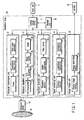
- FIG. 1 is a block diagram showing the arrangement of an ultrasonic diagnostic apparatus 1 according to this embodiment.
- the ultrasonic diagnostic apparatus 1 comprises an ultrasonic probe 10, storage unit 30, input unit 7, monitor 25, and apparatus body 50.
- the ultrasonic probe 10 includes a plurality of ultrasonic transducers which generate ultrasonic waves at a predetermined timing on the basis of a driving signal from an ultrasonic transmission unit 2 and convert reflected waves from a subject into electrical signals, matching layers provided for the ultrasonic transducers, backing members which prevent ultrasonic waves from propagating backward from the ultrasonic transducers, and the like.
- the transmitted ultrasonic waves are sequentially reflected by a discontinuity surface of acoustic impedance of internal body tissue, and are received as an echo signal by the ultrasonic probe 10.
- the amplitude of this echo signal depends on an acoustic impedance difference on the discontinuity surface by which the echo signal is reflected.
- the echo produced when an ultrasonic pulse is reflected by the surface of a moving blood flow, cardiac wall, or the like is subjected to a frequency shift depending on the speed component of the moving body in the ultrasonic transmission direction due to a Doppler effect.
- the ultrasonic probe 10 is formed as follows.
- ultrasonic transducer blocks BL each having a plurality of ultrasonic transducers (e.g., 12 elements x 48 elements) are formed by cutting a plurality of (e.g., three) blocks made of a ceramic piezoelectric material. These blocks are then bonded to each other in the array direction of ultrasonic transducers through adhesive layers.
- the storage unit 30 stores images obtained by past imaging operation, images captured by this apparatus through a network and detachable storage media, a dedicated program for the execution of a predetermined imaging sequence, and the like.
- the storage unit 30 also stores, for each probe, the spatial position of each ultrasonic transducer from a reference position set in consideration of an edge transducer gap and information (e.g., a predetermined formula or a correspondence table, which information will be referred to as "delay time/weighting coefficient acquisition information" hereinafter) for the acquisition of a delay time and weighting coefficient for each ultrasonic transducer on the basis of the spatial position of each ultrasonic transducer.
- the storage unit 30 stores, for each probe, a delay time and weighting coefficient for each ultrasonic transducer acquired on the basis of the spatial position of each ultrasonic transducer which is set in consideration of each edge transducer gap, as needed.
- the input unit 7 includes various kinds of switches and buttons, a trackball, a mouse, a keyboard, and the like which are connected to the apparatus body 50 of the ultrasonic diagnostic apparatus 1 to input various kinds of instructions and conditions, an instruction to set a region of interest (ROI), various kinds of image quality condition setting instructions, and the like from the operator to the apparatus body. For example, when the operator operates a predetermined button of the input unit 7, delay time/weighting coefficient optimization processing (to be described later) or displaying of the result obtained by the processing in a predetermined form is executed.
- the monitor 25 displays morphological information in the living body or blood flow information as an image on the basis of a video signal received from the apparatus body 50.
- the image or the like displayed on the monitor 25 is stored in a storage unit in the apparatus body 50 in response to predetermined operation with the input unit 7 or the like.
- the apparatus body 50 comprises the ultrasonic transmission unit 2 which performs transmission control on ultrasonic waves transmitted from the ultrasonic probe 10, an ultrasonic reception unit 3 which performs preprocessing for an echo signal received by the ultrasonic probe 10, a harmonic detection unit 4 which detects a harmonic component from the echo signal having undergone the preprocessing, a signal processing unit 5 which generates image data upon performing predetermined signal processing for the detected harmonic component, an image display unit 8 which generates and displays an ultrasonic image on the basis of the image data, and a control circuit (CPU) 6.
- the ultrasonic transmission unit 2 which performs transmission control on ultrasonic waves transmitted from the ultrasonic probe 10
- an ultrasonic reception unit 3 which performs preprocessing for an echo signal received by the ultrasonic probe 10
- a harmonic detection unit 4 which detects a harmonic component from the echo signal having undergone the preprocessing
- a signal processing unit 5 which generates image data upon performing predetermined signal processing for the detected harmonic component
- an image display unit 8 which generates and displays an ultra
- the ultrasonic transmission unit 2 comprises a rate pulse generator 11, transmission delay circuit 12, and pulser 13.
- the rate pulse generator 11 generates a rate pulse which determines the cycle period (rate period) of ultrasonic pulses to be emitted into the subject, and supplies the rate pulse to the transmission delay circuit 12.
- the transmission delay circuit 12 comprises independent delay circuits of M channels equal in number to the ultrasonic transducers used for transmission.
- the transmission delay circuit 12 gives the received rate pulse a focusing delay time for focusing ultrasonic pulses to a predetermined depth and a deflection delay time for transmitting the ultrasonic pulses in a predetermined direction, and supplies the resultant rate pulse to the pulser 13.
- the pulser 13 includes independent driving circuits of the M channels equal in number to the delay circuits of the transmission delay circuit 12.
- the ultrasonic transducers mounted on the ultrasonic probe 10 are driven to emit ultrasonic pulses into the subject by applying driving signals generated by the respective driving circuits to the respective ultrasonic transducers.
- the transmission delay circuit 12 of the ultrasonic transmission unit 2 combines the focusing delay time and deflection delay time which are optimized by delay time/weighting coefficient optimization processing (to be described later) to give a delay time to the rate pulse.
- the ultrasonic reception unit 3 comprises a preamplifier 14, A/D converter 15, beam former 16, and adder 28.
- the preamplifier 14 is designed to amplify small signals converted into electrical echo signals by the ultrasonic transducers to ensure a sufficient S/N ratio.
- the fundamental components and harmonic components of the echo signals amplified to a predetermined magnitude by the preamplifier 14 are converted into digital signals by the A/D converter 15, and the digital signals are sent to the beam former 16.
- the beam former 16 gives each echo signal converted into a digital signal a focusing delay time for focusing each reflected ultrasonic wave from a predetermined depth and a deflection delay time for scanning the subject while sequentially changing the reception directivity of each reflected ultrasonic wave.
- the adder 28 performs phased addition of the outputs from the beam former 16 (addition of the echo signals obtained from a predetermined direction upon phasing).
- the beam former 16 of the ultrasonic reception unit 3 performs beam forming by using at least one of the focusing delay time and the deflection delay time which are optimized by delay time/weighting coefficient optimization processing (to be described later).
- the adder 28 of the ultrasonic reception unit 3 performs addition processing in accordance with a control signal from the control circuit 6 in delay time/weighting coefficient optimization processing (to be described later).
- the harmonic detection unit 4 performs processing associated with the phase-in version method, and comprises a waveform memory 17, adder-subtracter 18, and filter circuit 19.
- the waveform memory 17 temporarily stores echo signals obtained by the first transmission/reception in a predetermined direction.
- the filter circuit 19 is a filter which reduces fundamental components which cannot be erased by the phase-in version method due to the movement of an organ and the movement of the body.
- the signal processing unit 5 comprises an envelope detector 20, logarithmic transformer 21, and persistence transformer 22.
- the envelope detector 20 performs envelope detection computation for an input digital signal to detect its envelope.
- the logarithmic transformer 21 comprises a lookup table which logarithmically transforms an input value and outputs the resultant data.
- the logarithmic transformer 21 logarithmically transforms the amplitude of an echo signal to relatively enhance a weak signal.
- the persistence transformer temporarily stores scanning lines corresponding to several frames, and performs processing of averaging luminance changes.
- the image display unit 8 comprises a display image memory 23 and a conversion circuit 24.
- the display image memory 23 combines image data supplied from the signal processing unit 5 and accessory data such as characters and numerals associated with the image data, and temporarily stores the resultant data.
- the display image memory 23 temporarily stores image data obtained by combining a normal mode image and a puncture mode image in a predetermined form.
- the stored image data and accessory data are subjected to D/A conversion and TV format conversion in the conversion circuit 24, and the resultant image is displayed on the monitor 25.
- the control circuit 6 reads out transmission/reception conditions and a dedicated program stored in the storage unit 30 on the basis of instructions of mode selection, transmission start/end, and the like input from the input unit 7, and statically or dynamically controls each unit and the overall system in accordance with them.
- the control circuit 6 reads out a dedicated program for implementing the delay time/weighting coefficient optimization function (to be described later) from the storage unit 30, loads the program in a predetermined memory, and executes control on each unit in accordance with the program.
- a dedicated program for implementing the delay time/weighting coefficient optimization function to be described later
- the delay time/weighting coefficient optimization function of the ultrasonic diagnostic apparatus 1 will be described next. This function is used to accurately grasp the spatial position of each ultrasonic transducer for each probe and execute ultrasonic transmission/reception by using the delay time/weighting coefficient calculated on the basis of the spatial position of each ultrasonic transducer, thereby realizing a suitable acoustic field in consideration of the influence of each edge transducer gap and the acoustic characteristics of each edge transducer.
- the delay time optimized by this function is a delay pattern for beam forming (to be executed at the time of transmission or reception).
- the weighting coefficient optimized by this function indicates the weighting coefficient of an aperture function used in echo signal addition processing.
- this optimization function can be implemented by installing software programs for executing processing associated with this function in an existing ultrasonic diagnostic apparatus or a computer such as a workstation and loading the programs in a memory as well as being implemented by a hardware arrangement.
- the programs which can cause the computer to execute the corresponding techniques can be distributed by being stored in recording media such as magnetic disks (floppy (registered trademark) disks, hard disks, and the like), optical disks (CD-ROMs, DVDs, and the like), and semiconductor memories.
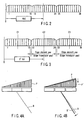
- FIG. 2 is a view for explaining a conventional delay time/weighting coefficient calculation technique.
- an ultrasonic transducer array is assumed to have an ideal structure without any edge transducer gap due to the connection layers which connect the ultrasonic transducer blocks to each other, a coordinate axis is set with, for example, a reference position O being an origin, and a spatial position x(n) ( n is a transducer number) of each element is defined on the basis of the width of each element, an array pitch, and the like.
- a delay time and a weighting coefficient are determined by predetermined formulas T(x(n)) and W(x(n)) defined with reference to the above ideal structure.
- This delay time/weighting coefficient optimization function serves to accurately grasp the spatial position of each ultrasonic transducer for each probe and execute ultrasonic transmission/reception by using the delay time and weighting coefficient for each transducer calculated on the basis of the spatial position of each transducer.
- FIG. 3 is a view for explaining a delay time/weighting coefficient calculation technique according to this function.
- a coordinate axis with the reference position O being an origin is set, and a spatial position x'(n) of each element is defined in consideration of the edge transducer gaps.
- a delay time and a weighting coefficient are determined by predetermined formulas T(x'(n)) and W(x'(n)) defined in consideration of the edge transducer gaps.
- the reference positions (central positions C1, C2, and C3 in the example shown in FIG. 3 ) of ultrasonic blocks BL1, BL2, and BL3 are measured.
- the spatial position x'(n) of each ultrasonic transducer is determined in accordance with the distance from each central position.
- the central positions C1, C2, and C3 of the respective ultrasonic blocks are measured in consideration of the thicknesses of connection layers D1 and D2, the spatial position x'(n) of each ultrasonic transducer can be accurately grasped.
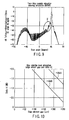
- a delay time and a weighting coefficient are accurately defined on the basis of the spatial position of each ultrasonic transducer. Take a transmission/reception delay time for example, if a conventional delay pattern P with no consideration given to edge transducer gaps and a beam B based on this pattern are those shown in FIG. 4A , this function can correct them into a deflection delay pattern P' and a beam B' based on this pattern as shown in FIG. 4B . This makes it possible to eliminate errors due to the edge transducer gaps and realize a suitable acoustic field which improves the deflection angle accuracy and includes little sidelobes.
- a delay time and a weighting coefficient are defined by predetermined formulas T(x(n)), W(x(n)), T(x',(n)), and W(x'(n)).
- the present invention is not limited to this, and the technical idea of the present invention can be applied to any arrangement as long as each ultrasonic transducer is identified on the basis of an accurate spatial position in consideration of edge transducer gaps, and a delay time and a weighting coefficient are defined for each identified element. Therefore, a delay time and a weighting coefficient for each element may be obtained by using a table which associates the spatial position of each transducer, obtained in consideration of edge transducer gaps, with a delay time and a weighting coefficient.
- each ultrasonic block BLn (n is a natural number) is not limited to a central position Cn of each block. That is, the reference position may be any position as long as the position of each element of each ultrasonic block can be determined in consideration of the thickness of a connection layer Dn.
- This embodiment has exemplified the case wherein the ultrasonic blocks BLn are one-dimensionally (in the array direction) connected through the connection layers Dn.
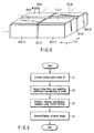
- the present invention is not limited to this, and the technique of this embodiment can also be applied to a case wherein ultrasonic blocks BL(n, m) ( n and m are both natural numbers) are two-dimensional connected to each other through connection layers Dn and Dm, as shown in, for example, FIG. 5 .
- central positions C(1, 1),..., C(n, m) of ultrasonic blocks BL(1, 1), ..., BL(n, m) are measured.
- a spatial position x'(n, m) of each ultrasonic transducer is determined in accordance with the distance from each central position.
- the spatial position x'(n, m) of each ultrasonic transducer can be accurately grasped.
- Calculation of delay times and weighting coefficients with consideration given to the above edge transducer gaps is executed according to a predetermined formula, rule, or the like on the basis of the spatial positions of the respective ultrasonic transducers.
- the position of each ultrasonic transducer which is used in this case can be measured by, for example, one of the methods according to the first to third embodiments to be described below.
- an array shape is measured by using a microscope or the like, and offset values and variations of ultrasonic transducer block intervals are obtained and calculated as statistics for each production lot of ultrasonic transducer blocks.
- Predetermined correction is then performed by using software for the system on the basis of the obtained offset values, and the unified spatial position of each ultrasonic transducer is obtained for each production lot. According to this technique, the spatial position of each ultrasonic transducer can be acquired relatively easily in consideration of the influences of edge transducer gaps.
- An array shape (ultrasonic transducer block interval or the like) is measured for each ultrasonic probe before a manufactured lens is bonded.
- the measured value is input to a predetermined correction table incorporated in advance in an ultrasonic diagnostic apparatus 1, and correction is performed for each probe by using each piece of probe information.
- This technique can acquire the spatial position of each ultrasonic transducer in consideration of edge transducer gaps more accurately than the technique according to the first embodiment and more easily than the technique according to the third embodiment.
- Each manufactured probe is placed in a water bath, and an acoustic field is measured. Parameters are operated and optimized until deflection angles and sidelobes fall within specified values, and the optimal values are input to a predetermined correction table incorporated in the apparatus in advance, thereby performing correction for each probe. For example, a sidelobe originating from an adhesive layer between ultrasonic transducer blocks has a shape with a certain tendency. The influence of an edge transducer gap can be corrected by inputting optimal values so as to reduce such a tendency. This technique can acquire the spatial position of each ultrasonic transducer more accurately than the techniques according to the first and second embodiments.
- an ultrasonic probe 10 having an arrangement in which ultrasonic blocks BLn are bonded to each other through adhesive layers Dn, a problem arises in terms of the acoustic characteristics of edge transducers bonded to the adhesive layers.
- a weighting coefficient for attenuating an echo signal from each edge transducer is set, and addition processing is performed by using it to reduce a sidelobe due to the acoustic characteristics of each edge transducer (apodization).
- apodization may be executed for a signal at the time of transmission as well as a signal at the time of reception. That is, a transmission voltage is set with a weight that reduces transmission ultrasonic waves and is applied to each edge transducer. This makes it possible to transmit a beam with a reduced sidelobe originating from the acoustic characteristics of each edge transducer.
- FIG. 6 is a flowchart showing the flow of each processing executed in ultrasonic transmission/reception based on the delay time/weighting coefficient optimization function.
- a control circuit 6 recognizes the ID of the connected ultrasonic probe 10 (step S1), and acquires a delay time and weighting coefficient for each ultrasonic transducer of the ultrasonic probe (i.e., T(x'(n)) and W(x'(n)) set in consideration of each edge transducer gap) from a storage unit 30 (step S2).
- a weighting coefficient is determined for each edge transducer to reduce a sidelobe originating from its acoustic characteristics.
- this delay time and weighting coefficient are calculated in advance by using the spatial position information and delay time/weighting coefficient acquisition information of each ultrasonic transducer of the ultrasonic probe which are stored in the storage unit 30.
- the present invention is not limited to this. For example, every time an ultrasonic probe is connected to the apparatus body 50, a delay time and a weighting coefficient may be calculated by using the spatial position information and delay time/weighting coefficient information of each ultrasonic transducer of the ultrasonic probe which are stored in the storage unit 30.
- Ultrasonic transmission/reception is performed on the basis of the acquired delay time/weighting coefficient information (step S3).
- An ultrasonic image is then generated on the basis of acquired echo signals, and is displayed in a predetermined form (step S4).
- the position of each ultrasonic transducer is accurately specified in consideration of each edge transducer gap, and a delay time/weighting coefficient for each transducer is determined in ultrasonic transmission/reception on the basis of the specified position. For example, a reference position of each ultrasonic block is measured, and a spatial position x'(n) of each ultrasonic transducer is determined in accordance with the distance from each reference position. Since a delay time and a weighting coefficient are determined in accordance with the position of each ultrasonic transducer, accurate delay times and weighting coefficients can be determined in consideration of the thickness of each adhesive layer as compared with the prior art in which delay times and weighting coefficients are determined without any consideration to edge transducer gaps.
- a weighting coefficient matching the characteristics of each transducer can be set by specifying each edge transducer on the basis of accurate spatial positions and selecting a weighting coefficient corresponding to a deterioration in the sensitivity of each edge transducer. This makes it possible to realize a suitable acoustic field which realizes high deflection angle accuracy and can reduce sidelobes and the like as compared with the prior art.
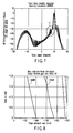
- FIG. 7 is a graph showing the spectrum distribution of echo signals obtained by ultrasonic transmission/reception using delay times and weighting coefficients according to the prior art (i.e., those determined by a technique without any consideration to edge transducer gaps).
- FIG. 8 is a graph showing the distribution of sidelobes which appear in ultrasonic transmission/reception using delay times and weighting coefficient according to the prior art.
- FIG. 9 is a graph showing the spectrum distribution of echo signals obtained by ultrasonic transmission/reception using delay times and weighting coefficients determined by this delay time/weighting coefficient optimization function.
- FIG. 10 is a graph showing the distribution of sidelobes which appear in ultrasonic transmission/reception using delay times and weighting coefficient determined by the delay time/weighting coefficient optimization function.
- FIGS. 7 and 9 A comparison between FIGS. 7 and 9 reveals that the size of a sidelobe S' is smaller than that of a sidelobe S.
- FIGS. 8 and 10 a comparison between FIGS. 8 and 10 reveals that in ultrasonic transmission/reception executed in this apparatus, the occurrence of sidelobes is more suppressed, and the resolution improves.
- This technique has the effect of solving the problem that the main lobe is located inside more than actually due to the shadows of the edge transducer gaps, in addition to the sidelobe reducing effect.
- edge transducers bonded to the adhesive layers are reduced by executing apodization associated with the edge transducers at least at the time of transmission or reception.
- apodization associated with the edge transducers at least at the time of transmission or reception.
- a program which implements this delay time/weighting coefficient optimization function and the spatial position of each ultrasonic transducer obtained in consideration of each edge transducer gap are installed in an existing apparatus, and the apparatus is activated to implement the delay time/weighting coefficient optimization function. Therefore, this function can be implemented at a relatively low cost and with ease.
- the present invention is not limited to the above embodiment, and can be embodied in the execution stage by modifying constituent elements within the spirit and scope of the invention. For example, the following are specific modifications.
Description
- The present invention relates to the optimization of beam deflection in ultrasonic transmission/reception using a two-dimensional ultrasonic probe having, for example, ultrasonic transducers arranged in a two-dimensional matrix, a delay time for beam convergence, a weighting coefficient used in echo signal addition processing, and the like.
- An ultrasonic diagnostic apparatus is a medical image device which noninvasively obtains a tomogram of a soft tissue in a living body from the body surface by an ultrasonic pulse reflection method. This ultrasonic diagnostic apparatus has advantages of being smaller in size, more inexpensive, and safer because of no exposure to X-rays and the like than other medical image devices, and of being capable of blood flow imaging, and hence is widely used in a cardiac department, abdominal department, urological department, obsterics and gynecology, and the like.
- In recent ultrasonic imaging apparatuses, a real-time three-dimensional display function (three-dimensional real-time display function) has been put into practice. Techniques for this function include a technique (mechanical 4D scanning method) of using a mechanical 3D scanner which scans a three-dimensional area of a subject by mechanically scanning an electronic scanning type one-dimensional array transducer in a direction perpendicular to a scanning surface and a technique (to be referred to as a real-time 3D scanning method hereinafter) of realizing scanning on a three-dimensional area of a subject by electronic scanning operation using a two-dimensional ultrasonic probe having a two-dimensional array of transducers (see, for example, Jpn. Pat. Appln. KOKAI Publication Nos.
6-169921 9-313487 - The real-time 3D scanning method, in particular, has been rapidly popularized together with the introduction of a two-dimensional ultrasonic probe. As shown in
FIG. 11 , a two-dimensional ultrasonic probe used in this real-time 3D scanning method, which has ultrasonic transducers arranged in a two-dimensional matrix (e.g., 36 elements x 48 elements = 1728 elements), is formed by cutting a plurality of (e.g., three) blocks made of a ceramic piezoelectric material or the like (into 12 elements x 48 elements each) so as to form ultrasonic transducer blocks BL having a plurality of ultrasonic transducers, and bonding the blocks BL to each other through adhesive layers as shown inFIG. 12 . Note that a plurality of ultrasonic transducer blocks BL are bonded to each other through adhesive layers in this manner because it is difficult to cut one ceramic piezoelectric material block into, for example, 1782 elements by using any one of the current dicing techniques. - For example, the following problems arise in the conventional ultrasonic diagnostic apparatuses.
-
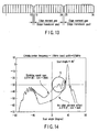
FIG. 13 is an enlarged view of the inside of the circle shown inFIG. 12 , which shows an edge of each ultrasonic transducer block on the ultrasonic wave application side. As has been described above, the respective ultrasonic transducer blocks are bonded to each other through adhesive layers (not shown). As shown inFIG. 13 , therefore, the ultrasonic transducer at one or two ends of each ultrasonic transducer block (inFIG. 13 , the 12th, 13th, 24th, and 25th ultrasonic transducers to be referred to as "edge ultrasonic transducers" hereinafter) are bonded to the adhesive layers. For this reason, each edge ultrasonic transducer is subjected to the influence of bonding (e.g., changes in shape and the like), and has vibration characteristics (i.e., acoustic characteristics) different from those of the other type (which is not used for bonding) of ultrasonic transducers. However, the conventional system gives no consideration of the characteristic difference between edge ultrasonic transducers and the other type of ultrasonic transducers due to this bonding. - In addition, there are gaps (edge transducer gaps) due to the presence of the adhesive layers between edges of the ultrasonic transducer blocks. However, calculation of delay times and the like in ultrasonic transmission/reception in the prior art gives no consideration to such edge transducer gaps. This may therefore be a factor that causes a corresponding error. For example, this causes a sidelobe S like that shown in
FIG. 14 . -
DE 103 36 101 A1 discloses an ultrasound transmit pulser with receive interconnection and method of use.US 2001/015592 A1 discloses a medical diagnostic ultrasound transducer comprising a plurality of piezomaterial bodies that are merged together to form a larger piezomaterial body.US 5 920 523 A discloses two-dimensional acoustic array comprising a plurality of transducer segments. - The present invention has been made in consideration of the above situation, and has as its object to provide an ultrasonic transmission/reception condition optimization method, and an ultrasonic diagnostic apparatus which can realize suitable acoustic characteristics as compared with the prior art by executing ultrasonic transmission/reception in consideration of edge transducer gaps and the characteristics of edge transducers.
- This is achieved by the present invention as defined in
claims 1 and 9. Further advantageous embo- diments are set forth in the subclaims. - The invention can be more fully understood from the following detailed description when taken in conjunction with the accompanying drawings, in which:
-
FIG. 1 is a block diagram showing the arrangement of an ultrasonicdiagnostic apparatus 1 according to this embodiment; -
FIG. 2 is a view for explaining a delay time/weighting coefficient calculation technique in a conventional ultrasonic diagnostic apparatus; -
FIG. 3 is a view for explaining a delay time/weighting coefficient calculation technique associated with a delay time/weighting coefficient optimization function according to this embodiment; -
FIG. 4A is a view for explaining an example of the effect obtained by this delay time/weighting coefficient optimization function; -
FIG. 4B is a view for explaining an example of the effect obtained by this delay time/weighting coefficient optimization function; -
FIG. 5 is a perspective view for explaining an example in which ultrasonic transducer blocks BL(n, m) are connected and arranged in the form of a two-dimensional matrix through connection layers Dn and Dm; -
FIG. 6 is a flowchart showing the flow of each processing executed in ultrasonic transmission/reception based on the delay time/weighting coefficient optimization function; -
FIG. 7 is a graph showing the spectrum distribution of echo signals obtained by ultrasonic transmission/reception using delay times and weighting coefficients according to the prior art (i.e., without any consideration to edge transducer gaps); -
FIG. 8 is a graph showing the distribution of sidelobes which appear in ultrasonic transmission/reception using delay times and weighting coefficients according to the prior art; -
FIG. 9 is a graph showing the spectrum distribution of echo signals obtained by ultrasonic transmission/reception using delay times and weighting coefficients determined by this delay time/weighting coefficient optimization function; -
FIG. 10 is a graph showing the distribution of sidelobes which appear in ultrasonic transmission/reception using delay times and weighting coefficients determined by this delay time/weighting coefficient optimization function; -
FIG. 11 is a view for explaining the ultrasonic transducer array of an ultrasonic probe; -
FIG. 12 is a view for explaining the ultrasonic transducer array of the ultrasonic probe; -
FIG. 13 is a view for explaining the ultrasonic transducer array of the ultrasonic probe; and -
FIG. 14 is a graph showing the spectrum distribution of transmission ultrasonic waves to explain problems in a conventional ultrasonic diagnostic apparatus. - An embodiment of the present invention will be described below with reference to the views of the accompanying drawing. Note that the same reference numerals denote constituent elements having substantially the same functions and arrangements, and a repetitive description will be made only when required.
-
FIG. 1 is a block diagram showing the arrangement of an ultrasonicdiagnostic apparatus 1 according to this embodiment. As shown inFIG. 1 , the ultrasonicdiagnostic apparatus 1 comprises anultrasonic probe 10,storage unit 30,input unit 7,monitor 25, andapparatus body 50. - The
ultrasonic probe 10 includes a plurality of ultrasonic transducers which generate ultrasonic waves at a predetermined timing on the basis of a driving signal from anultrasonic transmission unit 2 and convert reflected waves from a subject into electrical signals, matching layers provided for the ultrasonic transducers, backing members which prevent ultrasonic waves from propagating backward from the ultrasonic transducers, and the like. When ultrasonic waves are transmitted from theultrasonic probe 10 to a subject P, the transmitted ultrasonic waves are sequentially reflected by a discontinuity surface of acoustic impedance of internal body tissue, and are received as an echo signal by theultrasonic probe 10. The amplitude of this echo signal depends on an acoustic impedance difference on the discontinuity surface by which the echo signal is reflected. The echo produced when an ultrasonic pulse is reflected by the surface of a moving blood flow, cardiac wall, or the like is subjected to a frequency shift depending on the speed component of the moving body in the ultrasonic transmission direction due to a Doppler effect. - For the sake of a concrete description, assume that the
ultrasonic probe 10 is a two-dimensional ultrasonic probe having ultrasonic transducers arranged in a two-dimensional matrix (e.g., 36 elements x 48 elements = 1728 elements). Theultrasonic probe 10 is formed as follows. For example, ultrasonic transducer blocks BL each having a plurality of ultrasonic transducers (e.g., 12 elements x 48 elements) are formed by cutting a plurality of (e.g., three) blocks made of a ceramic piezoelectric material. These blocks are then bonded to each other in the array direction of ultrasonic transducers through adhesive layers. - The
storage unit 30 stores images obtained by past imaging operation, images captured by this apparatus through a network and detachable storage media, a dedicated program for the execution of a predetermined imaging sequence, and the like. - The
storage unit 30 also stores, for each probe, the spatial position of each ultrasonic transducer from a reference position set in consideration of an edge transducer gap and information (e.g., a predetermined formula or a correspondence table, which information will be referred to as "delay time/weighting coefficient acquisition information" hereinafter) for the acquisition of a delay time and weighting coefficient for each ultrasonic transducer on the basis of the spatial position of each ultrasonic transducer. In addition, thestorage unit 30 stores, for each probe, a delay time and weighting coefficient for each ultrasonic transducer acquired on the basis of the spatial position of each ultrasonic transducer which is set in consideration of each edge transducer gap, as needed. - The
input unit 7 includes various kinds of switches and buttons, a trackball, a mouse, a keyboard, and the like which are connected to theapparatus body 50 of the ultrasonicdiagnostic apparatus 1 to input various kinds of instructions and conditions, an instruction to set a region of interest (ROI), various kinds of image quality condition setting instructions, and the like from the operator to the apparatus body. For example, when the operator operates a predetermined button of theinput unit 7, delay time/weighting coefficient optimization processing (to be described later) or displaying of the result obtained by the processing in a predetermined form is executed. - The
monitor 25 displays morphological information in the living body or blood flow information as an image on the basis of a video signal received from theapparatus body 50. The image or the like displayed on themonitor 25 is stored in a storage unit in theapparatus body 50 in response to predetermined operation with theinput unit 7 or the like. - The
apparatus body 50 comprises theultrasonic transmission unit 2 which performs transmission control on ultrasonic waves transmitted from theultrasonic probe 10, anultrasonic reception unit 3 which performs preprocessing for an echo signal received by theultrasonic probe 10, a harmonic detection unit 4 which detects a harmonic component from the echo signal having undergone the preprocessing, a signal processing unit 5 which generates image data upon performing predetermined signal processing for the detected harmonic component, an image display unit 8 which generates and displays an ultrasonic image on the basis of the image data, and a control circuit (CPU) 6. - The
ultrasonic transmission unit 2 comprises arate pulse generator 11,transmission delay circuit 12, andpulser 13. Therate pulse generator 11 generates a rate pulse which determines the cycle period (rate period) of ultrasonic pulses to be emitted into the subject, and supplies the rate pulse to thetransmission delay circuit 12. Thetransmission delay circuit 12 comprises independent delay circuits of M channels equal in number to the ultrasonic transducers used for transmission. Thetransmission delay circuit 12 gives the received rate pulse a focusing delay time for focusing ultrasonic pulses to a predetermined depth and a deflection delay time for transmitting the ultrasonic pulses in a predetermined direction, and supplies the resultant rate pulse to thepulser 13. Thepulser 13 includes independent driving circuits of the M channels equal in number to the delay circuits of thetransmission delay circuit 12. The ultrasonic transducers mounted on theultrasonic probe 10 are driven to emit ultrasonic pulses into the subject by applying driving signals generated by the respective driving circuits to the respective ultrasonic transducers. - Note that the
transmission delay circuit 12 of theultrasonic transmission unit 2 combines the focusing delay time and deflection delay time which are optimized by delay time/weighting coefficient optimization processing (to be described later) to give a delay time to the rate pulse. - The
ultrasonic reception unit 3 comprises apreamplifier 14, A/D converter 15, beam former 16, andadder 28. Thepreamplifier 14 is designed to amplify small signals converted into electrical echo signals by the ultrasonic transducers to ensure a sufficient S/N ratio. The fundamental components and harmonic components of the echo signals amplified to a predetermined magnitude by thepreamplifier 14 are converted into digital signals by the A/D converter 15, and the digital signals are sent to the beam former 16. The beam former 16 gives each echo signal converted into a digital signal a focusing delay time for focusing each reflected ultrasonic wave from a predetermined depth and a deflection delay time for scanning the subject while sequentially changing the reception directivity of each reflected ultrasonic wave. Theadder 28 performs phased addition of the outputs from the beam former 16 (addition of the echo signals obtained from a predetermined direction upon phasing). - Note that the beam former 16 of the
ultrasonic reception unit 3 performs beam forming by using at least one of the focusing delay time and the deflection delay time which are optimized by delay time/weighting coefficient optimization processing (to be described later). Theadder 28 of theultrasonic reception unit 3 performs addition processing in accordance with a control signal from thecontrol circuit 6 in delay time/weighting coefficient optimization processing (to be described later). - The harmonic detection unit 4 performs processing associated with the phase-in version method, and comprises a
waveform memory 17, adder-subtracter 18, andfilter circuit 19. Thewaveform memory 17 temporarily stores echo signals obtained by the first transmission/reception in a predetermined direction. The adder-subtracter 18 adds or subtracts echo signals obtained by second to nth (n is a natural number of two or more; n = 4 in this case) transmission/reception in the predetermined direction and the echo signals stored in thewaveform memory 17. Thefilter circuit 19 is a filter which reduces fundamental components which cannot be erased by the phase-in version method due to the movement of an organ and the movement of the body. - The signal processing unit 5 comprises an
envelope detector 20,logarithmic transformer 21, andpersistence transformer 22. Theenvelope detector 20 performs envelope detection computation for an input digital signal to detect its envelope. Thelogarithmic transformer 21 comprises a lookup table which logarithmically transforms an input value and outputs the resultant data. Thelogarithmic transformer 21 logarithmically transforms the amplitude of an echo signal to relatively enhance a weak signal. The persistence transformer temporarily stores scanning lines corresponding to several frames, and performs processing of averaging luminance changes. - The image display unit 8 comprises a
display image memory 23 and aconversion circuit 24. Thedisplay image memory 23 combines image data supplied from the signal processing unit 5 and accessory data such as characters and numerals associated with the image data, and temporarily stores the resultant data. Thedisplay image memory 23 temporarily stores image data obtained by combining a normal mode image and a puncture mode image in a predetermined form. The stored image data and accessory data are subjected to D/A conversion and TV format conversion in theconversion circuit 24, and the resultant image is displayed on themonitor 25. - The
control circuit 6 reads out transmission/reception conditions and a dedicated program stored in thestorage unit 30 on the basis of instructions of mode selection, transmission start/end, and the like input from theinput unit 7, and statically or dynamically controls each unit and the overall system in accordance with them. In this embodiment, in particular, thecontrol circuit 6 reads out a dedicated program for implementing the delay time/weighting coefficient optimization function (to be described later) from thestorage unit 30, loads the program in a predetermined memory, and executes control on each unit in accordance with the program. (Ultrasonic Transmission/Reception Condition (Delay Time/Weighting Coefficient) Optimization Function) - The delay time/weighting coefficient optimization function of the ultrasonic
diagnostic apparatus 1 will be described next. This function is used to accurately grasp the spatial position of each ultrasonic transducer for each probe and execute ultrasonic transmission/reception by using the delay time/weighting coefficient calculated on the basis of the spatial position of each ultrasonic transducer, thereby realizing a suitable acoustic field in consideration of the influence of each edge transducer gap and the acoustic characteristics of each edge transducer. - Note that the delay time optimized by this function is a delay pattern for beam forming (to be executed at the time of transmission or reception). In addition, the weighting coefficient optimized by this function indicates the weighting coefficient of an aperture function used in echo signal addition processing.
- In addition, this optimization function can be implemented by installing software programs for executing processing associated with this function in an existing ultrasonic diagnostic apparatus or a computer such as a workstation and loading the programs in a memory as well as being implemented by a hardware arrangement. In this case, the programs which can cause the computer to execute the corresponding techniques can be distributed by being stored in recording media such as magnetic disks (floppy (registered trademark) disks, hard disks, and the like), optical disks (CD-ROMs, DVDs, and the like), and semiconductor memories.
-
FIG. 2 is a view for explaining a conventional delay time/weighting coefficient calculation technique. As shown inFIG. 2 , in the conventional technique, an ultrasonic transducer array is assumed to have an ideal structure without any edge transducer gap due to the connection layers which connect the ultrasonic transducer blocks to each other, a coordinate axis is set with, for example, a reference position O being an origin, and a spatial position x(n) (n is a transducer number) of each element is defined on the basis of the width of each element, an array pitch, and the like. In addition, a delay time and a weighting coefficient are determined by predetermined formulas T(x(n)) and W(x(n)) defined with reference to the above ideal structure. - In an actual ultrasonic transducer array, however, there are edge transducer gaps due to the connection layers which connect the ultrasonic transducer blocks to each other, and hence the positions of the respective elements are influenced by the edge transducer gaps (see
FIG. 3 ). For this reason, the spatial position x(n) of each element which is defined by the conventional technique is not accurate, and hence the delay time and weighting coefficient which are determined by using the position x(n) and predetermined formulas T(x(n)) and W(x(n)) also contain errors due to the edge transducer gaps and become factors that produce an acoustic field which degrades a low deflection angle accuracy and includes many sidelobes. - This delay time/weighting coefficient optimization function serves to accurately grasp the spatial position of each ultrasonic transducer for each probe and execute ultrasonic transmission/reception by using the delay time and weighting coefficient for each transducer calculated on the basis of the spatial position of each transducer.
-
FIG. 3 is a view for explaining a delay time/weighting coefficient calculation technique according to this function. According to this function, for example, a coordinate axis with the reference position O being an origin is set, and a spatial position x'(n) of each element is defined in consideration of the edge transducer gaps. In addition, a delay time and a weighting coefficient are determined by predetermined formulas T(x'(n)) and W(x'(n)) defined in consideration of the edge transducer gaps. - First of all, the reference positions (central positions C1, C2, and C3 in the example shown in
FIG. 3 ) of ultrasonic blocks BL1, BL2, and BL3 are measured. In each ultrasonic block, the spatial position x'(n) of each ultrasonic transducer is determined in accordance with the distance from each central position. At this time, since the central positions C1, C2, and C3 of the respective ultrasonic blocks are measured in consideration of the thicknesses of connection layers D1 and D2, the spatial position x'(n) of each ultrasonic transducer can be accurately grasped. - In addition, a delay time and a weighting coefficient are accurately defined on the basis of the spatial position of each ultrasonic transducer. Take a transmission/reception delay time for example, if a conventional delay pattern P with no consideration given to edge transducer gaps and a beam B based on this pattern are those shown in
FIG. 4A , this function can correct them into a deflection delay pattern P' and a beam B' based on this pattern as shown inFIG. 4B . This makes it possible to eliminate errors due to the edge transducer gaps and realize a suitable acoustic field which improves the deflection angle accuracy and includes little sidelobes. - In this embodiment, for the sake of descriptive convenience, a delay time and a weighting coefficient are defined by predetermined formulas T(x(n)), W(x(n)), T(x',(n)), and W(x'(n)). However, the present invention is not limited to this, and the technical idea of the present invention can be applied to any arrangement as long as each ultrasonic transducer is identified on the basis of an accurate spatial position in consideration of edge transducer gaps, and a delay time and a weighting coefficient are defined for each identified element. Therefore, a delay time and a weighting coefficient for each element may be obtained by using a table which associates the spatial position of each transducer, obtained in consideration of edge transducer gaps, with a delay time and a weighting coefficient.
- In addition, the reference position of each ultrasonic block BLn (n is a natural number) is not limited to a central position Cn of each block. That is, the reference position may be any position as long as the position of each element of each ultrasonic block can be determined in consideration of the thickness of a connection layer Dn.
- This embodiment has exemplified the case wherein the ultrasonic blocks BLn are one-dimensionally (in the array direction) connected through the connection layers Dn. However, the present invention is not limited to this, and the technique of this embodiment can also be applied to a case wherein ultrasonic blocks BL(n, m) (n and m are both natural numbers) are two-dimensional connected to each other through connection layers Dn and Dm, as shown in, for example,
FIG. 5 . In this case, central positions C(1, 1),..., C(n, m) of ultrasonic blocks BL(1, 1), ..., BL(n, m) are measured. In each ultrasonic block, then, a spatial position x'(n, m) of each ultrasonic transducer is determined in accordance with the distance from each central position. At this time, since the thicknesses of the connection layers Dn and Dm are taken into consideration in the measurement of the central position C(n, m) of each ultrasonic block, the spatial position x'(n, m) of each ultrasonic transducer can be accurately grasped. - Calculation of delay times and weighting coefficients with consideration given to the above edge transducer gaps is executed according to a predetermined formula, rule, or the like on the basis of the spatial positions of the respective ultrasonic transducers. The position of each ultrasonic transducer which is used in this case can be measured by, for example, one of the methods according to the first to third embodiments to be described below.
- Before acoustic lenses and the like are bonded, an array shape is measured by using a microscope or the like, and offset values and variations of ultrasonic transducer block intervals are obtained and calculated as statistics for each production lot of ultrasonic transducer blocks. Predetermined correction is then performed by using software for the system on the basis of the obtained offset values, and the unified spatial position of each ultrasonic transducer is obtained for each production lot. According to this technique, the spatial position of each ultrasonic transducer can be acquired relatively easily in consideration of the influences of edge transducer gaps.
- An array shape (ultrasonic transducer block interval or the like) is measured for each ultrasonic probe before a manufactured lens is bonded. The measured value is input to a predetermined correction table incorporated in advance in an ultrasonic
diagnostic apparatus 1, and correction is performed for each probe by using each piece of probe information. This technique can acquire the spatial position of each ultrasonic transducer in consideration of edge transducer gaps more accurately than the technique according to the first embodiment and more easily than the technique according to the third embodiment. - Each manufactured probe is placed in a water bath, and an acoustic field is measured. Parameters are operated and optimized until deflection angles and sidelobes fall within specified values, and the optimal values are input to a predetermined correction table incorporated in the apparatus in advance, thereby performing correction for each probe. For example, a sidelobe originating from an adhesive layer between ultrasonic transducer blocks has a shape with a certain tendency. The influence of an edge transducer gap can be corrected by inputting optimal values so as to reduce such a tendency. This technique can acquire the spatial position of each ultrasonic transducer more accurately than the techniques according to the first and second embodiments.
- In an
ultrasonic probe 10 having an arrangement in which ultrasonic blocks BLn are bonded to each other through adhesive layers Dn, a problem arises in terms of the acoustic characteristics of edge transducers bonded to the adhesive layers. In this ultrasonic diagnostic apparatus, a weighting coefficient for attenuating an echo signal from each edge transducer is set, and addition processing is performed by using it to reduce a sidelobe due to the acoustic characteristics of each edge transducer (apodization). - In addition, apodization may be executed for a signal at the time of transmission as well as a signal at the time of reception. That is, a transmission voltage is set with a weight that reduces transmission ultrasonic waves and is applied to each edge transducer. This makes it possible to transmit a beam with a reduced sidelobe originating from the acoustic characteristics of each edge transducer.
- Ultrasonic transmission/reception based on the delay time/weighting coefficient optimization function of an ultrasonic
diagnostic apparatus 1 will be described next. -
FIG. 6 is a flowchart showing the flow of each processing executed in ultrasonic transmission/reception based on the delay time/weighting coefficient optimization function. As shown inFIG. 6 , first of all, when theultrasonic probe 10 used for imaging is connected to anapparatus body 50, acontrol circuit 6 recognizes the ID of the connected ultrasonic probe 10 (step S1), and acquires a delay time and weighting coefficient for each ultrasonic transducer of the ultrasonic probe (i.e., T(x'(n)) and W(x'(n)) set in consideration of each edge transducer gap) from a storage unit 30 (step S2). In addition, a weighting coefficient is determined for each edge transducer to reduce a sidelobe originating from its acoustic characteristics. - Note that this delay time and weighting coefficient are calculated in advance by using the spatial position information and delay time/weighting coefficient acquisition information of each ultrasonic transducer of the ultrasonic probe which are stored in the
storage unit 30. However, the present invention is not limited to this. For example, every time an ultrasonic probe is connected to theapparatus body 50, a delay time and a weighting coefficient may be calculated by using the spatial position information and delay time/weighting coefficient information of each ultrasonic transducer of the ultrasonic probe which are stored in thestorage unit 30. - Ultrasonic transmission/reception is performed on the basis of the acquired delay time/weighting coefficient information (step S3). An ultrasonic image is then generated on the basis of acquired echo signals, and is displayed in a predetermined form (step S4).
- According to the above arrangement, the following effects can be obtained.
- According to this ultrasonic diagnostic apparatus, the position of each ultrasonic transducer is accurately specified in consideration of each edge transducer gap, and a delay time/weighting coefficient for each transducer is determined in ultrasonic transmission/reception on the basis of the specified position. For example, a reference position of each ultrasonic block is measured, and a spatial position x'(n) of each ultrasonic transducer is determined in accordance with the distance from each reference position. Since a delay time and a weighting coefficient are determined in accordance with the position of each ultrasonic transducer, accurate delay times and weighting coefficients can be determined in consideration of the thickness of each adhesive layer as compared with the prior art in which delay times and weighting coefficients are determined without any consideration to edge transducer gaps. That is, delay times are corrected by times corresponding to the distances from the edge transducer gaps. In addition, for example, a weighting coefficient matching the characteristics of each transducer can be set by specifying each edge transducer on the basis of accurate spatial positions and selecting a weighting coefficient corresponding to a deterioration in the sensitivity of each edge transducer. This makes it possible to realize a suitable acoustic field which realizes high deflection angle accuracy and can reduce sidelobes and the like as compared with the prior art.
-
FIG. 7 is a graph showing the spectrum distribution of echo signals obtained by ultrasonic transmission/reception using delay times and weighting coefficients according to the prior art (i.e., those determined by a technique without any consideration to edge transducer gaps).FIG. 8 is a graph showing the distribution of sidelobes which appear in ultrasonic transmission/reception using delay times and weighting coefficient according to the prior art. -
FIG. 9 is a graph showing the spectrum distribution of echo signals obtained by ultrasonic transmission/reception using delay times and weighting coefficients determined by this delay time/weighting coefficient optimization function.FIG. 10 is a graph showing the distribution of sidelobes which appear in ultrasonic transmission/reception using delay times and weighting coefficient determined by the delay time/weighting coefficient optimization function. - A comparison between
FIGS. 7 and9 reveals that the size of a sidelobe S' is smaller than that of a sidelobe S. In addition, a comparison betweenFIGS. 8 and10 reveals that in ultrasonic transmission/reception executed in this apparatus, the occurrence of sidelobes is more suppressed, and the resolution improves. This technique has the effect of solving the problem that the main lobe is located inside more than actually due to the shadows of the edge transducer gaps, in addition to the sidelobe reducing effect. - In addition, according to this embodiment, sidelobes originating from the acoustic characteristics of the edge transducers bonded to the adhesive layers are reduced by executing apodization associated with the edge transducers at least at the time of transmission or reception. As a consequence, ideal beam forming can be realized at the time of transmission and at the time of reception.
- Furthermore, according to this embodiment, a program which implements this delay time/weighting coefficient optimization function and the spatial position of each ultrasonic transducer obtained in consideration of each edge transducer gap are installed in an existing apparatus, and the apparatus is activated to implement the delay time/weighting coefficient optimization function. Therefore, this function can be implemented at a relatively low cost and with ease.
- The present invention is not limited to the above embodiment, and can be embodied in the execution stage by modifying constituent elements within the spirit and scope of the invention. For example, the following are specific modifications.
- (1) The above embodiment has exemplified delay time/weighting coefficient optimization in the ultrasonic diagnostic apparatus. However, the technical idea of the present invention can be applied to any apparatus which performs at least ultrasonic transmission or ultrasonic reception. Therefore, the present invention is not limited to an ultrasonic diagnostic apparatus, and can be applied to an ultrasonic medical treatment apparatus, an ultrasonic examination apparatus, and the like.
- (2) In the above embodiment, for the sake of concreteness, a two-dimensional ultrasonic probe having a plurality of ultrasonic transducers arranged in the form of a matrix has been exemplified. However, the present invention is not limited to this, and the technical idea of the present invention can be applied to any ultrasonic probe having a structure in which ultrasonic transducer blocks are connected to each other through connection layers. Therefore, the present invention can be applied to a one-dimensional array probe, a 1.5-dimensional array probe, and the like as long as they have the above structure.
Claims (16)
- An ultrasonic diagnostic apparatus comprising:an ultrasonic probe (10) which comprises a plurality of ultrasonic transducer blocks (BL) arranged in a predetermined direction and at least one adhesive layer (D) bonding adjacent ultrasonic transducer blocks (BL) to each other in the predetermined direction, each ultrasonic transducer block (BL) comprising a plurality of ultrasonic transducers arranged in the predetermined direction and adapted to generate ultrasonic waves on the basis of supplied driving signals and echo signals on the basis of received ultrasonic waves;a transmission/reception unit (2, 3) adapted to transmit/receive ultrasonic waves; anda control unit (6) adapted to determine at least one delay time and weighting coefficient for each of the plurality of ultrasonic transducers in accordance with a measured reference position (C1, C2, C3) of the corresponding ultrasonic transducer block (BL), said reference position (C1, C2, C3) being influenced by a width of the at least one adhesive layer (D) in the predetermined direction, and to control the transmission/reception unit (2, 3) on the basis of the determined at least one delay time and weighting coefficient.
- An apparatus according to claim 1, wherein the control unit (6) is adapted to determine at least one of a delay time for each of said ultrasonic transducers in ultrasonic transmission, a delay time for each of said ultrasonic transducers in ultrasonic reception, and a weighting coefficient for each of said ultrasonic transducers which is used in addition processing of a received ultrasonic wave in accordance with a position of each of said ultrasonic transducer blocks.
- An apparatus according to claim 1 or 2, wherein the control unit (6) is adapted to determine the delay time and the weighting coefficient by predetermined calculation using a position of each of said ultrasonic transducers.
- An apparatus according to anyone of claims 1 to 3, wherein the control unit (6) is adapted to determine the delay time and the weighting coefficient by using a table which associates a position of each of said ultrasonic transducers with each delay time and each weighting coefficient.
- An apparatus according to anyone of claims 1 to 4, wherein the ultrasonic probe (10) comprises a two-dimensional array probe including ultrasonic transducers arranged in the form of a matrix or a 1.5-dimensional array probe.
- An apparatus according to anyone of claims 1 to 5, wherein said plurality of ultrasonic transducer blocks are arranged in an array form along a predetermined direction, and
said plurality of adhesive layers bond the ultrasonic transducers adjacent to each other in the predetermined direction. - An apparatus according to anyone of claims 1 to 6, wherein
said plurality of ultrasonic transducer blocks are arranged in the form of an matrix along a first direction and a second direction, and
said plurality of adhesive layers bond the ultrasonic transducers adjacent to each other along the first direction and the ultrasonic transducers adjacent to each other along the second direction. - An apparatus according to anyone of claims 1 to 7, wherein the control unit (6) is adapted to determine weighting coefficients of an aperture function corresponding to the ultrasonic transducers in echo signal addition processing such that a contribution of the ultrasonic transducers bonded to the at least one adhesive layer to a transmitted ultrasonic wave and a received ultrasonic wave is smaller than a contribution of an ultrasonic transducer which is not bonded to the at least one adhesive layer to a transmitted ultrasonic wave and a received ultrasonic wave.
- An ultrasonic transmission/reception condition optimization method using an ultrasonic probe (10) which comprises a plurality of ultrasonic transducer blocks (BL) arranged in a predetermined direction and at least one adhesive layer (D) bonding adjacent ultrasonic transducer blocks (BL) to each other in the predetermined direction, each ultrasonic transducer block (BL) comprising a plurality of ultrasonic transducers arranged in the predetermined direction and being adapted to generate ultrasonic waves on the basis of supplied driving signals and echo signals on the basis of received ultrasonic waves, the method comprising the steps of
measuring reference positions (C1, C2, C3) of said plurality of ultrasonic transducer blocks (BL);
determining for each of the plurality of ultrasonic transducers in accordance with the reference position (C1, C2, C3) of the corresponding ultrasonic transducer block (BL), said reference position (C1, C2, C3) being influenced by a width of the at least one adhesive layer (D) in the predetermined direction; and
executing ultrasonic transmission on the basis of the determined at least one delay time and weighting coefficient. - method according to claim 9, wherein the at least one delay time and weighting coefficient includes at least one of a delay time for said each ultrasonic transducer in ultrasonic transmission, a delay time for said each ultrasonic transducer in ultrasonic reception, and a weighting coefficient for said each ultrasonic transducer which is used in addition processing of received ultrasonic waves.
- A method according to claim 9 or 10, wherein in determining the at least one of a delay time and a weighting coefficient, the delay time or the weighting coefficient is determined by predetermined calculation using a position of each of said plurality of ultrasonic transducers.
- A method according to claim 9 or 10, wherein in determining the at least one of a delay time and a weighting coefficient, the delay time or the weighting coefficient is determined by using a table which associates a position of said each ultrasonic transducer with each delay time and each weighting coefficient.
- A method according to anyone of claims 9 to 12, wherein the ultrasonic probe comprises a two-dimensional array probe including ultrasonic transducers arranged in the form of a matrix or a 1.5-dimensional array probe.
- A method according to anyone of claims 9 to 13, wherein said plurality of ultrasonic transducer blocks are arranged in an array form along a predetermined direction, and
said plurality of adhesive layers bond the ultrasonic transducers adjacent to each other in the predetermined direction. - A method according to anyone of claims 9 to 14, wherein
said plurality of ultrasonic transducer blocks are arranged in the form of a matrix along a first direction and a second direction, and
said plurality of adhesive layers bond the ultrasonic transducers adjacent to each other along the first direction and the ultrasonic transducers adjacent to each other along the second direction. - A method according to anyone of claims 9 to 15, wherein the weighting coefficients of an aperture function are determined corresponding to the ultrasonic transducers in echo signal addition processing such that a contribution of the ultrasonic transducers bonded to the at least one adhesive layer to a transmitted ultrasonic wave and a received ultrasonic wave is smaller than a contribution of the ultrasonic transducer which is not bonded to the at least one adhesive layer to a transmitted ultrasonic wave and a received ultrasonic wave.
Applications Claiming Priority (1)
| Application Number | Priority Date | Filing Date | Title |
|---|---|---|---|
| JP2005176488 | 2005-06-16 |
Publications (3)
| Publication Number | Publication Date |
|---|---|
| EP1736799A1 EP1736799A1 (en) | 2006-12-27 |
| EP1736799B1 true EP1736799B1 (en) | 2012-12-26 |
| EP1736799B8 EP1736799B8 (en) | 2013-05-29 |
Family
ID=36992818
Family Applications (1)
| Application Number | Title | Priority Date | Filing Date |
|---|---|---|---|
| EP06012290.0A Active EP1736799B8 (en) | 2005-06-16 | 2006-06-14 | Ultrasonic transmission/reception condition optimization method, corresponding program, and ultrasonic diagnostic apparatus |
Country Status (3)
| Country | Link |
|---|---|
| US (1) | US9606227B2 (en) |
| EP (1) | EP1736799B8 (en) |
| JP (1) | JP5498551B2 (en) |
Families Citing this family (5)
| Publication number | Priority date | Publication date | Assignee | Title |
|---|---|---|---|---|
| KR100686289B1 (en) * | 2004-04-01 | 2007-02-23 | 주식회사 메디슨 | Apparatus and method for forming 3d ultrasound image using volume data in the contour of a target object image |
| JP5433429B2 (en) * | 2010-01-12 | 2014-03-05 | 株式会社東芝 | Ultrasonic probe |
| KR101792590B1 (en) * | 2011-04-26 | 2017-11-01 | 삼성전자주식회사 | Beamforming method, apparatus for performing the same, and medical imaging system |
| US9987809B2 (en) * | 2014-12-31 | 2018-06-05 | General Electric Company | System and method for manufacturing an ultrasound probe lens |
| JP6459744B2 (en) * | 2015-04-17 | 2019-01-30 | 株式会社ソシオネクスト | Ultrasonic inspection apparatus and control method of ultrasonic inspection apparatus |
Family Cites Families (24)
| Publication number | Priority date | Publication date | Assignee | Title |
|---|---|---|---|---|
| FR2570837B1 (en) * | 1984-09-25 | 1987-11-20 | Cgr Ultrasonic | ULTRASOUND PROBE FOR ELECTRONIC SECTORAL SCANNING AND ECHOGRAPH INCORPORATING SUCH A PROBE |
| US4841492A (en) * | 1987-08-05 | 1989-06-20 | North American Philips Corporation | Apodization of ultrasound transmission |
| US4893284A (en) * | 1988-05-27 | 1990-01-09 | General Electric Company | Calibration of phased array ultrasound probe |
| NL8801776A (en) * | 1988-07-13 | 1990-02-01 | Optische Ind De Oude Delft Nv | ULTRASONIC TRANSDUCER INCLUDING AT LEAST ONE ROW OF ULTRASONIC ELEMENTS. |
| JPH0531109A (en) | 1990-11-07 | 1993-02-09 | Toshiba Corp | Ultrasonic imaging system |
| JPH0595951A (en) * | 1991-03-08 | 1993-04-20 | Fujitsu Ltd | Ultrasonic imaging device |
| JPH05111U (en) * | 1991-06-24 | 1993-01-08 | 横河メデイカルシステム株式会社 | Ultrasonic diagnostic equipment |
| US5379769A (en) * | 1992-11-30 | 1995-01-10 | Hitachi Medical Corporation | Ultrasonic diagnostic apparatus for displaying an image in a three-dimensional image and in a real time image and a display method thereof |
| JP3335687B2 (en) | 1992-12-02 | 2002-10-21 | 株式会社日立メディコ | Ultrasound diagnostic equipment |
| CA2139151A1 (en) * | 1994-01-14 | 1995-07-15 | Amin M. Hanafy | Two-dimensional acoustic array and method for the manufacture thereof |
| JPH09313487A (en) | 1996-05-29 | 1997-12-09 | Ge Yokogawa Medical Syst Ltd | Method and device for ultrasonic three-dimensional photographing |
| US5676149A (en) * | 1996-09-24 | 1997-10-14 | Siemens Medical Systems Inc. | Method of compensating for inoperative elements in an ultrasound transducer |
| US5957850A (en) * | 1997-09-29 | 1999-09-28 | Acuson Corporation | Multi-array pencil-sized ultrasound transducer and method of imaging and manufacture |
| US5986972A (en) * | 1998-03-31 | 1999-11-16 | The United States Of America As Represented By The Secretary Of The Navy | Beam pattern shaping for transmitter array |
| US6135960A (en) * | 1998-08-31 | 2000-10-24 | Holmberg; Linda Jean | High-resolution, three-dimensional whole body ultrasound imaging system |
| JP3943731B2 (en) | 1998-10-19 | 2007-07-11 | 株式会社東芝 | Piezoelectric plate for ultrasonic transducer and manufacturing method thereof |
| US6489706B2 (en) * | 1998-11-13 | 2002-12-03 | Acuson Corporation | Medical diagnostic ultrasound transducer and method of manufacture |
| US6120449A (en) * | 1998-11-25 | 2000-09-19 | General Electric Company | Method and apparatus for compensating for inoperative elements in ultrasonic transducer array |
| FR2786651B1 (en) * | 1998-11-27 | 2002-10-25 | Commissariat Energie Atomique | ULTRASONIC CONTACT TRANSDUCER, WITH MULTIPLE ELEMENTS |
| KR20000038847A (en) * | 1998-12-09 | 2000-07-05 | 이민화 | Focusing method in ultrasound imaging system |
| US6891311B2 (en) * | 2002-06-27 | 2005-05-10 | Siemens Medical Solutions Usa, Inc | Ultrasound transmit pulser with receive interconnection and method of use |
| JP4342859B2 (en) * | 2002-09-30 | 2009-10-14 | 富士フイルム株式会社 | Ultrasonic probe and ultrasonic transmitter / receiver using the same |
| JP2005074146A (en) | 2003-09-03 | 2005-03-24 | Hiroshi Kanai | Method for measuring ultrasonic wave, and mechanism for generating the ultrasonic wave |
| JP5132089B2 (en) | 2005-06-16 | 2013-01-30 | 株式会社東芝 | Ultrasonic diagnostic apparatus, ultrasonic transmission / reception condition optimization program, and ultrasonic transmission / reception condition optimization method |
-
2006
- 2006-06-14 EP EP06012290.0A patent/EP1736799B8/en active Active
- 2006-06-15 US US11/424,375 patent/US9606227B2/en active Active
-
2012
- 2012-09-18 JP JP2012204910A patent/JP5498551B2/en active Active
Also Published As
| Publication number | Publication date |
|---|---|
| EP1736799B8 (en) | 2013-05-29 |
| US9606227B2 (en) | 2017-03-28 |
| JP5498551B2 (en) | 2014-05-21 |
| EP1736799A1 (en) | 2006-12-27 |
| JP2013013759A (en) | 2013-01-24 |
| US20070016048A1 (en) | 2007-01-18 |
Similar Documents
| Publication | Publication Date | Title |
|---|---|---|
| US6464638B1 (en) | Ultrasound imaging system and method for spatial compounding | |
| US8926512B2 (en) | Ultrasonic imaging apparatus and ultrasonic velocity optimization method | |
| US8197412B2 (en) | Ultrasonic diagnostic apparatus | |
| US10918355B2 (en) | Ultrasound diagnostic device and ultrasound diagnostic method | |
| US11439368B2 (en) | Acoustic wave processing device, signal processing method for acoustic wave processing device, and program | |
| EP0545714A1 (en) | Aberration correction using beam data from a phased array ultrasonic scanner | |
| US20080242992A1 (en) | Ultrasound Imaging System and Method for Flow Imaging Using Real-Time Spatial Compounding | |
| EP2645095A1 (en) | Ultrasound diagnostic apparatus and signal processing method thereof | |
| US20080168839A1 (en) | Ultrasonic diagnostic apparatus | |
| EP1736799B1 (en) | Ultrasonic transmission/reception condition optimization method, corresponding program, and ultrasonic diagnostic apparatus | |
| US10980515B2 (en) | Acoustic wave processing apparatus, signal processing method, and program for acoustic wave processing apparatus | |
| US20100081936A1 (en) | Ultrasonic diagnosis apparatus and ultrasonic transmission/reception method | |
| US6973831B2 (en) | Ultrasonic imaging apparatus and ultrasonic imaging method | |
| JP5132089B2 (en) | Ultrasonic diagnostic apparatus, ultrasonic transmission / reception condition optimization program, and ultrasonic transmission / reception condition optimization method | |
| US8905933B2 (en) | Ultrasonic diagnostic apparatus | |
| US8398548B2 (en) | Ultrasound diagnostic apparatus and ultrasound diagnostic method | |
| US11747456B2 (en) | Location device and system for locating an ultrasound acoustic sensor | |
| JPH11318892A (en) | Ultrasonography and ultrasonograph | |
| JP3180958B2 (en) | Ultrasound diagnostic equipment | |
| WO2018162305A1 (en) | Location device and system for locating an acoustic sensor | |
| US20240081779A1 (en) | Ultrasound diagnostic apparatus and control method for ultrasound diagnostic apparatus | |
| Le Croissette | Signal Processing In Ultrasound | |
| JPH02213330A (en) | Ultrasonic diagnostic apparatus | |
| JP2004201864A (en) | Ultrasonic imaging device and the ultrasonic imaging method | |
| JP2013176701A (en) | Ultrasonic diagnostic apparatus, and method for operating ultrasonic diagnostic apparatus |
Legal Events
| Date | Code | Title | Description |
|---|---|---|---|
| PUAI | Public reference made under article 153(3) epc to a published international application that has entered the european phase |
Free format text: ORIGINAL CODE: 0009012 |
|
| 17P | Request for examination filed |
Effective date: 20060614 |
|
| AK | Designated contracting states |
Kind code of ref document: A1 Designated state(s): AT BE BG CH CY CZ DE DK EE ES FI FR GB GR HU IE IS IT LI LT LU LV MC NL PL PT RO SE SI SK TR |
|
| AX | Request for extension of the european patent |
Extension state: AL BA HR MK YU |
|
| 17Q | First examination report despatched |
Effective date: 20070201 |
|
| AKX | Designation fees paid |
Designated state(s): DE |
|
| GRAP | Despatch of communication of intention to grant a patent |
Free format text: ORIGINAL CODE: EPIDOSNIGR1 |
|
| GRAS | Grant fee paid |
Free format text: ORIGINAL CODE: EPIDOSNIGR3 |
|
| GRAA | (expected) grant |
Free format text: ORIGINAL CODE: 0009210 |
|
| AK | Designated contracting states |
Kind code of ref document: B1 Designated state(s): DE |
|
| REG | Reference to a national code |
Ref country code: DE Ref legal event code: R096 Ref document number: 602006033786 Country of ref document: DE Effective date: 20130307 |
|
| RAP2 | Party data changed (patent owner data changed or rights of a patent transferred) |
Owner name: TOSHIBA MEDICAL SYSTEMS CORPORATION Owner name: KABUSHIKI KAISHA TOSHIBA |
|
| REG | Reference to a national code |
Ref country code: DE Ref legal event code: R082 Ref document number: 602006033786 Country of ref document: DE Representative=s name: KRAMER - BARSKE - SCHMIDTCHEN, DE Ref country code: DE Ref legal event code: R082 Ref document number: 602006033786 Country of ref document: DE Representative=s name: KRAMER BARSKE SCHMIDTCHEN PATENTANWAELTE PARTG, DE |
|
| PLBE | No opposition filed within time limit |
Free format text: ORIGINAL CODE: 0009261 |
|
| STAA | Information on the status of an ep patent application or granted ep patent |
Free format text: STATUS: NO OPPOSITION FILED WITHIN TIME LIMIT |
|
| 26N | No opposition filed |
Effective date: 20130927 |
|
| REG | Reference to a national code |
Ref country code: DE Ref legal event code: R097 Ref document number: 602006033786 Country of ref document: DE Effective date: 20130927 |
|
| PGFP | Annual fee paid to national office [announced via postgrant information from national office to epo] |
Ref country code: DE Payment date: 20230418 Year of fee payment: 18 |