EP1736643A1 - Honeycomb structure, honeycomb structure aggregate, and honeycomb catalyst - Google Patents
Honeycomb structure, honeycomb structure aggregate, and honeycomb catalyst Download PDFInfo
- Publication number
- EP1736643A1 EP1736643A1 EP06001897A EP06001897A EP1736643A1 EP 1736643 A1 EP1736643 A1 EP 1736643A1 EP 06001897 A EP06001897 A EP 06001897A EP 06001897 A EP06001897 A EP 06001897A EP 1736643 A1 EP1736643 A1 EP 1736643A1
- Authority
- EP
- European Patent Office
- Prior art keywords
- honeycomb structure
- honeycomb
- catalyst
- holes
- alumina
- Prior art date
- Legal status (The legal status is an assumption and is not a legal conclusion. Google has not performed a legal analysis and makes no representation as to the accuracy of the status listed.)
- Withdrawn
Links
Images




Classifications
-
- B—PERFORMING OPERATIONS; TRANSPORTING
- B01—PHYSICAL OR CHEMICAL PROCESSES OR APPARATUS IN GENERAL
- B01D—SEPARATION
- B01D46/00—Filters or filtering processes specially modified for separating dispersed particles from gases or vapours
- B01D46/24—Particle separators, e.g. dust precipitators, using rigid hollow filter bodies
- B01D46/2403—Particle separators, e.g. dust precipitators, using rigid hollow filter bodies characterised by the physical shape or structure of the filtering element
- B01D46/2418—Honeycomb filters
- B01D46/2451—Honeycomb filters characterized by the geometrical structure, shape, pattern or configuration or parameters related to the geometry of the structure
- B01D46/2466—Honeycomb filters characterized by the geometrical structure, shape, pattern or configuration or parameters related to the geometry of the structure of the adhesive layers, i.e. joints between segments
-
- B—PERFORMING OPERATIONS; TRANSPORTING
- B01—PHYSICAL OR CHEMICAL PROCESSES OR APPARATUS IN GENERAL
- B01D—SEPARATION
- B01D46/00—Filters or filtering processes specially modified for separating dispersed particles from gases or vapours
- B01D46/24—Particle separators, e.g. dust precipitators, using rigid hollow filter bodies
- B01D46/2403—Particle separators, e.g. dust precipitators, using rigid hollow filter bodies characterised by the physical shape or structure of the filtering element
- B01D46/2418—Honeycomb filters
- B01D46/2451—Honeycomb filters characterized by the geometrical structure, shape, pattern or configuration or parameters related to the geometry of the structure
- B01D46/2455—Honeycomb filters characterized by the geometrical structure, shape, pattern or configuration or parameters related to the geometry of the structure of the whole honeycomb or segments
-
- B—PERFORMING OPERATIONS; TRANSPORTING
- B01—PHYSICAL OR CHEMICAL PROCESSES OR APPARATUS IN GENERAL
- B01D—SEPARATION
- B01D46/00—Filters or filtering processes specially modified for separating dispersed particles from gases or vapours
- B01D46/24—Particle separators, e.g. dust precipitators, using rigid hollow filter bodies
- B01D46/2403—Particle separators, e.g. dust precipitators, using rigid hollow filter bodies characterised by the physical shape or structure of the filtering element
- B01D46/2418—Honeycomb filters
- B01D46/2451—Honeycomb filters characterized by the geometrical structure, shape, pattern or configuration or parameters related to the geometry of the structure
- B01D46/247—Honeycomb filters characterized by the geometrical structure, shape, pattern or configuration or parameters related to the geometry of the structure of the cells
-
- B—PERFORMING OPERATIONS; TRANSPORTING
- B01—PHYSICAL OR CHEMICAL PROCESSES OR APPARATUS IN GENERAL
- B01D—SEPARATION
- B01D46/00—Filters or filtering processes specially modified for separating dispersed particles from gases or vapours
- B01D46/24—Particle separators, e.g. dust precipitators, using rigid hollow filter bodies
- B01D46/2403—Particle separators, e.g. dust precipitators, using rigid hollow filter bodies characterised by the physical shape or structure of the filtering element
- B01D46/2418—Honeycomb filters
- B01D46/2451—Honeycomb filters characterized by the geometrical structure, shape, pattern or configuration or parameters related to the geometry of the structure
- B01D46/2474—Honeycomb filters characterized by the geometrical structure, shape, pattern or configuration or parameters related to the geometry of the structure of the walls along the length of the honeycomb
-
- B—PERFORMING OPERATIONS; TRANSPORTING
- B01—PHYSICAL OR CHEMICAL PROCESSES OR APPARATUS IN GENERAL
- B01D—SEPARATION
- B01D46/00—Filters or filtering processes specially modified for separating dispersed particles from gases or vapours
- B01D46/24—Particle separators, e.g. dust precipitators, using rigid hollow filter bodies
- B01D46/2403—Particle separators, e.g. dust precipitators, using rigid hollow filter bodies characterised by the physical shape or structure of the filtering element
- B01D46/2418—Honeycomb filters
- B01D46/2451—Honeycomb filters characterized by the geometrical structure, shape, pattern or configuration or parameters related to the geometry of the structure
- B01D46/2478—Structures comprising honeycomb segments
-
- B—PERFORMING OPERATIONS; TRANSPORTING
- B01—PHYSICAL OR CHEMICAL PROCESSES OR APPARATUS IN GENERAL
- B01D—SEPARATION
- B01D46/00—Filters or filtering processes specially modified for separating dispersed particles from gases or vapours
- B01D46/24—Particle separators, e.g. dust precipitators, using rigid hollow filter bodies
- B01D46/2403—Particle separators, e.g. dust precipitators, using rigid hollow filter bodies characterised by the physical shape or structure of the filtering element
- B01D46/2418—Honeycomb filters
- B01D46/2451—Honeycomb filters characterized by the geometrical structure, shape, pattern or configuration or parameters related to the geometry of the structure
- B01D46/2482—Thickness, height, width, length or diameter
-
- B—PERFORMING OPERATIONS; TRANSPORTING
- B01—PHYSICAL OR CHEMICAL PROCESSES OR APPARATUS IN GENERAL
- B01D—SEPARATION
- B01D46/00—Filters or filtering processes specially modified for separating dispersed particles from gases or vapours
- B01D46/24—Particle separators, e.g. dust precipitators, using rigid hollow filter bodies
- B01D46/2403—Particle separators, e.g. dust precipitators, using rigid hollow filter bodies characterised by the physical shape or structure of the filtering element
- B01D46/2418—Honeycomb filters
- B01D46/2451—Honeycomb filters characterized by the geometrical structure, shape, pattern or configuration or parameters related to the geometry of the structure
- B01D46/2484—Cell density, area or aspect ratio
-
- B—PERFORMING OPERATIONS; TRANSPORTING
- B01—PHYSICAL OR CHEMICAL PROCESSES OR APPARATUS IN GENERAL
- B01D—SEPARATION
- B01D46/00—Filters or filtering processes specially modified for separating dispersed particles from gases or vapours
- B01D46/24—Particle separators, e.g. dust precipitators, using rigid hollow filter bodies
- B01D46/2403—Particle separators, e.g. dust precipitators, using rigid hollow filter bodies characterised by the physical shape or structure of the filtering element
- B01D46/2418—Honeycomb filters
- B01D46/2498—The honeycomb filter being defined by mathematical relationships
-
- F—MECHANICAL ENGINEERING; LIGHTING; HEATING; WEAPONS; BLASTING
- F01—MACHINES OR ENGINES IN GENERAL; ENGINE PLANTS IN GENERAL; STEAM ENGINES
- F01N—GAS-FLOW SILENCERS OR EXHAUST APPARATUS FOR MACHINES OR ENGINES IN GENERAL; GAS-FLOW SILENCERS OR EXHAUST APPARATUS FOR INTERNAL-COMBUSTION ENGINES
- F01N3/00—Exhaust or silencing apparatus having means for purifying, rendering innocuous, or otherwise treating exhaust
- F01N3/02—Exhaust or silencing apparatus having means for purifying, rendering innocuous, or otherwise treating exhaust for cooling, or for removing solid constituents of, exhaust
- F01N3/021—Exhaust or silencing apparatus having means for purifying, rendering innocuous, or otherwise treating exhaust for cooling, or for removing solid constituents of, exhaust by means of filters
- F01N3/022—Exhaust or silencing apparatus having means for purifying, rendering innocuous, or otherwise treating exhaust for cooling, or for removing solid constituents of, exhaust by means of filters characterised by specially adapted filtering structure, e.g. honeycomb, mesh or fibrous
- F01N3/0222—Exhaust or silencing apparatus having means for purifying, rendering innocuous, or otherwise treating exhaust for cooling, or for removing solid constituents of, exhaust by means of filters characterised by specially adapted filtering structure, e.g. honeycomb, mesh or fibrous the structure being monolithic, e.g. honeycombs
-
- F—MECHANICAL ENGINEERING; LIGHTING; HEATING; WEAPONS; BLASTING
- F01—MACHINES OR ENGINES IN GENERAL; ENGINE PLANTS IN GENERAL; STEAM ENGINES
- F01N—GAS-FLOW SILENCERS OR EXHAUST APPARATUS FOR MACHINES OR ENGINES IN GENERAL; GAS-FLOW SILENCERS OR EXHAUST APPARATUS FOR INTERNAL-COMBUSTION ENGINES
- F01N3/00—Exhaust or silencing apparatus having means for purifying, rendering innocuous, or otherwise treating exhaust
- F01N3/08—Exhaust or silencing apparatus having means for purifying, rendering innocuous, or otherwise treating exhaust for rendering innocuous
- F01N3/10—Exhaust or silencing apparatus having means for purifying, rendering innocuous, or otherwise treating exhaust for rendering innocuous by thermal or catalytic conversion of noxious components of exhaust
- F01N3/24—Exhaust or silencing apparatus having means for purifying, rendering innocuous, or otherwise treating exhaust for rendering innocuous by thermal or catalytic conversion of noxious components of exhaust characterised by constructional aspects of converting apparatus
- F01N3/28—Construction of catalytic reactors
- F01N3/2803—Construction of catalytic reactors characterised by structure, by material or by manufacturing of catalyst support
- F01N3/2825—Ceramics
- F01N3/2828—Ceramic multi-channel monoliths, e.g. honeycombs
-
- F—MECHANICAL ENGINEERING; LIGHTING; HEATING; WEAPONS; BLASTING
- F01—MACHINES OR ENGINES IN GENERAL; ENGINE PLANTS IN GENERAL; STEAM ENGINES
- F01N—GAS-FLOW SILENCERS OR EXHAUST APPARATUS FOR MACHINES OR ENGINES IN GENERAL; GAS-FLOW SILENCERS OR EXHAUST APPARATUS FOR INTERNAL-COMBUSTION ENGINES
- F01N2330/00—Structure of catalyst support or particle filter
- F01N2330/30—Honeycomb supports characterised by their structural details
- F01N2330/48—Honeycomb supports characterised by their structural details characterised by the number of flow passages, e.g. cell density
-
- F—MECHANICAL ENGINEERING; LIGHTING; HEATING; WEAPONS; BLASTING
- F01—MACHINES OR ENGINES IN GENERAL; ENGINE PLANTS IN GENERAL; STEAM ENGINES
- F01N—GAS-FLOW SILENCERS OR EXHAUST APPARATUS FOR MACHINES OR ENGINES IN GENERAL; GAS-FLOW SILENCERS OR EXHAUST APPARATUS FOR INTERNAL-COMBUSTION ENGINES
- F01N2340/00—Dimensional characteristics of the exhaust system, e.g. length, diameter or volume of the exhaust apparatus; Spatial arrangements of exhaust apparatuses
-
- Y—GENERAL TAGGING OF NEW TECHNOLOGICAL DEVELOPMENTS; GENERAL TAGGING OF CROSS-SECTIONAL TECHNOLOGIES SPANNING OVER SEVERAL SECTIONS OF THE IPC; TECHNICAL SUBJECTS COVERED BY FORMER USPC CROSS-REFERENCE ART COLLECTIONS [XRACs] AND DIGESTS
- Y02—TECHNOLOGIES OR APPLICATIONS FOR MITIGATION OR ADAPTATION AGAINST CLIMATE CHANGE
- Y02T—CLIMATE CHANGE MITIGATION TECHNOLOGIES RELATED TO TRANSPORTATION
- Y02T10/00—Road transport of goods or passengers
- Y02T10/10—Internal combustion engine [ICE] based vehicles
- Y02T10/12—Improving ICE efficiencies
-
- Y—GENERAL TAGGING OF NEW TECHNOLOGICAL DEVELOPMENTS; GENERAL TAGGING OF CROSS-SECTIONAL TECHNOLOGIES SPANNING OVER SEVERAL SECTIONS OF THE IPC; TECHNICAL SUBJECTS COVERED BY FORMER USPC CROSS-REFERENCE ART COLLECTIONS [XRACs] AND DIGESTS
- Y10—TECHNICAL SUBJECTS COVERED BY FORMER USPC
- Y10T—TECHNICAL SUBJECTS COVERED BY FORMER US CLASSIFICATION
- Y10T428/00—Stock material or miscellaneous articles
- Y10T428/24—Structurally defined web or sheet [e.g., overall dimension, etc.]
- Y10T428/24149—Honeycomb-like
-
- Y—GENERAL TAGGING OF NEW TECHNOLOGICAL DEVELOPMENTS; GENERAL TAGGING OF CROSS-SECTIONAL TECHNOLOGIES SPANNING OVER SEVERAL SECTIONS OF THE IPC; TECHNICAL SUBJECTS COVERED BY FORMER USPC CROSS-REFERENCE ART COLLECTIONS [XRACs] AND DIGESTS
- Y10—TECHNICAL SUBJECTS COVERED BY FORMER USPC
- Y10T—TECHNICAL SUBJECTS COVERED BY FORMER US CLASSIFICATION
- Y10T428/00—Stock material or miscellaneous articles
- Y10T428/24—Structurally defined web or sheet [e.g., overall dimension, etc.]
- Y10T428/24744—Longitudinal or transverse tubular cavity or cell
-
- Y—GENERAL TAGGING OF NEW TECHNOLOGICAL DEVELOPMENTS; GENERAL TAGGING OF CROSS-SECTIONAL TECHNOLOGIES SPANNING OVER SEVERAL SECTIONS OF THE IPC; TECHNICAL SUBJECTS COVERED BY FORMER USPC CROSS-REFERENCE ART COLLECTIONS [XRACs] AND DIGESTS
- Y10—TECHNICAL SUBJECTS COVERED BY FORMER USPC
- Y10T—TECHNICAL SUBJECTS COVERED BY FORMER US CLASSIFICATION
- Y10T428/00—Stock material or miscellaneous articles
- Y10T428/249921—Web or sheet containing structurally defined element or component
- Y10T428/249953—Composite having voids in a component [e.g., porous, cellular, etc.]
-
- Y—GENERAL TAGGING OF NEW TECHNOLOGICAL DEVELOPMENTS; GENERAL TAGGING OF CROSS-SECTIONAL TECHNOLOGIES SPANNING OVER SEVERAL SECTIONS OF THE IPC; TECHNICAL SUBJECTS COVERED BY FORMER USPC CROSS-REFERENCE ART COLLECTIONS [XRACs] AND DIGESTS
- Y10—TECHNICAL SUBJECTS COVERED BY FORMER USPC
- Y10T—TECHNICAL SUBJECTS COVERED BY FORMER US CLASSIFICATION
- Y10T428/00—Stock material or miscellaneous articles
- Y10T428/25—Web or sheet containing structurally defined element or component and including a second component containing structurally defined particles
- Y10T428/258—Alkali metal or alkaline earth metal or compound thereof
Definitions
- the present invention relates to a honeycomb structure, a honeycomb structure aggregate, and a honeycomb catalyst.
- a honeycomb catalyst which includes a medium carried by a honeycomb structure and is used for conversion of exhaust gas from vehicles, is fabricated by disposing materials of high specific surface area like active alumina and catalysts like platinum on the surface of a monolithic cordierite-based honeycomb structure.
- the honeycomb catalyst carries an alkali-earth metal like barium to act as an occlusion-type NOx catalyst for processing NOx in an oxygen-rich atmosphere, such as atmospheres in a lean-burn engine or a Diesel engine.
- honeycomb structure formed from materials of high specific surface areas is known to be formed by extrusion molding of the materials of high specific surface areas together with inorganic fibers and inorganic binders.
- reference 2 JP-A5-213681
- a honeycomb structure which is obtained by extrusion molding of the materials of high specific surface areas and having a catalyst being carried by the materials.
- the thickness of a partition wall (referred to as wall thickness, below) between through-holes, the length along a gas flowing direction, the length of one side of the through-holes, and an open area ratio are adjusted to be preset values. For example, see JP-A2003-245547 (below, referred to as "reference 3").
- honeycomb catalyst disclosed in reference 1 in which high specific surface area materials like active alumina and catalysts like platinum are disposed on the surface of a cordierite-based honeycomb structure, in order to increase the contact probability with the exhaust gas, modifications have been made on cell shapes, cell densities, wall thicknesses, and others to increase the specific surface area of the catalyst carrier.
- the specific surface area is not adequate.
- the catalyst elements are not well dispersed, and the ability of converting the exhaust gas after thermal ageing is not sufficient. To solve this problem, it is attempted to have a larger amount of catalyst elements being carried, or to increase the size of the catalyst carrier.
- the honeycomb structure disclosed in reference 2 because it is formed by extrusion molding of the materials of high specific surface areas together with the inorganic fibers and inorganic binders, and the catalyst carrier is also of a high specific surface area, it is possible to well disperse the catalyst elements. However, by just increasing the specific surface area of the catalyst carrier, sometimes it is difficult to increase the contact probability between the exhaust gas and the catalyst elements; thus it is difficult to convert the exhaust gas efficiently.
- An object of the present invention is to solve the above problems by providing a honeycomb structure, a honeycomb structure aggregate, and a honeycomb catalyst enabling sufficient contact between a catalyst and exhaust gas and efficient conversion of the exhaust gas.
- the present invention provides a honeycomb structure including a plurality of through-holes separated by a plurality of partition walls and provided in parallel along a longitudinal direction, wherein a thickness of each of the partition walls is less than or equal to 0.25 mm, a length of each of the through-holes is equal to or greater than 50-fold of a hydraulic diameter of each of the through-holes and less than or equal to 350-fold of the hydraulic diameter of each of the through-holes, and an open area ratio (X)% of a cross section of the honeycomb structure perpendicular to the through-holes and a surface area per unit volume (Y (m 2 /L)) satisfy: Y ⁇ 250 ⁇ X + 22500 50 ⁇ X ⁇ 85 .
- each of the partition walls is equal to or greater than 0.10 mm.
- the honeycomb structure is formed from a mixture of ceramic particles and an inorganic binder.
- the present invention it is possible to improve strength of the honeycomb structure, and at the same time, it is possible to improve the surface area per unit volume.
- the mixture includes ceramic particles from 30% to 90% in weight, and the inorganic binder from 5% to 50% in weight.
- the present invention it is possible to improve strength of the honeycomb structure, and at the same time, it is possible to improve the surface area per unit volume.
- the surface area per unit volume is greater than or equal to 35000 m 2 /L and less than or equal to 70000 m 2 /L.
- the present invention provides a honeycomb structure aggregate, comprising a plurality of the honeycomb structures as claimed in any one of the claims 1 to 5, wherein the honeycomb structures are bonded together by sealing material layers.
- a thickness of each of the sealing material layers is greater than or equal to 0.5 mm and less than or equal to 2 mm.
- the present invention provides a honeycomb catalyst, comprising the honeycomb structure with a catalyst being carried by the honeycomb structure.
- the present invention provides a honeycomb catalyst, comprising the honeycomb structure aggregate with a catalyst being carried by the honeycomb structure aggregate.
- the catalyst includes one or more selected from a group of a noble metal, an alkali metal, an alkali-earth metal, and an oxide.
- the honeycomb catalyst is used to convert exhaust gas from a vehicle.
- a honeycomb structure enabling sufficient contact between a catalyst and exhaust gas and efficient conversion of the exhaust gas.
- a honeycomb structure 11 of the present invention includes plural through-holes 12 separated by partition walls 15 and arranged in parallel along a longitudinal direction, and the thickness of each of the partition walls (below, simply referred to as wall thickness) is less than or equal to 0.25 mm, the length of each of the through-holes 12 is equal to or greater than 50-fold of the hydraulic diameter of each of the through-holes 12 and less than or equal to 350-fold of the hydraulic diameter of each of the through-holes 12, and an open area ratio (X)% of a cross section of the honeycomb structure perpendicular to the through-holes 12 and a surface area per unit volume (Y (m 2 /L)) satisfy: Y ⁇ 250 ⁇ X + 22500 50 ⁇ x ⁇ 85 .
- the distance to the surface of the partition wall, which surface allows contact with the catalyst elements is limited. Due to this, it is thought that if the wall thickness is greater than 0.25 mm, the amount of the catalyst elements carried in the inner portion of the partition wall increases, where the catalyst elements and the exhaust gas cannot contact each other, so that there is no contribution to conversion. As a result, it is difficult to efficiently convert the exhaust gas.
- the length of the through-holes 12 is less than 50-fold of the hydraulic diameter of the through-holes 12, the exhaust gas flows through without contacting the catalyst elements, resulting in degradation of conversion capability, and further, degrading strength of the honeycomb structure.
- the length of the through-holes 12 is greater than 350-fold of the hydraulic diameter of the through-holes 12, in addition to an increase of the pressure loss, the flow rate of the exhaust gas increases when the exhaust gas flows through the through-holes 12 of the honeycomb structure 11. This decreases the contact probability with the catalyst elements, and results in degradation of conversion capability.
- the length of the through-holes 12 be equal to or greater than 50-fold of the hydraulic diameter of the through-holes 12 and less than or equal to 350-fold of the hydraulic diameter of the through-holes 12. More preferably, the length of the through-holes 12 is equal to or greater than 50-fold of the hydraulic diameter of the through-holes 12 and less than or equal to 250-fold of the hydraulic diameter of the through-holes 12.
- the hydraulic diameter of the through-holes 12 is obtained by dividing four-fold of the area of the cross section of the honeycomb structure 11 perpendicular to the through-hole 12 by the circumferential length of the through-hole 12.
- the partition walls 15 of the honeycomb structure 11 for carrying the catalyst elements become thin. Because it is necessary to increase the speed of absorbing the exhaust gas by the catalyst elements, for this purpose it is effective to increase the specific surface area Y of the honeycomb structure. Therefore, in order to increase the contact probability between the exhaust gas and the catalyst elements carried by the honeycomb structure, and efficiently convert the exhaust gas, it is necessary to define the open area ratio (X)% and the specific surface area Y (surface area per unit volume) to be in an appropriate range. Inventors of the present invention found that when equation (1) is satisfied, it is possible to attain sufficient contact between the catalyst elements and the exhaust gas and to efficiently convert the exhaust gas.
- the open area ratio X is greater than 85%, the exhaust gas flows through without contacting the catalyst elements, resulting in degradation of conversion capability, and further, in degrading the strength of the honeycomb structure. In the meantime, if the open area ratio X is less than 50%, in addition to an increase of the pressure loss, the flow rate increases when the exhaust gas flows through the through-holes 12 of the honeycomb structure 11, and this decreases the contact probability with the catalyst elements and results in degradation of conversion capability.
- the honeycomb structure of the present invention be formed from a mixture of ceramic particles and an inorganic binder. More preferably, the honeycomb structure of the present invention is formed from a mixture of the ceramic particles and an inorganic reinforcement material. Due to this, the ceramic particles, acting as a base of the catalyst carrier, can be consolidated, and be used as a honeycomb structure having strength sufficient for maintaining at least the shape and having a high specific surface area. In addition, by including the inorganic reinforcement material, the strength can be further increased. In addition, as the catalyst elements are dispersed broadly in the whole honeycomb structure and are carried, even when the ceramic particles are not sufficiently fired for purposes of maintaining a high specific surface area, it becomes possible to maintain the shape even when thermal shock and vibration are imposed.
- a honeycomb structure aggregate of the present invention includes plural honeycomb structures 11 as described above, which are bonded together by sealing material layers 14 at outer side walls 13.
- the high specific surface area can be increased, and the catalyst elements can be dispersed broadly, and further, the strength against thermal shock and vibration can be increased.
- the sealing material layers 14 are able to prevent the cracks from propagating throughout the whole honeycomb structure. Further, the sealing material layers 14 also function as a frame of the honeycomb structure to maintain the shape of the honeycomb structure aggregate so as not to lose the function of a catalyst carrier.
- the ceramic particles there is no limitation on the ceramic particles.
- the concentration of the ceramic particles included in the honeycomb structure is from 30% to 90% in weight, more preferably, from 40% to 80% in weight, and still more preferably, from 50% to 70% in weight.
- concentration of the ceramic particles is less than 30% in weight, the percentage of the ceramic particles, which contribute to the specific surface area, is small, and the specific surface area of the honeycomb structure decreases; as a result, when carrying the catalyst elements, the catalyst elements cannot be well dispersed.
- the concentration of the ceramic particles is higher than 90% in weight, the percentage of the inorganic reinforcement materials and inorganic binders, which contribute to the strength, is small; as a result, the strength of the honeycomb structure decreases.
- the inorganic reinforcement materials there is no limitation on the inorganic reinforcement materials.
- inorganic fibers and/or whisker, inorganic particles, and others can be used.
- the inorganic fibers and/or whisker may be one or more selected from a group of alumina, silica, silicon carbide, silica alumina, glasses, potassium titanate, and aluminum borate.
- the inorganic particles may be one or more selected from a group of alumina, silica, zirconia, silicon carbide, and silicon nitride.
- the concentration of the inorganic reinforcement materials included in the honeycomb structure is from 3% to 50% in weight, more preferably, from 5% to 40% in weight, and still more preferably, from 8% to 30% in weight.
- concentration of the inorganic reinforcement materials is less than 3% in weight, the percentage of the inorganic reinforcement materials, which materials contribute to the strength, is small; hence, the strength of the honeycomb structure decreases.
- concentration of the inorganic reinforcement materials is greater than 50% in weight, the percentage of the ceramic particles, which particles contribute to the specific surface area, is small, and the specific surface area of the honeycomb structure decreases; as a result, when carrying the catalyst elements, the catalyst elements cannot be well dispersed.
- the aspect ratio (length/width) of the inorganic fibers and/or whiskers is from 2 to 1000, more preferably, from 5 to 800, still more preferably, from 10 to 500.
- the aspect ratio of the inorganic fibers and/or whisker is less than 2, the contribution to the strength of the honeycomb structure is small; when the aspect ratio of the inorganic fibers and/or whisker is greater than 1000, during molding, clogging occurs in the mold, and it is difficult to perform molding.
- the inorganic binders There is no limitation on the inorganic binders.
- one or more selected from a group of alumina sol, silica sol, titanium sol, soluble glass, sepiolite, and attapulgite may be used.
- the concentration of the inorganic binders included in the honeycomb structure is from 5% to 50% in weight, more preferably, from 10% to 40% in weight, and still more preferably, from 15% to 35% in weight.
- concentration of the inorganic binders is less than 5% in weight, the strength of the honeycomb structure decreases; when the concentration of the inorganic binders is greater than 50% in weight, it is difficult to perform molding.
- honeycomb cross section a cross section of the honeycomb structure perpendicular to the through-holes
- honeycomb cross section may be a square, or rectangle, or a sector.
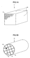
- FIG. 1A illustrates the honeycomb structure 11, which is a rectangular solid having a square honeycomb cross section.
- the honeycomb structure 11 includes plural through-holes 12 arranged in parallel from the front side to the back side, and the outer side walls 13 without through-holes.
- the area of the cross section of the honeycomb structure 11 perpendicular to the through-holes 12 is from 5 to 50 cm 2 , more preferably, from 6 to 40 cm 2 , and still more preferably, from 8 to 30 cm 2 .
- the area of the honeycomb cross section is less than 5 cm 2 , the cross-sectional area of the sealing material layers 14, which seal the honeycomb structures 11, becomes relatively large, the pressure loss increases, and in addition, the specific surface area becomes small.
- the area of the honeycomb cross section is greater than 50 cm 2 , the honeycomb structures 11 become large, thus, it becomes difficult to reduce the thermal stress in each of the honeycomb structures 11.
- the open area ratio is defined to be a ratio of a sum of areas of the through-holes 12 of the honeycomb structure to the honeycomb cross section.
- the wall thickness between the through-holes 12 is less than or equal to 0.25 mm, more preferably, less than or equal to 0.22 mm, and still more preferably, less than or equal to 0.20 mm. Below 0.22 mm the catalyst being carried can be utilized more efficiently.
- the wall thickness between the through-holes 12 is less than 0.10 mm, the strength of the honeycomb structure becomes lessened, hence, it is preferable that the wall thickness be greater than or equal to 0.10 mm.
- the number of the through-holes 12 per unit cross-sectional area be from 15.5 to 186/cm 2 (from 100 to 1200 cpsi), more preferably, from 46.5 to 170.5/cm 2 (from 300 to 1100 cpsi), and still more preferably, from 62.0 to 155/cm 2 (from 400 to 1000 cpsi).
- the number of the through-holes 12 per unit cross-sectional area is less than 15.5, the area of the inner wall contacting the exhaust gas in the honeycomb structures 11 becomes small, and when the number of the through-holes 12 per unit cross-sectional area is greater than 186, the pressure loss increases, and it becomes difficult to fabricate the honeycomb structures 11.
- extrusion molding is performed by using a raw material paste with the above-mentioned ceramic particles and inorganic binders as main ingredients, thereby forming a honeycomb molding piece. It is more preferable to use a raw material paste with the ceramic particles, the inorganic reinforcement materials, and the inorganic binders as main ingredients.
- a raw material paste in addition to the above materials, an organic binder, a dispersive medium, and a molding agent may be added when necessary according to the moldability.
- the organic binders may be one or more selected from a group of methylcellulose, carboxymethylcellulose, hydroxyethylcellulose, polyethylene glycol, phenolic resin, and epoxy resin.
- the composition of the organic binders is 1 to 10 parts by weight (w/t part) assuming the total weight of the ceramic particles and the inorganic binders is 100 parts by weight (w/t part).
- the loading of the organic binders is 1 to 10 parts by weight (w/t part) assuming the total weight of the ceramic particles, the inorganic reinforcement materials, and the inorganic binders is 100 parts by weight (w/t part).
- the dispersive medium may be water, organic solvent (like benzene), alcohol (like methanol), or others.
- the molding agent may be ethylene glycol, dextrin, aliphatic acid, fatty acid soap, polyalcohol, or others.
- the method of forming the raw material paste there is no limitation on the method of forming the raw material paste.
- mixing and kneading are preferable.
- a mixer or an agitator may be used for mixing, and a kneader may be used for kneading.
- a shape having the through holes can be formed by extrusion molding.
- the thus obtained molding piece is dried.
- Any kind of dryer can be used, for example, use can be made of a microwave dryer, a hot air dryer, a dielectric dryer, a low-pressure dryer, a vacuum dryer, or a freezing dryer.
- the thus obtained molding piece is degreased.
- the degreasing conditions can be selected appropriately according to the types and amounts of organic materials included in the molding piece.
- degreasing is performed at a temperature of about 400 °C for about two hours.
- the thus obtained molding piece is fired.
- firing is performed at a temperature from 600 °C to 1000 °C.
- firing temperature is lower than 600 °C, firing of the ceramic particles does not proceed, and the strength of the honeycomb structure may decrease. If the firing temperature is higher than 1000 °C, the ceramic particles are sintered too much, the specific surface area decreases, and the catalyst elements being carried cannot be highly dispersed.
- the honeycomb structure having plural through-holes can be formed.
- a sealing material which becomes the sealing material layers 14, is applied on the thus obtained honeycomb structure, and plural such honeycomb structures are bonded one by one, and are dried and fixed afterwards to fabricate a honeycomb structure aggregate.
- the sealing material may be a mixture of ceramic particles and an inorganic binder, or a mixture of an inorganic binder and an inorganic reinforcement material, or a mixture of ceramic particles, an inorganic binder, and an inorganic reinforcement material.
- an organic binder can be added to the sealing material.
- the organic binder may be one or more selected from a group of polyvinyl alcohol, methylcellulose, ethylcellulose, and carboxymethylcellulose.
- the sealing material be 0.5 to 2 mm in thickness. If the thickness of the sealing material is less than 0.5 mm, it is difficult to obtain sufficient bonding strength. Meanwhile, because the sealing material does not function as a catalyst carrier, if the thickness of the sealing material is greater than 2 mm, the specific surface area decreases, and when catalyst elements are being carried, the catalyst elements cannot be well dispersed.
- the number of the bonded honeycomb structures can be appropriately decided according to the size of the honeycomb structure aggregate in use, which includes the bonded honeycomb structures carrying the catalyst elements.
- the honeycomb structure aggregate can be appropriately cut or polished according to its size and shape in use.
- a coating material is applied to the outside surface (side surfaces) of the honeycomb structure aggregate, on which the through-holes are not formed, and dried and fixed afterward to form a coating material layer. Due to this, it is possible to protect the outside surface and increase the strength.
- the coating material It may be formed from the same material as the sealing material, or from materials different from the sealing material.
- the composition of the coating material may be the same as that of the sealing material, or different from that of the sealing material.
- the thickness of the coating material there is no limitation on the thickness of the coating material.
- the coating material is 0.1 to 2 mm in thickness. If the thickness of the coating material is less than 0.1 mm, it is difficult to protect the outside surface and increase the strength. Meanwhile, if the thickness of the coating material is greater than 2 mm, the specific surface area of the honeycomb structure aggregate decreases, and when catalyst elements are being carried, the catalyst elements cannot be well dispersed.
- the ratio of the sum of the cross-sectional areas of the honeycomb structures in a cross section perpendicular to the longitudinal direction to the cross-sectional area of the honeycomb structure aggregate in the cross section perpendicular to the longitudinal direction is greater than or equal to 85%, and more preferably, the ratio is greater than or equal to 90%. If the ratio is less than 85%, the proportion of the honeycomb structures decreases, thus the specific surface area of the honeycomb structure aggregate decreases.
- FIG. 1B is a schematic view of a cylindrical honeycomb structure aggregate 10 which is obtained by bonding plural solid rectangular honeycomb structures 11 (refer to FIG. 1A) each having a square cross section.
- the honeycomb structures 11 are bonded together by the sealing material layers 14, and are cut into a cylindrical shape. Then, the outer surface of the honeycomb structure aggregate 10 without through-holes is covered by a coating material layer 16.
- the honeycomb structure aggregate 10 shown in FIG. 1B may be fabricated by shaping the cross sections of the honeycomb structures into a square or a sector, and bonding these honeycomb structures 11 together to form a certain shape (in FIG. 1B, a cylinder). In doing so, cutting and polishing steps may be omitted.
- honeycomb structure aggregate 10 there is no limitation on applications of the thus obtained honeycomb structure aggregate 10 (or the honeycomb structures 11).
- the honeycomb structure aggregate 10 may be used as a catalyst carrier for converting exhaust gas from vehicles.
- the honeycomb structure aggregate 10 when used as a catalyst carrier for converting exhaust gas from a Diesel engine, it may be used together with a Diesel particulate filter (DPF), which includes silicon carbide or other ceramic honeycomb structures to filter particulate materials (PM) in the exhaust gas, and has combustion purification functions.
- DPF Diesel particulate filter
- the honeycomb structure aggregate 10 of the present invention may be arranged in front (upstream) of or behind (downstream of) the DPF.
- honeycomb structure aggregate 10 When the honeycomb structure aggregate 10 is arranged in front of the DPF, if exothermic reactions occur in the honeycomb structure aggregate 10 of the present invention, heat can be transmitted to the DPF behind, causing rise of the temperature during regeneration of the DPF. In the meantime, when the honeycomb structure aggregate 10 is arranged behind the DPF, since the PM in the exhaust gas is filtered (burned) by the DPF so as to pass through the through-holes of the honeycomb structure aggregate, clogging can hardly occur. Further, when burning the PM by the DPF, gas compositions generated by incomplete combustion can also be processed.
- the thus obtained honeycomb structure aggregate 10 (or the honeycomb structures 11) can carry a catalyst to form a honeycomb catalyst.
- the catalyst may include one or more of a noble metal, an alkali metal, an alkali-earth metal, and an oxide.
- the noble metal may be platinum, palladium, rhodium, or others.
- the alkali metal may be potassium, sodium, or others.
- the alkali-earth metal may be barium or others.
- the oxide may be perovskite (such as, La 0.75 K 0.25 MnO 3 ), CeO 2 , or others.
- honeycomb catalyst there is no limitation on applications of the thus obtained honeycomb catalyst.
- the honeycomb catalyst it is preferable to use the honeycomb catalyst as a three way catalyst or an occlusion-type NOx catalyst.
- the catalyst may be carried after the honeycomb structure is fabricated, or may be carried at the stage of raw materials.
- the honeycomb structure aggregate may be formed after the catalyst is carried by the honeycomb structure, or the honeycomb structure aggregate may be formed first, then the catalyst is carried by the honeycomb structure.
- the specific surface area is greater than or equal to 35,000 m 2 /L. Due to this, it is possible to have the catalyst being carried with the catalyst elements being broadly dispersed all over the honeycomb structure. In the meantime, it is preferable that the specific surface area be less than or equal to 70,000 m 2 /L.
- FIG. 2 illustrates a preferable range of the open area ratio of the honeycomb structure and the specific surface area. The specific surface area is calculated by using equation (2) as explained below.
- the volume of the materials constituting the portion of the honeycomb structure except for the volume of the through-holes is calculated, and a calculation is made of a ratio A (volume %) of the materials constituting the portion of the honeycomb structure except for the volume of the through-holes to the volume (outline shape) of the honeycomb structure.
- the BET specific surface area is measured by "one-point method” in compliance with JIS-R-1626 (1996) set forth in the Japanese Industrial Standards.
- the measurement is made by cutting out cylindrical slices (diameter: 15 mm, length: 15 mm).
- the apparent density C (g/L) of the honeycomb structure is calculated from the weight of the honeycomb structure and the volume corresponding to the outline shape of the honeycomb structure.
- the specific surface area is the surface area per unit apparent volume of the honeycomb structure.
- the specific surface area of the honeycomb structure may be changed by appropriately changing the firing temperature and the firing time. For example, if the firing temperature is lowered, sintering of the materials constituting the honeycomb structure cannot proceed easily, and it is possible to fabricate a honeycomb structure having a high specific surface area. On the other hand, if the firing temperature is raised, sintering of the materials constituting the honeycomb structure develops easily, it is possible to fabricate a honeycomb structure having a small specific surface area. If the firing time is additionally increased, a more significant effect can be obtained.
- the specific surface area of the honeycomb structure may be adjusted by adjusting the particle diameters of the raw materials. Further, when a firing aid is added, the effect becomes more significant; thereby, the specific surface area of the honeycomb structure can be adjusted.
- the firing aid may be a material which is melted at a temperature lower than the firing temperature of the honeycomb structure.
- honeycomb catalyst including catalyst elements carried by the honeycomb structure fabricated under various conditions are explained, together with comparative examples.
- ⁇ alumina particles having average particle diameter of 2 ⁇ m
- silica alumina fibers having average fiber diameter of 10 ⁇ m and average fiber length of 100 ⁇ m
- silica sol solid concentration 30 weight %) in 50 parts by weight, serving as the raw materials of the inorganic binder
- methylcellulose in 6 parts by weight and tiny amounts of plasticizer and lubricant are added into the thus obtained mixture in 100 parts by weight, and are further mixed and kneaded, forming a mixture composition. Then, this mixture composition is extruded by using an extruder to perform extrusion molding, obtaining a raw molding piece.
- FIG. 3 presents a SEM (Scanning Electron Microscopy) picture of the wall surface of the honeycomb structure.
- honeycomb structure is immersed in a platinum nitrate solution, and adjustment is made so that the platinum is carried by the honeycomb structure with the weight of platinum per unit volume of the honeycomb structure being 2g/L. Then, this composition is maintained at 600 °C for one hour, thereby obtaining a honeycomb catalyst with catalyst elements being carried.
- Table 1 summarizes the ceramic particles in the honeycomb catalyst, the wall thickness, the open area ratio X, the shape of the honeycomb structure, the cell density, the length L of the through-holes, the hydraulic diameter d of the through-holes, L/d, the firing temperature, and the firing time.
- a cylindrical cordierite honeycomb structure (diameter: 143.8 mm, length: 150 mm) available in the market, which has an alumina catalyst carrying layer inside the through-holes, was cut into square-pillar shapes (34.3mm x 34.3mm x 150 mm).
- catalyst elements were arranged to be carried by the honeycomb structure, forming a honeycomb catalyst.
- the cell shape was a hexagon
- the wall thickness was 0.25 mm
- the open area ratio was 56%
- the cell density was 62/cm 2 (400 cpsi).
- the specific surface area of the honeycomb structure before the catalyst elements were disposed was measured. First, the volume of the materials constituting the portion of the honeycomb structure except for the volume of the through-holes was calculated, and a calculation was made of a ratio A (volume %) of the materials constituting the portion of the honeycomb structure to the volume (outline shape) of the honeycomb structure. Next, a measurement was made of a BET specific surface area per unit weight of the honeycomb structure (m 2 /g) (denoted as "B").
- the BET specific surface area was measured by "one-point method” in compliance with JIS-R-1626 (1996) set forth in Japanese Industrial Standards by using a BET measurement device "Micrometitics” FlowSorb II-2300 (manufactured by Shimadzu Co.). In the measurement, samples were used which were obtained by cutting out cylindrical slices (diameter: 15 mm, length: 15 mm) from the honeycomb structure. Then, the apparent density C (g/L) of the honeycomb structure was calculated from the weight of the honeycomb structure and the volume corresponding to the outline shape of the honeycomb structure. The specific surface area S (m 2 /L) of the honeycomb structure was calculated by using the above equation (2). It was found that the specific surface area of the honeycomb structure was approximately the same as the specific surface area of the honeycomb structure with catalyst elements disposed thereon.
- Light-off temperature is a reaction temperature when a conversion rate is 50%.
- the conversion rate is defined to be a rate of reduction of a concentration of a specific component included in exhaust gas caused by a catalyst.
- the light-off temperature is low, accordingly, the component in the exhaust gas can be converted without the necessity of imposing the corresponding portion of energy.
- a honeycomb catalyst having a low light-off temperature is of high catalytic performance. Therefore, the light-off temperature is used as an index indicating the catalytic performance of a honeycomb catalyst.
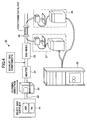
- a method of measuring the light-off temperature This measurement can be made by using a catalytic reaction device 20 as shown in FIG. 4.
- the catalytic reaction device 20 has a supplier 21 of a dilute gas including air and nitrogen, a flowing channel 22 for the flow of the dilute gas to the honeycomb structure, a humidifier 23 for humidifying the dilute gas, a heater 24 for heating the dilute gas, a gas mixer 25 for mixing exhaust gas components into the heated dilute gas to prepare a reaction gas, an airtight sample holder 26 for holding the honeycomb structure, a gas sampler 27 for sampling the reaction gas before it contacts the honeycomb structure, and a gas analyzer 29 for analyzing concentration of a certain gas component included in the reaction gas.
- the honeycomb catalyst was placed in the sample holder 26, and air and nitrogen were supplied to flow from the dilute gas supplier 21 to the flowing channel 22.
- the dilute gas was humidified by the humidifier 23, and was adjusted to a preset temperature by the heater 24.
- exhaust gas components were injected into the flowing dilute gas, and were mixed by the gas mixer 25 to prepare a reaction gas having a certain concentration.
- the prepared reaction gas was directed to flow to the honeycomb catalyst in the sample holder 26 to convert the reaction gas.
- the temperature of the heater 24 was appropriately adjusted, the temperatures of the reaction gas inside the honeycomb catalyst at different heater temperatures were measured by using a not-illustrated thermocouple, and the concentrations of the reaction gas sampled by the gas samplers 27, 28 were measured by the gas analyzer 29.
- a honeycomb catalyst having a 34.3 mm x 34.3 mm cross section and a length of 150 mm was used.
- the catalytic reaction was performed under conditions that the flow rate of the reaction gas was 131 L/minute; the exhaust gas components included oxygen, carbon oxides, sulfur dioxide, carbon hydrides, nitrogen oxides, water vapor, and nitrogen; in the reaction gas, the concentration of oxygen was 13%, the concentration of carbon oxides was 300 ppm, the concentration of sulfur dioxide was 8 ppm, the concentration of carbon hydrides based on the amount of carbon was 300 ppm, the concentration of nitrogen oxides was 160 ppm, and an amount of humidification was added more or less.
- reaction temperature was adjusted by changing the temperature of the heater 24 10 °C each time in a range from 50 to 400 °C.
- concentrations of the carbon oxides and carbon hydrides were measured by the gas analyzer 29.
- FIG. 5A presents measurement results expressing the relationship between the reaction temperature and the conversion rate of the carbon oxides (CO) in example 1 and comparative example 18.
- FIG. 5B presents measurement results expressing the relationship between the reaction temperature and the conversion rate of the carbon hydrides (CH) in example 1 and comparative example 18.
- Table 2 summarizes the wall thickness, the open area ratio X, the specific surface area Y, the value of the formula 250X+2500, and the light-off temperature.
- examples 1-16 are in the preferable range as shown in FIG. 2. Further, it is found that the honeycomb structure as described by equation (1) has high catalytic performance when the wall thickness is less than or equal to 0.25 mm, and the length of the through-holes is equal to or greater than 50-fold of a hydraulic diameter of each of the through-holes and less than or equal to 350-fold of the hydraulic diameter of the through-holes.
- a heat-resistant sealing paste was prepared by mixing ⁇ alumina particles (having average particle diameter of 2 ⁇ m) in 29 parts by weight, silica alumina fibers (having average fiber diameter of 10 ⁇ m, and average fiber length of 100 ⁇ m) in 7 parts by weight, silica sol (solid concentration 30 weight %) in 34 parts by weight, carboxymethylcellulose in 5 parts by weight, and water in 25 parts by weight.
- silica sol solid concentration 30 weight %) in 34 parts by weight
- carboxymethylcellulose in 5 parts by weight
- water 25 parts by weight
- FIG. 6 is a schematic view of the honeycomb structure aggregate obtained by bonding plural honeycomb structures 11, showing a cross section of the honeycomb structure aggregate having the through-holes.
- This honeycomb structure aggregate is fabricated by applying the sealing paste to the outside surface of the honeycomb structure aggregate to a thickness of 1 mm so as to bond the plural honeycomb structures 11. After the honeycomb structure aggregate was fabricated in this way, a diamond cutter was used to cut the honeycomb structure aggregate into circular cylindrical shape so that the front face of the aggregate was of point symmetry, and the sealing paste was applied to the circular outside surface 16 without the through-holes 12 to a thickness of 0.5 mm to form a coating on the outside surface 16.
- the aggregate was dried at 120 °C, and maintained at 700 °C for two hours to degrease the sealing material layer and the coating material layer, thereby obtaining a circular cylindrical honeycomb structure aggregate 10 (diameter: 143.8 mm, length: 150 mm) as shown in FIG. 1B.
- catalyst elements were disposed to be carried by the honeycomb structure aggregate 10, forming a honeycomb structure aggregate with catalyst elements being carried thereon.
- the present invention can be used as a carrier of a catalyst for converting exhaust gas from a vehicle.
- the present invention can be used as an absorbent for absorbing gas components or liquid components. While the invention has been described with reference to preferred embodiments, the invention is not limited to these embodiments, but numerous modifications could be made thereto without departing from the basic concept and scope described in the claims.
Landscapes
- Chemical & Material Sciences (AREA)
- Physics & Mathematics (AREA)
- Geometry (AREA)
- Chemical Kinetics & Catalysis (AREA)
- Engineering & Computer Science (AREA)
- Mechanical Engineering (AREA)
- Combustion & Propulsion (AREA)
- General Engineering & Computer Science (AREA)
- Ceramic Engineering (AREA)
- Health & Medical Sciences (AREA)
- Toxicology (AREA)
- Catalysts (AREA)
- Exhaust Gas Treatment By Means Of Catalyst (AREA)
- Exhaust Gas After Treatment (AREA)
Abstract
Description
- The present invention relates to a honeycomb structure, a honeycomb structure aggregate, and a honeycomb catalyst.
- In the related art, a honeycomb catalyst, which includes a medium carried by a honeycomb structure and is used for conversion of exhaust gas from vehicles, is fabricated by disposing materials of high specific surface area like active alumina and catalysts like platinum on the surface of a monolithic cordierite-based honeycomb structure. In addition, the honeycomb catalyst carries an alkali-earth metal like barium to act as an occlusion-type NOx catalyst for processing NOx in an oxygen-rich atmosphere, such as atmospheres in a lean-burn engine or a Diesel engine.
- In order to further improve conversion performance, it is necessary to increase the contact probability between the exhaust gas and the catalyst element and the NOx occlusion agent as well. For this purpose, it is required to increase the specific surface area of the carrier, decrease diameters of catalyst elements and highly disperse the catalyst elements. However, if simply increasing the amount of the materials of high specific surface areas like active alumina, it is the thickness of the active alumina layer only that is increased, and it does not lead to an increase of the contact probability, but results in a pressure loss. For this reason, modifications have been made on cell shapes, cell densities, wall thicknesses, and so on. For example, see
JP-A10-263416 reference 1"). - On the other hand, a honeycomb structure formed from materials of high specific surface areas is known to be formed by extrusion molding of the materials of high specific surface areas together with inorganic fibers and inorganic binders. For example, see
JP-A5-213681 - Further, a honeycomb structure is known, which is obtained by extrusion molding of the materials of high specific surface areas and having a catalyst being carried by the materials. In the honeycomb structure, the thickness of a partition wall (referred to as wall thickness, below) between through-holes, the length along a gas flowing direction, the length of one side of the through-holes, and an open area ratio are adjusted to be preset values. For example, see
JP-A2003-245547 - However, the above-mentioned techniques in the related art suffer from the following problems.
- As for the honeycomb catalyst disclosed in
reference 1, in which high specific surface area materials like active alumina and catalysts like platinum are disposed on the surface of a cordierite-based honeycomb structure, in order to increase the contact probability with the exhaust gas, modifications have been made on cell shapes, cell densities, wall thicknesses, and others to increase the specific surface area of the catalyst carrier. However, because of the pressure loss and other problems, the specific surface area is not adequate. For this reason, the catalyst elements are not well dispersed, and the ability of converting the exhaust gas after thermal ageing is not sufficient. To solve this problem, it is attempted to have a larger amount of catalyst elements being carried, or to increase the size of the catalyst carrier. - However, catalysts like platinum are very expensive, and are valuable resources of quite limited amounts. In addition, when disposing the catalysts in a vehicle, the space for disposing the catalysts is quite limited. So far, there is not an appropriate solution to the problem.
- As for the honeycomb structure disclosed in reference 2, because it is formed by extrusion molding of the materials of high specific surface areas together with the inorganic fibers and inorganic binders, and the catalyst carrier is also of a high specific surface area, it is possible to well disperse the catalyst elements. However, by just increasing the specific surface area of the catalyst carrier, sometimes it is difficult to increase the contact probability between the exhaust gas and the catalyst elements; thus it is difficult to convert the exhaust gas efficiently.
- As for the honeycomb structure disclosed in reference 3, study is made of the relation between functions of the catalyst and parameters such as the wall thickness, the length along the gas flowing direction, the length of one side of the through-holes, and the open area ratio. However, definition of these parameters does not always guarantee the exhaust gas can be converted efficiently.
- An object of the present invention is to solve the above problems by providing a honeycomb structure, a honeycomb structure aggregate, and a honeycomb catalyst enabling sufficient contact between a catalyst and exhaust gas and efficient conversion of the exhaust gas.
- The present invention provides a honeycomb structure including a plurality of through-holes separated by a plurality of partition walls and provided in parallel along a longitudinal direction, wherein a thickness of each of the partition walls is less than or equal to 0.25 mm, a length of each of the through-holes is equal to or greater than 50-fold of a hydraulic diameter of each of the through-holes and less than or equal to 350-fold of the hydraulic diameter of each of the through-holes, and an open area ratio (X)% of a cross section of the honeycomb structure perpendicular to the through-holes and a surface area per unit volume (Y (m2/L)) satisfy:

- According to the present invention, it is possible to provide a honeycomb structure enabling sufficient contact between a catalyst and exhaust gas and efficient conversion of the exhaust gas.
- In addition, in the honeycomb structure, preferably the thickness of each of the partition walls is equal to or greater than 0.10 mm.
- According to the present invention, it is possible to improve strength of the honeycomb structure.
- In addition, in the honeycomb structure, preferably the honeycomb structure is formed from a mixture of ceramic particles and an inorganic binder.
- According to the present invention, it is possible to improve strength of the honeycomb structure, and at the same time, it is possible to improve the surface area per unit volume.
- In addition, in the honeycomb structure, preferably as solid concentrations, the mixture includes ceramic particles from 30% to 90% in weight, and the inorganic binder from 5% to 50% in weight.
- According to the present invention, it is possible to improve strength of the honeycomb structure, and at the same time, it is possible to improve the surface area per unit volume.
- In addition, in the honeycomb structure, preferably the surface area per unit volume is greater than or equal to 35000 m2/L and less than or equal to 70000 m2/L.
- According to the present invention, it is possible to highly disperse catalyst elements.
- The present invention provides a honeycomb structure aggregate, comprising a plurality of the honeycomb structures as claimed in any one of the
claims 1 to 5, wherein the honeycomb structures are bonded together by sealing material layers. - According to the present invention, it is possible to improve heat resistance and shock resistance.
- In addition, in the honeycomb structure aggregate, preferably a thickness of each of the sealing material layers is greater than or equal to 0.5 mm and less than or equal to 2 mm.
- According to the present invention, it is possible to reduce pressure loss to be low and improve bonding strength.
- The present invention provides a honeycomb catalyst, comprising the honeycomb structure with a catalyst being carried by the honeycomb structure.
- According to the present invention, it is possible to provide a honeycomb catalyst able to efficiently convert the exhaust gas.
- The present invention provides a honeycomb catalyst, comprising the honeycomb structure aggregate with a catalyst being carried by the honeycomb structure aggregate.
- According to the present invention, it is possible to provide a honeycomb catalyst able to efficiently convert the exhaust gas.
- In addition, in the honeycomb structure aggregate, preferably the catalyst includes one or more selected from a group of a noble metal, an alkali metal, an alkali-earth metal, and an oxide.
- According to the present invention, it is possible to improve conversion capability.
- In addition, preferably, the honeycomb catalyst is used to convert exhaust gas from a vehicle.
- According to the present invention, it is possible to provide a honeycomb structure, a honeycomb structure aggregate, and a honeycomb catalyst enabling sufficient contact between a catalyst and exhaust gas and efficient conversion of the exhaust gas.
- These and other objects, features, and advantages of the present invention will become more apparent from the following detailed description of preferred embodiments given with reference to the accompanying drawings.
-
- FIG. 1A is a schematic view of a honeycomb structure of the present invention;
- FIG. 1B is a schematic view of a honeycomb structure aggregate of the present invention;
- FIG. 2 illustrates a preferable range of an open area ratio and a specific surface area;
- FIG. 3 is a SEM (Scanning Electron Microscopy) picture of a wall surface of the honeycomb structure of the present invention;
- FIG. 4 illustrates a catalytic reaction device;
- FIG. 5A illustrates a relationship between the reaction temperature and the conversion rate of carbon oxides (CO);
- FIG. 5B illustrates a relationship between the reaction temperature and the conversion rate of carbon hydrides (CH); and
- FIG. 6 illustrates a honeycomb structure aggregate of the present invention.
- Below, embodiments of the present invention are explained with reference to the accompanying drawings.
- As illustrated in FIG. 1A, a
honeycomb structure 11 of the present invention includes plural through-holes 12 separated by partition walls 15 and arranged in parallel along a longitudinal direction, and the thickness of each of the partition walls (below, simply referred to as wall thickness) is less than or equal to 0.25 mm, the length of each of the through-holes 12 is equal to or greater than 50-fold of the hydraulic diameter of each of the through-holes 12 and less than or equal to 350-fold of the hydraulic diameter of each of the through-holes 12, and an open area ratio (X)% of a cross section of the honeycomb structure perpendicular to the through-holes 12 and a surface area per unit volume (Y (m2/L)) satisfy:
- With these conditions, it is possible to attain sufficient contact between catalyst elements and exhaust gas and efficiently convert the exhaust gas.
- The reason of this finding is not clear. The inventors, however, attempt to explain this finding in the following way. As described above, generally, in this type of honeycomb structure, it is necessary to increase the contact probability between the exhaust gas and catalyst elements carried by the honeycomb structure. For this purpose, it is effective to increase the specific surface area of the honeycomb structure, decrease diameters of catalyst elements being carried and highly disperse the catalyst elements. With the catalyst elements being highly dispersed, the specific surface area of the catalyst elements is increased; due to this, even when the amount of the catalyst elements being carried is the same, it is probable that the contact probability between the exhaust gas and the catalyst elements is increased.
- In the honeycomb structure, because the exhaust gas flows into the inner portion of the through-holes along the surface of the partition wall, although the exhaust gas infiltrates into the partition wall by diffusion, the distance to the surface of the partition wall, which surface allows contact with the catalyst elements, is limited. Due to this, it is thought that if the wall thickness is greater than 0.25 mm, the amount of the catalyst elements carried in the inner portion of the partition wall increases, where the catalyst elements and the exhaust gas cannot contact each other, so that there is no contribution to conversion. As a result, it is difficult to efficiently convert the exhaust gas.
- In addition, it is believed that if the length of the through-
holes 12 is less than 50-fold of the hydraulic diameter of the through-holes 12, the exhaust gas flows through without contacting the catalyst elements, resulting in degradation of conversion capability, and further, degrading strength of the honeycomb structure. In the meantime, it is believed that if the length of the through-holes 12 is greater than 350-fold of the hydraulic diameter of the through-holes 12, in addition to an increase of the pressure loss, the flow rate of the exhaust gas increases when the exhaust gas flows through the through-holes 12 of thehoneycomb structure 11. This decreases the contact probability with the catalyst elements, and results in degradation of conversion capability. - Thus, it is preferable that the length of the through-
holes 12 be equal to or greater than 50-fold of the hydraulic diameter of the through-holes 12 and less than or equal to 350-fold of the hydraulic diameter of the through-holes 12. More preferably, the length of the through-holes 12 is equal to or greater than 50-fold of the hydraulic diameter of the through-holes 12 and less than or equal to 250-fold of the hydraulic diameter of the through-holes 12. - Note that the hydraulic diameter of the through-
holes 12 is obtained by dividing four-fold of the area of the cross section of thehoneycomb structure 11 perpendicular to the through-hole 12 by the circumferential length of the through-hole 12. - In addition, when the open area ratio (X)% increases, the partition walls 15 of the
honeycomb structure 11 for carrying the catalyst elements become thin. Because it is necessary to increase the speed of absorbing the exhaust gas by the catalyst elements, for this purpose it is effective to increase the specific surface area Y of the honeycomb structure. Therefore, in order to increase the contact probability between the exhaust gas and the catalyst elements carried by the honeycomb structure, and efficiently convert the exhaust gas, it is necessary to define the open area ratio (X)% and the specific surface area Y (surface area per unit volume) to be in an appropriate range. Inventors of the present invention found that when equation (1) is satisfied, it is possible to attain sufficient contact between the catalyst elements and the exhaust gas and to efficiently convert the exhaust gas. - If the open area ratio X is greater than 85%, the exhaust gas flows through without contacting the catalyst elements, resulting in degradation of conversion capability, and further, in degrading the strength of the honeycomb structure. In the meantime, if the open area ratio X is less than 50%, in addition to an increase of the pressure loss, the flow rate increases when the exhaust gas flows through the through-
holes 12 of thehoneycomb structure 11, and this decreases the contact probability with the catalyst elements and results in degradation of conversion capability. - It is preferable that the honeycomb structure of the present invention be formed from a mixture of ceramic particles and an inorganic binder. More preferably, the honeycomb structure of the present invention is formed from a mixture of the ceramic particles and an inorganic reinforcement material. Due to this, the ceramic particles, acting as a base of the catalyst carrier, can be consolidated, and be used as a honeycomb structure having strength sufficient for maintaining at least the shape and having a high specific surface area. In addition, by including the inorganic reinforcement material, the strength can be further increased. In addition, as the catalyst elements are dispersed broadly in the whole honeycomb structure and are carried, even when the ceramic particles are not sufficiently fired for purposes of maintaining a high specific surface area, it becomes possible to maintain the shape even when thermal shock and vibration are imposed.
- As illustrated in FIG. 1B, a honeycomb structure aggregate of the present invention includes
plural honeycomb structures 11 as described above, which are bonded together by sealingmaterial layers 14 atouter side walls 13. In such a honeycomb structure aggregate, the high specific surface area can be increased, and the catalyst elements can be dispersed broadly, and further, the strength against thermal shock and vibration can be increased. - It is thought that this is because even when a temperature distribution is generated in the honeycomb structure aggregate due to a rapid temperature change, the difference of temperatures of individual honeycomb structure can be reduced to be small; alternatively, this is because the thermal shock and the vibration can be attenuated by the sealing material layers 14.
- In addition, even when cracks occur in the honeycomb structure because of thermal stress, the sealing
material layers 14 are able to prevent the cracks from propagating throughout the whole honeycomb structure. Further, the sealingmaterial layers 14 also function as a frame of the honeycomb structure to maintain the shape of the honeycomb structure aggregate so as not to lose the function of a catalyst carrier. - There is no limitation on the ceramic particles. For example, it is preferable to use one or more selected from a group of alumina, silica, zirconia, titanium, cerium, mullite, and zeolite. It is more preferable to use alumina.
- Preferably, the concentration of the ceramic particles included in the honeycomb structure is from 30% to 90% in weight, more preferably, from 40% to 80% in weight, and still more preferably, from 50% to 70% in weight. When the concentration of the ceramic particles is less than 30% in weight, the percentage of the ceramic particles, which contribute to the specific surface area, is small, and the specific surface area of the honeycomb structure decreases; as a result, when carrying the catalyst elements, the catalyst elements cannot be well dispersed. Meanwhile, when the concentration of the ceramic particles is higher than 90% in weight, the percentage of the inorganic reinforcement materials and inorganic binders, which contribute to the strength, is small; as a result, the strength of the honeycomb structure decreases.
- There is no limitation on the inorganic reinforcement materials. For example, inorganic fibers and/or whisker, inorganic particles, and others can be used. Preferably, the inorganic fibers and/or whisker may be one or more selected from a group of alumina, silica, silicon carbide, silica alumina, glasses, potassium titanate, and aluminum borate. The inorganic particles may be one or more selected from a group of alumina, silica, zirconia, silicon carbide, and silicon nitride.
- Preferably, the concentration of the inorganic reinforcement materials included in the honeycomb structure is from 3% to 50% in weight, more preferably, from 5% to 40% in weight, and still more preferably, from 8% to 30% in weight. When the concentration of the inorganic reinforcement materials is less than 3% in weight, the percentage of the inorganic reinforcement materials, which materials contribute to the strength, is small; hence, the strength of the honeycomb structure decreases. When the concentration of the inorganic reinforcement materials is greater than 50% in weight, the percentage of the ceramic particles, which particles contribute to the specific surface area, is small, and the specific surface area of the honeycomb structure decreases; as a result, when carrying the catalyst elements, the catalyst elements cannot be well dispersed.
- Preferably, the aspect ratio (length/width) of the inorganic fibers and/or whiskers is from 2 to 1000, more preferably, from 5 to 800, still more preferably, from 10 to 500. When the aspect ratio of the inorganic fibers and/or whisker is less than 2, the contribution to the strength of the honeycomb structure is small; when the aspect ratio of the inorganic fibers and/or whisker is greater than 1000, during molding, clogging occurs in the mold, and it is difficult to perform molding.
- There is no limitation on the inorganic binders. For example, one or more selected from a group of alumina sol, silica sol, titanium sol, soluble glass, sepiolite, and attapulgite may be used.
- Preferably, the concentration of the inorganic binders included in the honeycomb structure is from 5% to 50% in weight, more preferably, from 10% to 40% in weight, and still more preferably, from 15% to 35% in weight. When the concentration of the inorganic binders is less than 5% in weight, the strength of the honeycomb structure decreases; when the concentration of the inorganic binders is greater than 50% in weight, it is difficult to perform molding.
- There is no limitation on the shape of the honeycomb structure. It is preferable to use shapes facilitating binding of the honeycomb structures. For example, a cross section of the honeycomb structure perpendicular to the through-holes (below, referred to as "honeycomb cross section") may be a square, or rectangle, or a sector. As an example of the honeycomb structure, FIG. 1A illustrates the
honeycomb structure 11, which is a rectangular solid having a square honeycomb cross section. Thehoneycomb structure 11 includes plural through-holes 12 arranged in parallel from the front side to the back side, and theouter side walls 13 without through-holes. Preferably, the area of the cross section of thehoneycomb structure 11 perpendicular to the through-holes 12 (below, referred to as "honeycomb cross section") is from 5 to 50 cm2, more preferably, from 6 to 40 cm2, and still more preferably, from 8 to 30 cm2. When the area of the honeycomb cross section is less than 5 cm2, the cross-sectional area of the sealing material layers 14, which seal thehoneycomb structures 11, becomes relatively large, the pressure loss increases, and in addition, the specific surface area becomes small. In the meantime, when the area of the honeycomb cross section is greater than 50 cm2, thehoneycomb structures 11 become large, thus, it becomes difficult to reduce the thermal stress in each of thehoneycomb structures 11. - The open area ratio is defined to be a ratio of a sum of areas of the through-
holes 12 of the honeycomb structure to the honeycomb cross section. - In the present invention, preferably, the wall thickness between the through-
holes 12 is less than or equal to 0.25 mm, more preferably, less than or equal to 0.22 mm, and still more preferably, less than or equal to 0.20 mm. Below 0.22 mm the catalyst being carried can be utilized more efficiently. When the wall thickness between the through-holes 12 is less than 0.10 mm, the strength of the honeycomb structure becomes lessened, hence, it is preferable that the wall thickness be greater than or equal to 0.10 mm. - In addition, it is preferable that the number of the through-
holes 12 per unit cross-sectional area be from 15.5 to 186/cm2 (from 100 to 1200 cpsi), more preferably, from 46.5 to 170.5/cm2 (from 300 to 1100 cpsi), and still more preferably, from 62.0 to 155/cm2 (from 400 to 1000 cpsi). When the number of the through-holes 12 per unit cross-sectional area is less than 15.5, the area of the inner wall contacting the exhaust gas in thehoneycomb structures 11 becomes small, and when the number of the through-holes 12 per unit cross-sectional area is greater than 186, the pressure loss increases, and it becomes difficult to fabricate thehoneycomb structures 11. - Next, descriptions are made of a method of fabricating the honeycomb structure of the present invention. First, extrusion molding is performed by using a raw material paste with the above-mentioned ceramic particles and inorganic binders as main ingredients, thereby forming a honeycomb molding piece. It is more preferable to use a raw material paste with the ceramic particles, the inorganic reinforcement materials, and the inorganic binders as main ingredients. In the raw material paste, in addition to the above materials, an organic binder, a dispersive medium, and a molding agent may be added when necessary according to the moldability.
- There is no limitation on the organic binders. For example, the organic binders may be one or more selected from a group of methylcellulose, carboxymethylcellulose, hydroxyethylcellulose, polyethylene glycol, phenolic resin, and epoxy resin. Preferably, the composition of the organic binders is 1 to 10 parts by weight (w/t part) assuming the total weight of the ceramic particles and the inorganic binders is 100 parts by weight (w/t part). When the raw material paste includes the inorganic reinforcement materials, preferably, the loading of the organic binders is 1 to 10 parts by weight (w/t part) assuming the total weight of the ceramic particles, the inorganic reinforcement materials, and the inorganic binders is 100 parts by weight (w/t part).
- There is no limitation on the dispersive medium. For example, the dispersive medium may be water, organic solvent (like benzene), alcohol (like methanol), or others.
- There is no limitation on the molding agent; for example, the molding agent may be ethylene glycol, dextrin, aliphatic acid, fatty acid soap, polyalcohol, or others.
- There is no limitation on the method of forming the raw material paste. For example, mixing and kneading are preferable. For example, a mixer or an agitator may be used for mixing, and a kneader may be used for kneading.
- There is no limitation on the method of molding the raw material paste. For example, a shape having the through holes can be formed by extrusion molding.
- Next, preferably, the thus obtained molding piece is dried. Any kind of dryer can be used, for example, use can be made of a microwave dryer, a hot air dryer, a dielectric dryer, a low-pressure dryer, a vacuum dryer, or a freezing dryer. In addition, preferably, the thus obtained molding piece is degreased. There is no limitation on conditions of degreasing, but the degreasing conditions can be selected appropriately according to the types and amounts of organic materials included in the molding piece. Preferably, degreasing is performed at a temperature of about 400 °C for about two hours. Preferably, the thus obtained molding piece is fired. There is no limitation on conditions of firing. Preferably, firing is performed at a temperature from 600 °C to 1000 °C. If the firing temperature is lower than 600 °C, firing of the ceramic particles does not proceed, and the strength of the honeycomb structure may decrease. If the firing temperature is higher than 1000 °C, the ceramic particles are sintered too much, the specific surface area decreases, and the catalyst elements being carried cannot be highly dispersed.
- Through the above steps, the honeycomb structure having plural through-holes can be formed.
- Next, a sealing material, which becomes the sealing material layers 14, is applied on the thus obtained honeycomb structure, and plural such honeycomb structures are bonded one by one, and are dried and fixed afterwards to fabricate a honeycomb structure aggregate.
- There is no limitation on the sealing material. For example, the sealing material may be a mixture of ceramic particles and an inorganic binder, or a mixture of an inorganic binder and an inorganic reinforcement material, or a mixture of ceramic particles, an inorganic binder, and an inorganic reinforcement material. Further, an organic binder can be added to the sealing material. There is no limitation on the organic binder. For example, the organic binder may be one or more selected from a group of polyvinyl alcohol, methylcellulose, ethylcellulose, and carboxymethylcellulose.
- It is preferably that the sealing material be 0.5 to 2 mm in thickness. If the thickness of the sealing material is less than 0.5 mm, it is difficult to obtain sufficient bonding strength. Meanwhile, because the sealing material does not function as a catalyst carrier, if the thickness of the sealing material is greater than 2 mm, the specific surface area decreases, and when catalyst elements are being carried, the catalyst elements cannot be well dispersed. The number of the bonded honeycomb structures can be appropriately decided according to the size of the honeycomb structure aggregate in use, which includes the bonded honeycomb structures carrying the catalyst elements. The honeycomb structure aggregate can be appropriately cut or polished according to its size and shape in use.
- A coating material is applied to the outside surface (side surfaces) of the honeycomb structure aggregate, on which the through-holes are not formed, and dried and fixed afterward to form a coating material layer. Due to this, it is possible to protect the outside surface and increase the strength.
- There is no limitation on the coating material. It may be formed from the same material as the sealing material, or from materials different from the sealing material. In addition, the composition of the coating material may be the same as that of the sealing material, or different from that of the sealing material.
- There is no limitation on the thickness of the coating material. Preferably, the coating material is 0.1 to 2 mm in thickness. If the thickness of the coating material is less than 0.1 mm, it is difficult to protect the outside surface and increase the strength. Meanwhile, if the thickness of the coating material is greater than 2 mm, the specific surface area of the honeycomb structure aggregate decreases, and when catalyst elements are being carried, the catalyst elements cannot be well dispersed.
- In addition, preferably, the ratio of the sum of the cross-sectional areas of the honeycomb structures in a cross section perpendicular to the longitudinal direction to the cross-sectional area of the honeycomb structure aggregate in the cross section perpendicular to the longitudinal direction is greater than or equal to 85%, and more preferably, the ratio is greater than or equal to 90%. If the ratio is less than 85%, the proportion of the honeycomb structures decreases, thus the specific surface area of the honeycomb structure aggregate decreases.
- After plural honeycomb structures are bonded with the sealing materials (when the coating materials are provided, after the coating material layers are formed), it is preferable to perform calcination. In doing so, it is possible to perform degreasing when the organic binder is included in the sealing materials and the coating materials. The degreasing conditions may be determined appropriately according to types and loadings of the organic materials. Preferably, calcination is performed at about 700 °C for about two hours. As an example of the honeycomb structure aggregate, FIG. 1B is a schematic view of a cylindrical
honeycomb structure aggregate 10 which is obtained by bonding plural solid rectangular honeycomb structures 11 (refer to FIG. 1A) each having a square cross section. To form thehoneycomb structure aggregate 10, thehoneycomb structures 11 are bonded together by the sealing material layers 14, and are cut into a cylindrical shape. Then, the outer surface of thehoneycomb structure aggregate 10 without through-holes is covered by acoating material layer 16. Alternatively, thehoneycomb structure aggregate 10 shown in FIG. 1B, for example, may be fabricated by shaping the cross sections of the honeycomb structures into a square or a sector, and bonding thesehoneycomb structures 11 together to form a certain shape (in FIG. 1B, a cylinder). In doing so, cutting and polishing steps may be omitted. - There is no limitation on applications of the thus obtained honeycomb structure aggregate 10 (or the honeycomb structures 11). For example, it is preferable to use the
honeycomb structure aggregate 10 as a catalyst carrier for converting exhaust gas from vehicles. In addition, when thehoneycomb structure aggregate 10 is used as a catalyst carrier for converting exhaust gas from a Diesel engine, it may be used together with a Diesel particulate filter (DPF), which includes silicon carbide or other ceramic honeycomb structures to filter particulate materials (PM) in the exhaust gas, and has combustion purification functions. In this case, thehoneycomb structure aggregate 10 of the present invention may be arranged in front (upstream) of or behind (downstream of) the DPF. When thehoneycomb structure aggregate 10 is arranged in front of the DPF, if exothermic reactions occur in thehoneycomb structure aggregate 10 of the present invention, heat can be transmitted to the DPF behind, causing rise of the temperature during regeneration of the DPF. In the meantime, when thehoneycomb structure aggregate 10 is arranged behind the DPF, since the PM in the exhaust gas is filtered (burned) by the DPF so as to pass through the through-holes of the honeycomb structure aggregate, clogging can hardly occur. Further, when burning the PM by the DPF, gas compositions generated by incomplete combustion can also be processed. - The thus obtained honeycomb structure aggregate 10 (or the honeycomb structures 11) can carry a catalyst to form a honeycomb catalyst. There is no limitation on the catalyst. For example, the catalyst may include one or more of a noble metal, an alkali metal, an alkali-earth metal, and an oxide. For example, the noble metal may be platinum, palladium, rhodium, or others. The alkali metal may be potassium, sodium, or others. The alkali-earth metal may be barium or others. The oxide may be perovskite (such as, La0.75K0.25MnO3), CeO2, or others.
- There is no limitation on applications of the thus obtained honeycomb catalyst. For example, it is preferable to use the honeycomb catalyst as a three way catalyst or an occlusion-type NOx catalyst.
- There is no limitation on the way of carrying the catalyst. The catalyst may be carried after the honeycomb structure is fabricated, or may be carried at the stage of raw materials.
- As for the honeycomb structure aggregate, the honeycomb structure aggregate may be formed after the catalyst is carried by the honeycomb structure, or the honeycomb structure aggregate may be formed first, then the catalyst is carried by the honeycomb structure.
- There is no limitation on the method of having the catalyst being carried. For example, impregnation may be used.
- In the honeycomb structure, preferably the specific surface area is greater than or equal to 35,000 m2/L. Due to this, it is possible to have the catalyst being carried with the catalyst elements being broadly dispersed all over the honeycomb structure. In the meantime, it is preferable that the specific surface area be less than or equal to 70,000 m2/L. FIG. 2 illustrates a preferable range of the open area ratio of the honeycomb structure and the specific surface area. The specific surface area is calculated by using equation (2) as explained below.
- Next, an explanation is made of the specific surface area. First, the volume of the materials constituting the portion of the honeycomb structure except for the volume of the through-holes is calculated, and a calculation is made of a ratio A (volume %) of the materials constituting the portion of the honeycomb structure except for the volume of the through-holes to the volume (outline shape) of the honeycomb structure. Next, a measurement is made of a BET specific surface area per unit weight of the honeycomb structure (m2/g) (denoted as "B"). The BET specific surface area is measured by "one-point method" in compliance with JIS-R-1626 (1996) set forth in the Japanese Industrial Standards. Here, the measurement is made by cutting out cylindrical slices (diameter: 15 mm, length: 15 mm). Then, the apparent density C (g/L) of the honeycomb structure is calculated from the weight of the honeycomb structure and the volume corresponding to the outline shape of the honeycomb structure. The specific surface area S (m2/L) of the honeycomb structure can be calculated by the following equation (2).

- Here, the specific surface area is the surface area per unit apparent volume of the honeycomb structure.
- The specific surface area of the honeycomb structure may be changed by appropriately changing the firing temperature and the firing time. For example, if the firing temperature is lowered, sintering of the materials constituting the honeycomb structure cannot proceed easily, and it is possible to fabricate a honeycomb structure having a high specific surface area. On the other hand, if the firing temperature is raised, sintering of the materials constituting the honeycomb structure develops easily, it is possible to fabricate a honeycomb structure having a small specific surface area. If the firing time is additionally increased, a more significant effect can be obtained. In addition, since when the raw materials of the honeycomb structure have small particle diameters, the sintering of the materials also develops easily even at the same firing temperature, so that the specific surface area of the honeycomb structure may be adjusted by adjusting the particle diameters of the raw materials. Further, when a firing aid is added, the effect becomes more significant; thereby, the specific surface area of the honeycomb structure can be adjusted.
- There is no limitation on the firing aid. For example, the firing aid may be a material which is melted at a temperature lower than the firing temperature of the honeycomb structure.
- Below, examples of the honeycomb catalyst including catalyst elements carried by the honeycomb structure fabricated under various conditions are explained, together with comparative examples.
- First, γ alumina particles (having average particle diameter of 2 µm) in 40 parts by weight, serving as the ceramic particles, silica alumina fibers (having average fiber diameter of 10 µm and average fiber length of 100 µm) in 10 parts by weight, serving as the inorganic fibers, and silica sol (solid concentration 30 weight %) in 50 parts by weight, serving as the raw materials of the inorganic binder, are mixed. Further, methylcellulose in 6 parts by weight and tiny amounts of plasticizer and lubricant are added into the thus obtained mixture in 100 parts by weight, and are further mixed and kneaded, forming a mixture composition. Then, this mixture composition is extruded by using an extruder to perform extrusion molding, obtaining a raw molding piece.
- A microwave dryer and a hot air dryer are used to adequately dry the raw molding piece, and then the raw molding piece is maintained at 400 °C for two hours for degreasing. Afterward, the raw molding piece is maintained at 800 °C for two hours for firing. In this way, a honeycomb structure is obtained which is in a square-pillar shape (34.3mm x 34.3mm x 150 mm), has a cell density of 62/cm2 (400 cpsi), and a wall thickness of 0.25 mm. FIG. 3 presents a SEM (Scanning Electron Microscopy) picture of the wall surface of the honeycomb structure.
- Next, the thus obtained honeycomb structure is immersed in a platinum nitrate solution, and adjustment is made so that the platinum is carried by the honeycomb structure with the weight of platinum per unit volume of the honeycomb structure being 2g/L. Then, this composition is maintained at 600 °C for one hour, thereby obtaining a honeycomb catalyst with catalyst elements being carried.
- Table 1 summarizes the ceramic particles in the honeycomb catalyst, the wall thickness, the open area ratio X, the shape of the honeycomb structure, the cell density, the length L of the through-holes, the hydraulic diameter d of the through-holes, L/d, the firing temperature, and the firing time.
- Using starting materials having the same composition as those in the first example, the same steps were executed as in the first example under conditions as shown in table 1, obtaining corresponding honeycomb structures. In the same way as in the first example, catalyst elements were arranged to be carried by those honeycomb structures, forming corresponding honeycomb catalysts.
- A cylindrical cordierite honeycomb structure (diameter: 143.8 mm, length: 150 mm) available in the market, which has an alumina catalyst carrying layer inside the through-holes, was cut into square-pillar shapes (34.3mm x 34.3mm x 150 mm). Next, in the same way as in the first example, catalyst elements were arranged to be carried by the honeycomb structure, forming a honeycomb catalyst. Here, the cell shape was a hexagon, the wall thickness was 0.25 mm, the open area ratio was 56%, and the cell density was 62/cm2 (400 cpsi).
- The specific surface area of the honeycomb structure before the catalyst elements were disposed was measured. First, the volume of the materials constituting the portion of the honeycomb structure except for the volume of the through-holes was calculated, and a calculation was made of a ratio A (volume %) of the materials constituting the portion of the honeycomb structure to the volume (outline shape) of the honeycomb structure. Next, a measurement was made of a BET specific surface area per unit weight of the honeycomb structure (m2/g) (denoted as "B"). The BET specific surface area was measured by "one-point method" in compliance with JIS-R-1626 (1996) set forth in Japanese Industrial Standards by using a BET measurement device "Micrometitics" FlowSorb II-2300 (manufactured by Shimadzu Co.). In the measurement, samples were used which were obtained by cutting out cylindrical slices (diameter: 15 mm, length: 15 mm) from the honeycomb structure. Then, the apparent density C (g/L) of the honeycomb structure was calculated from the weight of the honeycomb structure and the volume corresponding to the outline shape of the honeycomb structure. The specific surface area S (m2/L) of the honeycomb structure was calculated by using the above equation (2). It was found that the specific surface area of the honeycomb structure was approximately the same as the specific surface area of the honeycomb structure with catalyst elements disposed thereon.
- "Light-off temperature" is a reaction temperature when a conversion rate is 50%. Here, the conversion rate is defined to be a rate of reduction of a concentration of a specific component included in exhaust gas caused by a catalyst. When the light-off temperature is low, accordingly, the component in the exhaust gas can be converted without the necessity of imposing the corresponding portion of energy. Hence, a honeycomb catalyst having a low light-off temperature is of high catalytic performance. Therefore, the light-off temperature is used as an index indicating the catalytic performance of a honeycomb catalyst. Below, an explanation is made of a method of measuring the light-off temperature. This measurement can be made by using a
catalytic reaction device 20 as shown in FIG. 4. Thecatalytic reaction device 20 has asupplier 21 of a dilute gas including air and nitrogen, a flowingchannel 22 for the flow of the dilute gas to the honeycomb structure, ahumidifier 23 for humidifying the dilute gas, aheater 24 for heating the dilute gas, agas mixer 25 for mixing exhaust gas components into the heated dilute gas to prepare a reaction gas, anairtight sample holder 26 for holding the honeycomb structure, agas sampler 27 for sampling the reaction gas before it contacts the honeycomb structure, and agas analyzer 29 for analyzing concentration of a certain gas component included in the reaction gas. - Below, an explanation is made of a procedure for the measurement. First, the honeycomb catalyst was placed in the
sample holder 26, and air and nitrogen were supplied to flow from thedilute gas supplier 21 to the flowingchannel 22. Next, the dilute gas was humidified by thehumidifier 23, and was adjusted to a preset temperature by theheater 24. Next, from the upstream side of thegas mixer 25, exhaust gas components were injected into the flowing dilute gas, and were mixed by thegas mixer 25 to prepare a reaction gas having a certain concentration. The prepared reaction gas was directed to flow to the honeycomb catalyst in thesample holder 26 to convert the reaction gas. In this process, the temperature of theheater 24 was appropriately adjusted, the temperatures of the reaction gas inside the honeycomb catalyst at different heater temperatures were measured by using a not-illustrated thermocouple, and the concentrations of the reaction gas sampled by thegas samplers gas analyzer 29. - In the measurement of the light-off temperature, a honeycomb catalyst having a 34.3 mm x 34.3 mm cross section and a length of 150 mm was used. The catalytic reaction was performed under conditions that the flow rate of the reaction gas was 131 L/minute; the exhaust gas components included oxygen, carbon oxides, sulfur dioxide, carbon hydrides, nitrogen oxides, water vapor, and nitrogen; in the reaction gas, the concentration of oxygen was 13%, the concentration of carbon oxides was 300 ppm, the concentration of sulfur dioxide was 8 ppm, the concentration of carbon hydrides based on the amount of carbon was 300 ppm, the concentration of nitrogen oxides was 160 ppm, and an amount of humidification was added more or less. In addition, the reaction temperature was adjusted by changing the temperature of the
heater 24 10 °C each time in a range from 50 to 400 °C. During this process, among the components included in the reaction gas, concentrations of the carbon oxides and carbon hydrides were measured by thegas analyzer 29. - With the concentration of the reaction gas components before contacting the honeycomb catalyst being C0, the concentration of the reaction gas components after contacting the honeycomb catalyst being Ci, the conversion rate (%) was calculated from equation (3).

- After that, with the temperature of the reaction gas inside the honeycomb catalyst to be the reaction temperature, the relationship between the reaction temperature and the conversion rate was obtained. Then, a graph was plotted with the obtained reaction temperature as abscissa and the conversion rate as ordinate, and then the reaction temperature when the conversion rate was 50% was obtained from the graph, and this temperature was regarded as the "light-off temperature".
- FIG. 5A presents measurement results expressing the relationship between the reaction temperature and the conversion rate of the carbon oxides (CO) in example 1 and comparative example 18.
- FIG. 5B presents measurement results expressing the relationship between the reaction temperature and the conversion rate of the carbon hydrides (CH) in example 1 and comparative example 18.
- As illustrated in FIG. 5A, in example 1, above a certain temperature, the conversion rate increases sharply, and at 140 °C, the conversion rate reaches 100%. In contrast, in comparative example 18, a sharp increase of the conversion rate does not occur, and the temperature at which the conversion rate reaches 100% is higher than that in example 1.
- As illustrated in FIG. 5B, carbon hydrides show the same trend. Therefore, since it is possible to convert (reduce) carbon oxides and carbon hydrides at a low temperature, this reveals that the catalytic performance in example 1 was high.
- In FIG. 5A and FIG. 5B, the light-off temperatures were obtained as indicated by the dotted arrows. The light-off temperatures of other samples were obtained in the same way.
- Table 2 summarizes the wall thickness, the open area ratio X, the specific surface area Y, the value of the
formula 250X+2500, and the light-off temperature. - From these results, it is found that examples 1-16 are in the preferable range as shown in FIG. 2. Further, it is found that the honeycomb structure as described by equation (1) has high catalytic performance when the wall thickness is less than or equal to 0.25 mm, and the length of the through-holes is equal to or greater than 50-fold of a hydraulic diameter of each of the through-holes and less than or equal to 350-fold of the hydraulic diameter of the through-holes.
- A heat-resistant sealing paste was prepared by mixing γ alumina particles (having average particle diameter of 2 µm) in 29 parts by weight, silica alumina fibers (having average fiber diameter of 10 µm, and average fiber length of 100 µm) in 7 parts by weight, silica sol (solid concentration 30 weight %) in 34 parts by weight, carboxymethylcellulose in 5 parts by weight, and water in 25 parts by weight. With this sealing paste, plural honeycomb structures before carrying the catalyst elements were bonded to fabricate a honeycomb structure aggregate.
- FIG. 6 is a schematic view of the honeycomb structure aggregate obtained by bonding
plural honeycomb structures 11, showing a cross section of the honeycomb structure aggregate having the through-holes. - This honeycomb structure aggregate is fabricated by applying the sealing paste to the outside surface of the honeycomb structure aggregate to a thickness of 1 mm so as to bond the
plural honeycomb structures 11. After the honeycomb structure aggregate was fabricated in this way, a diamond cutter was used to cut the honeycomb structure aggregate into circular cylindrical shape so that the front face of the aggregate was of point symmetry, and the sealing paste was applied to the circularoutside surface 16 without the through-holes 12 to a thickness of 0.5 mm to form a coating on theoutside surface 16. Then, the aggregate was dried at 120 °C, and maintained at 700 °C for two hours to degrease the sealing material layer and the coating material layer, thereby obtaining a circular cylindrical honeycomb structure aggregate 10 (diameter: 143.8 mm, length: 150 mm) as shown in FIG. 1B. Then, in the same way as in the first example, catalyst elements were disposed to be carried by thehoneycomb structure aggregate 10, forming a honeycomb structure aggregate with catalyst elements being carried thereon. - For example, the present invention can be used as a carrier of a catalyst for converting exhaust gas from a vehicle. In addition, the present invention can be used as an absorbent for absorbing gas components or liquid components. While the invention has been described with reference to preferred embodiments, the invention is not limited to these embodiments, but numerous modifications could be made thereto without departing from the basic concept and scope described in the claims.
TABLE 1 sample ceramic particles wall thickness X shape cell density L D L/d firing temperature firing time mm % mm /cm2(cpsi) mm mm °C h example 1 alumina 0.25 65 34.3mm square 62(400) 150 1.02 147.1 800 2 example 2 alumina 0.25 50 34.3mm square 140(900) 150 0.60 252.0 900 5 example 3 alumina 0.25 65 34.3mm square 62(400) 150 1.02 147.1 900 3 example 4 alumina 0.25 81 34.3mm square 15.5(100) 150 2.29 65.5 800 2 example 5 alumina 0.25 50 34.3mm square 140(900) 150 0.60 252.0 700 1 example 6 alumina 0.25 81 34.3mm square 15.5(100) 150 2.29 65.5 600 1 example 7 alumina 0.2 60 34.3mm square 124(800) 150 0.70 214.9 800 2 example 8 alumina 0.2 50 34.3mm square 217(1400) 150 0.48 313.3 900 5 example 9 alumina 0.2 60 34.3mm square 124(800) 150 0.70 214.9 900 3 example 10 alumina 0.2 82 34.3mm square 23.3(150) 150 1.87 80.1 800 2 example 11 alumina 0.2 50 34.3mm square 217(1400) 150 0.48 313.3 700 1 example 12 alumina 0.2 82 34.3mm square 23.3(150) 150 1.87 80.1 600 1 comparative example 1 alumina 0.25 40 34.3mm square 217(1400) 150 0.43 349.8 1000 3 comparative example 2 alumina 0.25 40 34.3mm square 217(1400) 150 0.43 349.8 900 8 comparative example 3 alumina 0.25 50 34.3mm square 140(900) 150 0.60 252.0 1000 1 comparative example 4 alumina 0.25 65 34.3mm square 62(400) 150 1.02 147.1 900 4 comparative example 5 alumina 0.25 81 34.3mm square 15.5(100) 150 2.29 65.5 800 3 comparative example 6 alumina 0.25 87 34.3mm square 7.8(50) 150 3.33 45.0 800 1 comparative example 7 alumina 0.25 87 34.3mm square 7.8(50) 150 3.33 45.0 600 1 comparative example 8 alumina 0.3 63 34.3mm square 46.5(300) 150 1.17 128.6 800 2 comparative example 9 alumina 0.3 51 34.3mm square 93(600) 150 0.74 203.5 900 5 comparative example 10 alumina 0.3 63 34.3mm square 46.5(300) 150 1.17 128.6 900 3 comparative example 11 alumina 0.3 81 34.3mm square 10.9(70) 150 2.73 55.0 800 2 comparative example 12 alumina 0.3 51 34.3mm square 93(600) 150 0.74 203.5 700 1 comparative example 13 alumina 0.3 81 34.3mm square 10.9(70) 150 2.73 55.0 600 1 example 13 alumina 0.25 65 22.5mm square 62(400) 350 1.02 343.1 800 2 example 14 alumina 0.25 65 48.6mm square 62(400) 75 1.02 73.5 800 2 example 15 alumina 0.2 60 27.1 mm square 124(800) 240 0.70 343.8 900 3 example 16 alumina 0.2 60 59.5mm square 124(800) 50 0.70 71.6 900 3 comparative example 14 alumina 0.25 65 22.2mm square 62(400) 360 1.02 352.9 800 2 comparative example 15 alumina 0.25 65 59.5mm square 62(400) 50 1.02 49.0 800 2 comparative example 16 alumina 0.2 60 26.6mm square 124(800) 250 0.70 358.2 900 3 comparative example 17 alumina 0.2 60 71.7mm square 124(800) 34.3 0.70 49.1 900 3 comparative example 18 + alumina + cordierite 025 56 34.3mm square 62(400) 150 1.09 138.1 - - TABLE 2 sample ceramic particles wall thickness X Y 250X + 22500 light-off temperature CO HC mm % m2/L °C °C example 1 alumina 0.25 65 55000 38600 110 158 example 2 alumina 0.25 50 35000 34900 124 169 example 3 alumina 0.25 65 39000 38600 122 165 example 4 alumina 0.25 81 43000 42800 118 162 example 5 alumina 0.25 50 52500 34900 113 160 example 6 alumina 0.25 81 57000 42800 108 156 example 7 alumina 0.2 60 55000 37600 108 155 example 8 alumina 0.2 50 35000 34900 121 165 example 9 alumina 0.2 60 38000 37600 119 162 example 10 alumina 0.2 82 43000 42900 116 161 example 11 alumina 0.2 50 52500 34900 109 157 example 12 alumina 0.2 82 57000 42900 107 155 comparative example 1 alumina 0.25 40 32500 32500 142 185 comparative example 2 alumina 0.25 40 45000 32500 132 179 comparative example 3 alumina 0.25 50 30000 34900 146 190 comparative example 4 alumina 0.25 65 35000 38600 126 172 comparative example 5 alumina 0.25 81 40000 42800 126 173 comparative example 6 alumina 0.25 87 43000 44100 127 175 comparative example 7 alumina 0.25 87 50000 44100 140 186 comparative example 8 alumina 0.3 63 55000 38300 125 170 comparative example 9 alumina 0.3 51 35000 35100 140 182 comparative example 10 alumina 0.3 63 37500 38300 138 181 comparative example 11 alumina 0.3 81 42500 42800 128 176 comparative example 12 alumina 0.3 51 52500 35100 128 175 comparative example 13 alumina 0.3 81 57000 42800 126 172 example 13 alumina 0.25 65 55000 38600 121 166 example 14 alumina 0.25 65 55000 38600 124 168 example 15 alumina 0.2 60 55000 37600 122 165 example 16 alumina 0.2 60 55000 37600 124 169 comparative example 14 alumina 0.25 65 55000 38600 130 175 comparative example 15 alumina 0.25 65 55000 38600 133 181 comparative example 16 alumina 0.2 60 55000 37600 129 178 comparative example 17 alumina 0.2 60 55000 37600 134 184 comparative example 18 +alumina + cordierite 0.25 56 27000 36500 160 200
Claims (11)
- A honeycomb structure, comprising:a plurality of through-holes separated by a plurality of partition walls and provided in parallel along a longitudinal direction;whereina thickness of each of the partition walls is less than or equal to 0.25 mm;a length of each of the through-holes is equal to or greater than 50-fold of a hydraulic diameter of each of the through-holes and less than or equal to 350-fold of the hydraulic diameter of each of the through-holes; andan open area ratio (X)% of a cross section of the honeycomb structure perpendicular to the through-holes and a surface area per unit volume (Y (m2/L)) satisfy

- The honeycomb structure as claimed in the claim 1, wherein the thickness of each of the partition walls is equal to or greater than 0.10 mm.
- The honeycomb structure as claimed in the claim 1 or 2, wherein the honeycomb structure is formed from a mixture of ceramic particles and an inorganic binder.
- The honeycomb structure as claimed in the claim 3, wherein as solid concentrations, the mixture includes ceramic particles from 30% to 90% in weight, and the inorganic binder from 5% to 50% in weight.
- The honeycomb structure as claimed in any one of the claims 1 to 4, wherein the surface area per unit volume is greater than or equal to 35000 m2/L and less than or equal to 70000 m2/L.
- A honeycomb structure aggregate, comprising a plurality of the honeycomb structures as claimed in any one of the claims 1 to 5, wherein the honeycomb structures are bonded together by sealing material layers.
- The honeycomb structure aggregate as claimed in the claim 6, wherein a thickness of each of the sealing material layers is greater than or equal to 0.5 mm and less than or equal to 2 mm.
- A honeycomb catalyst, comprising the honeycomb structure as claimed in any one of the claims 1 to 5, wherein a catalyst is carried by the honeycomb structure.
- A honeycomb catalyst, comprising the honeycomb structure aggregate as claimed in the claims 6 or 7, wherein a catalyst is carried by the honeycomb structure aggregate.
- The honeycomb catalyst as claimed in the claims 8 or 9, wherein the catalyst includes one or more selected from a group of a noble metal, an alkali metal, an alkali-earth metal, and an oxide.
- The honeycomb catalyst as claimed in any one of the claims 8 to 10, wherein the honeycomb catalyst is used to convert exhaust gas from a vehicle.
Applications Claiming Priority (1)
| Application Number | Priority Date | Filing Date | Title |
|---|---|---|---|
| PCT/JP2005/011663 WO2006137162A1 (en) | 2005-06-24 | 2005-06-24 | Honeycomb structure body, honeycomb structure body assembly, and honeycomb catalyst |
Publications (1)
| Publication Number | Publication Date |
|---|---|
| EP1736643A1 true EP1736643A1 (en) | 2006-12-27 |
Family
ID=37567793
Family Applications (1)
| Application Number | Title | Priority Date | Filing Date |
|---|---|---|---|
| EP06001897A Withdrawn EP1736643A1 (en) | 2005-06-24 | 2006-01-30 | Honeycomb structure, honeycomb structure aggregate, and honeycomb catalyst |
Country Status (5)
| Country | Link |
|---|---|
| US (1) | US8110274B2 (en) |
| EP (1) | EP1736643A1 (en) |
| JP (1) | JP5042824B2 (en) |
| CN (1) | CN100471570C (en) |
| WO (1) | WO2006137162A1 (en) |
Families Citing this family (41)
| Publication number | Priority date | Publication date | Assignee | Title |
|---|---|---|---|---|
| JP4815108B2 (en) * | 2003-12-26 | 2011-11-16 | イビデン株式会社 | Honeycomb structure |
| JP4527412B2 (en) * | 2004-02-04 | 2010-08-18 | イビデン株式会社 | Honeycomb structure aggregate and honeycomb catalyst |
| WO2009100097A2 (en) | 2008-02-05 | 2009-08-13 | Basf Catalysts Llc | Gasoline engine emissions treatment systems having particulate traps |
| DE602005015122D1 (en) * | 2004-08-31 | 2009-08-06 | Ibiden Co Ltd | EMISSION CONTROL |
| DE602005027173D1 (en) * | 2004-10-08 | 2011-05-12 | Ibiden Co Ltd | HONEY WAVE STRUCTURE AND METHOD OF MANUFACTURE |
| CN1906141B (en) | 2004-12-27 | 2010-11-03 | 揖斐电株式会社 | Honeycomb structure and sealing material layer |
| JP5191657B2 (en) * | 2004-12-27 | 2013-05-08 | イビデン株式会社 | Ceramic honeycomb structure |
| JP5237630B2 (en) * | 2005-02-01 | 2013-07-17 | イビデン株式会社 | Honeycomb structure |
| CN100453511C (en) * | 2005-03-28 | 2009-01-21 | 揖斐电株式会社 | Honeycomb structure and sealing material |
| WO2006137150A1 (en) * | 2005-06-24 | 2006-12-28 | Ibiden Co., Ltd. | Honeycomb structure body |
| CN100457688C (en) * | 2005-06-24 | 2009-02-04 | 揖斐电株式会社 | Honeycomb structure |
| JPWO2006137157A1 (en) * | 2005-06-24 | 2009-01-08 | イビデン株式会社 | Honeycomb structure |
| WO2006137149A1 (en) | 2005-06-24 | 2006-12-28 | Ibiden Co., Ltd. | Honeycomb structure body |
| WO2006137156A1 (en) * | 2005-06-24 | 2006-12-28 | Ibiden Co., Ltd. | Honeycomb structure body |
| CN100434137C (en) * | 2005-06-24 | 2008-11-19 | 揖斐电株式会社 | honeycomb structure |
| WO2006137163A1 (en) * | 2005-06-24 | 2006-12-28 | Ibiden Co., Ltd. | Honeycomb structure body |
| WO2006137151A1 (en) | 2005-06-24 | 2006-12-28 | Ibiden Co., Ltd. | Honeycomb structure and exhaust gas purifier |
| WO2006137160A1 (en) * | 2005-06-24 | 2006-12-28 | Ibiden Co., Ltd. | Honeycomb structure body |
| JPWO2006137158A1 (en) * | 2005-06-24 | 2009-01-08 | イビデン株式会社 | Honeycomb structure |
| WO2006137161A1 (en) * | 2005-06-24 | 2006-12-28 | Ibiden Co., Ltd. | Honeycomb structure body |
| WO2007096986A1 (en) * | 2006-02-24 | 2007-08-30 | Ibiden Co., Ltd. | End face heating apparatus, method of drying end face of honeycomb assembly, and process for producing honeycomb structure |
| US20080118701A1 (en) * | 2006-11-16 | 2008-05-22 | Ibiden Co., Ltd. | Method for manufacturing honeycomb structure, and honeycomb structure |
| WO2008059607A1 (en) * | 2006-11-16 | 2008-05-22 | Ibiden Co., Ltd. | Process for producing honeycomb structure and honeycomb structure |
| EP1923373B1 (en) * | 2006-11-16 | 2010-01-20 | Ibiden Co., Ltd. | Method for manufacturing honeycomb structured body |
| WO2008059576A1 (en) * | 2006-11-16 | 2008-05-22 | Ibiden Co., Ltd. | Honeycomb structural body and method of producing the same |
| JPWO2008096413A1 (en) * | 2007-02-06 | 2010-05-20 | イビデン株式会社 | Honeycomb structure |
| JP5241235B2 (en) * | 2007-02-28 | 2013-07-17 | イビデン株式会社 | Manufacturing method of honeycomb structure |
| WO2008129670A1 (en) * | 2007-04-17 | 2008-10-30 | Ibiden Co., Ltd. | Catalyst-carrying honeycomb and process for producing the same |
| KR100966992B1 (en) * | 2007-05-31 | 2010-06-30 | 그린 하이드로텍 인코포레이티드. | Porous catalyst structure and preparation method thereof |
| WO2009050775A1 (en) * | 2007-10-15 | 2009-04-23 | Ibiden Co., Ltd. | Method for manufacturing honeycomb structure |
| WO2009118815A1 (en) * | 2008-03-24 | 2009-10-01 | イビデン株式会社 | Honeycomb structure |
| JP2010223083A (en) * | 2009-03-23 | 2010-10-07 | Ibiden Co Ltd | Exhaust gas control apparatus and method for manufacturing exhaust gas control apparatus |
| DE102009015420A1 (en) * | 2009-03-27 | 2010-09-30 | Emitec Gesellschaft Für Emissionstechnologie Mbh | Honeycomb body for an exhaust gas purification system |
| US8815189B2 (en) | 2010-04-19 | 2014-08-26 | Basf Corporation | Gasoline engine emissions treatment systems having particulate filters |
| PL3034148T3 (en) * | 2013-08-14 | 2018-10-31 | Sumitomo Chemical Company Limited | Particulate filter |
| JP6373697B2 (en) * | 2014-09-19 | 2018-08-15 | 日本碍子株式会社 | Thermal / sonic conversion parts and thermal / sonic conversion units |
| JP6373696B2 (en) * | 2014-09-19 | 2018-08-15 | 日本碍子株式会社 | Thermal / sonic conversion parts and thermal / sonic conversion units |
| DE102016102506A1 (en) * | 2015-12-22 | 2017-06-22 | Elringklinger Ag | Pack and column comprising one or more packs |
| WO2019195406A1 (en) | 2018-04-04 | 2019-10-10 | Unifrax | Llc | Activated porous fibers and products including same |
| JP7155292B2 (en) * | 2018-05-04 | 2022-10-18 | コーニング インコーポレイテッド | Extrusion dies for high isostatic strength honeycomb structures and honeycomb structures |
| JP6840283B1 (en) * | 2020-10-19 | 2021-03-10 | 株式会社三井E&Sマシナリー | Honeycomb catalyst structure and SCR device |
Citations (6)
| Publication number | Priority date | Publication date | Assignee | Title |
|---|---|---|---|---|
| JPH03245547A (en) | 1990-02-23 | 1991-11-01 | Hitachi Ltd | Image filing system |
| JPH05213681A (en) | 1992-01-31 | 1993-08-24 | Kawata Mfg Co Ltd | Honeycomb fiber-reinforced ceramic body and method for manufacturing the same |
| JPH10263416A (en) | 1997-01-21 | 1998-10-06 | Toyota Motor Corp | Exhaust gas purification catalyst |
| EP1482138A1 (en) * | 2002-03-01 | 2004-12-01 | Ngk Insulators, Ltd. | Exhaust emission control system, method of calculating pressure loss of filter, and method of manufacturing filter |
| WO2005075075A1 (en) * | 2004-02-04 | 2005-08-18 | Ibiden Co., Ltd. | Honeycomb structure, honeycomb structure assembly, and honeycomb catalyst |
| EP1598102A1 (en) * | 2003-02-28 | 2005-11-23 | Ibiden Co., Ltd. | Ceramic honeycomb structure |
Family Cites Families (60)
| Publication number | Priority date | Publication date | Assignee | Title |
|---|---|---|---|---|
| DE3167287D1 (en) | 1980-05-27 | 1985-01-03 | Corning Glass Works | Catalytic converter |
| JP2736099B2 (en) * | 1989-02-06 | 1998-04-02 | 株式会社日本触媒 | Diesel engine exhaust gas purification catalyst |
| JP2904431B2 (en) | 1993-03-26 | 1999-06-14 | 日本碍子株式会社 | Exhaust gas purification equipment |
| JP2892259B2 (en) * | 1993-07-29 | 1999-05-17 | 日本碍子株式会社 | Ceramic honeycomb catalyst |
| DE4341159B4 (en) | 1993-12-02 | 2009-02-05 | Argillon Gmbh | Honeycomb catalyst and process for its preparation |
| US5518678A (en) * | 1994-01-26 | 1996-05-21 | Kawata Manufacturing Co., Ltd. | Adsorptive honeycomb-shaped ceramic structure and method for its production |
| JPH0812460A (en) | 1994-06-22 | 1996-01-16 | Osamu Yamamoto | Honeycomb ceramic structure |
| US5914187A (en) | 1996-01-12 | 1999-06-22 | Ibiden Co., Ltd. | Ceramic structural body |
| JP3754502B2 (en) | 1996-07-11 | 2006-03-15 | 株式会社ガスター | Bath kettle with water heater |
| JP3956437B2 (en) | 1996-09-26 | 2007-08-08 | マツダ株式会社 | Exhaust gas purification catalyst |
| DE19745043A1 (en) * | 1997-10-11 | 1999-04-15 | Katalysatorenwerke Huels Gmbh | Process for the destruction of organic halogen compounds in dust-containing gases at low temperature |
| JP3544471B2 (en) | 1998-05-12 | 2004-07-21 | 日本碍子株式会社 | Hexagonal cell honeycomb structure and its gripping method |
| JP2000042420A (en) * | 1998-07-31 | 2000-02-15 | Ibiden Co Ltd | Exhaust gas purifier |
| JP2000210512A (en) | 1999-01-20 | 2000-08-02 | Ngk Insulators Ltd | Ceramic filter and dust collector using that |
| JP2000279823A (en) * | 1999-03-31 | 2000-10-10 | Ngk Insulators Ltd | Ceramic honeycomb structure body and its manufacture |
| JP4146048B2 (en) * | 1999-09-30 | 2008-09-03 | イビデン株式会社 | Honeycomb filter, honeycomb filter assembly, |
| JP2001162119A (en) * | 1999-09-29 | 2001-06-19 | Ibiden Co Ltd | Ceramic filter aggregate |
| JP2001096116A (en) | 1999-09-29 | 2001-04-10 | Ibiden Co Ltd | Ceramic filter aggregate and honeycomb filter |
| JP3965007B2 (en) | 1999-09-29 | 2007-08-22 | イビデン株式会社 | Porous silicon carbide sintered body, honeycomb filter, ceramic filter assembly |
| DE20023986U1 (en) | 1999-09-29 | 2008-09-18 | IBIDEN CO., LTD., Ogaki-shi | Ceramic filter arrangement |
| US6227699B1 (en) * | 1999-12-20 | 2001-05-08 | Corning Incorporated | Spiral cut honeycomb body for fluid mixing |
| CN1171676C (en) | 1999-12-28 | 2004-10-20 | 康宁股份有限公司 | Zeolite/alumina catalyst carrier composition and preparation method thereof |
| JP3889194B2 (en) | 2000-01-13 | 2007-03-07 | 日本碍子株式会社 | Honeycomb structure |
| JP4246425B2 (en) * | 2001-10-15 | 2009-04-02 | 日本碍子株式会社 | Honeycomb filter |
| CN100427730C (en) | 2002-02-05 | 2008-10-22 | 揖斐电株式会社 | Honeycomb filter for exhaust gas purification, adhesive, coating material, and method for producing honeycomb filter for exhaust gas purification |
| JP4317345B2 (en) | 2002-02-26 | 2009-08-19 | 株式会社日本触媒 | Low concentration CO-containing exhaust gas treatment method |
| JP4246475B2 (en) | 2002-04-26 | 2009-04-02 | 日本碍子株式会社 | Manufacturing method of honeycomb structure |
| JP4382329B2 (en) | 2002-06-25 | 2009-12-09 | 矢崎総業株式会社 | Transmission wire welding method |
| US7052382B2 (en) | 2003-08-26 | 2006-05-30 | Credo Technology Corporation | Accessory attachment for rotary hand tools |
| JP4815108B2 (en) | 2003-12-26 | 2011-11-16 | イビデン株式会社 | Honeycomb structure |
| DE602005015122D1 (en) | 2004-08-31 | 2009-08-06 | Ibiden Co Ltd | EMISSION CONTROL |
| DE602005027173D1 (en) | 2004-10-08 | 2011-05-12 | Ibiden Co Ltd | HONEY WAVE STRUCTURE AND METHOD OF MANUFACTURE |
| CN1906141B (en) | 2004-12-27 | 2010-11-03 | 揖斐电株式会社 | Honeycomb structure and sealing material layer |
| JP5191657B2 (en) | 2004-12-27 | 2013-05-08 | イビデン株式会社 | Ceramic honeycomb structure |
| JP5237630B2 (en) | 2005-02-01 | 2013-07-17 | イビデン株式会社 | Honeycomb structure |
| JP4812316B2 (en) * | 2005-03-16 | 2011-11-09 | イビデン株式会社 | Honeycomb structure |
| JPWO2006137157A1 (en) | 2005-06-24 | 2009-01-08 | イビデン株式会社 | Honeycomb structure |
| WO2006137164A1 (en) | 2005-06-24 | 2006-12-28 | Ibiden Co., Ltd. | Honeycomb structure body |
| WO2006137150A1 (en) | 2005-06-24 | 2006-12-28 | Ibiden Co., Ltd. | Honeycomb structure body |
| WO2006137156A1 (en) | 2005-06-24 | 2006-12-28 | Ibiden Co., Ltd. | Honeycomb structure body |
| JPWO2006137158A1 (en) | 2005-06-24 | 2009-01-08 | イビデン株式会社 | Honeycomb structure |
| CN100457688C (en) | 2005-06-24 | 2009-02-04 | 揖斐电株式会社 | Honeycomb structure |
| WO2006137151A1 (en) | 2005-06-24 | 2006-12-28 | Ibiden Co., Ltd. | Honeycomb structure and exhaust gas purifier |
| WO2006137160A1 (en) | 2005-06-24 | 2006-12-28 | Ibiden Co., Ltd. | Honeycomb structure body |
| WO2006137161A1 (en) | 2005-06-24 | 2006-12-28 | Ibiden Co., Ltd. | Honeycomb structure body |
| WO2006137149A1 (en) | 2005-06-24 | 2006-12-28 | Ibiden Co., Ltd. | Honeycomb structure body |
| CN100434137C (en) | 2005-06-24 | 2008-11-19 | 揖斐电株式会社 | honeycomb structure |
| WO2006137163A1 (en) | 2005-06-24 | 2006-12-28 | Ibiden Co., Ltd. | Honeycomb structure body |
| WO2007000826A1 (en) | 2005-06-27 | 2007-01-04 | Ibiden Co., Ltd. | Honeycomb structure body |
| JP5042633B2 (en) | 2005-06-27 | 2012-10-03 | イビデン株式会社 | Honeycomb structure |
| JP5042827B2 (en) | 2005-06-29 | 2012-10-03 | イビデン株式会社 | Honeycomb structure |
| JP2007098274A (en) | 2005-10-04 | 2007-04-19 | Ibiden Co Ltd | Porous honeycomb structure and exhaust gas purification apparatus using the same |
| EP1923373B1 (en) | 2006-11-16 | 2010-01-20 | Ibiden Co., Ltd. | Method for manufacturing honeycomb structured body |
| WO2008059607A1 (en) | 2006-11-16 | 2008-05-22 | Ibiden Co., Ltd. | Process for producing honeycomb structure and honeycomb structure |
| US20080118701A1 (en) | 2006-11-16 | 2008-05-22 | Ibiden Co., Ltd. | Method for manufacturing honeycomb structure, and honeycomb structure |
| JPWO2008096413A1 (en) | 2007-02-06 | 2010-05-20 | イビデン株式会社 | Honeycomb structure |
| JPWO2008126307A1 (en) | 2007-03-30 | 2010-07-22 | イビデン株式会社 | Catalyst carrier and method for producing catalyst carrier |
| WO2008126306A1 (en) | 2007-03-30 | 2008-10-23 | Ibiden Co., Ltd. | Catalyst support |
| JPWO2008126305A1 (en) | 2007-03-30 | 2010-07-22 | イビデン株式会社 | Catalyst carrier and exhaust gas treatment device |
| WO2008129670A1 (en) | 2007-04-17 | 2008-10-30 | Ibiden Co., Ltd. | Catalyst-carrying honeycomb and process for producing the same |
-
2005
- 2005-06-24 JP JP2007522181A patent/JP5042824B2/en not_active Expired - Fee Related
- 2005-06-24 CN CNB2005800004798A patent/CN100471570C/en not_active Expired - Fee Related
- 2005-06-24 WO PCT/JP2005/011663 patent/WO2006137162A1/en not_active Ceased
-
2006
- 2006-01-30 EP EP06001897A patent/EP1736643A1/en not_active Withdrawn
- 2006-03-09 US US11/371,068 patent/US8110274B2/en not_active Expired - Fee Related
Patent Citations (6)
| Publication number | Priority date | Publication date | Assignee | Title |
|---|---|---|---|---|
| JPH03245547A (en) | 1990-02-23 | 1991-11-01 | Hitachi Ltd | Image filing system |
| JPH05213681A (en) | 1992-01-31 | 1993-08-24 | Kawata Mfg Co Ltd | Honeycomb fiber-reinforced ceramic body and method for manufacturing the same |
| JPH10263416A (en) | 1997-01-21 | 1998-10-06 | Toyota Motor Corp | Exhaust gas purification catalyst |
| EP1482138A1 (en) * | 2002-03-01 | 2004-12-01 | Ngk Insulators, Ltd. | Exhaust emission control system, method of calculating pressure loss of filter, and method of manufacturing filter |
| EP1598102A1 (en) * | 2003-02-28 | 2005-11-23 | Ibiden Co., Ltd. | Ceramic honeycomb structure |
| WO2005075075A1 (en) * | 2004-02-04 | 2005-08-18 | Ibiden Co., Ltd. | Honeycomb structure, honeycomb structure assembly, and honeycomb catalyst |
Also Published As
| Publication number | Publication date |
|---|---|
| WO2006137162A1 (en) | 2006-12-28 |
| JPWO2006137162A1 (en) | 2009-01-08 |
| JP5042824B2 (en) | 2012-10-03 |
| CN101048230A (en) | 2007-10-03 |
| US8110274B2 (en) | 2012-02-07 |
| CN100471570C (en) | 2009-03-25 |
| US20060292340A1 (en) | 2006-12-28 |
Similar Documents
| Publication | Publication Date | Title |
|---|---|---|
| US8110274B2 (en) | Honeycomb structure, honeycomb structure aggregate, and honeycomb structure catalyst | |
| EP1736223A1 (en) | Honeycomb structure | |
| EP1736224A1 (en) | Honeycomb structure | |
| US8192517B2 (en) | Ceramic honeycomb structural body | |
| EP1752203B1 (en) | Honeycomb structure | |
| EP1736222A1 (en) | Honeycomb structure | |
| EP1707251B1 (en) | Filter and filter aggregate | |
| EP1717218B1 (en) | Honeycomb structure | |
| JP4527412B2 (en) | Honeycomb structure aggregate and honeycomb catalyst | |
| US7651754B2 (en) | Honeycomb structure | |
| EP1974792B1 (en) | Honeycomb filter | |
| EP1739066B1 (en) | Honeycomb structure | |
| EP1808217B1 (en) | Ceramic honeycomb structure | |
| EP1977809B1 (en) | Honeycomb filter | |
| EP1975139B1 (en) | Honeycomb structured body | |
| EP1977818A1 (en) | Catalyst carrier | |
| EP1818098A1 (en) | Honeycomb structure | |
| EP1775008A1 (en) | Honeycomb unit and honeycomb structured body | |
| EP1736642A1 (en) | Honeycomb structure | |
| EP1974813B1 (en) | Honeycomb structured body | |
| EP2105194B1 (en) | Honeycomb structure | |
| EP2329874A1 (en) | Honeycomb filter and exhaust gas purifying apparatus | |
| WO2021044875A1 (en) | Method for producing honeycomb filter | |
| KR100779893B1 (en) | Honeycomb Structures, Honeycomb Structure Aggregates, and Honeycomb Catalysts | |
| EP1826370A1 (en) | Honeycomb structure |
Legal Events
| Date | Code | Title | Description |
|---|---|---|---|
| PUAI | Public reference made under article 153(3) epc to a published international application that has entered the european phase |
Free format text: ORIGINAL CODE: 0009012 |
|
| 17P | Request for examination filed |
Effective date: 20060315 |
|
| AK | Designated contracting states |
Kind code of ref document: A1 Designated state(s): AT BE BG CH CY CZ DE DK EE ES FI FR GB GR HU IE IS IT LI LT LU LV MC NL PL PT RO SE SI SK TR |
|
| AX | Request for extension of the european patent |
Extension state: AL BA HR MK YU |
|
| AKX | Designation fees paid |
Designated state(s): AT BE BG CH CY CZ DE DK EE ES FI FR GB GR HU IE IS IT LI LT LU LV MC NL PL PT RO SE SI SK TR |
|
| 17Q | First examination report despatched |
Effective date: 20140219 |
|
| STAA | Information on the status of an ep patent application or granted ep patent |
Free format text: STATUS: THE APPLICATION IS DEEMED TO BE WITHDRAWN |
|
| 18D | Application deemed to be withdrawn |
Effective date: 20140701 |