EP1736295A1 - Method for injection compression molding of conductive thermoplastic resin composition - Google Patents
Method for injection compression molding of conductive thermoplastic resin composition Download PDFInfo
- Publication number
- EP1736295A1 EP1736295A1 EP05730433A EP05730433A EP1736295A1 EP 1736295 A1 EP1736295 A1 EP 1736295A1 EP 05730433 A EP05730433 A EP 05730433A EP 05730433 A EP05730433 A EP 05730433A EP 1736295 A1 EP1736295 A1 EP 1736295A1
- Authority
- EP
- European Patent Office
- Prior art keywords
- injection
- thermoplastic resin
- resin composition
- compression
- compression molding
- Prior art date
- Legal status (The legal status is an assumption and is not a legal conclusion. Google has not performed a legal analysis and makes no representation as to the accuracy of the status listed.)
- Withdrawn
Links
Images

Classifications
-
- B—PERFORMING OPERATIONS; TRANSPORTING
- B29—WORKING OF PLASTICS; WORKING OF SUBSTANCES IN A PLASTIC STATE IN GENERAL
- B29C—SHAPING OR JOINING OF PLASTICS; SHAPING OF MATERIAL IN A PLASTIC STATE, NOT OTHERWISE PROVIDED FOR; AFTER-TREATMENT OF THE SHAPED PRODUCTS, e.g. REPAIRING
- B29C45/00—Injection moulding, i.e. forcing the required volume of moulding material through a nozzle into a closed mould; Apparatus therefor
-
- B—PERFORMING OPERATIONS; TRANSPORTING
- B29—WORKING OF PLASTICS; WORKING OF SUBSTANCES IN A PLASTIC STATE IN GENERAL
- B29C—SHAPING OR JOINING OF PLASTICS; SHAPING OF MATERIAL IN A PLASTIC STATE, NOT OTHERWISE PROVIDED FOR; AFTER-TREATMENT OF THE SHAPED PRODUCTS, e.g. REPAIRING
- B29C45/00—Injection moulding, i.e. forcing the required volume of moulding material through a nozzle into a closed mould; Apparatus therefor
- B29C45/0005—Injection moulding, i.e. forcing the required volume of moulding material through a nozzle into a closed mould; Apparatus therefor using fibre reinforcements
-
- B—PERFORMING OPERATIONS; TRANSPORTING
- B29—WORKING OF PLASTICS; WORKING OF SUBSTANCES IN A PLASTIC STATE IN GENERAL
- B29C—SHAPING OR JOINING OF PLASTICS; SHAPING OF MATERIAL IN A PLASTIC STATE, NOT OTHERWISE PROVIDED FOR; AFTER-TREATMENT OF THE SHAPED PRODUCTS, e.g. REPAIRING
- B29C45/00—Injection moulding, i.e. forcing the required volume of moulding material through a nozzle into a closed mould; Apparatus therefor
- B29C45/17—Component parts, details or accessories; Auxiliary operations
- B29C45/1701—Component parts, details or accessories; Auxiliary operations using a particular environment during moulding, e.g. moisture-free or dust-free
-
- B—PERFORMING OPERATIONS; TRANSPORTING
- B29—WORKING OF PLASTICS; WORKING OF SUBSTANCES IN A PLASTIC STATE IN GENERAL
- B29C—SHAPING OR JOINING OF PLASTICS; SHAPING OF MATERIAL IN A PLASTIC STATE, NOT OTHERWISE PROVIDED FOR; AFTER-TREATMENT OF THE SHAPED PRODUCTS, e.g. REPAIRING
- B29C45/00—Injection moulding, i.e. forcing the required volume of moulding material through a nozzle into a closed mould; Apparatus therefor
- B29C45/17—Component parts, details or accessories; Auxiliary operations
- B29C45/26—Moulds
-
- B—PERFORMING OPERATIONS; TRANSPORTING
- B29—WORKING OF PLASTICS; WORKING OF SUBSTANCES IN A PLASTIC STATE IN GENERAL
- B29C—SHAPING OR JOINING OF PLASTICS; SHAPING OF MATERIAL IN A PLASTIC STATE, NOT OTHERWISE PROVIDED FOR; AFTER-TREATMENT OF THE SHAPED PRODUCTS, e.g. REPAIRING
- B29C45/00—Injection moulding, i.e. forcing the required volume of moulding material through a nozzle into a closed mould; Apparatus therefor
- B29C45/17—Component parts, details or accessories; Auxiliary operations
- B29C45/46—Means for plasticising or homogenising the moulding material or forcing it into the mould
- B29C45/56—Means for plasticising or homogenising the moulding material or forcing it into the mould using mould parts movable during or after injection, e.g. injection-compression moulding
- B29C45/561—Injection-compression moulding
-
- B—PERFORMING OPERATIONS; TRANSPORTING
- B29—WORKING OF PLASTICS; WORKING OF SUBSTANCES IN A PLASTIC STATE IN GENERAL
- B29C—SHAPING OR JOINING OF PLASTICS; SHAPING OF MATERIAL IN A PLASTIC STATE, NOT OTHERWISE PROVIDED FOR; AFTER-TREATMENT OF THE SHAPED PRODUCTS, e.g. REPAIRING
- B29C45/00—Injection moulding, i.e. forcing the required volume of moulding material through a nozzle into a closed mould; Apparatus therefor
- B29C45/17—Component parts, details or accessories; Auxiliary operations
- B29C45/70—Means for plasticising or homogenising the moulding material or forcing it into the mould, combined with mould opening, closing or clamping devices
-
- H—ELECTRICITY
- H01—ELECTRIC ELEMENTS
- H01M—PROCESSES OR MEANS, e.g. BATTERIES, FOR THE DIRECT CONVERSION OF CHEMICAL ENERGY INTO ELECTRICAL ENERGY
- H01M8/00—Fuel cells; Manufacture thereof
- H01M8/02—Details
-
- H—ELECTRICITY
- H01—ELECTRIC ELEMENTS
- H01M—PROCESSES OR MEANS, e.g. BATTERIES, FOR THE DIRECT CONVERSION OF CHEMICAL ENERGY INTO ELECTRICAL ENERGY
- H01M8/00—Fuel cells; Manufacture thereof
- H01M8/02—Details
- H01M8/0202—Collectors; Separators, e.g. bipolar separators; Interconnectors
- H01M8/0204—Non-porous and characterised by the material
- H01M8/0213—Gas-impermeable carbon-containing materials
-
- H—ELECTRICITY
- H01—ELECTRIC ELEMENTS
- H01M—PROCESSES OR MEANS, e.g. BATTERIES, FOR THE DIRECT CONVERSION OF CHEMICAL ENERGY INTO ELECTRICAL ENERGY
- H01M8/00—Fuel cells; Manufacture thereof
- H01M8/02—Details
- H01M8/0202—Collectors; Separators, e.g. bipolar separators; Interconnectors
- H01M8/0204—Non-porous and characterised by the material
- H01M8/0221—Organic resins; Organic polymers
-
- H—ELECTRICITY
- H01—ELECTRIC ELEMENTS
- H01M—PROCESSES OR MEANS, e.g. BATTERIES, FOR THE DIRECT CONVERSION OF CHEMICAL ENERGY INTO ELECTRICAL ENERGY
- H01M8/00—Fuel cells; Manufacture thereof
- H01M8/02—Details
- H01M8/0202—Collectors; Separators, e.g. bipolar separators; Interconnectors
- H01M8/0204—Non-porous and characterised by the material
- H01M8/0223—Composites
- H01M8/0226—Composites in the form of mixtures
-
- B—PERFORMING OPERATIONS; TRANSPORTING
- B29—WORKING OF PLASTICS; WORKING OF SUBSTANCES IN A PLASTIC STATE IN GENERAL
- B29C—SHAPING OR JOINING OF PLASTICS; SHAPING OF MATERIAL IN A PLASTIC STATE, NOT OTHERWISE PROVIDED FOR; AFTER-TREATMENT OF THE SHAPED PRODUCTS, e.g. REPAIRING
- B29C45/00—Injection moulding, i.e. forcing the required volume of moulding material through a nozzle into a closed mould; Apparatus therefor
- B29C45/17—Component parts, details or accessories; Auxiliary operations
- B29C45/1701—Component parts, details or accessories; Auxiliary operations using a particular environment during moulding, e.g. moisture-free or dust-free
- B29C2045/1702—Component parts, details or accessories; Auxiliary operations using a particular environment during moulding, e.g. moisture-free or dust-free dissolving or absorbing a fluid in the plastic material
-
- B—PERFORMING OPERATIONS; TRANSPORTING
- B29—WORKING OF PLASTICS; WORKING OF SUBSTANCES IN A PLASTIC STATE IN GENERAL
- B29K—INDEXING SCHEME ASSOCIATED WITH SUBCLASSES B29B, B29C OR B29D, RELATING TO MOULDING MATERIALS OR TO MATERIALS FOR MOULDS, REINFORCEMENTS, FILLERS OR PREFORMED PARTS, e.g. INSERTS
- B29K2081/00—Use of polymers having sulfur, with or without nitrogen, oxygen or carbon only, in the main chain, as moulding material
- B29K2081/04—Polysulfides, e.g. PPS, i.e. polyphenylene sulfide or derivatives thereof
-
- B—PERFORMING OPERATIONS; TRANSPORTING
- B29—WORKING OF PLASTICS; WORKING OF SUBSTANCES IN A PLASTIC STATE IN GENERAL
- B29K—INDEXING SCHEME ASSOCIATED WITH SUBCLASSES B29B, B29C OR B29D, RELATING TO MOULDING MATERIALS OR TO MATERIALS FOR MOULDS, REINFORCEMENTS, FILLERS OR PREFORMED PARTS, e.g. INSERTS
- B29K2995/00—Properties of moulding materials, reinforcements, fillers, preformed parts or moulds
- B29K2995/0003—Properties of moulding materials, reinforcements, fillers, preformed parts or moulds having particular electrical or magnetic properties, e.g. piezoelectric
- B29K2995/0005—Conductive
-
- B—PERFORMING OPERATIONS; TRANSPORTING
- B29—WORKING OF PLASTICS; WORKING OF SUBSTANCES IN A PLASTIC STATE IN GENERAL
- B29L—INDEXING SCHEME ASSOCIATED WITH SUBCLASS B29C, RELATING TO PARTICULAR ARTICLES
- B29L2031/00—Other particular articles
- B29L2031/34—Electrical apparatus, e.g. sparking plugs or parts thereof
- B29L2031/3468—Batteries, accumulators or fuel cells
-
- H—ELECTRICITY
- H01—ELECTRIC ELEMENTS
- H01M—PROCESSES OR MEANS, e.g. BATTERIES, FOR THE DIRECT CONVERSION OF CHEMICAL ENERGY INTO ELECTRICAL ENERGY
- H01M8/00—Fuel cells; Manufacture thereof
- H01M8/10—Fuel cells with solid electrolytes
- H01M2008/1095—Fuel cells with polymeric electrolytes
-
- Y—GENERAL TAGGING OF NEW TECHNOLOGICAL DEVELOPMENTS; GENERAL TAGGING OF CROSS-SECTIONAL TECHNOLOGIES SPANNING OVER SEVERAL SECTIONS OF THE IPC; TECHNICAL SUBJECTS COVERED BY FORMER USPC CROSS-REFERENCE ART COLLECTIONS [XRACs] AND DIGESTS
- Y02—TECHNOLOGIES OR APPLICATIONS FOR MITIGATION OR ADAPTATION AGAINST CLIMATE CHANGE
- Y02E—REDUCTION OF GREENHOUSE GAS [GHG] EMISSIONS, RELATED TO ENERGY GENERATION, TRANSMISSION OR DISTRIBUTION
- Y02E60/00—Enabling technologies; Technologies with a potential or indirect contribution to GHG emissions mitigation
- Y02E60/30—Hydrogen technology
- Y02E60/50—Fuel cells
Definitions
- the present invention relates to an injection/compression molding method for a conductive thermoplastic resin composition, the method enabling producing a molded product of conductive thermoplastic resin composition containing a conductive filler at high content rate with the conductive filer homogeneously dispersed therein.
- a fuel cell attracts attention as a clean power generator generating no waste other than water capable of generating power using a fuel gas containing hydrogen and air containing oxygen and through an electrolytic process, thus the fuel cells for homes and cars have been actively developing.
- the fuel cell as described above has a high power generation efficiency and causes no environmental contamination, but can provide only a low voltage taken from the unit cell (one fuel cell), so that a layered structure formed by several tens to several hundreds unit cells is used.
- separators are used each as a component capable of providing conductivity to each unit cell and also functioning as a boundary film for separating a fuel gas supplied to each unit cell from air.
- This separator for a fuel cell as a product should have high conductivity for collecting power from an electrode, and also such characteristics as the gas barrier property, mechanical strength, and anticorrosion property against electrolytes (such as phosphoric acid or sulfuric acid) and ions because of the requirements such as that a flow path for flowing a fuel gas or the like therein or the like is required to be formed on a surface thereof.
- thermoplastic resin containing a conductive filler such as a carbon powder or the like at a high content rate for instance, 80 mass% or higher
- a high content rate for instance, 80 mass% or higher
- the thermoplastic resin is easily cooled, it is difficult to mold the resin.
- a method such as stamping or compression molding is employed, but since a melt press molding machine is used for molding the material, the stamping molding or press molding has the low productivity, and therefore the molding methods as described above are not adapted to mass production.
- Patent document 1 Japanese Patent Laid-Open Publication No. 2003-82247 (see [Claim 4], paragraph number [0063] and the like)
- Patent document 2 Japanese Patent Laid-Open Publication No. 2003-242994 (see paragraph numbers [0014] to [0024] and the like)
- a separator for a fuel cell is manufactured by molding a resin material containing a conductive filler at a high content rate by means of injection/compression molding method, the conductive filer filled in the resin material is cooled more quickly as compared to thermoplastic resin, so that it is difficult to obtain with the homogeneous wall thickness.
- An object of the present invention in view of the circumstances as described above, is to provide an injection/compression molding method for a conductive thermoplastic resin composition, the method enabling producing a molded product of conductive thermoplastic resin composition containing a conductive filler at high content rate with the conductive filer homogeneously dispersed therein by improving the fluidity of the resin composition during the molding process.
- a conductive thermoplastic resin composition is molded by means of injection/compression molding, and the method comprises a injection filling step for injection filling a conductive thermoplastic resin composition containing a conductive filler at ratio of 70 to 95 mass% into a cavity space formed by mating faces of dies each having a temperature in the range of 150 to 250 °C, the space between the mating faces of dies being in the range of 0.5 to 5.0 mm; and a compression forming step for compression forming, after the filling step is finished and the die space was closed, the conductive thermoplastic resin composition filled in the space at the compression speed in the range of 1.0 to 20 mm/sec and with the compression pressure of 10 MPa or higher.
- thermoplastic resin is molded by means of injection/compression molding through the injection filling step and the compression forming step, and therefore the fluidity of the conductive thermoplastic resin is substantially improved during the molding process, so that also the fluidity of the resin is excellent, and because of this feature there is advantageously provided the method of molding a molded product with a conductive filler filled therein at a high content rate.
- ⁇ b 6 ⁇ Q / W ⁇ h 2 (Here Q is injection rate (in cc/sec), W is width of gate (in cm), and h is thickness of gate (in cm).)
- the shear rate expressed by the expression (I) (when a cross section of a gate in a die is circular) or the expression (II) (when a cross section of a gate in a die is rectangular) is within a specific range in the process of injection filling the conductive thermoplastic resin composition, and therefore the conductive filler is homogeneously dispersed like powder in the thermoplastic resin in the injection filling process. Because of this feature, also the fluidity of the thermoplastic resin composition is improved in the die, and further also in the obtained molded product, the conductive filler is homogeneously dispersed, which provides excellent appearance.
- a supercritical fluid may be injected into the conductive thermoplastic resin composition to be injected and filled, and also with this operation, the conductive filler is homogeneously dispersed in thermoplastic resin like powder, and therefore the effects described above can advantageously be achieved.
- the supercritical fluid carbon dioxide gas and/or nitrogen gas in the supercritical state is preferable.
- a chemical foaming agent for generating carbon dioxide and/or nitrogen gas may be added to the conductive thermoplastic resin, and also with this operation, the conductive filler is homogeneously dispersed like powder in the thermoplastic resin in the injecting and filling process, so that the effects described above can advantageously be obtained.
- a heat insulating layer with the thickness from 0.5 to 3.0 mm on a surface of the die described above.
- a heat insulating layer with the specified thickness is formed on a surface of a die, so that generation of weld lines or sink mark can advantageously be prevented.
- the thermoplastic resin is preferably polyphenylene-sulfide (PPS), and the conductive filler is preferably graphite.
- the thermoplastic resin is polyphenylene-sulfide (PPS), and the conductive filler is graphite, so that a molded product best suited to be used as a separator for a fuel cell can be provided.
- conductive thermoplastic resin is molded through a specified injection filling step as well as through a compression forming step, and the conductive thermoplastic resin molded product obtained by the molding method according to the present invention (sometimes described simply as "molded product” hereinafter) contains a conductive filler filled therein at a high content rate, and the conductive filler is well dispersed therein, so that the molded product may be applied, for instance, to a separator for a cell.
- thermoplastic resin which may be used in the molding method according to the present invention, it is preferable to use a resin material having the heat resistance, waterproof characteristics, and chemical resistance, and there can be enlisted, for instance, polyphenylene sulfide (PPS) resin, acrylonitrile-styrene-butadiene (ABS) resin, polycarbonate (PC) resin, polyphenylene oxide (PPO) resin, polyacetal resin and the like as the material, and one, two of more of the material as described above may be used singly or in combination.
- PPS polyphenylene sulfide
- ABS acrylonitrile-styrene-butadiene
- PC polycarbonate
- PPO polyphenylene oxide
- polyacetal resin polyacetal resin
- the conductive filler there can be enlisted various types of graphite such as natural graphite, synthetic graphite, and expanded graphite, carbon black, carbon fiber, gas-phase carbon fiber, carbon nanotube, and the like, and one or two or more among the materials may be used singly or in combination.
- graphite having small electric specific resistance, high electric conductivity, and excellent dispersibility.
- a form of the conductive filler is preferably spherical, or powder-like, and may be particles with the average diameter in the range of 10 to 200 ⁇ m and the balk specific gravity in the range of 0.15 to 0.90 g/cm 3 .
- the conductive thermoplastic resin composition is formed by mixing this conductive filler with the thermoplastic resin described above.
- the conductive filler is contained in the thermoplastic resin at a ratio of 70 to 95 mass%, preferably at a ratio of 75 to 85 mass%, and more preferably at a ratio of 80 to 85 mass%. Since the conductive thermoplastic resin composition used in the method according to the present invention contains a conductive filler at a high content rate, the conductivity thereof is high.
- the molding method according to the present invention to injection/compression molding of the conductive thermoplastic resin composition as described above, the conductive filler is well dispersed in the molded product.
- thermoplastic resin composition by mixing or kneading the thermoplastic resin and the conductive filler each other or together, it is preferable to homogeneously mix or knead the materials each other or together with any known mixer or a kneader such as various mixers including a roller, an extruder, a kneader, a banbary mixer, a Henschel mixer, a planetary mixer and the like.
- mixers including a roller, an extruder, a kneader, a banbary mixer, a Henschel mixer, a planetary mixer and the like.
- the method according to the present invention is carried out by molding conductive thermoplastic resin produced by mixing the thermoplastic resin and the conductive filler each other by injection and compressing, and a mode for carrying out the injection/compression molding is described with reference to Fig. 1 and Fig. 2.
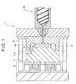
- Fig. 1 is a schematic view showing an injection/compression molding unit 1 in the state where dies 11, 12 are opened and a conductive thermoplastic resin composition 15 is injected and filled therein
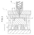
- Fig. 2 is a schematic view showing the dies 11, 12 in the state where the dies 11, 12 are closed and the conductive thermoplastic resin composition 15 is compressed and formed.
- a compression unit 10 For carrying out the injection/compression molding method according to the present invention, as shown in Fig. 1, at first, in the state where a compression unit 10 is retarded, mating faces of the dies 11, 12 are separated and opened to form a cavity space 13 (sometimes described simply as “space 13" hereinafter), and the conductive thermoplastic resin composition 15 is injected and filled in the space 13 from an injection unit 20 ((1) injection filling step).
- the interval of the cavity space 13 formed between mating faces 11a, 12a of the dies 11, 12 is set to the range of 0.5 to 5.0 mm, and more preferably to the range of 3.0 to 5.0 mm.
- the conductive thermoplastic resin composition 15 in the melted state can smoothly be injected and filled, and in addition the interval advantageously functions as a space for compressing in the compression forming step (2), so that the processing for compression forming the composition 15 can smoothly be performed.
- any known heater may be employed for heating the dies 11, 12 before the conductive thermoplastic resin composition 15 is filled therein.
- Further electrically heated bodies may be provided on surfaces of the dies 11, 12 and the electrically heating bodies may be energized, before the resin is filled therein, for heating the dies 11, 12 up to a prespecified temperature.
- the electrically heating body there can be enlisted, for instance, silicon nitrate, titanium nitrate, aluminum nitrate, zirconia oxide and the like.
- a temperature of the dies may be decided according to a type of the conductive thermoplastic resin composition, and generally the temperature is in the range of 150 to about 250 °C. Since the dies are not required to be heated to a high temperature (for instance, in the range of 270 to 300 °C) like that employed in the conventional technology in the molding method according to the present invention, the molded product can smoothly be cooled, and therefore the injection/compression molding process can easily be carried out.
- a heat insulating layer may be provided on a surface of each of the dies 11, 12, and when a heat insulating layer is provided on a surface of each of the dies 11, 12, generation of weld line or sink in the molded product can be prevented.
- the thickness of the heat insulating layer may be in the range of 0.5 to about 3.0 mm. Any of zirconia-based ceramics, refractory polyimide, alumina and the like may be used as a material for the heat insulating layer.
- Such a commercial product ULPAC (registered trademark) die or ULPAC layer (produced by Taiyo Manufacturing Co. Ltd.) may be used.
- the injection filling step (1) when the conductive thermoplastic resin composition 15 is injected and filled in the space 13, it is preferable to take any of the following measures 1 to 3 for improving the dispersibility and adaptability to be formed of the conductive filler contained in the molded product at a relatively high content rate. These measures may be employed one by one or in combination.
- the shear rate in the injection filling step as shown by the Expression (I) or (II) below is set to the range of 5000 to 50000/sec.
- ⁇ a 4 ⁇ Q / ⁇ ⁇ R 3 (Here Q is injection rate (in cc/sec), R is radius of gate (in cm).)
- ⁇ b 6 ⁇ Q / W ⁇ h 2 (Here Q is injection rate (in cc/sec), W is width of gate (in cm), and h is thickness of gate (in cm).)
- the injection ratio Q shown in the Expression (I) and Expression (II) indicates a quantity (volume) of resin injected per unit period of time, and in the injection filling step (1) in the present invention, the injection rate Q is generally to the range of about 80 to about 500 (cc/sec), and the value may be set according to a type of used thermoplastic resin.
- a supercritical fluid is injected into the conductive thermoplastic resin composition 15 in the melted state.
- the supercritical fluid it is preferable to use carbon dioxide gas or nitrogen gas in the supercritical state.
- the supercritical state as used herein indicates the state where a temperature and a pressure are over those allowing coexistence of a gas and a liquid and the density of the gas becomes equal to that of the liquid so that the gas phase and the liquid phase are not differentiated from each other, and a fluid generated in this supercritical state is defined as the supercritical fluid.
- a temperature and a pressure in the supercritical state are a supercritical temperature and a supercritical pressure respectively, and for instance, in a case of carbon dioxide, the supercritical temperature and supercritical pressure are 31 °C and 7.4 MPa respectively.
- the supercritical fluid may be injected into a conductive thermoplastic resin composition at ratio of 0.5 to 3.0 mass%, and for instance, in a cylinder, the supercritical fluid may be injected into the composition in the melted state.
- a chemical foaming agent is added to the conductive thermoplastic resin composition 15.
- the chemical foaming agent is added in the resin composition to plasticize and melt the resin composition, it is preferable to use a chemical foaming agent generating nitrogen gas or carbon dioxide gas when thermally decomposed, and the chemical foaming agent may be dry-blended in the conductive thermoplastic resin composition not having been melted at ratio of 1.0 to about 5.0 mass%.
- the conductive thermoplastic resin composition 15 plasticized and melted in the injection filling step (1) is injected and filled in the space 13 formed between mating faces 11a, 12a of the dies 11, 12.
- the injection/compression molding unit 10 is moved forward to carry out the compression forming step (2) for compression forming the conductive thermoplastic resin composition 15 filled in the closed dies 11, 12.
- the compression forming step (2) is started at the time point when the conductive thermoplastic resin composition 15 has been completely filled, but the step may be start at a different time point when the filling of conductive thermoplastic resin composition 15 is completed (for instance, 0.1 to 0.5 sec before completion of the filling operation).
- the compression speed in the compression forming step (2) is preferably set to the range of 1 to 20 mm/sec and more preferably to the range of 5 to 20 mm/sec.
- the compression speed is set to the range described above, the conductive thermoplastic resin composition 15 injected and filled as described above can be compressed and formed smoothly, but when the compression speed is less than 1 mm/sec, the wall thickness distribution in the obtained molded product may be degraded (for instance, like in a case where the gate side is thick and that in the fluidized end is thin), and the adaptability of the conductive thermoplastic resin composition 15 to an continuous operation for molding may be negatively affected like in a case where a frequency of short shot becomes higher.
- the compression speed is over 20 mm/sec, quality of the molded product is stabilized, but a load to a molding machine or a die is large, and various problems may occur such as that the molding machine is depleted quickly.
- the compression pressure is 10 MPa or higher, and preferably 50 MPa.
- a pressure for clamping the dies in this step is about 60 tons, and preferably about 300 tons.
- the compression pressure is 10 MPa or higher, the material is sufficiently compressed and formed, and a molding body having a good external appearance can be obtained, but when the compression pressure is smaller than 10 MPa, appearance inferiority such as a sink or warpage will generated on the surface of a molded article due to insufficient pressure.
- the compression unit 10 is moved forward as described above, the dies 11, 12 are closed, a die clamping force is loaded thereto to compress and form the conductive thermoplastic resin composition 15 filled therein, and then the dies 11, 12 are cooled to cool and solidify the conductive thermoplastic resin composition 15 inside the dies.
- the cooling temperature is generally in the range of 160 to 250 °C (preferably in the range of 180 to 230 °C), and the cooling period of time should be in the range of 30 to about 90 seconds (preferably in the range of 50 to 70 seconds).
- the compression unit 10 is moved forward as shown in Fig. 2, the dies 11, 12 are closed with the clamping force loaded thereto, and the conductive thermoplastic resin composition 15 in the dies is compressed and formed into a desired form under the compression forming conditions as described below ((2) compression forming step).
- the dies 11, 12 are cooled for 30 to 90 seconds (preferably for 50 to 70 seconds) at a cooling temperature in the range of 160 to 250 °C (preferably in the range of 180 to 230 °C) to cool and solidify the conductive thermoplastic resin composition 15 in the dies.
- a cooling temperature in the range of 160 to 250 °C (preferably in the range of 180 to 230 °C) to cool and solidify the conductive thermoplastic resin composition 15 in the dies.
- the dies 11, 12 are opened, and the solidified composition is taken out, thus a molded product with a desired form being obtained.
- the injection filling step (1) and compression forming step (2) are carried out under prespecified conditions, the fluidity of the conductive thermoplastic resin composition 15 is kept excellent during the molding process, and also the adaptability to be molded is kept good during the process. Because of the features, the molding method allowing for molding of a molded product with a conductive filler contained therein at a high content rate is advantageously provided.
- a conductive filler is homogeneously dispersed in the thermoplastic resin like powder in the injection filling step, and therefore the fluidity of the conductive thermoplastic resin composition 15 in the dies is kept good, and the conductive filler is homogeneously dispersed also in the molded product, and further the excellent appearance is provided.
- thermoplastic resin polyphenylene sulfide
- graphite the conductive filler for preparing the conductive thermoplastic resin composition
- the molded product obtained with the injection/compression molding method according to the present invention contains a conductive filler at a high content rate and the conductive filler is homogeneously distributed in the molded product, so that a molded product applicable to applications requiring high conductivity is provided.
- the molded product according to the present invention can be molded into a desired form, so that the molded product may be used in a wide range, for instance, as a separator for a fuel cell (especially as a separator for a solid polymer type of fuel cell), a resin-made electrode, and an electric circuit.
- Fig. 3 is a general view showing a basic structure of a fuel cell 50 using therein a separator for a fuel cell using a molded product obtained with the injection/compression molding method according to the present invention.
- the fuel cell 50 shown in Fig. 3 includes a fuel electrode 51, a matrix 52, an air electrode 53, and a separator 54 for a fuel cell (sometimes described simply as “separator 54" hereinafter), and a plurality of grooves 55 are formed on both the top and rear surfaces of this separator 54 respectively.
- the plurality of grooves 55 formed on the separator 54 for a fuel cell may be formed in batch simultaneously when the separator 54 is formed with the injection/compression molding method according to the present invention, and in this case, mechanical machining such as drilling is not required, and the separator 54 can be produced with low cost.
- mechanical machining such as drilling is not required, and the separator 54 can be produced with low cost.
- the separator 54 having a specific form is required, sometimes it may be hard to obtain the separator 54 by carrying out the injection/compression molding process once using dies, and in that case, mechanical machining such as cutting, drilling, screw thread cutting, and the like may be performed to the obtained molded product.
- the conductive thermoplastic resin composition 15 comprises a conductive filler and thermoplastic resin, but other fillers may be added to the conductive thermoplastic resin composition 15 on the condition that the effects of the present invention are not spoiled.
- the fillers include, but not limited to, glass fiber, potassium titanate whisker, zinc oxide whisker, aluminum borate whisker; fiber-based fillers such as aramid fiber, alumina fiber, silicon carbonate fiber, ceramic fiber, asbestos fiber, gypsum fiber, and metal fiber; silicates such as wallastenite, zeolite, sericite, kaolin, mica, clay, pyrophyllite, bentonite, asbestos, talc, and alumina silicate; metallic compounds such as alumina, silicon oxide, magnesium oxide, zirconium oxide, titanium oxide, and ferric oxide; carbonates such as calcium carbonate, magnesium carbonate, and dolomite; sulfates such as calcium sulfate, and barium sulfate; hydroxides such as magnesium hydroxide, calcium hydroxide, and aluminum hydroxide; and non fiber-based fillers such as glass beads, glass flake, ceramic beads, boron nitrate, silicon carbonate, and silica, and the materials may be hollow.
- the fiber-based fillers or non fiber-based fillers may be preprocessed with any coupling agent such as isocianate-based compounds, organic silane-based compounds, organic titanate-based compounds, organic borane-based compounds, or epoxy-based compounds prior to use thereof.
- any coupling agent such as isocianate-based compounds, organic silane-based compounds, organic titanate-based compounds, organic borane-based compounds, or epoxy-based compounds prior to use thereof.
- additives including a crystal nucleus agent such as an organic phosphor compound, or polyether ether, a coloring preventing agent such as hyposulfite, an antioxidant such as hindered phenol or hindered amine, UV-ray preventing agent, a coloring agent such as die or pigment, a thermal stabilizer, a lubricant, an antistatic agent, and a plasticizer may be added to the conductive thermoplastic resin composition 15 on the conditions that any negative influence is not given to the effects provided by the present invention.
- a form of the die is accurately reflected to a form of the molded product, and especially dimensional accuracy in the thickness can be improved.
- Any structure and form may be employed for carrying out the present invention on the condition that the effects of the present invention are provided.
- Polyphenylene sulfide (PPS) (IPC-1 produced by Idemitsu Petrochemical Co. Ltd with the viscosity of 7 Pa ⁇ s in the melted state) was used as thermoplastic resin, and graphite (CGC-100H, Japan Graphite Industry Co. Ltd.) as a conductive filler was mixed in the thermoplastic resin at ratio of 82 mass% to obtain a conductive thermoplastic resin composition.
- the fluidity of the conductive thermoplastic resin composition as defined with the spiral flow value at the resin temperature of 320 °C and the die temperature of 135 °C is 60 mm when the wall thickness is 1.0 mm, and 90 mm when the wall thickness is 1.5 mm.
- This conductive thermoplastic resin composition was molded with the injection/compression molding method according to the present invention using the injection/compression molding machine having the injection/compression molding unit as shown in Fig. 1 and Fig. 2 (AZ-7000 produced by Nissei Plastic Industrial Co. Ltd. with the clamping force of 350 tons (3430kN) by carrying out the injection filling step (1) and the compression forming step (2) as described below to obtain a plate-formed molded product (with the size of 200 mm (height) x 300 mm (width) x 1.5 mm (thickness)).
- the used die is the so-called hot runner die, and an outlet diameter of the hot runner was 2.0 mm.
- the gate was a four-point fan gate with the width of 20 mm and the thickness of 2.0 mm, and the gate was formed in the vertical edge side of the plate-like molded product (at the side with the length of 200 mm).
- the die temperature was controlled with a heater to the temperatures (180 °C or 230 °C) shown in Table 1 below.
- the interval between the mating faces of the dies was set to 2.0 mm, and the conductive thermoplastic resin composition in the melted state was filled in the cavity space of the dies so that the wall thickness of an obtained molded product was 1.5 mm.
- the injection rate was adjusted following the following expression (II) in the injection filling step so that the shear rate would be 5100/sec.
- ⁇ b 6 ⁇ Q / W ⁇ h 2 (Here Q is injection rate (in cc/sec), W is width of gate (in cm), and h is thickness of gate (in cm).)
- the compression unit was moved forward to tighten the dies, and then the dies were closed to compress and form the conductive thermoplastic resin composition in the cavity space of the dies at the compression speed of 5.0 mm/sec with the compression pressure of 50 MPa.
- the dies were cooled for about 50 seconds at 180 °C to cool and solidify the conductive thermoplastic resin composition, and when the composition was cooled and solidified, the composition was taken out from the dies to obtain a molded product according to the present invention.
- a plate-formed molded product according to the present invention was obtained using the same method as that described in Example 1 excluding the point that the shear rate was changed from 5100/sec in the injection/compression molding method described in Example 1 to 34400/sec.
- a plate-formed molded product according to the present invention was obtained using the same method as that described in Example 1 excluding the point that the die temperature was changed from 180 °C to 230 °C.
- a plate-formed molded product according to the present invention was obtained using the same method as that described in Example 3 excluding the point that the shear rate was changed from 5100/sec to 34400/sec.
- a plate-formed molded product according to the present invention was obtained using the same method as that described in Example 3 excluding the point that the interval between the dies was changed from 5.0 mm in Example 3 to 2.0 mm.
- a plate-formed molded product according to the present invention was obtained using the same method as that described in Example 3 excluding the point that the compression speed was changed from 5.0 mm/sec in Example 3 to 1.0 mm/sec.
- the molding conditions employed in the injection/compression molding method in Examples 1 to 6 are shown in Table 1.
- Example 1 Die temperature (°C) Interval between dies (mm) Shear rate (/sec) Compression speed (mm/sec) Compression pressure (MPa)
- Example 1 180 5.0 5100 5.0 50
- Example 2 180 5.0 34400 5.0 50
- Example 3 230 5.0 5100 5.0 50
- Example 4 230 5.0 34400 5.0 50
- Example 5 230 2.0 34400 5.0 50
- Example 6 230 5.0 34400 1.0 50
- the wall thickness distribution (A) and the volume resistivity (B) of the plate-formed products obtained in Examples 1 to 6 were measured with the method as described below. A result of measurement is shown in Table 2.
- the wall thickness was measured at two positions on each molded product (in the gate side and at a terminal in the fluidizing section) with a micrometer caliper procurable from the market (1/100 mm) to check the maximum value and the minimum value.
- Table 2 Wall thickness distribution (mm) Volume resistivity (m ⁇ cm) Maximum Minimum Maximum Minimum Example 1 1.78 1.5 20 20 Example 2 1.65 1.53 20 15 Example 3 1.64 1.52 20 15 Example 4 1.51 1.51 15 15 Example 5 1.68 1.57 15 15 Example 6 1.75 1.58 15 15
- the plate-formed molded products according to the present invention obtained by means of the injection/compression molding method in Examples 1 to 6 have the homogeneous wall thickness distribution and excellent volume resistivity respectively.
- Examples 1 to 6 for carrying out the injection/compression molding method according to the present invention, to check the dispersed state of graphite as a conductive filler in the conductive thermoplastic resin composition in the melted state to be injected, the state of resin at an outlet port of the hot runner with the diameter of 2 mm was checked following the so-called hot runner purge, and it was identified in any of Examples 1 to 6 that the conductive filler was homogeneously distributed like powder in the conductive thermoplastic resin composition in the injection process.
- a plate-formed molded product according to the present invention was obtained using the same method as that employed in Example 1 excluding the point that carbon dioxide gas in the supercritical state was injected to the conductive thermoplastic resin composition in the melted state to be injected so that the content rate would be in the range of 0.5 to 3.0 mass% against the total weight of the conductive thermoplastic resin composition in stead of adjusting the shear rate to 5100/sec (keeping the shear rate at 1000/sec) in the injection/compression molding method in Example 1.
- the carbon dioxide gas in the supercritical state was injected into the conductive thermoplastic resin composition in the melted state with a cylinder section of an injection/compression molding machine.
- a plate-formed molded product according to the present invention was obtained by using the same method as that in Example 7 excluding the point that the die temperature was changed from 180 °C employed in the injection/compression molding method in Example 7 to 230 °C.
- a plate-formed molded product according to the present invention was obtained by using the same method as that in Example 8 excluding the point that a chemical foaming agent (polystyrene EB201 (20% master batch including barium diazo carboxylate as an ingredient) produced by Eiwa Chemical Ind. Co. Ltd.) was dry-blended in the conductive thermoplastic resin composition at a content rate of 3 mass% in stead of injecting carbon dioxide gas in the supercritical state.
- a chemical foaming agent polystyrene EB201 (20% master batch including barium diazo carboxylate as an ingredient
- the molding conditions employed in the injection/compression molding methods in Examples 7 to 9 are shown in Table 3.
- the plate-formed molded products according to the present invention obtained with the injection/compression molding methods in Examples 7 to 9 have homogeneous wall thickness distribution and excellent volume resistivity.
- the dispersed state of graphite as a conductive filler dispersed in the conductive thermoplastic resin composition in the melted state to be injected was checked, and it was confirmed in any of Examples 7 to 9 that the conductive filler was dispersed homogeneously like powder in the conductive thermoplastic resin composition when injected.
- a plate-formed molded product according to the present invention was obtained with the same method as that employed in Example 1 excluding the point that a heat insulating layer (ULPAC produced by Taiyo Manufacturing Co. Ltd. (registered trade name; same is true also in the following description)) with the thickness of 2.0 mm was formed on a surface of the used die in the injection/compression molding method described in Example 1.
- ULPAC heat insulating layer
- a plate-formed molded product according to the present invention was obtained with the same method as that employed in Example 2 excluding the point that a heat insulating layer (ULPAC produced by Taiyo Manufacturing Co. Ltd.) with the thickness of 2.0 mm was formed on a surface of the used die in the injection/compression molding method described in Example 2.
- ULPAC heat insulating layer
- a plate-formed molded product according to the present invention was obtained with the same method as that employed in Example 3 excluding the point that a heat insulating layer (ULPAC produced by Taiyo Manufacturing Co. Ltd.) with the thickness of 2.0 mm was formed on a surface of the used die in the injection/compression molding method described in Example 3.
- ULPAC heat insulating layer
- a plate-formed molded product according to the present invention was obtained with the same method as that employed in Example 4 excluding the point that a heat insulating layer (ULPAC produced by Taiyo Manufacturing Co. Ltd.) with the thickness of 2.0 mm was formed on a surface of the used die in the injection/compression molding method described in Example 4.
- ULPAC heat insulating layer
- a plate-formed molded product according to the present invention was obtained with the same method as that employed in Example 5 excluding the point that a heat insulating layer (ULPAC produced by Taiyo Manufacturing Co. Ltd.) with the thickness of 2.0 mm was formed on a surface of the used die in the injection/compression molding method described in Example 5.
- ULPAC heat insulating layer
- a plate-formed molded product according to the present invention was obtained with the same method as that employed in Example 6 excluding the point that a heat insulating layer (ULPAC produced by Taiyo Manufacturing Co. Ltd.) with the thickness of 2.0 mm was formed on a surface of the used die in the injection/compression molding method described in Example 6.
- ULPAC heat insulating layer
- a plate-formed molded product according to the present invention was obtained by the same method as that employed in Example 15 excluding the point that the compression speed was changed from 1.0 mm/sec employed in the injection/compression molding method employed in Example 15 to 5.0 mm/sec and also the thickness of a heat insulating layer was changed from 2.0 in Example 15 to 0.5 mm.
- the molding conditions employed the injection/compression molding methods in Examples 10 to 16 are shown in Table 5.
- Example 10 180 5.0 5100 5.0 50
- Example 11 180 5.0 34400 5.0 50
- Example 12 230 5.0 5100 5.0 50
- Example 13 230 5.0 34400 5.0 50
- Example 14 230 5.0 34400 5.0 50
- Example 15 230 2.0 34400 1.0 50
- Example 16 230 5.0 34400 5.0 50
- Table 6 Wall thickness distribution (mm) Volume resistivity (m ⁇ cm) Maximum Minimum Maximum Minimum Example 10 1.68 1.53 20 20 Example 11 1.55 1.51 20 15 Example 12 1.62 1.51 20 15 Example 13 1.51 1.51 15 15 Example 14 1.65 1.56 20 15 Example 15 1.69 1.58 20 15 Example 16 1.51 1.51 15 15
- the molded products obtained by the injection/compression molding methods employed in Examples 10 to 16 each have the homogeneous wall thickness distribution and also has the excellent volume resistivity.
- dispersed state of graphite as a conductive filler in the conductive thermoplastic resin composition in the melted state to be injected was checked, and it was found in any of Examples 10 to 16 that the conductive filler was homogeneously dispersed like powder in the conductive thermoplastic resin composition when injected.
Landscapes
- Manufacturing & Machinery (AREA)
- Engineering & Computer Science (AREA)
- Mechanical Engineering (AREA)
- Chemical & Material Sciences (AREA)
- Life Sciences & Earth Sciences (AREA)
- Sustainable Energy (AREA)
- Sustainable Development (AREA)
- Chemical Kinetics & Catalysis (AREA)
- Electrochemistry (AREA)
- General Chemical & Material Sciences (AREA)
- Composite Materials (AREA)
- Injection Moulding Of Plastics Or The Like (AREA)
- Fuel Cell (AREA)
- Moulds For Moulding Plastics Or The Like (AREA)
Abstract
Description
- The present invention relates to an injection/compression molding method for a conductive thermoplastic resin composition, the method enabling producing a molded product of conductive thermoplastic resin composition containing a conductive filler at high content rate with the conductive filer homogeneously dispersed therein.
- Recently, from the view point of prevention of environmental contamination and energy saving, a fuel cell attracts attention as a clean power generator generating no waste other than water capable of generating power using a fuel gas containing hydrogen and air containing oxygen and through an electrolytic process, thus the fuel cells for homes and cars have been actively developing. The fuel cell as described above has a high power generation efficiency and causes no environmental contamination, but can provide only a low voltage taken from the unit cell (one fuel cell), so that a layered structure formed by several tens to several hundreds unit cells is used.
- When unit cells are formed into a layered structure, separators are used each as a component capable of providing conductivity to each unit cell and also functioning as a boundary film for separating a fuel gas supplied to each unit cell from air. This separator for a fuel cell as a product should have high conductivity for collecting power from an electrode, and also such characteristics as the gas barrier property, mechanical strength, and anticorrosion property against electrolytes (such as phosphoric acid or sulfuric acid) and ions because of the requirements such as that a flow path for flowing a fuel gas or the like therein or the like is required to be formed on a surface thereof.
- In a process for manufacturing a fuel cell, it is important to obtain a molded product with excellent fluidity of resin in a molding process and having homogeneous thickness. But since fluidity of thermoplastic resin containing a conductive filler such as a carbon powder or the like at a high content rate (for instance, 80 mass% or higher) is extremely low, and the thermoplastic resin is easily cooled, it is difficult to mold the resin. When molding a material poor in moldability, generally a method such as stamping or compression molding is employed, but since a melt press molding machine is used for molding the material, the stamping molding or press molding has the low productivity, and therefore the molding methods as described above are not adapted to mass production.
- Therefore, there has been the strong need for development of a separator for a fuel cell using an injection molding method with high productivity. As the technique as described above, there has been the technique for molding a thermoplastic resin composition such as polyacetal containing, for instance, a pitch-based carbon fiber at ratio of 80 to 98 mass% with various types of molding methods including the injection molding (Refer to, for instance, Patent document 1). Further there has been proposed the technique for molding a separator for a fuel cell using a conductive inorganic material or a resin material by means of the injection molding or compression molding (Refer to, for instance, Patent document 2).
- [Patent document 1]
Japanese Patent Laid-Open Publication No. 2003-82247
[Patent document 2]Japanese Patent Laid-Open Publication No. 2003-242994 - In a case where a separator for a fuel cell is manufactured by molding a resin material containing a conductive filler at a high content rate by means of injection/compression molding method, the conductive filer filled in the resin material is cooled more quickly as compared to thermoplastic resin, so that it is difficult to obtain with the homogeneous wall thickness. For instance, to obtain a molded product having homogeneous wall thickness, when filling resin in a heating/cooling process, it is necessary to heat a die to a very high temperature (for instance, 270 to 300 °C) and then cool the die, and sometimes the process described in Patent document 1 and Patent document 2 as described above can hardly be carried out, therefore it has been difficult to mold a separator for a fuel cell with a conductive filler filled therein at a high content rate.
- An object of the present invention, in view of the circumstances as described above, is to provide an injection/compression molding method for a conductive thermoplastic resin composition, the method enabling producing a molded product of conductive thermoplastic resin composition containing a conductive filler at high content rate with the conductive filer homogeneously dispersed therein by improving the fluidity of the resin composition during the molding process.
- In the injection/compression molding method for a thermoplastic resin composition according to the present invention, a conductive thermoplastic resin composition is molded by means of injection/compression molding, and the method comprises a injection filling step for injection filling a conductive thermoplastic resin composition containing a conductive filler at ratio of 70 to 95 mass% into a cavity space formed by mating faces of dies each having a temperature in the range of 150 to 250 °C, the space between the mating faces of dies being in the range of 0.5 to 5.0 mm; and a compression forming step for compression forming, after the filling step is finished and the die space was closed, the conductive thermoplastic resin composition filled in the space at the compression speed in the range of 1.0 to 20 mm/sec and with the compression pressure of 10 MPa or higher.
- With the injection/compression molding method for conductive thermoplastic resin according to the present invention, conductive thermoplastic resin is molded by means of injection/compression molding through the injection filling step and the compression forming step, and therefore the fluidity of the conductive thermoplastic resin is substantially improved during the molding process, so that also the fluidity of the resin is excellent, and because of this feature there is advantageously provided the method of molding a molded product with a conductive filler filled therein at a high content rate.
- Further when the injection/compression molding method according to the present invention is employed, the shear rate expressed by the following expression (I) or (II) in injecting and filling the conductive thermoplastic resin composition is preferably in the range of 5000 to 50000/sec

(Here Q is injection rate (in cc/sec), R is radius of gate (in cm).) -

(Here Q is injection rate (in cc/sec), W is width of gate (in cm), and h is thickness of gate (in cm).) - With the present invention, because the shear rate expressed by the expression (I) (when a cross section of a gate in a die is circular) or the expression (II) (when a cross section of a gate in a die is rectangular) is within a specific range in the process of injection filling the conductive thermoplastic resin composition, and therefore the conductive filler is homogeneously dispersed like powder in the thermoplastic resin in the injection filling process. Because of this feature, also the fluidity of the thermoplastic resin composition is improved in the die, and further also in the obtained molded product, the conductive filler is homogeneously dispersed, which provides excellent appearance.
- In the injection/compression molding method according to the present invention, a supercritical fluid may be injected into the conductive thermoplastic resin composition to be injected and filled, and also with this operation, the conductive filler is homogeneously dispersed in thermoplastic resin like powder, and therefore the effects described above can advantageously be achieved.
As the supercritical fluid, carbon dioxide gas and/or nitrogen gas in the supercritical state is preferable. - Further in the injection/compression molding method according to the present invention, a chemical foaming agent for generating carbon dioxide and/or nitrogen gas may be added to the conductive thermoplastic resin, and also with this operation, the conductive filler is homogeneously dispersed like powder in the thermoplastic resin in the injecting and filling process, so that the effects described above can advantageously be obtained.
- In the injection/compression molding method according to the present invention, it is preferable to form a heat insulating layer with the thickness from 0.5 to 3.0 mm on a surface of the die described above.
With the present invention as described above, a heat insulating layer with the specified thickness is formed on a surface of a die, so that generation of weld lines or sink mark can advantageously be prevented. - In the injection/compression molding method according to the present invention, the thermoplastic resin is preferably polyphenylene-sulfide (PPS), and the conductive filler is preferably graphite.
In the conductive thermoplastic resin according to the present invention as described above, the thermoplastic resin is polyphenylene-sulfide (PPS), and the conductive filler is graphite, so that a molded product best suited to be used as a separator for a fuel cell can be provided. -
- [FIG.1] Fig. 1 is a view showing an injecting/compression unit of an embodiment for implementing the injection/compression molding method according to the present invention, and is a general view showing a die in the opened state (in the state where injection and filling are performed);
- [FIG.2] Fig. 2 is different from Fig. 1 in that it shows a general view showing the die in the closed state (in the state where compression forming is being carried out); and
- [FIG.3] Fig. 3 is a general view showing a fuel cell using a separator for a fuel cell molded by the injection/compression molding method according to an embodiment of the present invention.
-
- 1...
- injection/compression molding unit
- 11, 12...
- die
- 11a, 12a...
- mating face
- 13...
- cavity space
- 15...
- conductive thermoplastic resin composition
- 20...
- injection unit
- 30...
- gate
- 50...
- fuel cell
- 51...
- fuel electrode (anode)
- 52...
- matrix
- 53...
- air electrode (cathode)
- 54...
- separator for a fuel cell
- 55...
- groove
- In the injection/compression molding method for molding a conductive thermoplastic resin composition according the present invention (sometimes described simply as the "molding method according to the present invention" hereinafter), conductive thermoplastic resin is molded through a specified injection filling step as well as through a compression forming step, and the conductive thermoplastic resin molded product obtained by the molding method according to the present invention (sometimes described simply as "molded product" hereinafter) contains a conductive filler filled therein at a high content rate, and the conductive filler is well dispersed therein, so that the molded product may be applied, for instance, to a separator for a cell.
- As the thermoplastic resin which may be used in the molding method according to the present invention, it is preferable to use a resin material having the heat resistance, waterproof characteristics, and chemical resistance, and there can be enlisted, for instance, polyphenylene sulfide (PPS) resin, acrylonitrile-styrene-butadiene (ABS) resin, polycarbonate (PC) resin, polyphenylene oxide (PPO) resin, polyacetal resin and the like as the material, and one, two of more of the material as described above may be used singly or in combination. In order to carry out the method according to the present invention, it is preferable to use the polyphenylene sulfide (PPS) resin best suited as a material for forming a separator for a fuel cell.
- As the conductive filler, there can be enlisted various types of graphite such as natural graphite, synthetic graphite, and expanded graphite, carbon black, carbon fiber, gas-phase carbon fiber, carbon nanotube, and the like, and one or two or more among the materials may be used singly or in combination. For carrying out the method according to the present invention, it is preferable to use graphite having small electric specific resistance, high electric conductivity, and excellent dispersibility.
A form of the conductive filler is preferably spherical, or powder-like, and may be particles with the average diameter in the range of 10 to 200 µm and the balk specific gravity in the range of 0.15 to 0.90 g/cm3. - The conductive thermoplastic resin composition is formed by mixing this conductive filler with the thermoplastic resin described above. The conductive filler is contained in the thermoplastic resin at a ratio of 70 to 95 mass%, preferably at a ratio of 75 to 85 mass%, and more preferably at a ratio of 80 to 85 mass%.
Since the conductive thermoplastic resin composition used in the method according to the present invention contains a conductive filler at a high content rate, the conductivity thereof is high. By applying the molding method according to the present invention to injection/compression molding of the conductive thermoplastic resin composition as described above, the conductive filler is well dispersed in the molded product. - To obtain a conductive thermoplastic resin composition by mixing or kneading the thermoplastic resin and the conductive filler each other or together, it is preferable to homogeneously mix or knead the materials each other or together with any known mixer or a kneader such as various mixers including a roller, an extruder, a kneader, a banbary mixer, a Henschel mixer, a planetary mixer and the like.
- The method according to the present invention is carried out by molding conductive thermoplastic resin produced by mixing the thermoplastic resin and the conductive filler each other by injection and compressing, and a mode for carrying out the injection/compression molding is described with reference to Fig. 1 and Fig. 2.
- Fig. 1 is a schematic view showing an injection/compression molding unit 1 in the state where dies 11, 12 are opened and a conductive
thermoplastic resin composition 15 is injected and filled therein, while Fig. 2 is a schematic view showing the dies 11, 12 in the state where the dies 11, 12 are closed and the conductivethermoplastic resin composition 15 is compressed and formed. - For carrying out the injection/compression molding method according to the present invention, as shown in Fig. 1, at first, in the state where a
compression unit 10 is retarded, mating faces of the dies 11, 12 are separated and opened to form a cavity space 13 (sometimes described simply as "space 13" hereinafter), and the conductivethermoplastic resin composition 15 is injected and filled in thespace 13 from an injection unit 20 ((1) injection filling step). - When a specified quantity of conductive
thermoplastic resin composition 15 has been injected and filled therein, in the state where thecompression unit 10 is moved forward as shown in Fig. 2 (in the direction indicated by the arrow in Fig. 2), the dies 11, 12 are closed to load a clamping force for the purpose to compress and form the conductivethermoplastic resin composition 15 filled therein, thus a molded product having a specified form being obtained ((2) compression forming step). - In the injection/compression molding method according to the present invention, at first in the injection filling step (1), it is preferable to set the interval of the
cavity space 13 formed between mating faces 11a, 12a of the dies 11, 12 to the range of 0.5 to 5.0 mm, and more preferably to the range of 3.0 to 5.0 mm. By setting the interval to the range as described above, the conductivethermoplastic resin composition 15 in the melted state can smoothly be injected and filled, and in addition the interval advantageously functions as a space for compressing in the compression forming step (2), so that the processing for compression forming thecomposition 15 can smoothly be performed. - There is no specific restriction over a method of heating the dies 11, 12 in the injection filling step (1), and any known heater may be employed for heating the dies 11, 12 before the conductive
thermoplastic resin composition 15 is filled therein.
Further electrically heated bodies may be provided on surfaces of the dies 11, 12 and the electrically heating bodies may be energized, before the resin is filled therein, for heating the dies 11, 12 up to a prespecified temperature. As the electrically heating body, there can be enlisted, for instance, silicon nitrate, titanium nitrate, aluminum nitrate, zirconia oxide and the like. - A temperature of the dies may be decided according to a type of the conductive thermoplastic resin composition, and generally the temperature is in the range of 150 to about 250 °C. Since the dies are not required to be heated to a high temperature (for instance, in the range of 270 to 300 °C) like that employed in the conventional technology in the molding method according to the present invention, the molded product can smoothly be cooled, and therefore the injection/compression molding process can easily be carried out.
- Further a heat insulating layer may be provided on a surface of each of the dies 11, 12, and when a heat insulating layer is provided on a surface of each of the dies 11, 12, generation of weld line or sink in the molded product can be prevented. The thickness of the heat insulating layer may be in the range of 0.5 to about 3.0 mm.
Any of zirconia-based ceramics, refractory polyimide, alumina and the like may be used as a material for the heat insulating layer. Such a commercial product ULPAC (registered trademark) die or ULPAC layer (produced by Taiyo Manufacturing Co. Ltd.) may be used. - In the injection filling step (1), when the conductive
thermoplastic resin composition 15 is injected and filled in thespace 13, it is preferable to take any of the following measures 1 to 3 for improving the dispersibility and adaptability to be formed of the conductive filler contained in the molded product at a relatively high content rate. These measures may be employed one by one or in combination. - In the measure 1 for homogeneously dispersing the conductive filler in a molded product and improving the adaptability to be formed, the shear rate in the injection filling step as shown by the Expression (I) or (II) below is set to the range of 5000 to 50000/sec.
The shear rate γa expressed by the Expression (1) corresponding to a shear rate when a cross section of agate 30 is circular, and the shear rate γb expressed by the Expression (II) corresponding to that when a cross section of thegate 30 is rectangular. -

(Here Q is injection rate (in cc/sec), R is radius of gate (in cm).) -

(Here Q is injection rate (in cc/sec), W is width of gate (in cm), and h is thickness of gate (in cm).) - The injection ratio Q shown in the Expression (I) and Expression (II) indicates a quantity (volume) of resin injected per unit period of time, and in the injection filling step (1) in the present invention, the injection rate Q is generally to the range of about 80 to about 500 (cc/sec), and the value may be set according to a type of used thermoplastic resin.
- In the measure 2, for instance, a supercritical fluid is injected into the conductive
thermoplastic resin composition 15 in the melted state. As the supercritical fluid, it is preferable to use carbon dioxide gas or nitrogen gas in the supercritical state.
The supercritical state as used herein indicates the state where a temperature and a pressure are over those allowing coexistence of a gas and a liquid and the density of the gas becomes equal to that of the liquid so that the gas phase and the liquid phase are not differentiated from each other, and a fluid generated in this supercritical state is defined as the supercritical fluid. A temperature and a pressure in the supercritical state are a supercritical temperature and a supercritical pressure respectively, and for instance, in a case of carbon dioxide, the supercritical temperature and supercritical pressure are 31 °C and 7.4 MPa respectively. The supercritical fluid may be injected into a conductive thermoplastic resin composition at ratio of 0.5 to 3.0 mass%, and for instance, in a cylinder, the supercritical fluid may be injected into the composition in the melted state. - Further in the measure 3, for instance, a chemical foaming agent is added to the conductive
thermoplastic resin composition 15. In a case where the chemical foaming agent is added in the resin composition to plasticize and melt the resin composition, it is preferable to use a chemical foaming agent generating nitrogen gas or carbon dioxide gas when thermally decomposed, and the chemical foaming agent may be dry-blended in the conductive thermoplastic resin composition not having been melted at ratio of 1.0 to about 5.0 mass%. - As described above, the conductive
thermoplastic resin composition 15 plasticized and melted in the injection filling step (1) is injected and filled in thespace 13 formed between mating faces 11a, 12a of the dies 11, 12.
When a prespecified quantity of the conductivethermoplastic resin composition 15 has been injected and filled therein, the injection/compression molding unit 10 is moved forward to carry out the compression forming step (2) for compression forming the conductivethermoplastic resin composition 15 filled in the closed dies 11, 12.
The compression forming step (2) is started at the time point when the conductivethermoplastic resin composition 15 has been completely filled, but the step may be start at a different time point when the filling of conductivethermoplastic resin composition 15 is completed (for instance, 0.1 to 0.5 sec before completion of the filling operation). - When the molding method according to the present invention is carried out, the compression speed in the compression forming step (2) is preferably set to the range of 1 to 20 mm/sec and more preferably to the range of 5 to 20 mm/sec. When the compression speed is set to the range described above, the conductive
thermoplastic resin composition 15 injected and filled as described above can be compressed and formed smoothly, but when the compression speed is less than 1 mm/sec, the wall thickness distribution in the obtained molded product may be degraded (for instance, like in a case where the gate side is thick and that in the fluidized end is thin), and the adaptability of the conductivethermoplastic resin composition 15 to an continuous operation for molding may be negatively affected like in a case where a frequency of short shot becomes higher. On the other hand, when the compression speed is over 20 mm/sec, quality of the molded product is stabilized, but a load to a molding machine or a die is large, and various problems may occur such as that the molding machine is depleted quickly. - Further in the compression forming step (2), the compression pressure is 10 MPa or higher, and preferably 50 MPa. A pressure for clamping the dies in this step is about 60 tons, and preferably about 300 tons. When the compression pressure is 10 MPa or higher, the material is sufficiently compressed and formed, and a molding body having a good external appearance can be obtained, but when the compression pressure is smaller than 10 MPa, appearance inferiority such as a sink or warpage will generated on the surface of a molded article due to insufficient pressure.
- The
compression unit 10 is moved forward as described above, the dies 11, 12 are closed, a die clamping force is loaded thereto to compress and form the conductivethermoplastic resin composition 15 filled therein, and then the dies 11, 12 are cooled to cool and solidify the conductivethermoplastic resin composition 15 inside the dies. There is no specific restriction over the cooling conditions, but the cooling temperature is generally in the range of 160 to 250 °C (preferably in the range of 180 to 230 °C), and the cooling period of time should be in the range of 30 to about 90 seconds (preferably in the range of 50 to 70 seconds).
When the conductivethermoplastic resin composition 15 is sufficiently cooled and solidified, the dies 11, 12 are opened and the molded product is taken out, thus a molded product with a conductive filler homogeneously dispersed therein being obtained. - An representative embodiment of the injection/compression molding method according to the present invention is described with reference to the injection/compression molding unit 1 shown in Fig. 1 and Fig. 2.
At first, in the state where the interval of thespace 13 formed between the mating faces 11a, 12a of the dies 11, 12 is in the range of 0.5 to 5.0 mm as shown in Fig. 1, the conductivethermoplastic resin composition 15 in the melted state is injected and filled in the dies 11, 12 ((1) injection filling step). In this step, by carrying out any of the measures 1 to 3 described above, the conductive filler is homogeneously dispersed like powder in thermoplastic resin in the injection filling step. - After the conductive
thermoplastic resin composition 15 in the melted state is sufficiently filled in the dies in the injection filling step (1), thecompression unit 10 is moved forward as shown in Fig. 2, the dies 11, 12 are closed with the clamping force loaded thereto, and the conductivethermoplastic resin composition 15 in the dies is compressed and formed into a desired form under the compression forming conditions as described below ((2) compression forming step). -
- Compression speed: 1 to 20 mm/sec
- Compression pressure: 10 MPa or higher
- After the compression forming step (2), the dies 11, 12 are cooled for 30 to 90 seconds (preferably for 50 to 70 seconds) at a cooling temperature in the range of 160 to 250 °C (preferably in the range of 180 to 230 °C) to cool and solidify the conductive
thermoplastic resin composition 15 in the dies. When the composition has been solidified, the dies 11, 12 are opened, and the solidified composition is taken out, thus a molded product with a desired form being obtained. - With the injection/compression molding method according to the present invention as described above, the injection filling step (1) and compression forming step (2) are carried out under prespecified conditions, the fluidity of the conductive
thermoplastic resin composition 15 is kept excellent during the molding process, and also the adaptability to be molded is kept good during the process. Because of the features, the molding method allowing for molding of a molded product with a conductive filler contained therein at a high content rate is advantageously provided. - Further by carrying out any of the measures 1 to 3 in the injection filling step (1), a conductive filler is homogeneously dispersed in the thermoplastic resin like powder in the injection filling step, and therefore the fluidity of the conductive
thermoplastic resin composition 15 in the dies is kept good, and the conductive filler is homogeneously dispersed also in the molded product, and further the excellent appearance is provided. - Further, when a heat insulating layer with the thickness in the range of 0.5 to 3.0 mm is formed on a surface of each of the dies 11, 12, generation of weld line and sink in the molded product can advantageously be prevented.
- Further by employing polyphenylene sulfide (PPS) as the thermoplastic resin and graphite as the conductive filler for preparing the conductive
thermoplastic resin composition 15, a molded product best suited to be used as a separator for a fuel cell is provided with this injection/compression molding method. - The molded product obtained with the injection/compression molding method according to the present invention contains a conductive filler at a high content rate and the conductive filler is homogeneously distributed in the molded product, so that a molded product applicable to applications requiring high conductivity is provided. The molded product according to the present invention can be molded into a desired form, so that the molded product may be used in a wide range, for instance, as a separator for a fuel cell (especially as a separator for a solid polymer type of fuel cell), a resin-made electrode, and an electric circuit.
- Fig. 3 is a general view showing a basic structure of a
fuel cell 50 using therein a separator for a fuel cell using a molded product obtained with the injection/compression molding method according to the present invention.
Thefuel cell 50 shown in Fig. 3 includes afuel electrode 51, amatrix 52, anair electrode 53, and aseparator 54 for a fuel cell (sometimes described simply as "separator 54" hereinafter), and a plurality ofgrooves 55 are formed on both the top and rear surfaces of thisseparator 54 respectively. - The plurality of
grooves 55 formed on theseparator 54 for a fuel cell may be formed in batch simultaneously when theseparator 54 is formed with the injection/compression molding method according to the present invention, and in this case, mechanical machining such as drilling is not required, and theseparator 54 can be produced with low cost. When theseparator 54 having a specific form is required, sometimes it may be hard to obtain theseparator 54 by carrying out the injection/compression molding process once using dies, and in that case, mechanical machining such as cutting, drilling, screw thread cutting, and the like may be performed to the obtained molded product. - The embodiment of the present invention described above shows only an aspect of the present invention, and the present invention is not limited to the embodiment described above, and it is needless to say that the modifications and improvements within a range in which the objects and effects of the present invention can be achieved are included within a scope of the present invention. Further for carrying out the present invention, structures and forms other than those described above may be employed within a range in which the objects and effects of the present invention ca be achieved.
- For instance, in the embodiment described above, the conductive
thermoplastic resin composition 15 comprises a conductive filler and thermoplastic resin, but other fillers may be added to the conductivethermoplastic resin composition 15 on the condition that the effects of the present invention are not spoiled. - Specifically the fillers include, but not limited to, glass fiber, potassium titanate whisker, zinc oxide whisker, aluminum borate whisker; fiber-based fillers such as aramid fiber, alumina fiber, silicon carbonate fiber, ceramic fiber, asbestos fiber, gypsum fiber, and metal fiber; silicates such as wallastenite, zeolite, sericite, kaolin, mica, clay, pyrophyllite, bentonite, asbestos, talc, and alumina silicate; metallic compounds such as alumina, silicon oxide, magnesium oxide, zirconium oxide, titanium oxide, and ferric oxide; carbonates such as calcium carbonate, magnesium carbonate, and dolomite; sulfates such as calcium sulfate, and barium sulfate; hydroxides such as magnesium hydroxide, calcium hydroxide, and aluminum hydroxide; and non fiber-based fillers such as glass beads, glass flake, ceramic beads, boron nitrate, silicon carbonate, and silica, and the materials may be hollow. The materials may be used singly respectively or in combination. Further to obtain the more improved mechanical strength, the fiber-based fillers or non fiber-based fillers may be preprocessed with any coupling agent such as isocianate-based compounds, organic silane-based compounds, organic titanate-based compounds, organic borane-based compounds, or epoxy-based compounds prior to use thereof.
- Further any of additives including a crystal nucleus agent such as an organic phosphor compound, or polyether ether, a coloring preventing agent such as hyposulfite, an antioxidant such as hindered phenol or hindered amine, UV-ray preventing agent, a coloring agent such as die or pigment, a thermal stabilizer, a lubricant, an antistatic agent, and a plasticizer may be added to the conductive
thermoplastic resin composition 15 on the conditions that any negative influence is not given to the effects provided by the present invention. - Further forms of the fuel cell 50 (Polymer Electrolyte Fuel Cell) and the
separator 54 shown in Fig. 3 are only examples, and configuration of thefuel cell 50 and a form of theseparator 54 are not limited to those shown in the figure, and any configuration and form may be employed. - To carry out the injection/compression molding method according to the present invention, it is preferable for realizing desirable dimensions of a molded product to design a die by previously estimating sink and the like of the conductive
thermoplastic resin composition 15, and in this case, a form of the die is accurately reflected to a form of the molded product, and especially dimensional accuracy in the thickness can be improved.
Any structure and form may be employed for carrying out the present invention on the condition that the effects of the present invention are provided. - The present invention is described in further details with reference to the examples and comparative examples, but the present invention is not limited to the examples described below.
- Polyphenylene sulfide (PPS) (IPC-1 produced by Idemitsu Petrochemical Co. Ltd with the viscosity of 7 Pa·s in the melted state) was used as thermoplastic resin, and graphite (CGC-100H, Japan Graphite Industry Co. Ltd.) as a conductive filler was mixed in the thermoplastic resin at ratio of 82 mass% to obtain a conductive thermoplastic resin composition.
The fluidity of the conductive thermoplastic resin composition as defined with the spiral flow value at the resin temperature of 320 °C and the die temperature of 135 °C is 60 mm when the wall thickness is 1.0 mm, and 90 mm when the wall thickness is 1.5 mm. - This conductive thermoplastic resin composition was molded with the injection/compression molding method according to the present invention using the injection/compression molding machine having the injection/compression molding unit as shown in Fig. 1 and Fig. 2 (AZ-7000 produced by Nissei Plastic Industrial Co. Ltd. with the clamping force of 350 tons (3430kN) by carrying out the injection filling step (1) and the compression forming step (2) as described below to obtain a plate-formed molded product (with the size of 200 mm (height) x 300 mm (width) x 1.5 mm (thickness)).
The used die is the so-called hot runner die, and an outlet diameter of the hot runner was 2.0 mm. The gate was a four-point fan gate with the width of 20 mm and the thickness of 2.0 mm, and the gate was formed in the vertical edge side of the plate-like molded product (at the side with the length of 200 mm).
The die temperature was controlled with a heater to the temperatures (180 °C or 230 °C) shown in Table 1 below. - In the injection/compression unit shown in Fig, 1, the interval between the mating faces of the dies was set to 2.0 mm, and the conductive thermoplastic resin composition in the melted state was filled in the cavity space of the dies so that the wall thickness of an obtained molded product was 1.5 mm. The injection rate was adjusted following the following expression (II) in the injection filling step so that the shear rate would be 5100/sec.
-

(Here Q is injection rate (in cc/sec), W is width of gate (in cm), and h is thickness of gate (in cm).) - At the time point when the conductive thermoplastic resin composition in the melted state has been filled in the dies in the injection filling step (1) described above, the compression unit was moved forward to tighten the dies, and then the dies were closed to compress and form the conductive thermoplastic resin composition in the cavity space of the dies at the compression speed of 5.0 mm/sec with the compression pressure of 50 MPa.
- After the compression forming step was finished, the dies were cooled for about 50 seconds at 180 °C to cool and solidify the conductive thermoplastic resin composition, and when the composition was cooled and solidified, the composition was taken out from the dies to obtain a molded product according to the present invention.
- In this example, a plate-formed molded product according to the present invention was obtained using the same method as that described in Example 1 excluding the point that the shear rate was changed from 5100/sec in the injection/compression molding method described in Example 1 to 34400/sec.
- In this example, a plate-formed molded product according to the present invention was obtained using the same method as that described in Example 1 excluding the point that the die temperature was changed from 180 °C to 230 °C.
- In this example, a plate-formed molded product according to the present invention was obtained using the same method as that described in Example 3 excluding the point that the shear rate was changed from 5100/sec to 34400/sec.
- In this example, a plate-formed molded product according to the present invention was obtained using the same method as that described in Example 3 excluding the point that the interval between the dies was changed from 5.0 mm in Example 3 to 2.0 mm.
- In this example, a plate-formed molded product according to the present invention was obtained using the same method as that described in Example 3 excluding the point that the compression speed was changed from 5.0 mm/sec in Example 3 to 1.0 mm/sec. The molding conditions employed in the injection/compression molding method in Examples 1 to 6 are shown in Table 1.
-
Table 1 Die temperature (°C) Interval between dies (mm) Shear rate (/sec) Compression speed (mm/sec) Compression pressure (MPa) Example 1 180 5.0 5100 5.0 50 Example 2 180 5.0 34400 5.0 50 Example 3 230 5.0 5100 5.0 50 Example 4 230 5.0 34400 5.0 50 Example 5 230 2.0 34400 5.0 50 Example 6 230 5.0 34400 1.0 50 - The wall thickness distribution (A) and the volume resistivity (B) of the plate-formed products obtained in Examples 1 to 6 were measured with the method as described below. A result of measurement is shown in Table 2.
- The wall thickness was measured at two positions on each molded product (in the gate side and at a terminal in the fluidizing section) with a micrometer caliper procurable from the market (1/100 mm) to check the maximum value and the minimum value.
- Measurement was carried out with a resistivity gauge procurable from the market (Rorester GP/ASP probe (produced by Mitsubishi Chemicals Co. Ltd.) according to JIS K7194 by means of the four probe method to check the maximum value and the minimum value.
-
Table 2 Wall thickness distribution (mm) Volume resistivity (mΩ·cm) Maximum Minimum Maximum Minimum Example 1 1.78 1.5 20 20 Example 2 1.65 1.53 20 15 Example 3 1.64 1.52 20 15 Example 4 1.51 1.51 15 15 Example 5 1.68 1.57 15 15 Example 6 1.75 1.58 15 15 - As understood from the result shown in Table 2, the plate-formed molded products according to the present invention obtained by means of the injection/compression molding method in Examples 1 to 6 have the homogeneous wall thickness distribution and excellent volume resistivity respectively.
In Examples 1 to 6, for carrying out the injection/compression molding method according to the present invention, to check the dispersed state of graphite as a conductive filler in the conductive thermoplastic resin composition in the melted state to be injected, the state of resin at an outlet port of the hot runner with the diameter of 2 mm was checked following the so-called hot runner purge, and it was identified in any of Examples 1 to 6 that the conductive filler was homogeneously distributed like powder in the conductive thermoplastic resin composition in the injection process. - A plate-formed molded product according to the present invention was obtained using the same method as that employed in Example 1 excluding the point that carbon dioxide gas in the supercritical state was injected to the conductive thermoplastic resin composition in the melted state to be injected so that the content rate would be in the range of 0.5 to 3.0 mass% against the total weight of the conductive thermoplastic resin composition in stead of adjusting the shear rate to 5100/sec (keeping the shear rate at 1000/sec) in the injection/compression molding method in Example 1.
The carbon dioxide gas in the supercritical state was injected into the conductive thermoplastic resin composition in the melted state with a cylinder section of an injection/compression molding machine. - A plate-formed molded product according to the present invention was obtained by using the same method as that in Example 7 excluding the point that the die temperature was changed from 180 °C employed in the injection/compression molding method in Example 7 to 230 °C.
- A plate-formed molded product according to the present invention was obtained by using the same method as that in Example 8 excluding the point that a chemical foaming agent (polystyrene EB201 (20% master batch including barium diazo carboxylate as an ingredient) produced by Eiwa Chemical Ind. Co. Ltd.) was dry-blended in the conductive thermoplastic resin composition at a content rate of 3 mass% in stead of injecting carbon dioxide gas in the supercritical state.
The molding conditions employed in the injection/compression molding methods in Examples 7 to 9 are shown in Table 3. -
Table 3 Die temperature (°C) Interval between dies (mm) Improving dispersibility by Compression speed (mm/sec) Compression pressure (MPa) Example 7 180 5.0 injecting supercritical fluid 5.0 50 Example 8 230 5.0 Injecting supercritical fluid 5.0 50 Example 9 230 5.0 Addiing foaming agent 5.0 50 - Measurement was made for the wall thickness distribution (A) and the volume resistivity (B) of the molded products obtained in Examples 7 to 9 with the same method as that employed in Test Example 1. A result of measurement is as shown in Table 4.
-
Table 4 Wall thickness distribution (mm) Volume resistivity (mΩ·cm) Maximum Minimum Maximum Minimum Example 7 1.69 1.58 20 15 Example 8 1.53 1.51 15 15 Example 9 1.62 1.55 20 15 - As understood from the result shown in Table 4, the plate-formed molded products according to the present invention obtained with the injection/compression molding methods in Examples 7 to 9 have homogeneous wall thickness distribution and excellent volume resistivity.
Like in Examples 1 to 6 described above, the dispersed state of graphite as a conductive filler dispersed in the conductive thermoplastic resin composition in the melted state to be injected was checked, and it was confirmed in any of Examples 7 to 9 that the conductive filler was dispersed homogeneously like powder in the conductive thermoplastic resin composition when injected. - A plate-formed molded product according to the present invention was obtained with the same method as that employed in Example 1 excluding the point that a heat insulating layer (ULPAC produced by Taiyo Manufacturing Co. Ltd. (registered trade name; same is true also in the following description)) with the thickness of 2.0 mm was formed on a surface of the used die in the injection/compression molding method described in Example 1.
- A plate-formed molded product according to the present invention was obtained with the same method as that employed in Example 2 excluding the point that a heat insulating layer (ULPAC produced by Taiyo Manufacturing Co. Ltd.) with the thickness of 2.0 mm was formed on a surface of the used die in the injection/compression molding method described in Example 2.
- A plate-formed molded product according to the present invention was obtained with the same method as that employed in Example 3 excluding the point that a heat insulating layer (ULPAC produced by Taiyo Manufacturing Co. Ltd.) with the thickness of 2.0 mm was formed on a surface of the used die in the injection/compression molding method described in Example 3.
- A plate-formed molded product according to the present invention was obtained with the same method as that employed in Example 4 excluding the point that a heat insulating layer (ULPAC produced by Taiyo Manufacturing Co. Ltd.) with the thickness of 2.0 mm was formed on a surface of the used die in the injection/compression molding method described in Example 4.
- A plate-formed molded product according to the present invention was obtained with the same method as that employed in Example 5 excluding the point that a heat insulating layer (ULPAC produced by Taiyo Manufacturing Co. Ltd.) with the thickness of 2.0 mm was formed on a surface of the used die in the injection/compression molding method described in Example 5.
- A plate-formed molded product according to the present invention was obtained with the same method as that employed in Example 6 excluding the point that a heat insulating layer (ULPAC produced by Taiyo Manufacturing Co. Ltd.) with the thickness of 2.0 mm was formed on a surface of the used die in the injection/compression molding method described in Example 6.
- A plate-formed molded product according to the present invention was obtained by the same method as that employed in Example 15 excluding the point that the compression speed was changed from 1.0 mm/sec employed in the injection/compression molding method employed in Example 15 to 5.0 mm/sec and also the thickness of a heat insulating layer was changed from 2.0 in Example 15 to 0.5 mm.
The molding conditions employed the injection/compression molding methods in Examples 10 to 16 are shown in Table 5. -
Table 5 Die temperature (°C) Interval between dies (mm) Shear rate (/sec) Compression speed (mm/sec) Compression pressure (MPa) Example 10 180 5.0 5100 5.0 50 Example 11 180 5.0 34400 5.0 50 Example 12 230 5.0 5100 5.0 50 Example 13 230 5.0 34400 5.0 50 Example 14 230 5.0 34400 5.0 50 Example 15 230 2.0 34400 1.0 50 Example 16 230 5.0 34400 5.0 50 - Measurement was made for the wall thickness distribution (A) and volume resistivity (B) of the molded products obtained in Examples 10 to 16 by the same method as that employed in Test Example 1. A result is shown in Table 6.
-
Table 6 Wall thickness distribution (mm) Volume resistivity (mΩ·cm) Maximum Minimum Maximum Minimum Example 10 1.68 1.53 20 20 Example 11 1.55 1.51 20 15 Example 12 1.62 1.51 20 15 Example 13 1.51 1.51 15 15 Example 14 1.65 1.56 20 15 Example 15 1.69 1.58 20 15 Example 16 1.51 1.51 15 15 - As understood from the result shown in Table 6, , the molded products obtained by the injection/compression molding methods employed in Examples 10 to 16 each have the homogeneous wall thickness distribution and also has the excellent volume resistivity.
Like in Examples 1 to 9, dispersed state of graphite as a conductive filler in the conductive thermoplastic resin composition in the melted state to be injected was checked, and it was found in any of Examples 10 to 16 that the conductive filler was homogeneously dispersed like powder in the conductive thermoplastic resin composition when injected. - From the result described above, it was confirmed that, by using the injection/compression molding method according to the present invention employed in each of Examples 1 to 16, plate-formed molded products each having the homogeneous wall thickness distribution, containing the conductive filler homogeneously distributed therein at a high content rate could be obtained. The plate-formed molded products may be used, for instance, as a separator for a fuel cell in a wide range.
[INDUSTRIAL APPLICABILITY]
The injection/compression molding method for molding a conductive thermoplastic resin composition and the conductive thermoplastic resin molded product according to the present invention can be used, for example, as an injection/compression molding method for producing a separator for a cell.
Claims (8)
- A method of molding a conductive thermoplastic resin composition by means of injection/compression molding, comprising:a injection filling step for injection filling a conductive thermoplastic resin composition containing a conductive filler at a ratio of 70 to 95 mass% into a cavity space formed by mating faces of dies each having a temperature in the range of 150 to 250 °C, the space between the mating faces of dies being in the range of 0.5 to 5.0 mm; anda compression forming step for compression forming, after the filling step is finished and the die space was closed, the conductive thermoplastic resin composition filled in said space at a compression speed in the range of 1.0 to 20 mm/sec with the compression pressure of 20 MPa or higher.
- The injection/compression molding method according to claim 1,
wherein the shear rate expressed by the following expression (I) when said conductive thermoplastic resin composition is injected and filled is in the range of 5000 to 50000/sec:
(Here Q is injection rate (in cc/sec). R is radius of gate (in cm).) - The injection/compression molding method according to claim 1,
wherein the shear rate expressed by the following expression (II) when said conductive thermoplastic resin composition is injected and filled is in the range of 5000 to 50000/sec:
(Here Q is injection rate (in cc/sec), W is width of gate (in cm), and h is thickness of gate (in cm).) - The injection/compression molding method according to claim 1,
wherein a supercritical fluid is injected into a molten conductive thermoplastic resin composition to be injected and filled. - The injection/compression molding method according to claim 4,
wherein said supercritical fluid is carbon diode gas in the supercritical state and/or nitrogen gas in the supercritical state. - The injection/compression molding method according to claim 1,
wherein a chemical foaming agent capable of generating carbon dioxide gas and/or nitrogen gas is added to said conductive thermoplastic resin composition. - The injection/compression molding method according to any of claims 1 to 6,
wherein a heat insulating layer with the thickness in the range of 0.5 to 3.0 mm is formed on a surface of said die. - The injection/compression molding method according to any of claims 1 to 7,
wherein said thermoplastic resin is polyphenylene sulfide (PPS), and said conductive filler is graphite.
Applications Claiming Priority (2)
| Application Number | Priority Date | Filing Date | Title |
|---|---|---|---|
| JP2004120449A JP4580676B2 (en) | 2004-04-15 | 2004-04-15 | Method for injection compression molding of conductive thermoplastic resin composition |
| PCT/JP2005/007148 WO2005099994A1 (en) | 2004-04-15 | 2005-04-13 | Method for injection compression molding of conductive thermoplastic resin composition |
Publications (3)
| Publication Number | Publication Date |
|---|---|
| EP1736295A1 true EP1736295A1 (en) | 2006-12-27 |
| EP1736295A8 EP1736295A8 (en) | 2007-02-28 |
| EP1736295A4 EP1736295A4 (en) | 2008-10-29 |
Family
ID=35149848
Family Applications (1)
| Application Number | Title | Priority Date | Filing Date |
|---|---|---|---|
| EP05730433A Withdrawn EP1736295A4 (en) | 2004-04-15 | 2005-04-13 | METHOD FOR INJECTION COMPRESSION MOLDING OF A CONDUCTIVE THERMOPLASTIC RESIN COMPOSITION |
Country Status (7)
| Country | Link |
|---|---|
| EP (1) | EP1736295A4 (en) |
| JP (1) | JP4580676B2 (en) |
| KR (1) | KR101181107B1 (en) |
| CN (1) | CN1942300B (en) |
| MY (1) | MY141178A (en) |
| TW (1) | TWI336655B (en) |
| WO (1) | WO2005099994A1 (en) |
Cited By (3)
| Publication number | Priority date | Publication date | Assignee | Title |
|---|---|---|---|---|
| WO2011157528A1 (en) * | 2010-06-14 | 2011-12-22 | Nv Bekaert Sa | Use of a foaming agent to improve emi shielding |
| JP2016144892A (en) * | 2015-02-06 | 2016-08-12 | マツダ株式会社 | Injection molding apparatus and injection molding method |
| WO2016178703A1 (en) * | 2015-05-01 | 2016-11-10 | Integral Technologies, Inc. | Bipolar plate and method of making and using same |
Families Citing this family (12)
| Publication number | Priority date | Publication date | Assignee | Title |
|---|---|---|---|---|
| KR100869175B1 (en) * | 2007-07-04 | 2008-11-21 | 송영록 | Mold and method for manufacturing filter plate |
| JP2011056753A (en) * | 2009-09-09 | 2011-03-24 | Polyplastics Co | Method for producing injection molded product |
| CN103963318B (en) * | 2013-01-29 | 2019-08-09 | 康廷南拓结构塑料有限公司 | Vacuum forming method for thermosetting sheet products |
| CN103178272B (en) * | 2013-03-13 | 2015-09-30 | 南通百应能源有限公司 | Microcosmic three-dimensional fuel cell membrane electrode manufacture method and particular manufacturing craft thereof |
| JP6400446B2 (en) * | 2014-11-28 | 2018-10-03 | Towa株式会社 | Method for manufacturing plate-like member with protruding electrode, plate-like member with protruding electrode, method for manufacturing electronic component, and electronic component |
| JP6838865B2 (en) * | 2016-03-31 | 2021-03-03 | 宇部興産機械株式会社 | Injection molding equipment and injection molding method |
| JP6979388B2 (en) * | 2018-04-27 | 2021-12-15 | ポリプラスチックス株式会社 | Manufacturing method of antistatic molded product |
| WO2021223947A1 (en) * | 2020-05-08 | 2021-11-11 | Covestro Deutschland Ag | Thermoplastic resin substrate for curved mirror and method for preparing the same |
| CN112140444B (en) * | 2020-08-11 | 2022-10-25 | 华南理工大学 | Preparation method and application of ABS microporous conductive composite material product with multilayer structure |
| CN112895382A (en) * | 2021-01-20 | 2021-06-04 | 宁波哲能精密塑料有限公司 | Heat-insulating gasket and application thereof in extrusion of ultrahigh-temperature engineering plastic |
| CN113980415A (en) * | 2021-11-15 | 2022-01-28 | 成都先进金属材料产业技术研究院股份有限公司 | ABS (acrylonitrile butadiene styrene) resin-based conductive plastic for all-vanadium redox flow battery and preparation method thereof |
| CH719959A1 (en) * | 2022-08-12 | 2024-02-29 | Tosa Swisstech | Bipolar plate for fuel cell and its manufacturing process. |
Family Cites Families (12)
| Publication number | Priority date | Publication date | Assignee | Title |
|---|---|---|---|---|
| EP0639439A3 (en) * | 1993-08-17 | 1995-12-13 | Gen Electric | Method and apparatus for molding thermoplastic materials employing molds with void free insulating layer. |
| JP3357229B2 (en) * | 1994-09-08 | 2002-12-16 | 出光石油化学株式会社 | Manufacturing method of laminated molded product and airflow control valve of automotive air conditioner |
| US5993719A (en) * | 1994-09-08 | 1999-11-30 | Idemitsu Petrochemical Co., Ltd. | Method of producing a laminated molding |
| GB0030182D0 (en) * | 2000-12-11 | 2001-01-24 | Univ Brunel | Material processing |
| JP2003242994A (en) * | 2002-02-13 | 2003-08-29 | Matsushita Electric Ind Co Ltd | Method for producing fuel cell separator and polymer electrolyte fuel cell using the same |
| US20020197523A1 (en) * | 2001-06-13 | 2002-12-26 | Matsushita Electric Industrial Co., Ltd | Method of producing fuel cell and fuel cell |
| JP2003082247A (en) * | 2001-06-28 | 2003-03-19 | Toray Ind Inc | Thermoplastic resin composition and molded article |
| JP4899270B2 (en) * | 2001-08-09 | 2012-03-21 | 東レ株式会社 | Polyphenylene sulfide resin foam molding |
| CN100471913C (en) * | 2002-03-18 | 2009-03-25 | Ntn株式会社 | Conductive resin molded products |
| JP2004160772A (en) * | 2002-11-12 | 2004-06-10 | Meiki Co Ltd | Method of forming fuel cell separator |
| JP2004167777A (en) * | 2002-11-19 | 2004-06-17 | Hitachi Maxell Ltd | Thermoplastic foam and method and apparatus for producing the same |
| JP2004263026A (en) * | 2003-02-28 | 2004-09-24 | Dainippon Ink & Chem Inc | Conductive polyarylene sulfide resin composition and separator for fuel cell |
-
2004
- 2004-04-15 JP JP2004120449A patent/JP4580676B2/en not_active Expired - Fee Related
-
2005
- 2005-04-13 KR KR1020067021337A patent/KR101181107B1/en not_active Expired - Fee Related
- 2005-04-13 CN CN2005800113992A patent/CN1942300B/en not_active Expired - Fee Related
- 2005-04-13 WO PCT/JP2005/007148 patent/WO2005099994A1/en not_active Ceased
- 2005-04-13 EP EP05730433A patent/EP1736295A4/en not_active Withdrawn
- 2005-04-14 TW TW094111901A patent/TWI336655B/en not_active IP Right Cessation
- 2005-04-15 MY MYPI20051672A patent/MY141178A/en unknown
Cited By (6)
| Publication number | Priority date | Publication date | Assignee | Title |
|---|---|---|---|---|
| WO2011157528A1 (en) * | 2010-06-14 | 2011-12-22 | Nv Bekaert Sa | Use of a foaming agent to improve emi shielding |
| BE1020350A3 (en) * | 2010-06-14 | 2013-08-06 | Bekaert Sa Nv | USE OF A FOAM TO IMPROVE ELECTROMAGNETIC PROTECTION |
| US8858848B2 (en) | 2010-06-14 | 2014-10-14 | Nv Bekaert Sa | Foaming agent to improve EMI shielding |
| JP2016144892A (en) * | 2015-02-06 | 2016-08-12 | マツダ株式会社 | Injection molding apparatus and injection molding method |
| WO2016178703A1 (en) * | 2015-05-01 | 2016-11-10 | Integral Technologies, Inc. | Bipolar plate and method of making and using same |
| US10804540B2 (en) | 2015-05-01 | 2020-10-13 | Pivotal Battery Corp | Bipolar plate and method of making and using same |
Also Published As
| Publication number | Publication date |
|---|---|
| TWI336655B (en) | 2011-02-01 |
| EP1736295A8 (en) | 2007-02-28 |
| CN1942300A (en) | 2007-04-04 |
| EP1736295A4 (en) | 2008-10-29 |
| KR20070004839A (en) | 2007-01-09 |
| MY141178A (en) | 2010-03-31 |
| CN1942300B (en) | 2010-11-24 |
| KR101181107B1 (en) | 2012-09-07 |
| TW200606007A (en) | 2006-02-16 |
| JP2005297486A (en) | 2005-10-27 |
| WO2005099994A1 (en) | 2005-10-27 |
| JP4580676B2 (en) | 2010-11-17 |
Similar Documents
| Publication | Publication Date | Title |
|---|---|---|
| JP4590414B2 (en) | Injection compression molding method | |
| JP4580676B2 (en) | Method for injection compression molding of conductive thermoplastic resin composition | |
| US20020039675A1 (en) | Compounding and molding process for fuel cell collector plates | |
| EP2065956B1 (en) | Conductive resin molding for a fuel cell separator | |
| CN1326598A (en) | Compounding and molding process for fuel cell collector plates | |
| EP1280217A2 (en) | Fuel-cell separator, production of the same, and fuel cell | |
| US6949305B2 (en) | Separator for fuel cell, method for producing separator and fuel cell applied with separator | |
| EP3498667A1 (en) | Powder composition comprising first and second agglomerates of inorganic particles and polymer composition comprising a polymer and the powder composition | |
| JP2006019227A (en) | Polyphenylene sulfide (PPS) resin composition, fuel cell separator, fuel cell, and method for producing fuel cell separator | |
| EP1965457A1 (en) | Separator material for fuel cell and process for producing the same | |
| CN100584575C (en) | Injection Compression Molding Method | |
| JPH081663A (en) | Production of molding pellet of highly filled compound | |
| JP4733008B2 (en) | Conductive resin molded body and method for producing the same | |
| JP4192525B2 (en) | Manufacturing method of fuel cell separator | |
| JP2004122367A (en) | Insert molded body and method of manufacturing the same | |
| JP4515140B2 (en) | Method for injection compression molding of conductive structure | |
| CN119943985A (en) | A composite bipolar plate with a multi-scale conductive network and easy thermoforming | |
| JP2008255256A (en) | Method of manufacturing resin molded object | |
| JP2007126593A (en) | Resin composite material-molded article, separator and method for producing the same | |
| CN105633419A (en) | Bipolar plate used for hydrogen fuel battery pack and manufacturing process therefor | |
| JP2007145023A (en) | Electric-conductive resin molded article and its production method | |
| MXPA01004992A (en) | Compounding and molding process for fuel cell collector plates | |
| JP2004152589A (en) | Method for manufacturing fuel cell separator |
Legal Events
| Date | Code | Title | Description |
|---|---|---|---|
| PUAI | Public reference made under article 153(3) epc to a published international application that has entered the european phase |
Free format text: ORIGINAL CODE: 0009012 |
|
| 17P | Request for examination filed |
Effective date: 20061012 |
|
| AK | Designated contracting states |
Kind code of ref document: A1 Designated state(s): AT BE BG CH CY CZ DE DK EE ES FI FR GB GR HU IE IS IT LI LT LU MC NL PL PT RO SE SI SK TR |
|
| RIN1 | Information on inventor provided before grant (corrected) |
Inventor name: AE, HARUHIKO Inventor name: IGA, TORU Inventor name: TANAKA, TAKAYOSHI |
|
| DAX | Request for extension of the european patent (deleted) | ||
| A4 | Supplementary search report drawn up and despatched |
Effective date: 20080926 |
|
| 17Q | First examination report despatched |
Effective date: 20100408 |
|
| STAA | Information on the status of an ep patent application or granted ep patent |
Free format text: STATUS: THE APPLICATION IS DEEMED TO BE WITHDRAWN |
|
| 18D | Application deemed to be withdrawn |
Effective date: 20110615 |