EP1736126A1 - Method of continuously making disposable diaper - Google Patents
Method of continuously making disposable diaper Download PDFInfo
- Publication number
- EP1736126A1 EP1736126A1 EP05728448A EP05728448A EP1736126A1 EP 1736126 A1 EP1736126 A1 EP 1736126A1 EP 05728448 A EP05728448 A EP 05728448A EP 05728448 A EP05728448 A EP 05728448A EP 1736126 A1 EP1736126 A1 EP 1736126A1
- Authority
- EP
- European Patent Office
- Prior art keywords
- body fluid
- liquid
- fluid absorbent
- continuous
- machine direction
- Prior art date
- Legal status (The legal status is an assumption and is not a legal conclusion. Google has not performed a legal analysis and makes no representation as to the accuracy of the status listed.)
- Withdrawn
Links
Images


Classifications
-
- A—HUMAN NECESSITIES
- A61—MEDICAL OR VETERINARY SCIENCE; HYGIENE
- A61F—FILTERS IMPLANTABLE INTO BLOOD VESSELS; PROSTHESES; DEVICES PROVIDING PATENCY TO, OR PREVENTING COLLAPSING OF, TUBULAR STRUCTURES OF THE BODY, e.g. STENTS; ORTHOPAEDIC, NURSING OR CONTRACEPTIVE DEVICES; FOMENTATION; TREATMENT OR PROTECTION OF EYES OR EARS; BANDAGES, DRESSINGS OR ABSORBENT PADS; FIRST-AID KITS
- A61F13/00—Bandages or dressings; Absorbent pads
- A61F13/15—Absorbent pads, e.g. sanitary towels, swabs or tampons for external or internal application to the body; Supporting or fastening means therefor; Tampon applicators
- A61F13/45—Absorbent pads, e.g. sanitary towels, swabs or tampons for external or internal application to the body; Supporting or fastening means therefor; Tampon applicators characterised by the shape
- A61F13/49—Absorbent articles specially adapted to be worn around the waist, e.g. diapers
- A61F13/495—Absorbent articles specially adapted to be worn around the waist, e.g. diapers with faecal cavity
-
- A—HUMAN NECESSITIES
- A61—MEDICAL OR VETERINARY SCIENCE; HYGIENE
- A61F—FILTERS IMPLANTABLE INTO BLOOD VESSELS; PROSTHESES; DEVICES PROVIDING PATENCY TO, OR PREVENTING COLLAPSING OF, TUBULAR STRUCTURES OF THE BODY, e.g. STENTS; ORTHOPAEDIC, NURSING OR CONTRACEPTIVE DEVICES; FOMENTATION; TREATMENT OR PROTECTION OF EYES OR EARS; BANDAGES, DRESSINGS OR ABSORBENT PADS; FIRST-AID KITS
- A61F13/00—Bandages or dressings; Absorbent pads
- A61F13/15—Absorbent pads, e.g. sanitary towels, swabs or tampons for external or internal application to the body; Supporting or fastening means therefor; Tampon applicators
- A61F13/15577—Apparatus or processes for manufacturing
- A61F13/15699—Forming webs by bringing together several webs, e.g. by laminating or folding several webs, with or without additional treatment of the webs
-
- A—HUMAN NECESSITIES
- A61—MEDICAL OR VETERINARY SCIENCE; HYGIENE
- A61F—FILTERS IMPLANTABLE INTO BLOOD VESSELS; PROSTHESES; DEVICES PROVIDING PATENCY TO, OR PREVENTING COLLAPSING OF, TUBULAR STRUCTURES OF THE BODY, e.g. STENTS; ORTHOPAEDIC, NURSING OR CONTRACEPTIVE DEVICES; FOMENTATION; TREATMENT OR PROTECTION OF EYES OR EARS; BANDAGES, DRESSINGS OR ABSORBENT PADS; FIRST-AID KITS
- A61F13/00—Bandages or dressings; Absorbent pads
- A61F13/15—Absorbent pads, e.g. sanitary towels, swabs or tampons for external or internal application to the body; Supporting or fastening means therefor; Tampon applicators
- A61F13/15577—Apparatus or processes for manufacturing
- A61F13/15804—Plant, e.g. involving several steps
-
- Y—GENERAL TAGGING OF NEW TECHNOLOGICAL DEVELOPMENTS; GENERAL TAGGING OF CROSS-SECTIONAL TECHNOLOGIES SPANNING OVER SEVERAL SECTIONS OF THE IPC; TECHNICAL SUBJECTS COVERED BY FORMER USPC CROSS-REFERENCE ART COLLECTIONS [XRACs] AND DIGESTS
- Y10—TECHNICAL SUBJECTS COVERED BY FORMER USPC
- Y10T—TECHNICAL SUBJECTS COVERED BY FORMER US CLASSIFICATION
- Y10T156/00—Adhesive bonding and miscellaneous chemical manufacture
- Y10T156/10—Methods of surface bonding and/or assembly therefor
- Y10T156/1052—Methods of surface bonding and/or assembly therefor with cutting, punching, tearing or severing
- Y10T156/1084—Methods of surface bonding and/or assembly therefor with cutting, punching, tearing or severing of continuous or running length bonded web
-
- Y—GENERAL TAGGING OF NEW TECHNOLOGICAL DEVELOPMENTS; GENERAL TAGGING OF CROSS-SECTIONAL TECHNOLOGIES SPANNING OVER SEVERAL SECTIONS OF THE IPC; TECHNICAL SUBJECTS COVERED BY FORMER USPC CROSS-REFERENCE ART COLLECTIONS [XRACs] AND DIGESTS
- Y10—TECHNICAL SUBJECTS COVERED BY FORMER USPC
- Y10T—TECHNICAL SUBJECTS COVERED BY FORMER US CLASSIFICATION
- Y10T156/00—Adhesive bonding and miscellaneous chemical manufacture
- Y10T156/10—Methods of surface bonding and/or assembly therefor
- Y10T156/1089—Methods of surface bonding and/or assembly therefor of discrete laminae to single face of additional lamina
- Y10T156/1092—All laminae planar and face to face
- Y10T156/1093—All laminae planar and face to face with covering of discrete laminae with additional lamina
- Y10T156/1095—Opposed laminae are running length webs
Definitions
- This invention relates to a method for continuously making disposable diaper, more particularly disposable diaper formed with a feces retaining pocket.
- a relatively small panel comprising a body fluid absorbent second core covered with a liquid-pervious sheet is formed so as to overlap the front waist region and a part of the crotch region on the side of the inner surface of the diaper.
- This relatively small panel covers a part of the feces retaining depression of the relatively large panel in the crotch region so that a pocket opening toward the rear waist region is defined between these relatively large and small panels. Feces flowing from the rear waist region toward the crotch region is reliably received.
- PATENT DOCUMENT 1 Japanese Unexamined Patent Application Publication No. 2002-315778
- a method for continuously making a disposable diaper according to the first aspect of the invention comprises the steps of:
- the first machine direction and the second machine direction coincide with a transverse direction of the liquid-impervious sheet while the fourth machine direction coincides with the longitudinal direction of the liquid-impervious sheet and the first composite is placed upon the first liquid-impervious sheet after the first composite has been turned by an angle of 90°.
- the method of this manner facilitates the elastic members continuously extending in the transverse direction to be attached to the diaper because the transverse direction of the diaper coincides with the first and second machine directions.
- the step (6) is followed by the step (7) in which the second continuous assembly placed upon the first continuous assembly is partially folded back along folding guide lines extending in parallel to the second machine direction so that the second liquid-pervious sheet may overlap itself and the second nonwoven fabric web constituting the second continuous assembly may face the continuous cuffs and, in the step (13), the second side edges of said continuous cuffs are partially bonded to the second nonwoven fabric web instead of the second liquid-pervious sheet.
- the method of this manner allows the continuous cuffs to be bonded to the second nonwoven fabric web cooperating with the second liquid-pervious sheet to sandwich the second cores.
- the method further includes a step of attaching, in stretched state, continuous spacer made of belt-like elastic material as second one of the spacing means functioning to reduce a width of the diaper in the crotch region thereby to space the first and second body fluid absorbent panels from each other to the first or second continuous assembly.
- the method of this manner allows the continuous cuffs as well as the continuous spacer as the means serving to reduce the width of the diaper.
- a method for continuously making a disposable diaper according to the second aspect of the invention as defined by Claim 9 comprises the steps of:
- the second spacing means to space the first and second body fluid absorbent panels from each other can be obtained by the step of bonding the continuous spacer made of belt-like elastic material, in stretched state, to the first continuous assembly or to the second continuous assembly so as to straddle the first cores or the second cores.
- the first liquid-impervious sheet comprises liquid-impervious plastic film and a nonwoven fabric layer laminated on at least one of inner and outer surfaces of the film.
- the diaper made in this manner advantageously provides the diaper wearer with comfortable cloth-like touch.
- the first machine direction and the second machine direction coincide with a transverse direction of the liquid-impervious sheet while the fourth machine direction coincides with the longitudinal direction of the liquid-impervious sheet and the first composite is placed upon the first liquid-impervious sheet after the first composite has been turned by an angle of 90°.
- the method of this manner facilitates the elastic members continuously extending in the transverse direction to be attached to the diaper because the transverse direction of the diaper coincides with the first and second machine directions.
- the first machine direction and the second machine direction coincide with the longitudinal direction of the liquid-impervious sheet.
- the first machine direction coincides with the longitudinal direction of the liquid-impervious sheet while the second machine direction coincides with the transverse direction of the liquid-impervious sheet and the method further include a step of turning the first body fluid absorbent panel obtained by cutting the first continuous assembly or the second body fluid absorbent panel obtained by cutting the second continuous assembly by an angle of 90°.
- the method of this manner facilitates the elastic members extending in the transverse direction of the diaper to be continuously fed and attached to the second nonwoven fabric web.
- the method further includes a step of bonding a pair of continuous leak-barrier cuffs each having first and second side edges extending in parallel to each other, the second side edges made of belt-like material being elastically stretch- and contractible in a longitudinal direction thereof, along the first side edges to the fourth continuous assembly with the second side edges being stretched, in the vicinity of the first and second edges of the first composites attached to the fourth continuous assembly.
- the continuous cuffs can be linearly fed in the fourth machine direction and attached to the fourth continuous assembly running in the fourth machine direction.
- the method further includes a step of partially bonding the continuous cuffs to any one of the second liquid-pervious sheet and the second nonwoven fabric web sandwiching the second cores.
- the method of this manner allows the leak-barrier cuffs to function as the additional means to space the first and second body fluid absorbent panels of the diaper from each other.
- a method for continuously making a disposable diaper according to the invention on the third aspect as defined by Claim 16 comprises the steps of:
- the first and/or second means to space the second body fluid absorbent panel from the first body fluid absorbent panel can be obtained by at least one of substeps of bonding, in each section of the continuously fed liquid-impervious sheet allocated for the crotch region, portions of the inner side edges of the leak-barrier cuff members in stretched state to the portions of the second body fluid absorbent panel covered with the portions of the inner side edges; and attaching, in each section of the continuously fed liquid-impervious sheet allocated for the crotch region, a belt-like elastic spacer transversely extending in stretched state between the first and second body fluid absorbent panels to the side edges of at least one of the first and second body fluid absorbent panels.
- Fig. 1 is a perspective view showing a disposable diaper 1 obtained by the inventive method.
- the diaper 1 has an inner surface 1a facing the diaper wearer's skin and an outer surface 1b facing away from the wearer's skin.
- the diaper 1 has a longitudinal direction, a transverse direction and a thickness direction being orthogonal one to another as indicated by double-headed arrows A, B and C, respectively.
- the longitudinal direction A can be referred to also as the back-and-forth direction of the diaper 1 and the transverse direction can be referred to also as the width direction of the diaper 1.
- a rectangular panel-like component 2 which is relatively long in the longitudinal direction A comprises a front waist region 3, a rear waist region 4 and a crotch region 5 extending between these two waist regions 3, 4 and is contoured by a pair of transversely opposite side edges 6 extending in parallel to each other in the longitudinal direction A and a pair of longitudinally opposite ends extending in parallel to each other in the transverse direction B.
- the panel-like component 2 further comprises a liquid-impervious liner sheet 10 which is, in turn, provided on its inner surface with first and second body fluid absorbent panels 11, 12. These panels 11, 12 are partially covered with a pair of leak-barrier cuffs 13, respectively, extending in the longitudinal direction A long the respective side edges 6 of the panel-like component 2.
- Each of these leak-barrier cuffs 13 has a front end 16, a rear end 17, an inner side edge 18 and an outer side edge 19 wherein the front and rear ends 16, 17 as well as the outer side edge 19 are bonded to the liner sheet 10.
- An elastic member 21 is attached in stretched state to the inner side edge 18.
- the panel-like component 2 is further provided in the rear waist region 4 with a waist elastic member 20 attached in stretched state thereto and provided in the vicinity of the respective side edges 6 with leg elastic members 27 attached in stretched state thereto.
- Fig. 1 shows the panel-like component 2 bowing in the longitudinal direction A with the outer surface 1b of the diaper 1 being convex as the elastic members 20, 21, 27 contract.
- the front waist region 3 has a pair of front wings 23 extending in the transverse direction B and the rear waist region 4 has a pair of rear wings 24 extending in the transverse direction B.
- the rear wings 24 are respectively provided on the inner surfaces thereof with fasteners 26 adapted to be detachably anchored on the outer surface of the front waist region 3 or the outer surfaces of the respective front wings 23 at predetermined positions thereon.
- Fig. 2 is a sectional view taken along the line II-II in Fig. 1, showing the diaper 1 which is bowing in the longitudinal direction.
- the liner sheet 10 comprises an inner sheet 10a made of liquid-impervious plastic film and an outer sheet 10b laminated with each other and the waist elastic member 20 is interposed between these two sheets 10a, 10b and bonded to at least one of these two sheets.
- the first panel 11 extends at least over the rear waist region 3 and the crotch region 5 of the panel-like component 2. In the case of the illustrated embodiment, the first panel 11 has a front section 38 placed aside toward the front waist region 3 and a rear section 39 placed aside toward the rear waist region 4.
- Such first panel 11 comprises a first outer sheet 31 made of nonwoven fabric, preferably liquid-impervious nonwoven fabric, a first inner sheet 32 made of liquid-pervious nonwoven fabric and a first body fluid absorbent core 33 interposed between these two sheets 31, 32.
- the first core 33 is a mixture of fluff pulp and body fluid absorbent material such as super-absorbent polymer particles.
- surfaces of such mixture destined to come in contact with the first outer sheet 31 and the first inner sheet 32, respectively, or at least the surface destined to come in contact with the first inner sheet 32 are or is covered with a liquid-pervious first body fluid spreadable sheet 34 such as tissue paper.
- first core 33 in the illustrated embodiment is divided into a front section 33a and a rear section 33b between which the first inner sheet 32 and the first body fluid spreadable sheet 34 bow so as to be placed upon the first outer sheet 31 and to form the first panel 11 with a depression 36.
- this depression 36 is indicated by chain lines 37 describing a substantially T-shape.
- the second panel 12 of the panel-like component 2 comprises a second outer sheet 41 made of nonwoven fabric, preferably of liquid-pervious nonwoven fabric, a second inner sheet 42 made of liquid-pervious nonwoven fabric and a second body fluid absorbent core 43 interposed between these two sheets 41, 42.
- the second core 43 is a mixture of fluff pulp and body fluid absorbent material such as super-absorbent polymer particles.
- surfaces of such mixture destined to come in contact with the second outer sheet 41 and the second inner sheet 42, respectively, or at least the surface destined to come in contact with the second inner sheet 42 are or is covered with a liquid-pervious second body fluid spreadable sheet 44 such as tissue paper.
- Such second panel 12 extends over the front waist region 3 and a part of the crotch region 5 but not to the rear waist region 4.
- the second panel 12 has a front section 46 lying in the front waist region 3 and a rear section 47 lying in the crotch region 5.
- the front section 46 is bonded to the liner sheet 10 by means of adhesive (not shown).
- the rear section 47 is formed so as to be separably placed upon the first panel 11 in the crotch region 5. In Fig. 2, this rear section 47 is lifted up and thereby spaced from the first panel 11.
- a rear end 47a See Fig.
- the spacer 51 comprises at least a single rubber thread covered, in stretched state, with nonwoven fabric 53. Such spacer 51 is stretched in the transverse direction B of the diaper 1 and attached to the diaper 1 in such stretched state.
- Fig. 2 shows the rubber thread 52 let free to contract.
- the rear section 47 of the second panel 12 define a wall dividing the diaper 1 in front and rear halves and cooperates with the front section 38 of the first panel 38 to define a pocket 56 opening toward the rear waist region 5.
- Fig. 3 is a sectional view taken along the line III-III in Fig. 2.
- the line III-III lies aside from the centerline P toward the front waist region 3 and extends through the first panel 11 and the second panel 12.
- the leg elastic members 27 are interposed between the outer sheet 10a and the inner sheet 10b and bonded to at least one of these sheets 10a, 10b.
- the first outer sheet 31, the first inner sheet 32 and the first body fluid spreadable sheet 34 extend sideways beyond the first core 33 and bonded together and bonded also to the inner sheet 10b by means of adhesive or any suitable welding technique.
- the second outer sheet 41, the second inner sheet 42 and the second body fluid spreadable sheet 44 extend sideways beyond the second core 43 and bonded together and bonded also to the first inner sheet 32 of the first panel 11 by means of adhesive or any suitable welding technique.
- the spacer 51 extends between the side edges 11a, 11a of the first panel 11 as well as between the side edges 12a, 12a of the second panel 12, straddling the first and second cores 33, 43. In the vicinity of the side edges 43a of the core 43, the spacer 51 is bonded to the first inner sheet 32 and/or the second outer sheet 41 by means of adhesive or any suitable welding technique.
- the leak-barrier cuffs 13 respectively have the outer side edges 19 lying outside the side edges 11a of the first panel 11 as well as the side edges 12a of the second panel 12 and bonded to the inner sheet 10a by means of adhesive or any suitable welding technique.
- the inner side edges 18 of the respective leak-barrier cuffs 13 partially cover the first panel 11 and the second panel 12 (See Fig. 1).
- These inner side edges 18 are bonded to the second inner sheet 42 of the second panel 12 by means of adhesive 60 along regions 61 indicated by chain lines in the vicinity of the respective elastic members 21. Regions 62 defined between the elastic members 21 and the aforementioned regions 61 rise above the second inner sheet 42 as the elastic members 21 contract.
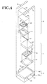
- Fig. 4 is an exploded perspective view of the diaper 1.
- the inner sheet 10a and the outer sheet 10b are shown as before laminated to form the liner sheet 10.
- the inner sheet 10a is provided with a pair of the front wings 23 and a pair of the rear wings 24 attached thereto.
- the first outer sheet 31, the first core 33, the first body fluid spreadable sheet 34 and the first inner sheet 32 forming together the first panel 11 are shown in this order from the bottom.
- the spacer 51 is shown above the first inner sheet 32.
- the second outer sheet 41, the second core 43, the second body fluid spreadable sheet 44 and the second inner sheet 42 forming together the second panel 12 are shown in this order from the bottom.
- the second panel 12 can be effectively spaced from the first panel 11 merely by adopting one of two means as have been described above, i.e., bonding the leak-barrier cuffs to the second panel 12 along the regions 61 and provision of the spacer 51. Which means should be adopted depends on various factors such as the contractile forces of the elastic members 21 and the elastic member (s) 52 and the flexural stiffness of the first and second panels 11, 12 in the transverse direction B.
- the inner surfaces of the first core 33 and the second core 43 may be covered with the body fluid spreadable first sheet 34 and the body fluid spreadable second sheet 44, respectively, to facilitate body fluid to spread on the respective inner surfaces of these cores 33, 43.
- first and second cores 33, 43 contain super-absorbent polymer particles
- the sheets 34, 44 are able to prevent falling off of such particles from the first and second cores 33, 43.
- the body fluid spreadable first and second sheets 34, 44 functioning as has been described above may cover, in addition to the inner surfaces of the first and second cores 33, 43, the outer surfaces thereof. If the first inner sheet 32 and the second inner sheet 42 have the same function as that of the first and second body fluid spreadable sheets 34, 44, these first and second body fluid spreadable sheets 34, 44 may be left out from the diaper 1. If it is unnecessary to form the first panel 11 of the diaper 1 with the depression 36, it is possible to use the first core 33 having not the region 66, instead of the first core 33 as seen in Fig. 4. The waist elastic member 20 as well as the leg elastic members 27 may be also left out if unnecessary.
- Fig. 5 is a diagram exemplarily illustrating the process for continuously making the diaper of Fig. 1.
- first continuous nonwoven fabric web 101 is fed in a first machine direction MD 1 .
- the first continuous nonwoven fabric web 101 has an inner surface 101a and an outer surface 101b.
- the inner surface 101a is coated with hot melt adhesive (not shown), then the first cores 33 of Fig. 2 are arranged intermittently in the first machine direction MD 1 and these first cores 33 are coated on the inner surfaces thereof with hot melt adhesive (not shown).
- a first continuous body fluid-pervious and -spreadable sheet 103 is fed in the first machine direction MD 1 so that the respective first cores 33 may be sandwiched between the first continuous body fluid spreadable sheet 103 and the first continuous nonwoven fabric web 101, then transversely opposite side edges of the first continuous nonwoven fabric web 101 are folded about and sealed with transversely opposite side edges of the first continuous body fluid spreadable sheet 103 by means of adhesive or any suitable welding technique.
- a first continuous liquid-pervious sheet 106 which is body fluid-pervious is fed in the first machine direction MD 1 so that the first cores 33 and the first continuous body fluid spreadable sheet 103 may be sandwiched between the first continuous liquid-pervious sheet 106 and the first continuous nonwoven fabric web 101, then the first continuous liquid-pervious sheet 106 is bonded to the first continuous body fluid spreadable sheet 103 and the first continuous nonwoven fabric web 101 by means of adhesive or any suitable welding technique to obtain first continuous assembly 107.
- a second continuous body fluid spreadable sheet 202 such as tissue paper which is body fluid-pervious and -spreadable is fed in the second machine direction MD 2 so that the respective second cores 43 may be sandwiched between the second continuous body fluid spreadable sheet 202 and the second continuous nonwoven fabric web 201 while transversely opposite side edges of the second continuous nonwoven fabric web 201 are folded about and sealed with transversely opposite side edges of the second continuous body fluid spreadable sheet 202 by means of adhesive or any suitable welding technique.
- elastically stretch- and contractable continuous spacer 204 is fed under tension onto the outer surface 201b of the second continuous nonwoven fabric web 201 in the second machine direction MD 2 so as to straddle the rear sections 47 of the respective second cores 43 (See Fig. 2) and then bonded to the second continuous nonwoven fabric web 201 in the vicinity of the side edges 43a of the respective second cores 43 (See Fig. 3) by means of adhesive or any suitable welding technique.
- a second continuous liquid-pervious sheet 203 which is body fluid-pervious is fed in the second machine direction MD 2 so that the second cores 43 and the second continuous body fluid spreadable sheet 202 may be sandwiched between the second liquid-pervious sheet 203 and the second continuous nonwoven fabric web 201 while the second continuous liquid-pervious sheet 203 is bonded to the second continuous body fluid spreadable sheet 202 and the second continuous nonwoven fabric web 201 by means of adhesive or any suitable welding technique to obtain a second continuous assembly 205.
- a third machine direction MD 3 is the direction in which the first continuous assembly 107 and the second continuous assembly 205 are fed together and this direction MD 3 is an extension of the first machine direction MD 1 and the second machine direction MD 2 .
- a tenth step 510 proceeding in this third machine direction MD 3 the first continuous assembly 107 and the second continuous assembly 205 are let flow into each other in a third cross direction CD 3 crossing the third machine direction MD 3 so that the first cores 33 and the second cores 43 may fall in the corresponding positions in the third machine direction MD 3 and the rear sections 47 of the second cores 43 may overlap the front sections 38 (See Fig. 2) of the first cores 33 from above.
- the first continuous liquid-pervious sheet 106 and the second continuous nonwoven fabric web 201 are bonded to each other by means of adhesive or any suitable welding technique in a shaded region defined between each pair of the adjacent second cores 43, 43 to obtain a third continuous assembly 301.
- the third continuous assembly 30 is successively cut along cutting lines 302 extending in the third cross direction CD 3 to obtain first composites 305 each comprising one of the first cores 33 and one of the second cores 43 and having first and second side edges 303, 304 defined by a pair of the adjacent cutting lines 302, 302.
- the first composite 305 is turned by an angle of 90°.
- the first composite 305 having been turned in this manner has front and rear ends 305a, 305b.
- a continuous liquid-impervious sheet 401 having an inner surface 401a and an outer surface 401b is fed in this fourth machine direction MD 4 .
- the inner surface 401a is defined by liquid-impervious plastic film and the outer surface 401b is defined by nonwoven fabric wherein these film and nonwoven fabric are laminated together by means of adhesive or any suitable welding technique.
- a fifteenth step 515 the first composites 305 having been turned by 90° in the thirteenth step 513 are placed upon the continuous liquid-impervious sheet 401 intermittently in the fourth machine direction MD 4 with the first and second continuous nonwoven fabric webs 101, 201 facing the inner surface 401a of the continuous liquid-impervious sheet 401 and then peripheral edges of the first composites 305 are bonded to the inner surface 401a by means of adhesive or any suitable welding technique to obtain a fourth continuous assembly 402.
- first and second continuous cuffs 403, 404 which are elastically stretch- and contractable belt-like members for leak-barrier are respectively fed under tension in the fourth machine direction MD 4 and outer edges 403b, 404b of these first and second continuous cuffs 403, 404 are bonded to the fourth continuous assembly 402 by means of adhesive or any suitable welding technique in the vicinity of the first and second edges 303, 304, respectively, of the first composites 305.
- the first and second continuous cuffs 403, 404 are placed upon the first continuous liquid-pervious sheet 106 and the second continuous liquid-pervious sheet 203 with inner edges 403a, 404a of the first and second continuous cuffs 403, 404 being opposed to each other and then the first and second continuous cuffs 403, 404 are bonded to the fourth continuous assembly 402 in the vicinity of the front and rear edges 305a, 305b of the first composites 305.
- the inner edges 403a, 404a of the first and second continuous cuffs 403, 404 are partially bonded, in an intermediate region of the fourth continuous assembly 402 in a fourth cross direction CD 4 crossing the fourth machine direction MD 4 , to the second continuous liquid-pervious sheet 203 by means of adhesives 403c, 404c.
- the first and second continuous cuffs 403, 404 fed in the sixteenth step 516 respectively comprise nonwoven fabric webs 403d, 404d which are continuous in the fourth machine direction MD 4 and rubber threads 403e, 404e attached in stretched state to these nonwoven fabric webs 403d, 404d.
- the diaper obtained through the manufacturing process as has been described above is similar to the diaper 1 of Fig. 1 except that this diaper is provided with neither the waist elastic member nor the leg elastic members. These elastic members will be described in details with reference to Figs. 6 and 7.
- the step of feeding the continuous spacer 204 in the eighth step 508 may be left out if the spacer 51 is unnecessary for the diaper 1 of Figs. 2 and 3.
- the step of partially bonding the inner edges 403a, 404a of the first and second continuous cuffs 403, 404 to the second continuous liquid-pervious sheet 203 by means of adhesive 403c, 404c may be left out.
- the first body fluid spreadable sheet 34 and the second body fluid spreadable sheet 44 are unnecessary for the diaper 1, feeding of the first continuous body fluid spreadable sheet 103 in the third step 503 and feeding of the second continuous body fluid spreadable sheet 202 in the seventh step 507 may be left out.
- the first panel 11 is obtained from the first continuous nonwoven fabric web 101, the first core 33, the first continuous body fluid spreadable sheet 103 and the first continuous liquid-pervious sheet 106 illustrated in Fig. 5 while the second panel 12 is obtained from the second continuous nonwoven fabric web 201, the second core 43, the second continuous body fluid spreadable sheet 202, the continuous spacer 204 and the second continuous liquid-pervious sheet 203.
- Fig. 6 illustrates the fourteenth step 514 and the fifteenth step 515 which are different from those in Fig. 5.
- continuous elastic members 411, 412 destined to form the leg elastic members 27 in Fig. 1 are attached in stretched state to the outer sheet 401b constituting the continuous liquid-impervious sheet 401 along the side edges 413, 414 thereof by means of adhesive (not shown).
- the inner sheet 401a and the outer sheet 401b are bonded together by means of adhesive (not shown) to obtain the continuous liquid-impervious sheet 401.
- the first composites 305 are bonded to the continuous liquid-impervious sheet 401 to obtain the fourth continuous assembly 402.
- This fourth continuous assembly 402 may be utilized to attach the leg elastic members to the diaper 1 obtained through the manufacturing process illustrated by Fig. 5.
- Fig. 7 also illustrates the fourteenth step 514 and the fifteenth step 515 which are different from those in Fig. 5.
- the elastic members 20 (See Fig. 1) each extending in the fourth cross direction CD 4 are bonded in stretched state to the outer sheet 401b constituting the continuous liquid-impervious sheet 401 by means of adhesive (not shown).
- Each of the elastic members 20 corresponds to the waist elastic member 20 of the diaper 1 shown by Fig. 1 and, in Fig. 7, each of the elastic members 20 consists of two elastic elements and such elastic members 20 are attached to the outer sheet 401b intermittently in the fourth machine direction MD 4 . Then the inner sheet 401a is laminated with the outer sheet 401b.
- the first composites 305 are placed upon and bonded to the inner sheet 401a between each pair of the adjacent elastic members 20, 20 to obtain the fourth continuous assembly 402.
- Such fourth continuous assembly 402 including the elastic members 20 may be utilized to attach the waist elastic member 20 to the diaper 1 obtained through the manufacturing processes illustrated by Figs. 5 and 6.
- Fig. 8 illustrates a part of the manufacturing process according to one preferred embodiment of the invention comprising the steps similar to those in Fig. 5.
- the front section 38 and the rear section 39 of the first core 33 are oriented in the first machine direction MD 1 when the first core 33 is placed on the first continuous nonwoven fabric web 101 running in the first machine direction MD 1 .
- the front section 46 and the rear section 47 of the second core 43 are oriented in the second machine direction MD 2 when the second core 43 is placed on the second continuous nonwoven fabric web 201 running in the second machine direction MD 2 .
- a plurality of mechanical devices substantially horizontalized in the first machine direction MD 1 and a plurality of mechanical devices substantially horizontalized in the second machine direction MD 2 may be installed above and below so that these two machine directions MD 1 , MD 2 may flow into each other from above and below to reduce a transverse space of the plant for making the diaper.
- This second panel precursors 213 are turned by an angle of 90° and then these second panel precursors 213 are placed on the second continuous assembly 107 running in the first machine direction MD 1 .
- such manufacturing process facilitates the continuous spacer 204 to be continuously fed and facilitates also the rubber thread extending in the circumferential direction of the waist such as the waist elastic member 20 to be continuously fed to the second panel precursor 213.
- the leak-barrier cuffs 13 move upward from the panel-like component 2 so as to rise thereon under contractile force of the elastic members 21 as the diaper 1 is put on the wearer's body and consequently further bows. Thereupon, the portion of the rear section 47 of the second panel 12 forming the fold 12d and the pocket 56 is lifted by the cuffs 13. A top 12e of the fold 12d lifted in this manner is adapted to come in contact with the wearer's skin between the genital organ and the anus so that the fold 12d may function to block loose passage flowing forward as well as urine flowing rearward.
- Such fold 12d in the diaper 1 can be formed by folding back the desired regions of the first continuous assembly 205 in the course defined between the ninth step 509 and the tenth step 510 in the manufacturing process illustrated by Fig. 5.
- the method for making the diaper according to this invention is capable of continuous production of the disposable diaper having the feces retaining pocket formed by overlapping the first and second panels each other in the vicinity of the crotch region improved so that this pocket can be widely opened by spacing these first and second panels from each other.
Abstract
Description
- This invention relates to a method for continuously making disposable diaper, more particularly disposable diaper formed with a feces retaining pocket.
- The disposable diaper formed with the feces retaining pocket has already been well known. The disposable diaper disclosed in
Japanese Unexamined Patent Application Publication No. 2002-315778
PATENT DOCUMENT 1:Japanese Unexamined Patent Application Publication No. 2002-315778 - The feces retaining pocket of the diaper disclosed in Reference has a size when it is fully opened depending on a vertical dimension from f bottom of the depression to the smaller panel and a transverse dimension of the depression. To ensure that the pocket is adequately opened, the side of the pocket may be dimensioned as largely as desired. However, if a depth of the depression is increased in order to meet this requirement, a thickness of the larger panel will be correspondingly increased and the crotch region of the diaper will become correspondingly bulky. From another viewpoint, if the core of the smaller panel is swollen and/or a stiffness of this core is reduced as the smaller panel absorbs body fluid, the smaller panel may hang into the depression so as to reduce the opening size of the pocket and make it difficult for the pocket to receive feces reliably.
- In view of the problem as has been described above, it is a principal object of this invention to provide the method for continuously making the disposable diaper including the feces retaining pocket formed by overlapping a pair of the panels each other, for example, as disclosed in Reference improved so that the size of the pocket when it is opened may be effectively enlarged by spacing a pair of panels from each other in a unique manner.
- According to these first, second and third aspects, this invention provides a method for continuously making a disposable diaper, the disposable diaper defining a front waist region, a rear waist region and a crotch region extending between these two waist regions, the disposable diaper having a longitudinal direction, a transverse direction and a thickness direction and comprising a liquid-impervious sheet having a first inner surface and a first outer surface opposite to the first inner surface, a first body absorbent panel lying on the side of the first inner surface and having a second outer surface facing the first inner surface and a second inner surface opposite to the second outer surface, the first body fluid absorbent panel extending in the longitudinal direction over at least the rear waist region and the crotch region, and a second body fluid absorbent panel having a third outer surface facing at least a part of the second inner surface and a third inner surface opposite to the third outer surface, the second body fluid absorbent panel extending in the longitudinal direction over the front waist region and the crotch region but not to the rear waist region so that the second body fluid absorbent panel overlaps the first body fluid absorbent panel in the crotch region, wherein the second body fluid absorbent panel is bonded along its transversely opposite side edges to one of the liquid-impervious sheet and the first body fluid absorbent panel so that a region of the second body fluid absorbent panel defined between the transversely opposite side edges may be spaced from said first body fluid absorbent panel in the thickness direction, the method for continuously making the disposable diaper comprising that means to space the second body fluid absorbent panel from the first body fluid absorbent panel can be formed through a manufacturing process comprising steps as will be described below.
- A method for continuously making a disposable diaper according to the first aspect of the invention comprises the steps of:
- (1) continuously feeding first nonwoven fabric web destined to form the first body fluid absorbent panel in a first machine direction;
- (2) placing first body fluid absorbent cores on an inner surface of the first nonwoven fabric web having the inner and outer surfaces intermittently in the first machine direction;
- (3) continuously feeding a first liquid-pervious sheet in the first machine direction so that the first cores may be sandwiched between the first liquid-pervious sheet and the first nonwoven fabric web to form a first continuous assembly comprising a plurality of the first body fluid panels connected one with another in the first machine direction;
- (4) continuously feeding second nonwoven fabric web destined to form the second body fluid absorbent panel in a second machine direction;
- (5) placing second body fluid absorbent cores on inner surface of the second nonwoven fabric web having the inner surface and outer surface intermittently in the second machine direction;
- (6) continuously feeding a second liquid-pervious sheet in the second machine direction so that the second cores may be sandwiched between the second liquid-pervious sheet and the second nonwoven fabric web to form a second continuous assembly comprising a plurality of the second body fluid panels connected one with another in the second machine direction;
- (7) feeding the first and second continuous assemblies so as to flow into each other in a third machine direction which is an extension of the first and second machine directions so that the first liquid-pervious sheet and the second nonwoven fabric web may face each other, the first cores and second cores may fall in positions mutually aligned in the third machine direction and the first and second continuous assemblies may overlap each other in a cross direction crossing the third machine direction;
- (8) bonding respective overlapping sections of the first and second continuous assemblies to each other in the vicinity of transversely opposite side edges of the second cores as viewed in the third machine direction to obtain a third continuous assembly consisting of the first and second continuous assemblies;
- (9) successively cutting the third continuous assembly along cutting lines extending in the cross direction to obtain a plurality of first composites including each of the first cores as well as each of the second cores and first and second edges extending in parallel to each other defined by each pair of the cutting lines;
- (10) continuously feeding a first liquid-impervious sheet having inner and outer surfaces in a fourth machine direction and placing the first composites one by one on the first liquid-impervious sheet with the first nonwoven fabric web sheet as well as the second nonwoven fabric web facing the inner surface of the first liquid-impervious sheet and then bonding respective peripheral edges of the first composites to the first liquid-impervious sheet to obtain a fourth continuous assembly;
- (11) bonding a pair of continuous leak-barrier cuffs each having first and second side edges extending in parallel to each other, the second side edges made of belt-like material being elastically stretch- and contractable in a longitudinal direction thereof, along the first side edges to the fourth continuous assembly with the second side edges being stretched, in the vicinity of the first and second edges of the first composites attached to the fourth continuous assembly;
- (12) placing the continuous cuffs bonded to the fourth continuous assembly in the vicinity of the first edge and the continuous cuffs bonded to the fourth continuous assembly in the vicinity of the second edge upon the first liquid-pervious sheet and the second liquid-pervious sheet with the second side edges facing to each other and then bonding the continuous cuffs to the first-composites in the vicinity of respective ends crossing the first and second edges;
- (13) partially bonding the second side edges of respective the continuous cuffs to the second liquid-pervious sheet in an intermediate region of the fourth continuous assembly as viewed in a cross direction crossing the fourth machine direction to form first one of the spacing means; and
- (14) following said step (13), successively cutting the fourth continuous assembly along a line defined between each pair of adjacent the first composites to obtain individual the diapers or precursors of the individual diapers.
- Of the diaper obtained by the method according to the first aspect of the invention, the first body fluid absorbent panel is formed by the first nonwoven fabric web and the first liquid-pervious sheet sandwiching the first core therebetween and the second body fluid absorbent panel is formed by the second nonwoven fabric web and the second liquid-pervious sheet sandwiching the second core therebetween. Each pair of the leak-barrier cuffs is formed by a pair of continuous cuffs. In response to contraction of the second side edges of the cuffs made of leak-barrier belt-like material as such diaper is put on the wearer's body, the second body fluid absorbent panel having the second liquid-pervious sheet bonded to the second side edges of the cuffs are lifted up to be spaced from the first body fluid absorbent panel. Consequentially, the first body fluid absorbent panel cooperates with the second body fluid absorbent panel to form the feces retaining pocket defining a large opening. The method according to the first aspect of the invention allows the leak-barrier cuffs to function as the first means to space the first and second body fluid absorbent panels from each other by bonding the continuous cuffs are to the second liquid-pervious sheet as has been described above.
- According to one preferred embodiment of the invention on the first aspect as defined by
Claim 2, the first liquid-impervious sheet comprises liquid-impervious plastic film and a nonwoven fabric layer laminated on at least one of inner and outer surfaces of the film. The diaper made in this manner advantageously provides the wearer with comfortable cloth-like touch. - According to another preferred embodiment of the invention on the first aspect as defined by
Claim 3, the belt-like material comprises a nonwoven fabric layer and rubber thread attached in stretched state to the nonwoven fabric layer. The method of this manner facilitates the elastically stretch- and contractable leak-barrier cuffs to be made. - According to still another preferred embodiment of the invention on the first aspect as defined by
Claim 4, the first machine direction and the second machine direction coincide with a transverse direction of the liquid-impervious sheet while the fourth machine direction coincides with the longitudinal direction of the liquid-impervious sheet and the first composite is placed upon the first liquid-impervious sheet after the first composite has been turned by an angle of 90°. The method of this manner facilitates the elastic members continuously extending in the transverse direction to be attached to the diaper because the transverse direction of the diaper coincides with the first and second machine directions. - According to further another preferred embodiment of the invention on the first aspect as defined by
Claim 5, the step (6) is followed by the step (7) in which the second continuous assembly placed upon the first continuous assembly is partially folded back along folding guide lines extending in parallel to the second machine direction so that the second liquid-pervious sheet may overlap itself and the second nonwoven fabric web constituting the second continuous assembly may face the continuous cuffs and, in the step (13), the second side edges of said continuous cuffs are partially bonded to the second nonwoven fabric web instead of the second liquid-pervious sheet. The method of this manner allows the continuous cuffs to be bonded to the second nonwoven fabric web cooperating with the second liquid-pervious sheet to sandwich the second cores. - According to an additional preferred embodiment of the invention on the first aspect as defined by
Claim 6, the first machine direction and the second machine direction coincide with the longitudinal direction of the liquid-impervious sheet. With the method of this manner, it is possible to arrange the courses along which the first and second nonwoven fabric webs are fed above and below and thereby to reduce the transverse space in the production line because the longitudinal direction of the diaper coincides with both the first machine direction and the second machine direction. - According to further additional preferred embodiment of the invention on the first aspect as defined by
Claim 7, the first machine direction coincides with the longitudinal direction of the liquid-impervious sheet while the second machine direction coincides with the transverse direction of the liquid-impervious sheet and the method further include a step of turning the first body fluid absorbent panel obtained by cutting the first continuous assembly or the second body fluid absorbent panel obtained by cutting the second continuous assembly by an angle of 90°. The method of this manner facilitates the elastic members extending in the transverse direction of the diaper to be continuously fed and attached to the second nonwoven fabric web. - According to an alternative preferred embodiment of the invention on the first aspect as defined by Claim 8, the method further includes a step of attaching, in stretched state, continuous spacer made of belt-like elastic material as second one of the spacing means functioning to reduce a width of the diaper in the crotch region thereby to space the first and second body fluid absorbent panels from each other to the first or second continuous assembly. The method of this manner allows the continuous cuffs as well as the continuous spacer as the means serving to reduce the width of the diaper.
- A method for continuously making a disposable diaper according to the second aspect of the invention as defined by Claim 9 comprises the steps of:
- (1) continuously feeding first nonwoven fabric web destined to form the first body fluid absorbent panel in a first machine direction;
- (2) placing first body fluid absorbent cores on an inner surface of the first nonwoven fabric web having the inner and outer surfaces intermittently in the first machine direction;
- (3) continuously feeding a first liquid-pervious sheet in the first machine direction so that the first cores may be sandwiched between the first liquid-pervious sheet and the first nonwoven fabric web to form a first continuous assembly comprising a plurality of the first body fluid panels connected one with another in the first machine direction;
- (4) continuously feeding second nonwoven fabric web destined to form the second body fluid absorbent panel in a second machine direction;
- (5) placing second body fluid absorbent cores on inner surface of the second nonwoven fabric web having the inner surface and outer surface intermittently in the second machine direction;
- (6) continuously feeding a second liquid-pervious sheet in the second machine direction so that the second cores may be sandwiched between the second liquid-pervious sheet and the second nonwoven fabric web to form a second continuous assembly comprising a plurality of the second body fluid panels connected one with another in the second machine direction;
- (7) feeding continuous spacer made of belt-like elastic material, in stretched state, in the first machine direction or in the second machine direction so that the continuous spacer may straddle the first cores in the first continuous assembly or the second cores in the second continuous assembly and bonding the continuous spacer to the first liquid-pervious sheet in the first continuous assembly or the second nonwoven fabric web in the second continuous assembly
- (8) feeing the first and second continuous assemblies so as to flow into each other in a third machine direction which is an extension of the first and second machine directions so that the first liquid-pervious sheet and the second nonwoven fabric web may face each other, the first cores and second cores may fall in the corresponding positions in the third machine direction and the first and second continuous assemblies may overlap each other in a cross direction crossing the third machine direction;
- (9) bonding respective overlapping sections of the first and second continuous assemblies to each other in the vicinity of transversely opposite side edges of the second cores as viewed in the third machine direction to obtain a third continuous assembly consisting of the first and second continuous assemblies;
- (10) successively cutting the third continuous assembly along cutting lines extending in the cross direction to obtain a plurality of first composites including each of the first cores as well as each of the second cores and first and second edges extending in parallel to each other defined by each pair of the cutting lines;
- (11) continuously feeding a first liquid-impervious sheet having inner and outer surfaces in a fourth machine direction and placing the first composites one by one on the first liquid-impervious sheet with the first nonwoven fabric web sheet as well as the second nonwoven fabric web facing the inner surface of the first liquid-impervious sheet and then bonding respective peripheral edges of the first composites to the first liquid-impervious sheet to obtain a fourth continuous assembly; and
- (12) following said step (11), successively cutting the fourth continuous assembly along a line defined between each pair of the adjacent first composites to obtain individual the diapers or precursors of the individual diapers.
- According to the second aspect of this invention, the second spacing means to space the first and second body fluid absorbent panels from each other can be obtained by the step of bonding the continuous spacer made of belt-like elastic material, in stretched state, to the first continuous assembly or to the second continuous assembly so as to straddle the first cores or the second cores.
- According to one preferred embodiment of the invention on the second aspect as defined by
Claim 10, the first liquid-impervious sheet comprises liquid-impervious plastic film and a nonwoven fabric layer laminated on at least one of inner and outer surfaces of the film. The diaper made in this manner advantageously provides the diaper wearer with comfortable cloth-like touch. - According to another preferred embodiment of the invention on the second aspect as defined by
Claim 11, the first machine direction and the second machine direction coincide with a transverse direction of the liquid-impervious sheet while the fourth machine direction coincides with the longitudinal direction of the liquid-impervious sheet and the first composite is placed upon the first liquid-impervious sheet after the first composite has been turned by an angle of 90°. The method of this manner facilitates the elastic members continuously extending in the transverse direction to be attached to the diaper because the transverse direction of the diaper coincides with the first and second machine directions. - According to still another preferred embodiment of the invention on the second aspect as defined by
Claim 12, the first machine direction and the second machine direction coincide with the longitudinal direction of the liquid-impervious sheet. With the method of this manner, it is possible to arrange the courses along which the first and second nonwoven fabric webs are fed above and below and thereby to reduce the transverse space in the production line because the longitudinal direction of the diaper coincides with both the first machine direction and the second machine direction. - According to further another preferred embodiment of the invention on the second aspect as defined by
Claim 13, the first machine direction coincides with the longitudinal direction of the liquid-impervious sheet while the second machine direction coincides with the transverse direction of the liquid-impervious sheet and the method further include a step of turning the first body fluid absorbent panel obtained by cutting the first continuous assembly or the second body fluid absorbent panel obtained by cutting the second continuous assembly by an angle of 90°. The method of this manner facilitates the elastic members extending in the transverse direction of the diaper to be continuously fed and attached to the second nonwoven fabric web. - According to an additional preferred embodiment of the invention on the second aspect as defined by Claim 14, the method further includes a step of bonding a pair of continuous leak-barrier cuffs each having first and second side edges extending in parallel to each other, the second side edges made of belt-like material being elastically stretch- and contractible in a longitudinal direction thereof, along the first side edges to the fourth continuous assembly with the second side edges being stretched, in the vicinity of the first and second edges of the first composites attached to the fourth continuous assembly. With the method of this manner, the continuous cuffs can be linearly fed in the fourth machine direction and attached to the fourth continuous assembly running in the fourth machine direction.
- According to further additional preferred embodiment of the invention on the second aspect as defined by Claim 15, the method further includes a step of partially bonding the continuous cuffs to any one of the second liquid-pervious sheet and the second nonwoven fabric web sandwiching the second cores. The method of this manner allows the leak-barrier cuffs to function as the additional means to space the first and second body fluid absorbent panels of the diaper from each other.
- A method for continuously making a disposable diaper according to the invention on the third aspect as defined by
Claim 16 comprises the steps of: -
- (1) continuously feeding said liquid-impervious sheet having said first inner surface and said first outer surface in a first machine direction;
- (2) attaching said first body fluid absorbent panels to said first inner surface of said continuously fed liquid-impervious sheet so that each of said first body fluid absorbent panels may extend at least over a section allocated for said rear waist and crotch regions;
- (3) placing said second body fluid absorbent panels on said continuously fed liquid-impervious sheet so that each of said second body fluid absorbent panels may extend over a section of said continuously fed liquid-impervious sheet allocated for said front waist and crotch regions and said second outer surface of said second body fluid absorbent panel may face said first inner surface of said first body fluid absorbent panel in said crotch region and then bonding, in said crotch region, said transversely opposite edges of said second body fluid absorbent panel to transversely opposite side edges of said first body fluid absorbent panel or to transversely opposite side edges of said continuously fed liquid-impervious sheet extending outside said transversely opposite side edges of said first body fluid absorbent panel;
- (4) feeding, in stretched state, a pair of leak-barrier cuff members formed by belt-like material extending from said section allocated for said crotch region to said sections allocated for said front and rear waist regions, said belt-like material being elastically stretch- and contractable in a direction in which said belt-like material extends and having inner and outer side edges, to said continuously fed liquid-impervious sheet having said first and second body fluid absorbent panels attached thereto, then, in said crotch regions, attaching said outer side edges of said respective cuff members to said continuously fed liquid-impervious sheet outside respective said side edges of said first and second body fluid absorbent panels and covering edges of said first and second body fluid absorbent panels with said inner side edges of respective said cuff members; and
- (5) forming said spacing means by at least one of substeps a) and b) as follow:
- a. bonding, in each section of said continuously fed liquid-impervious sheet allocated for said crotch region, portions of said inner side edges of said leak-barrier cuff members in stretched state to the portions of said second body fluid absorbent panel covered with said portions of said inner side edges; and
- b. attaching, in each section of said continuously fed liquid-impervious sheet allocated for said crotch region, a belt-like elastic spacer transversely extending in stretched state between said first and second body fluid absorbent panels to said side edges of at least one of said first and second body fluid absorbent panels.
- In such manufacturing process according to the third aspect of the invention, the first and/or second means to space the second body fluid absorbent panel from the first body fluid absorbent panel can be obtained by at least one of substeps of bonding, in each section of the continuously fed liquid-impervious sheet allocated for the crotch region, portions of the inner side edges of the leak-barrier cuff members in stretched state to the portions of the second body fluid absorbent panel covered with the portions of the inner side edges; and attaching, in each section of the continuously fed liquid-impervious sheet allocated for the crotch region, a belt-like elastic spacer transversely extending in stretched state between the first and second body fluid absorbent panels to the side edges of at least one of the first and second body fluid absorbent panels.
-
- [FIG. 1] Fig. 1 is a perspective view showing a diaper obtained by the process according to the invention.
- [FIG. 2] Fig. 2 is a sectional view taken along the line II-II in Fig. 1.
- [FIG. 3] Fig. 3 is a sectional view taken along the line III-III in Fig. 1.
- [FIG. 4] Fig. 4 is an exploded perspective view showing the diaper.
- [FIG. 5] Fig. 5 is a diagram illustrating the process for making the diaper.
- [FIG. 6] Fig. 6 is a diagram partially illustrating the process according to one preferred embodiment of the invention.
- [FIG. 7] Fig. 7 is a diagram partially illustrating the process according to another preferred embodiment of the invention.
- [FIG. 8] Fig. 8 is a diagram partially illustrating the process according to still another preferred embodiment of the invention.
- [FIG. 9] Fig. 9 is a diagram partially illustrating the process according to further another preferred embodiment of the invention.
- [FIG. 19] Fig. 10 is a perspective view showing a diaper constructed in a manner different from the diaper of Fig. 1.
- [FIG. 11] Fig. 11 is a sectional view taken along the line XI-XI in Fig. 10.
-
- 1
- disposable diaper
- 3
- front waist region
- 4
- rear waist region
- 5
- crotch region
- 10
- liquid-impervious sheet (liner sheet)
- 10a
- first inner surface
- 10b
- first outer surface
- 11
- first body fluid absorbent section (first panel)
- 11a
- transversely opposite side edges
- 12
- second body fluid absorbent section (second panel)
- 12a
- transversely opposite side edges
- 12d
- region
- 13
- leak-barrier cuffs
- 31
- second outer surface
- 32
- second inner surface
- 33
- first core
- 41
- third outer surface
- 42
- third inner surface
- 43
- second core
- 51
- spacer
- 101
- first nonwoven fabric
- 101a
- inner surface
- 101b
- outer surface
- 106
- first liquid-pervious sheet
- 107
- first continuous assembly
- 201
- second nonwoven fabric
- 201a
- inner surface
- 201b
- outer surface
- 203
- second liquid-pervious sheet
- 204
- continuous spacer web
- 205
- second continuous assembly
- 301
- third continuous assembly
- 302
- cutting line
- 303
- side edge
- 304
- side edge
- 305
- first composite web
- 305a
- first side edge
- 305b
- second side edge
- 401
- first liquid-impervious sheet
- 401a
- inner surface
- 401b
- outer surface
- 402
- fourth continuous assembly
- 403
- first cuff continuous web
- 403a
- first side edge
- 403b
- second side edge
- 403d
- nonwoven fabric
- 403e
- rubber thread
- 404
- second cuff continuous web
- 404a
- first side edge
- 404b
- second side edge
- 404d
- nonwoven fabric
- 404e
- rubber thread
- MD1
- first machine direction
- MD2
- second machine direction
- MD3
- third machine direction
- MD4
- fourth machine direction
- CD3
- cross direction (third cross direction)
- CD4
- cross direction (fourth cross direction)
- A
- longitudinal direction
- B
- transverse direction
- Details of a method according to this invention for continuously making the disposable diaper will be more fully understood from the description given hereunder with reference to the accompanying drawings.
- Fig. 1 is a perspective view showing a
disposable diaper 1 obtained by the inventive method. Thediaper 1 has aninner surface 1a facing the diaper wearer's skin and an outer surface 1b facing away from the wearer's skin. Thediaper 1 has a longitudinal direction, a transverse direction and a thickness direction being orthogonal one to another as indicated by double-headed arrows A, B and C, respectively. The longitudinal direction A can be referred to also as the back-and-forth direction of thediaper 1 and the transverse direction can be referred to also as the width direction of thediaper 1. In thisdiaper 1, a rectangular panel-like component 2 which is relatively long in the longitudinal direction A comprises afront waist region 3, arear waist region 4 and acrotch region 5 extending between these twowaist regions opposite side edges 6 extending in parallel to each other in the longitudinal direction A and a pair of longitudinally opposite ends extending in parallel to each other in the transverse direction B. The panel-like component 2 further comprises a liquid-impervious liner sheet 10 which is, in turn, provided on its inner surface with first and second body fluidabsorbent panels panels barrier cuffs 13, respectively, extending in the longitudinal direction A long therespective side edges 6 of the panel-like component 2. Each of these leak-barrier cuffs 13 has afront end 16, arear end 17, aninner side edge 18 and anouter side edge 19 wherein the front andrear ends outer side edge 19 are bonded to theliner sheet 10. Anelastic member 21 is attached in stretched state to theinner side edge 18. The panel-like component 2 is further provided in therear waist region 4 with a waistelastic member 20 attached in stretched state thereto and provided in the vicinity of therespective side edges 6 with legelastic members 27 attached in stretched state thereto. It should be noted that Fig. 1 shows the panel-like component 2 bowing in the longitudinal direction A with the outer surface 1b of thediaper 1 being convex as theelastic members like component 2, thefront waist region 3 has a pair offront wings 23 extending in the transverse direction B and therear waist region 4 has a pair ofrear wings 24 extending in the transverse direction B. Therear wings 24 are respectively provided on the inner surfaces thereof withfasteners 26 adapted to be detachably anchored on the outer surface of thefront waist region 3 or the outer surfaces of the respectivefront wings 23 at predetermined positions thereon. - Fig. 2 is a sectional view taken along the line II-II in Fig. 1, showing the
diaper 1 which is bowing in the longitudinal direction. In the panel-like component 2, theliner sheet 10 comprises aninner sheet 10a made of liquid-impervious plastic film and anouter sheet 10b laminated with each other and the waistelastic member 20 is interposed between these twosheets first panel 11 extends at least over therear waist region 3 and thecrotch region 5 of the panel-like component 2. In the case of the illustrated embodiment, thefirst panel 11 has afront section 38 placed aside toward thefront waist region 3 and arear section 39 placed aside toward therear waist region 4. Suchfirst panel 11 comprises a firstouter sheet 31 made of nonwoven fabric, preferably liquid-impervious nonwoven fabric, a firstinner sheet 32 made of liquid-pervious nonwoven fabric and a first body fluidabsorbent core 33 interposed between these twosheets first core 33 is a mixture of fluff pulp and body fluid absorbent material such as super-absorbent polymer particles. Preferably, surfaces of such mixture destined to come in contact with the firstouter sheet 31 and the firstinner sheet 32, respectively, or at least the surface destined to come in contact with the firstinner sheet 32 are or is covered with a liquid-pervious first bodyfluid spreadable sheet 34 such as tissue paper. It should be noted that thefirst core 33 in the illustrated embodiment is divided into afront section 33a and arear section 33b between which the firstinner sheet 32 and the first bodyfluid spreadable sheet 34 bow so as to be placed upon the firstouter sheet 31 and to form thefirst panel 11 with adepression 36. In Fig. 1, thisdepression 36 is indicated bychain lines 37 describing a substantially T-shape. - The
second panel 12 of the panel-like component 2 comprises a secondouter sheet 41 made of nonwoven fabric, preferably of liquid-pervious nonwoven fabric, a secondinner sheet 42 made of liquid-pervious nonwoven fabric and a second body fluidabsorbent core 43 interposed between these twosheets second core 43 is a mixture of fluff pulp and body fluid absorbent material such as super-absorbent polymer particles. Preferably, surfaces of such mixture destined to come in contact with the secondouter sheet 41 and the secondinner sheet 42, respectively, or at least the surface destined to come in contact with the secondinner sheet 42 are or is covered with a liquid-pervious second bodyfluid spreadable sheet 44 such as tissue paper. Suchsecond panel 12 extends over thefront waist region 3 and a part of thecrotch region 5 but not to therear waist region 4. Thus thesecond panel 12 has afront section 46 lying in thefront waist region 3 and arear section 47 lying in thecrotch region 5. Thefront section 46 is bonded to theliner sheet 10 by means of adhesive (not shown). Therear section 47 is formed so as to be separably placed upon thefirst panel 11 in thecrotch region 5. In Fig. 2, thisrear section 47 is lifted up and thereby spaced from thefirst panel 11. In apreferred diaper 1, arear end 47a (See Fig. 1 also) of therear section 47 lies between a centerline P bisecting a dimension of thediaper 1 in the longitudinal direction A and a line Q bisecting a dimension from the centerline P to thefront end 7 of the panel-like component 2. Between thefront section 38 of thefirst panel 11 and therear section 47 of thesecond panel 12 spaced from each other, a belt-like spacer 51 is interposed. Thespacer 51 comprises at least a single rubber thread covered, in stretched state, withnonwoven fabric 53.Such spacer 51 is stretched in the transverse direction B of thediaper 1 and attached to thediaper 1 in such stretched state. Fig. 2 shows therubber thread 52 let free to contract. - In the
crotch region 5 ofsuch diaper 1, therear section 47 of thesecond panel 12 define a wall dividing thediaper 1 in front and rear halves and cooperates with thefront section 38 of thefirst panel 38 to define apocket 56 opening toward therear waist region 5. - Fig. 3 is a sectional view taken along the line III-III in Fig. 2. The line III-III lies aside from the centerline P toward the
front waist region 3 and extends through thefirst panel 11 and thesecond panel 12. In the vicinity of therespective side edges 6 of the panel-like component 2, the legelastic members 27 are interposed between theouter sheet 10a and theinner sheet 10b and bonded to at least one of thesesheets respective side edges 11a of thefirst panel 11, the firstouter sheet 31, the firstinner sheet 32 and the first bodyfluid spreadable sheet 34 extend sideways beyond thefirst core 33 and bonded together and bonded also to theinner sheet 10b by means of adhesive or any suitable welding technique. Along the side edges 12a of thesecond panel 12, the secondouter sheet 41, the secondinner sheet 42 and the second bodyfluid spreadable sheet 44 extend sideways beyond thesecond core 43 and bonded together and bonded also to the firstinner sheet 32 of thefirst panel 11 by means of adhesive or any suitable welding technique. Thespacer 51 extends between theside edges first panel 11 as well as between theside edges second panel 12, straddling the first andsecond cores spacer 51 is bonded to the firstinner sheet 32 and/or the secondouter sheet 41 by means of adhesive or any suitable welding technique. The leak-barrier cuffs 13 respectively have the outer side edges 19 lying outside the side edges 11a of thefirst panel 11 as well as the side edges 12a of thesecond panel 12 and bonded to theinner sheet 10a by means of adhesive or any suitable welding technique. The inner side edges 18 of the respective leak-barrier cuffs 13 partially cover thefirst panel 11 and the second panel 12 (See Fig. 1). These inner side edges 18 are bonded to the secondinner sheet 42 of thesecond panel 12 by means of adhesive 60 alongregions 61 indicated by chain lines in the vicinity of the respectiveelastic members 21.Regions 62 defined between theelastic members 21 and theaforementioned regions 61 rise above the secondinner sheet 42 as theelastic members 21 contract. Between a pair of the leak-barrier cuffs 13 constructed in this manner, the inner side edges 18 are spaced from each other by a dimension W so that thefirst panel 11 as well as thesecond panel 12 are partially exposed between these inner side edges 18 (See Fig. 1). In the case of thediaper 1 for baby or infant, the dimension W is preferably in a range of about 20 to about 50mm. - Fig. 4 is an exploded perspective view of the
diaper 1. At the bottom of Fig. 4, theinner sheet 10a and theouter sheet 10b are shown as before laminated to form theliner sheet 10. Theinner sheet 10a is provided with a pair of thefront wings 23 and a pair of therear wings 24 attached thereto. Above theinner sheet 10a, the firstouter sheet 31, thefirst core 33, the first bodyfluid spreadable sheet 34 and the firstinner sheet 32 forming together thefirst panel 11 are shown in this order from the bottom. Above the firstinner sheet 32, thespacer 51 is shown. Above thespacer 51, the secondouter sheet 41, thesecond core 43, the second bodyfluid spreadable sheet 44 and the secondinner sheet 42 forming together thesecond panel 12 are shown in this order from the bottom. Above the secondinner sheet 42, a pair of the leak-barrier cuffs 13 is shown. Referring to Fig. 4, imaginary lines extending in the firstouter sheet 31 and the secondouter sheet 41 indicate guiding lines along which thesesheets diaper 1. Aregion 66 in thefirst core 33 is devoid of core material and thisregion 66 is destined to form thedepression 33 as shown by Fig. 2. A pair of arc-shapedregions 67 in thesecond core 43 are also devoid of core material and facilitate thesecond panel 12 to be deformed around the wearer's legs as thediaper 1 is put on the wearer's body.Such regions 67 appear in Fig. 3 also. - The
diaper 1 constructed in the manner as has been described above bows in the longitudinal direction A as it is put on the wearer's body whereupon the inner side edges 18 of the respective leak-barrier cuffs 13 rise toward the inner side of the diaper 1 (upward as viewed in Fig. 1), i.e., move in a direction from the outer surface toward the inner surface of theliner sheet 10 as theelastic members 21 contract. Thereupon, thesecond panel 12 bonded to the leak-barrier cuffs 13 along theregions 61 is deformed to be lifted off from thefirst panel 11 and thereby to broaden the opening of thepocket 56. In this invention, the leak-barrier cuffs 13 functioning in this manner can serve as first important means to space the first andsecond panels first panel 11 is deformed to become convex toward the outer side of the diaper 1 (i.e., downward as viewed in Fig. 1) while thesecond panel 12 is deformed to become convex toward the inner side of thediaper 1 as thespacer 51 elastically contracts in the transverse direction B of thediaper 1. In this way, thepocket 56 is opened more significantly than thediaper 1 having not thespacer 51. Thespacer 51 functioning in this manner can serve as second important means to space the first andsecond panels rear section 47 of thesecond panel 12 deformed to become convex toward the inner side of thediaper 1 has itsrear end 47a lies between the lines P and Q, in other words, between the genital organ and the anus of the diaper wearer. Suchrear section 47 functions, for example, to block loose passage flowing from therear waist region 4 or thecrotch region 5 toward thefront waist region 3 and to guide this into thepocket 56 and/or to block urine flowing from thefront waist region 3 or thecrotch region 5 toward therear waist region 4. In this way, therear section 47 is able to avoid the apprehension that loose passage and urine might be mixed with each other in thecrotch region 5 and the wearer's skin might be contaminated with this mixture. - It should be understood that, in the
diaper 1, thesecond panel 12 can be effectively spaced from thefirst panel 11 merely by adopting one of two means as have been described above, i.e., bonding the leak-barrier cuffs to thesecond panel 12 along theregions 61 and provision of thespacer 51. Which means should be adopted depends on various factors such as the contractile forces of theelastic members 21 and the elastic member (s) 52 and the flexural stiffness of the first andsecond panels diaper 1, the inner surfaces of thefirst core 33 and thesecond core 43 may be covered with the body fluid spreadablefirst sheet 34 and the body fluid spreadablesecond sheet 44, respectively, to facilitate body fluid to spread on the respective inner surfaces of thesecores cores sheets second cores second sheets second cores inner sheet 32 and the secondinner sheet 42 have the same function as that of the first and second bodyfluid spreadable sheets fluid spreadable sheets diaper 1. If it is unnecessary to form thefirst panel 11 of thediaper 1 with thedepression 36, it is possible to use thefirst core 33 having not theregion 66, instead of thefirst core 33 as seen in Fig. 4. The waistelastic member 20 as well as the legelastic members 27 may be also left out if unnecessary. - Fig. 5 is a diagram exemplarily illustrating the process for continuously making the diaper of Fig. 1. In a
first step 501, first continuousnonwoven fabric web 101 is fed in a first machine direction MD1. The first continuousnonwoven fabric web 101 has aninner surface 101a and an outer surface 101b. In asecond step 502, theinner surface 101a is coated with hot melt adhesive (not shown), then thefirst cores 33 of Fig. 2 are arranged intermittently in the first machine direction MD1 and thesefirst cores 33 are coated on the inner surfaces thereof with hot melt adhesive (not shown). In athird step 503, a first continuous body fluid-pervious and -spreadable sheet 103 is fed in the first machine direction MD1 so that the respectivefirst cores 33 may be sandwiched between the first continuous bodyfluid spreadable sheet 103 and the first continuousnonwoven fabric web 101, then transversely opposite side edges of the first continuousnonwoven fabric web 101 are folded about and sealed with transversely opposite side edges of the first continuous bodyfluid spreadable sheet 103 by means of adhesive or any suitable welding technique. In afourth step 504, a first continuous liquid-pervious sheet 106 which is body fluid-pervious is fed in the first machine direction MD1 so that thefirst cores 33 and the first continuous bodyfluid spreadable sheet 103 may be sandwiched between the first continuous liquid-pervious sheet 106 and the first continuousnonwoven fabric web 101, then the first continuous liquid-pervious sheet 106 is bonded to the first continuous bodyfluid spreadable sheet 103 and the first continuousnonwoven fabric web 101 by means of adhesive or any suitable welding technique to obtain firstcontinuous assembly 107. - In a
fifth step 505, second continuousnonwoven fabric web 201 is fed in a second machine direction MD2. The second continuousnonwoven fabric web 201 has aninner surface 201a and anouter surface 201b. In asixth step 506, theinner surface 201a is coated with hot melt adhesive (not shown), then thesecond cores 43 of Fig. 2 are arranged intermittently in the second machine direction MD2 and thesecond cores 43 are coated on the inner surfaces thereof with hot melt adhesive (not shown). In aseventh step 507, a second continuous bodyfluid spreadable sheet 202 such as tissue paper which is body fluid-pervious and -spreadable is fed in the second machine direction MD2 so that the respectivesecond cores 43 may be sandwiched between the second continuous bodyfluid spreadable sheet 202 and the second continuousnonwoven fabric web 201 while transversely opposite side edges of the second continuousnonwoven fabric web 201 are folded about and sealed with transversely opposite side edges of the second continuous bodyfluid spreadable sheet 202 by means of adhesive or any suitable welding technique. In aeighth step 508, elastically stretch- and contractablecontinuous spacer 204 is fed under tension onto theouter surface 201b of the second continuousnonwoven fabric web 201 in the second machine direction MD2 so as to straddle therear sections 47 of the respective second cores 43 (See Fig. 2) and then bonded to the second continuousnonwoven fabric web 201 in the vicinity of the side edges 43a of the respective second cores 43 (See Fig. 3) by means of adhesive or any suitable welding technique. In aninth step 509, a second continuous liquid-pervious sheet 203 which is body fluid-pervious is fed in the second machine direction MD2 so that thesecond cores 43 and the second continuous bodyfluid spreadable sheet 202 may be sandwiched between the second liquid-pervious sheet 203 and the second continuousnonwoven fabric web 201 while the second continuous liquid-pervious sheet 203 is bonded to the second continuous bodyfluid spreadable sheet 202 and the second continuousnonwoven fabric web 201 by means of adhesive or any suitable welding technique to obtain a secondcontinuous assembly 205. - A third machine direction MD3 is the direction in which the first
continuous assembly 107 and the secondcontinuous assembly 205 are fed together and this direction MD3 is an extension of the first machine direction MD1 and the second machine direction MD2. In atenth step 510 proceeding in this third machine direction MD3, the firstcontinuous assembly 107 and the secondcontinuous assembly 205 are let flow into each other in a third cross direction CD3 crossing the third machine direction MD3 so that thefirst cores 33 and thesecond cores 43 may fall in the corresponding positions in the third machine direction MD3 and therear sections 47 of thesecond cores 43 may overlap the front sections 38 (See Fig. 2) of thefirst cores 33 from above. In aneleventh step 511, the first continuous liquid-pervious sheet 106 and the second continuousnonwoven fabric web 201 are bonded to each other by means of adhesive or any suitable welding technique in a shaded region defined between each pair of the adjacentsecond cores continuous assembly 301. In atwelfth step 512, the third continuous assembly 30 is successively cut along cuttinglines 302 extending in the third cross direction CD3 to obtainfirst composites 305 each comprising one of thefirst cores 33 and one of thesecond cores 43 and having first and second side edges 303, 304 defined by a pair of theadjacent cutting lines thirteenth step 513, thefirst composite 305 is turned by an angle of 90°. Thefirst composite 305 having been turned in this manner has front andrear ends - In a
fourteenth step 514 proceeding in a fourth machine direction MD4, a continuous liquid-impervious sheet 401 having aninner surface 401a and anouter surface 401b is fed in this fourth machine direction MD4. In the case of the continuous liquid-impervious sheet 401 exemplarily shown, theinner surface 401a is defined by liquid-impervious plastic film and theouter surface 401b is defined by nonwoven fabric wherein these film and nonwoven fabric are laminated together by means of adhesive or any suitable welding technique. In afifteenth step 515, thefirst composites 305 having been turned by 90° in thethirteenth step 513 are placed upon the continuous liquid-impervious sheet 401 intermittently in the fourth machine direction MD4 with the first and second continuousnonwoven fabric webs inner surface 401a of the continuous liquid-impervious sheet 401 and then peripheral edges of thefirst composites 305 are bonded to theinner surface 401a by means of adhesive or any suitable welding technique to obtain a fourthcontinuous assembly 402. In asixteenth step 516, first and secondcontinuous cuffs outer edges 403b, 404b of these first and secondcontinuous cuffs continuous assembly 402 by means of adhesive or any suitable welding technique in the vicinity of the first andsecond edges first composites 305. Also in asixteenth step 516, the first and secondcontinuous cuffs pervious sheet 106 and the second continuous liquid-pervious sheet 203 withinner edges 403a, 404a of the first and secondcontinuous cuffs continuous cuffs continuous assembly 402 in the vicinity of the front andrear edges first composites 305. In thesame step 516, theinner edges 403a, 404a of the first and secondcontinuous cuffs continuous assembly 402 in a fourth cross direction CD4 crossing the fourth machine direction MD4, to the second continuous liquid-pervious sheet 203 by means ofadhesives continuous cuffs sixteenth step 516 respectively comprisenonwoven fabric webs rubber threads nonwoven fabric webs continuous assembly 402 are provided at predetermined positions withwing members front wings 23 and therear wings 24, respectively. Thewing members 407, 408 are provided with the fasteners -26 of Fig. 1 attached thereto. In aeighteenth step 518, the fourthcontinuous assembly 402 is successively cut, between a pair of the adjacentfirst composites 305, along cuttinglines 410 extending in the fourth cross direction CD4 to obtain theindividual diapers 1 or precursors of thesediapers 1 between a pair of the adjacentfirst composites 305. As used herein a term "precursor" refers to the diaper destined to be subjected to any subsequent working. - The diaper obtained through the manufacturing process as has been described above is similar to the
diaper 1 of Fig. 1 except that this diaper is provided with neither the waist elastic member nor the leg elastic members. These elastic members will be described in details with reference to Figs. 6 and 7. In thediaper 1 obtained through the manufacturing process illustrated by Fig. 5, the step of feeding thecontinuous spacer 204 in theeighth step 508 may be left out if thespacer 51 is unnecessary for thediaper 1 of Figs. 2 and 3. If it is unnecessary for thediaper 1 to use the leak-barrier cuffs 13 as the means to space thesecond panel 12 from thefirst panel 11, the step of partially bonding theinner edges 403a, 404a of the first and secondcontinuous cuffs pervious sheet 203 by means of adhesive 403c, 404c may be left out. Furthermore, if the first bodyfluid spreadable sheet 34 and the second bodyfluid spreadable sheet 44 are unnecessary for thediaper 1, feeding of the first continuous bodyfluid spreadable sheet 103 in thethird step 503 and feeding of the second continuous bodyfluid spreadable sheet 202 in theseventh step 507 may be left out. As will be apparent from comparison between thediaper 1 of Fig. 1 and the manufacturing process of Fig. 5, thefirst panel 11 is obtained from the first continuousnonwoven fabric web 101, thefirst core 33, the first continuous bodyfluid spreadable sheet 103 and the first continuous liquid-pervious sheet 106 illustrated in Fig. 5 while thesecond panel 12 is obtained from the second continuousnonwoven fabric web 201, thesecond core 43, the second continuous bodyfluid spreadable sheet 202, thecontinuous spacer 204 and the second continuous liquid-pervious sheet 203. - Fig. 6 illustrates the
fourteenth step 514 and thefifteenth step 515 which are different from those in Fig. 5. In thefourteenth step 514 illustrated by Fig. 6, continuouselastic members elastic members 27 in Fig. 1 are attached in stretched state to theouter sheet 401b constituting the continuous liquid-impervious sheet 401 along the side edges 413, 414 thereof by means of adhesive (not shown). Then theinner sheet 401a and theouter sheet 401b are bonded together by means of adhesive (not shown) to obtain the continuous liquid-impervious sheet 401. In thestep 515, thefirst composites 305 are bonded to the continuous liquid-impervious sheet 401 to obtain the fourthcontinuous assembly 402. This fourthcontinuous assembly 402 may be utilized to attach the leg elastic members to thediaper 1 obtained through the manufacturing process illustrated by Fig. 5. - Fig. 7 also illustrates the
fourteenth step 514 and thefifteenth step 515 which are different from those in Fig. 5. In thefourteenth step 514 of Fig. 7, the elastic members 20 (See Fig. 1) each extending in the fourth cross direction CD4 are bonded in stretched state to theouter sheet 401b constituting the continuous liquid-impervious sheet 401 by means of adhesive (not shown). Each of theelastic members 20 corresponds to the waistelastic member 20 of thediaper 1 shown by Fig. 1 and, in Fig. 7, each of theelastic members 20 consists of two elastic elements and suchelastic members 20 are attached to theouter sheet 401b intermittently in the fourth machine direction MD4. Then theinner sheet 401a is laminated with theouter sheet 401b. In thefifteenth step 515, thefirst composites 305 are placed upon and bonded to theinner sheet 401a between each pair of the adjacentelastic members continuous assembly 402. Such fourthcontinuous assembly 402 including theelastic members 20 may be utilized to attach the waistelastic member 20 to thediaper 1 obtained through the manufacturing processes illustrated by Figs. 5 and 6. - Fig. 8 illustrates a part of the manufacturing process according to one preferred embodiment of the invention comprising the steps similar to those in Fig. 5. In the manufacturing process illustrated herein, the
front section 38 and therear section 39 of thefirst core 33 are oriented in the first machine direction MD1 when thefirst core 33 is placed on the first continuousnonwoven fabric web 101 running in the first machine direction MD1. Similarly, thefront section 46 and therear section 47 of thesecond core 43 are oriented in the second machine direction MD2 when thesecond core 43 is placed on the second continuousnonwoven fabric web 201 running in the second machine direction MD2. In this manufacturing process, a plurality of mechanical devices substantially horizontalized in the first machine direction MD1 and a plurality of mechanical devices substantially horizontalized in the second machine direction MD2 may be installed above and below so that these two machine directions MD1, MD2 may flow into each other from above and below to reduce a transverse space of the plant for making the diaper. - Fig. 9 also illustrates a part of the manufacturing process according to one preferred embodiment of the invention comprising the steps similar to those in Fig. 5. In the manufacturing process illustrated herein, the continuous
nonwoven fabric web 101 and thefirst core 33 run in the first machine direction MD1 in the same manner as in Fig. 8. The second continuousnonwoven fabric web 201 and thesecond core 43 run in the second machine direction MD2 in the same manner as in Fig. 5. In the second machine direction MD2, the secondcontinuous assembly 205 is successively cut along the cuttinglines second core 43 and the second bodyfluid spreadable sheet 202 sandwiched between the second continuousnonwoven fabric web 201 and the second continuous liquid-pervious sheet 203 to obtain thesecond panel precursors 213. Thissecond panel precursors 213 are turned by an angle of 90° and then thesesecond panel precursors 213 are placed on the secondcontinuous assembly 107 running in the first machine direction MD1. As in the case of Fig. 5, such manufacturing process facilitates thecontinuous spacer 204 to be continuously fed and facilitates also the rubber thread extending in the circumferential direction of the waist such as the waistelastic member 20 to be continuously fed to thesecond panel precursor 213. - Fig. 10 is a perspective view showing a
diaper 1 similar to thediaper 1 of Fig. 1 and Fig. 11 is a sectional view taken along a line XI-XI in Fig. 10. In thisdiaper 1, therear section 47 of thesecond panel 12 is partially folded back so that the secondinner sheet 42 constituting thesecond panel 12 is folded back face to face in this folded backsegment 12d. In thefold 12d, the secondouter sheet 41 is exposed outside thepocket 56. The leak-barrier cuffs 13 are respectively bonded at theregions 61 thereof to the secondouter sheet 41 in thefold 12d. The leak-barrier cuffs 13 move upward from the panel-like component 2 so as to rise thereon under contractile force of theelastic members 21 as thediaper 1 is put on the wearer's body and consequently further bows. Thereupon, the portion of therear section 47 of thesecond panel 12 forming thefold 12d and thepocket 56 is lifted by thecuffs 13. A top 12e of thefold 12d lifted in this manner is adapted to come in contact with the wearer's skin between the genital organ and the anus so that thefold 12d may function to block loose passage flowing forward as well as urine flowing rearward.Such fold 12d in thediaper 1 can be formed by folding back the desired regions of the firstcontinuous assembly 205 in the course defined between theninth step 509 and thetenth step 510 in the manufacturing process illustrated by Fig. 5. - The method for making the diaper according to this invention is capable of continuous production of the disposable diaper having the feces retaining pocket formed by overlapping the first and second panels each other in the vicinity of the crotch region improved so that this pocket can be widely opened by spacing these first and second panels from each other.
Claims (16)
- A method for continuously making a disposable diaper, said disposable diaper defining a front waist region, a rear waist region and a crotch region extending between these two waist regions, said disposable diaper having a longitudinal direction, a transverse direction and a thickness direction and comprising a liquid-impervious sheet having a first inner surface and a first outer surface opposite to said first inner surface, a first body absorbent panel lying on the side of said first inner surface and having a second outer surface facing said first inner surface and a second inner surface opposite to said second outer surface, said first body fluid absorbent panel extending in said longitudinal direction over at least said rear waist region and said crotch region, and a second body fluid absorbent panel having a third outer surface facing at least a part of said second inner surface and a third inner surface opposite to said third outer surface, said second body fluid absorbent panel extending in said longitudinal direction over said front waist region and said crotch region but not to said rear waist region so that said second body fluid absorbent panel may overlap said first body fluid absorbent panel in said crotch region, wherein said second body fluid absorbent panel is bonded along its transversely opposite side edges to one of said liquid-impervious sheet and said first body fluid absorbent panel so that a region of said second body fluid absorbent panel defined between said transversely opposite side edges may be spaced from said first body fluid absorbent panel in said thickness direction, said method for continuously making the disposable diaper comprising that means to space said second body fluid absorbent panel from said first body fluid absorbent panel can be formed through a manufacturing process comprising the steps of:(1) continuously feeding first nonwoven fabric web destined to form said first body fluid absorbent panel in a first machine direction;(2) placing first body fluid absorbent cores on an inner surface of said first nonwoven fabric web having said inner and outer surfaces intermittently in said first machine direction;(3) continuously feeding a first liquid-pervious sheet in said first machine direction so that said first cores may be sandwiched between said first liquid-pervious sheet and said first nonwoven fabric web to form a first continuous assembly comprising a plurality of said first body fluid panels connected one with another in said first machine direction;(4) continuously feeding second nonwoven fabric web destined to form said second body fluid absorbent panel in a second machine direction;(5) placing second body fluid absorbent cores on inner surface of said second nonwoven fabric web having said inner surface and outer surface intermittently in said second machine direction;(6) continuously feeding a second liquid-pervious sheet in said second machine direction so that said second cores may be sandwiched between said second liquid-pervious sheet and said second nonwoven fabric web to form a second continuous assembly comprising a plurality of said second body fluid panels connected one with another in said second machine direction;(7) feeding said first and second continuous assemblies so as to flow into each other in a third machine direction which is an extension of the first and second machine directions so that said first liquid-pervious sheet and said second nonwoven fabric web may face each other, the first cores and second cores may fall in positions mutually aligned in the third machine direction and said first and second continuous assemblies may overlap each other in a cross direction crossing said third machine direction;(8) bonding respective overlapping sections of said first and second continuous assemblies to each other in the vicinity of transversely opposite side edges of said second cores as viewed in said third machine direction to obtain a third continuous assembly consisting of said first and second continuous assemblies;(9) successively cutting said third continuous assembly along cutting lines extending in said cross direction to obtain a plurality of first composites including each of said first cores as well as each of said second cores and first and second edges extending in parallel to each other defined by each pair of said cutting lines;(10) continuously feeding a first liquid-impervious sheet having inner and outer surfaces in a fourth machine direction and placing said first composites one by one on said first liquid-impervious sheet with said first nonwoven fabric web sheet as well as said second nonwoven fabric web facing said inner surface of said first liquid-impervious sheet and then bonding respective peripheral edges of said first composites to said first liquid-impervious sheet to obtain a fourth continuous assembly;(11) bonding a pair of continuous leak-barrier cuffs each having first and second side edges extending in parallel to each other, said second side edges made of belt-like material being elastically stretch- and contractable in a longitudinal direction thereof, along said first side edges to said fourth continuous assembly with said second side edges being stretched, in the vicinity of said first and second edges of said first composites attached to said fourth continuous assembly;(12) placing said continuous cuffs bonded to said fourth continuous assembly in the vicinity of said first edge and said continuous cuffs bonded to said fourth continuous assembly in the vicinity of said second edge upon said first liquid-pervious sheet and said second liquid-pervious sheet with said second side edges facing to each other and then bonding said continuous cuffs to said first composites in the vicinity of respective ends crossing said first and second edges;(13) partially bonding said second side edges of respective said continuous cuffs to said second liquid-pervious sheet in an intermediate region of the fourth continuous assembly as viewed in a cross direction crossing the fourth machine direction to form first one of said spacing means; and(14) following said step (13), successively cutting said fourth continuous assembly along a line defined between each pair of adjacent said first composites to obtain individual said diapers or precursors of said individual diapers.
- The method as defined by Claim 1, wherein said first liquid-impervious sheet comprises liquid-impervious plastic film and a nonwoven fabric layer laminated on at least one of inner and outer surfaces of said film.
- The method as defined by Claim 1 or 2, wherein said belt-like material comprises a nonwoven fabric layer and rubber thread attached in stretched state to said nonwoven fabric layer.
- The method as defined by any one of Claims 1 through 3, wherein said first machine direction and said second machine direction coincide with a transverse direction of said liquid-impervious sheet while said fourth machine direction coincides with said longitudinal direction of said liquid-impervious sheet and said first composite is placed upon said first liquid-impervious sheet after said first composite has been turned by an angle of 90°.
- The method as defined by Claim 4, wherein said step (6) is followed by said step (7) in which said second continuous assembly placed upon said first continuous assembly is partially folded back along folding guide lines extending in parallel to said second machine direction so that said second liquid-pervious sheet may overlap itself and said second nonwoven fabric web constituting said second continuous assembly may face said continuous cuffs and, in said step (13), said second side edges of said continuous cuffs are partially bonded to said second nonwoven fabric web instead of said second liquid-pervious sheet.
- The method as defined by any one of Claims 1 through 3, wherein said first machine direction and said second machine direction coincide with the longitudinal direction of said liquid-impervious sheet.
- The method as defined by any one of Claims 1 through 5, wherein said first machine direction coincides with the longitudinal direction of said liquid-impervious sheet while said second machine direction coincides with the transverse direction of said liquid-impervious sheet and said method further include a step of turning said first body fluid absorbent panel obtained by cutting said first continuous assembly or said second body fluid absorbent panel obtained by cutting said second continuous assembly by an angle of 90°.
- The method as defined by any one of Claims 1 through 7, further including a step of attaching, in stretched state, continuous spacer made of belt-like elastic material as second one of said spacing means functioning to reduce a width of said diaper in said crotch region thereby to space said first and second body fluid absorbent panels from each other to said first or second continuous assembly.
- A method for continuously making a disposable diaper, said disposable diaper defining a front waist region, a rear waist region and a crotch region extending between these two waist regions, said disposable diaper having a longitudinal direction, a transverse direction and a thickness direction and comprising a liquid-impervious sheet having a first inner surface and a first outer surface opposite to said first inner surface, a first body absorbent panel lying on the side of said first inner surface and having a second outer surface facing said first inner surface and a second inner surface opposite to said second outer surface, said first body fluid absorbent panel extending in said longitudinal direction over at least said rear waist region and said crotch region, and a second body fluid absorbent panel having a third outer surface facing at least a part of said second inner surface and a third inner surface opposite to said third outer surface, said second body fluid absorbent panel extending in said longitudinal direction over said front waist region and said crotch region but not to said rear waist region so that said second body fluid absorbent panel may overlap said first body fluid absorbent panel in said crotch region, wherein said second body fluid absorbent panel is bonded along its transversely opposite side edges to one of said liquid-impervious sheet and said first body fluid absorbent panel so that a region of said second body fluid absorbent panel defined between said transversely opposite side edges may be spaced from said first body fluid absorbent panel in said thickness direction, said method for continuously making the disposable diaper comprising that means to space said second body fluid absorbent panel from said first body fluid absorbent panel can be formed through a manufacturing process comprising the steps of:(1) continuously feeding first nonwoven fabric web destined to form said first body fluid absorbent panel in a first machine direction;(2) placing first body fluid absorbent cores on an inner surface of said first nonwoven fabric web having said inner and outer surfaces intermittently in said first machine direction;(3) continuously feeding a first liquid-pervious sheet in said first machine direction so that said first cores may be sandwiched between said first liquid-pervious sheet and said first nonwoven fabric web to form a first continuous assembly comprising a plurality of said first body fluid panels connected one with another in said first machine direction;(4) continuously feeding second nonwoven fabric web destined to form said second body fluid absorbent panel in a second machine direction;(5) placing second body fluid absorbent cores on inner surface of said second nonwoven fabric web having said inner surface and outer surface intermittently in said second machine direction;(6) continuously feeding a second liquid-pervious sheet in said second machine direction so that said second cores may be sandwiched between said second liquid-pervious sheet and said second nonwoven fabric web to form a second continuous assembly comprising a plurality of said second body fluid panels connected one with another in said second machine direction;(7) feeding continuous spacer made of belt-like elastic material, in stretched state, in said first machine direction or in said second machine direction so that said continuous spacer may straddle said first cores in said first continuous assembly or said second cores in said second continuous assembly and bonding said continuous spacer to said first liquid-pervious sheet in said first continuous assembly or said second nonwoven fabric web in said second continuous assembly(8) feeing said first and second continuous assemblies so as to flow into each other in a third machine direction which is an extension of the first and second machine directions so that said first liquid-pervious sheet and said second nonwoven fabric web may face each other, the first cores and second cores may fall in the corresponding positions in the third machine direction and said first and second continuous assemblies may overlap each other in a cross direction crossing said third machine direction;(9) bonding respective overlapping sections of said first and second continuous assemblies to each other in the vicinity of transversely opposite side edges of said second cores as viewed in said third machine direction to obtain a third continuous assembly consisting of said first and second continuous assemblies;(10) successively cutting said third continuous assembly along cutting lines extending in said cross direction to obtain a plurality of first composites including each of said first cores as well as each of said second cores and first and second edges extending in parallel to each other defined by each pair of said cutting lines;(11) continuously feeding a first liquid-impervious sheet having inner and outer surfaces in a fourth machine direction and placing said first composites one by one on said first liquid-impervious sheet with said first nonwoven fabric web sheet as well as said second nonwoven fabric web facing said inner surface of said first liquid-impervious sheet and then bonding respective peripheral edges of said first composites to said first liquid-impervious sheet to obtain a fourth continuous assembly; and(12) following said step (11), successively cutting said fourth continuous assembly along a line defined between each pair of adjacent said first composites to obtain individual said diapers or precursors of said individual diapers.
- The method as defined by Claim 9, wherein said first liquid-impervious sheet comprises liquid-impervious plastic film and a nonwoven fabric layer laminated on at least one of inner and outer surfaces of said film.
- The method as defined by Claim 9 or 10, wherein said first machine direction and said second machine direction coincide with a transverse direction of said liquid-impervious sheet while said fourth machine direction coincides with said longitudinal direction of said liquid-impervious sheet and said first composite is placed upon said first liquid-impervious sheet after said first composite has been turned by an angle of 90°.
- The method as defined by Claim 9 or 10, wherein said first machine direction and said second machine direction coincide with the longitudinal direction of said liquid-impervious sheet.
- The method as defined by Claim 9 or 10, wherein said first machine direction coincides with the longitudinal direction of said liquid-impervious sheet while said second machine direction coincides with the transverse direction of said liquid-impervious sheet and said method further include a step of turning said first body fluid absorbent panel obtained by cutting said first continuous assembly or said second body fluid absorbent panel obtained by cutting said second continuous assembly by an angle of 90°.
- The method as defined by any one of Claims 9 through 13 further including bonding a pair of continuous leak-barrier cuffs each having first and second side edges extending in parallel to each other, said second side edges made of belt-like material being elastically stretch- and contractable in a longitudinal direction thereof, along said first side edges to said fourth continuous assembly with said second side edges being stretched, in the vicinity of said first and second edges of said first composites attached to said fourth continuous assembly.
- The method as defined by Claim 14, further including a step of partially bonding said continuous cuffs to any one of said second liquid-pervious sheet and said second nonwoven fabric web sandwiching said second cores.
- A method for continuously making a disposable diaper, said disposable diaper defining a front waist region, a rear waist region and a crotch region extending between these two waist regions, said disposable diaper having a longitudinal direction, a transverse direction and a thickness direction and comprising a liquid-impervious sheet having a first inner surface and a first outer surface opposite to said first inner surface, a first body absorbent panel lying on the side of said first inner surface and having a second outer surface facing said first inner surface and a second inner surface opposite to said second outer surface, said first body fluid absorbent panel extending in said longitudinal direction over at least said rear waist region and said crotch region, and a second body fluid absorbent panel having a third outer surface facing at least a part of said second inner surface and a third inner surface opposite to said third outer surface, said second body fluid absorbent panel extending in said longitudinal direction over said front waist region and said crotch region but not to said rear waist region so that said second body fluid absorbent panel may overlap said first body fluid absorbent panel in said crotch region, wherein said second body fluid absorbent panel is bonded along its transversely opposite side edges to one of said liquid-impervious sheet and said first body fluid absorbent panel so that a region of said second body fluid absorbent panel defined between said transversely opposite side edges may be spaced from said first body fluid absorbent panel in said thickness direction, said method for continuously making the disposable diaper comprising that means to space said second body fluid absorbent panel from said first body fluid absorbent panel can be formed through a manufacturing process comprising the steps of:(1) continuously feeding said liquid-impervious sheet having said first inner surface and said first outer surface in a first machine direction;(2) attaching said first body fluid absorbent panels to said first inner surface of said continuously fed liquid-impervious sheet so that each of said first body fluid absorbent panels may extend at least over a section allocated for said rear waist and crotch regions;(3) placing said second body fluid absorbent panels on said continuously fed liquid-impervious sheet so that each of said second body fluid absorbent panels may extend over a section of said continuously fed liquid-impervious sheet allocated for said front waist and crotch regions and said second outer surface of said second body fluid absorbent panel may face said first inner surface of said first body fluid absorbent panel in said crotch region and then bonding, in said crotch region, said transversely opposite edges of said second body fluid absorbent panel to transversely opposite side edges of said first body fluid absorbent panel or to transversely opposite side edges of said continuously fed liquid-impervious sheet extending outside said transversely opposite side edges of said first body fluid absorbent panel;(4) feeding, in stretched state, a pair of leak-barrier cuff members formed by belt-like material extending from said section allocated for said crotch region to said sections allocated for said front and rear waist regions, said belt-like material being elastically stretch- and contractable in a direction in which said belt-like material extends and having inner and outer side edges, to said continuously fed liquid-impervious sheet having said first and second body fluid absorbent panels attached thereto, then, in said crotch regions, attaching said outer side edges of said respective cuff members to said continuously fed liquid-impervious sheet outside respective said side edges of said first and second body fluid absorbent panels and covering edges of said first and second body fluid absorbent panels with said inner side edges of respective said cuff members; and(5) forming said spacing means by at least one of substeps a) and b) as follow:a. bonding, in each section of said continuously fed liquid-impervious sheet allocated for said crotch region, portions of said inner side edges of said leak-barrier cuff members in stretched state to the portions of said second body fluid absorbent panel covered with said portions of said inner side edges; andb. attaching, in each section of said continuously fed liquid-impervious sheet allocated for said crotch region, a belt-like elastic spacer transversely extending in stretched state between said first and second body fluid absorbent panels to said side edges of at least one of said first and second body fluid absorbent panels.
Applications Claiming Priority (2)
| Application Number | Priority Date | Filing Date | Title |
|---|---|---|---|
| JP2004112819A JP4532966B2 (en) | 2004-04-07 | 2004-04-07 | Continuous production method for disposable diapers |
| PCT/JP2005/006744 WO2005097023A1 (en) | 2004-04-07 | 2005-04-06 | Method of continuously manufacturing disposable diaper |
Publications (2)
| Publication Number | Publication Date |
|---|---|
| EP1736126A1 true EP1736126A1 (en) | 2006-12-27 |
| EP1736126A4 EP1736126A4 (en) | 2011-11-02 |
Family
ID=35059354
Family Applications (1)
| Application Number | Title | Priority Date | Filing Date |
|---|---|---|---|
| EP05728448A Withdrawn EP1736126A4 (en) | 2004-04-07 | 2005-04-06 | Method of continuously making disposable diaper |
Country Status (8)
| Country | Link |
|---|---|
| US (1) | US7198690B2 (en) |
| EP (1) | EP1736126A4 (en) |
| JP (1) | JP4532966B2 (en) |
| KR (1) | KR100791879B1 (en) |
| CN (1) | CN100528114C (en) |
| MY (1) | MY144250A (en) |
| TW (1) | TWI265019B (en) |
| WO (1) | WO2005097023A1 (en) |
Cited By (1)
| Publication number | Priority date | Publication date | Assignee | Title |
|---|---|---|---|---|
| DE102007063209A1 (en) * | 2007-12-20 | 2009-06-25 | Paul Hartmann Aktiengesellschaft | Method for producing incontinence articles in panty form |
Families Citing this family (13)
| Publication number | Priority date | Publication date | Assignee | Title |
|---|---|---|---|---|
| WO2009064224A1 (en) * | 2007-11-14 | 2009-05-22 | Sca Hygiene Products Ab | Method of producing an absorbent garment, and an absorbent garment produced according to the method |
| US20100262110A1 (en) * | 2007-11-14 | 2010-10-14 | Sca Hygiene Products Ab | Method of producing an absorbent garment, and an absorbent garment produced according to the method |
| US9044359B2 (en) * | 2008-04-29 | 2015-06-02 | The Procter & Gamble Company | Disposable absorbent article with absorbent particulate polymer material distributed for improved isolation of body exudates |
| JP5465896B2 (en) * | 2009-03-02 | 2014-04-09 | ユニ・チャーム株式会社 | Folding method of absorbent article |
| JP5542475B2 (en) * | 2010-02-23 | 2014-07-09 | ユニ・チャーム株式会社 | Absorbent article manufacturing equipment |
| CN102579198B (en) * | 2012-02-20 | 2014-06-18 | 福建益川自动化设备股份公司 | Method for producing simple training pant and device for processing the same |
| JP6001335B2 (en) * | 2012-05-31 | 2016-10-05 | ユニ・チャーム株式会社 | Folding animal excrement disposal sheet |
| JP6372980B2 (en) * | 2013-08-20 | 2018-08-15 | ユニ・チャーム株式会社 | Method and apparatus for manufacturing a covering according to an absorbent body of an absorbent article |
| WO2016144616A1 (en) * | 2015-03-06 | 2016-09-15 | The Procter & Gamble Company | Method for manufacturing absorbent articles including a discrete barrier member |
| WO2018183651A1 (en) * | 2017-03-31 | 2018-10-04 | Kimberly-Clark Worldwide, Inc. | Absorbent article with an exudate management layer |
| MX2019010203A (en) | 2017-03-31 | 2019-10-07 | Kimberly Clark Co | Absorbent article with an exudate management layer. |
| WO2018183672A1 (en) | 2017-03-31 | 2018-10-04 | Kimberly-Clark Worldwide, Inc. | Absorbent article with an exudate management layer |
| US20220211552A1 (en) * | 2021-01-07 | 2022-07-07 | First Quality Products, Inc. | Low rise protective underwear and method of forming the same |
Citations (5)
| Publication number | Priority date | Publication date | Assignee | Title |
|---|---|---|---|---|
| US3848599A (en) * | 1973-10-12 | 1974-11-19 | Kendall & Co | Contourable diaper |
| WO1999063921A1 (en) * | 1998-06-11 | 1999-12-16 | Paragon Trade Brands, Inc. | Diaper for isolating bowel movement of stools from skin |
| JP2002325795A (en) * | 2001-02-27 | 2002-11-12 | Uni Charm Corp | Throw-away diaper |
| WO2005087166A1 (en) * | 2004-03-12 | 2005-09-22 | Uni-Charm Co., Ltd. | Disposable wearing article |
| WO2005099643A1 (en) * | 2004-04-12 | 2005-10-27 | Uni-Charm Co., Ltd. | Disposable wearing article |
Family Cites Families (10)
| Publication number | Priority date | Publication date | Assignee | Title |
|---|---|---|---|---|
| US3943930A (en) * | 1974-10-03 | 1976-03-16 | Colgate-Palmolive Company | Disposable diaper |
| US4557777A (en) * | 1981-03-16 | 1985-12-10 | Sabee Reinhardt N | Method of making form fit diaper with inside seal and thickened crotch |
| US6171290B1 (en) * | 1998-06-30 | 2001-01-09 | Mcneil-Ppc, Inc. | Absorbent article having double side cuffs |
| JP3805622B2 (en) * | 2000-12-19 | 2006-08-02 | ユニ・チャーム株式会社 | Disposable diapers |
| JP3908551B2 (en) * | 2001-02-15 | 2007-04-25 | ユニ・チャーム株式会社 | Disposable diapers |
| US7238175B2 (en) | 2001-02-27 | 2007-07-03 | Uni-Charm Corporation | Disposable diaper |
| US6712922B2 (en) * | 2001-04-13 | 2004-03-30 | Kimberly-Clark Worldwide, Inc. | Method of fabricating a multiple component web |
| JP4678632B2 (en) * | 2001-05-23 | 2011-04-27 | 王子製紙株式会社 | Absorber product with folded part |
| JP4130070B2 (en) * | 2001-09-10 | 2008-08-06 | 花王株式会社 | Pants-type disposable diapers |
| US6743321B2 (en) * | 2001-09-14 | 2004-06-01 | Kimberly-Clark Worldwide, Inc. | Method and apparatus for assembling refastenable absorbent garments |
-
2004
- 2004-04-07 JP JP2004112819A patent/JP4532966B2/en not_active Expired - Fee Related
-
2005
- 2005-04-06 CN CNB2005800104368A patent/CN100528114C/en not_active Expired - Fee Related
- 2005-04-06 MY MYPI20051535A patent/MY144250A/en unknown
- 2005-04-06 WO PCT/JP2005/006744 patent/WO2005097023A1/en active Application Filing
- 2005-04-06 EP EP05728448A patent/EP1736126A4/en not_active Withdrawn
- 2005-04-06 KR KR1020067021434A patent/KR100791879B1/en not_active IP Right Cessation
- 2005-04-07 TW TW094111048A patent/TWI265019B/en not_active IP Right Cessation
- 2005-04-07 US US11/100,602 patent/US7198690B2/en not_active Expired - Fee Related
Patent Citations (5)
| Publication number | Priority date | Publication date | Assignee | Title |
|---|---|---|---|---|
| US3848599A (en) * | 1973-10-12 | 1974-11-19 | Kendall & Co | Contourable diaper |
| WO1999063921A1 (en) * | 1998-06-11 | 1999-12-16 | Paragon Trade Brands, Inc. | Diaper for isolating bowel movement of stools from skin |
| JP2002325795A (en) * | 2001-02-27 | 2002-11-12 | Uni Charm Corp | Throw-away diaper |
| WO2005087166A1 (en) * | 2004-03-12 | 2005-09-22 | Uni-Charm Co., Ltd. | Disposable wearing article |
| WO2005099643A1 (en) * | 2004-04-12 | 2005-10-27 | Uni-Charm Co., Ltd. | Disposable wearing article |
Non-Patent Citations (1)
| Title |
|---|
| See also references of WO2005097023A1 * |
Cited By (2)
| Publication number | Priority date | Publication date | Assignee | Title |
|---|---|---|---|---|
| DE102007063209A1 (en) * | 2007-12-20 | 2009-06-25 | Paul Hartmann Aktiengesellschaft | Method for producing incontinence articles in panty form |
| US8100173B2 (en) | 2007-12-20 | 2012-01-24 | Paul Hartmann Aktiengesellschaft | Method of producing incontinence articles in the form of pants |
Also Published As
| Publication number | Publication date |
|---|---|
| CN1937982A (en) | 2007-03-28 |
| US20050224171A1 (en) | 2005-10-13 |
| EP1736126A4 (en) | 2011-11-02 |
| MY144250A (en) | 2011-08-29 |
| JP2005296089A (en) | 2005-10-27 |
| JP4532966B2 (en) | 2010-08-25 |
| CN100528114C (en) | 2009-08-19 |
| KR100791879B1 (en) | 2008-01-07 |
| KR20070004040A (en) | 2007-01-05 |
| TW200602010A (en) | 2006-01-16 |
| TWI265019B (en) | 2006-11-01 |
| US7198690B2 (en) | 2007-04-03 |
| WO2005097023A1 (en) | 2005-10-20 |
Similar Documents
| Publication | Publication Date | Title |
|---|---|---|
| EP1736126A1 (en) | Method of continuously making disposable diaper | |
| CA2094415C (en) | Disposable diaper having skin-contacting topsheet provided with elastic opening and method for making the elastic opening | |
| JP2664501B2 (en) | Disposable wearing articles | |
| US7500969B2 (en) | Disposable diaper | |
| EP1642556B1 (en) | Disposable pull-on wearing article | |
| JP5383122B2 (en) | Disposable diapers | |
| EP2000120B1 (en) | Pants-type diaper | |
| US20030114819A1 (en) | Disposable wearing article | |
| US7066921B2 (en) | Disposable undergarment with body conforming fit and containment pocket | |
| JP2004141177A (en) | Pants-type disposable diaper | |
| JPH05293138A (en) | Method for forming elastic opening part on skin putting upper face sheet of disposal diaper | |
| JPH09299398A (en) | Underpants type disposable diaper and its manufacture | |
| US7396350B2 (en) | Disposable diaper | |
| EP2241300A1 (en) | Pants type disposable diaper | |
| KR960009980A (en) | Panty-type disposable diaper and its manufacturing method | |
| EP2033607A1 (en) | Disposable excrement treating device | |
| KR20110021992A (en) | Absorbent article | |
| JP5250407B2 (en) | Disposable pants-type diaper and method for manufacturing the same | |
| JP2002045399A (en) | Pants type disposable diaper | |
| AU2003289218B2 (en) | Disposable diaper | |
| EP1616544A1 (en) | Disposable panty type wearing article | |
| WO2013054840A1 (en) | Disposable worn article | |
| US8114235B2 (en) | Method for making disposable pants-type diaper | |
| JPH042344A (en) | Paper diaper and manufacture thereof | |
| KR20170098230A (en) | Disposable diaper |
Legal Events
| Date | Code | Title | Description |
|---|---|---|---|
| PUAI | Public reference made under article 153(3) epc to a published international application that has entered the european phase |
Free format text: ORIGINAL CODE: 0009012 |
|
| 17P | Request for examination filed |
Effective date: 20061107 |
|
| AK | Designated contracting states |
Kind code of ref document: A1 Designated state(s): AT BE BG CH CY CZ DE DK EE ES FI FR GB GR HU IE IS IT LI LT LU MC NL PL PT RO SE SI SK TR |
|
| DAX | Request for extension of the european patent (deleted) | ||
| A4 | Supplementary search report drawn up and despatched |
Effective date: 20111006 |
|
| RIC1 | Information provided on ipc code assigned before grant |
Ipc: A61F 13/15 20060101AFI20110929BHEP Ipc: A61F 13/49 20060101ALI20110929BHEP |
|
| 17Q | First examination report despatched |
Effective date: 20120403 |
|
| STAA | Information on the status of an ep patent application or granted ep patent |
Free format text: STATUS: THE APPLICATION IS DEEMED TO BE WITHDRAWN |
|
| 18D | Application deemed to be withdrawn |
Effective date: 20140607 |