EP1734267A1 - Oil recovery apparatus for a roll apparatus - Google Patents
Oil recovery apparatus for a roll apparatus Download PDFInfo
- Publication number
- EP1734267A1 EP1734267A1 EP06121337A EP06121337A EP1734267A1 EP 1734267 A1 EP1734267 A1 EP 1734267A1 EP 06121337 A EP06121337 A EP 06121337A EP 06121337 A EP06121337 A EP 06121337A EP 1734267 A1 EP1734267 A1 EP 1734267A1
- Authority
- EP
- European Patent Office
- Prior art keywords
- oil
- roll
- roll mantle
- oil recovery
- mantle
- Prior art date
- Legal status (The legal status is an assumption and is not a legal conclusion. Google has not performed a legal analysis and makes no representation as to the accuracy of the status listed.)
- Granted
Links
Images






Classifications
-
- F—MECHANICAL ENGINEERING; LIGHTING; HEATING; WEAPONS; BLASTING
- F16—ENGINEERING ELEMENTS AND UNITS; GENERAL MEASURES FOR PRODUCING AND MAINTAINING EFFECTIVE FUNCTIONING OF MACHINES OR INSTALLATIONS; THERMAL INSULATION IN GENERAL
- F16C—SHAFTS; FLEXIBLE SHAFTS; ELEMENTS OR CRANKSHAFT MECHANISMS; ROTARY BODIES OTHER THAN GEARING ELEMENTS; BEARINGS
- F16C13/00—Rolls, drums, discs, or the like; Bearings or mountings therefor
- F16C13/02—Bearings
- F16C13/022—Bearings supporting a hollow roll mantle rotating with respect to a yoke or axle
- F16C13/024—Bearings supporting a hollow roll mantle rotating with respect to a yoke or axle adjustable for positioning, e.g. radial movable bearings for controlling the deflection along the length of the roll mantle
- F16C13/026—Bearings supporting a hollow roll mantle rotating with respect to a yoke or axle adjustable for positioning, e.g. radial movable bearings for controlling the deflection along the length of the roll mantle by fluid pressure
-
- D—TEXTILES; PAPER
- D21—PAPER-MAKING; PRODUCTION OF CELLULOSE
- D21G—CALENDERS; ACCESSORIES FOR PAPER-MAKING MACHINES
- D21G1/00—Calenders; Smoothing apparatus
- D21G1/02—Rolls; Their bearings
- D21G1/0206—Controlled deflection rolls
- D21G1/0213—Controlled deflection rolls with deflection compensation means acting between the roller shell and its supporting member
-
- D—TEXTILES; PAPER
- D21—PAPER-MAKING; PRODUCTION OF CELLULOSE
- D21G—CALENDERS; ACCESSORIES FOR PAPER-MAKING MACHINES
- D21G1/00—Calenders; Smoothing apparatus
- D21G1/02—Rolls; Their bearings
- D21G1/0206—Controlled deflection rolls
- D21G1/0213—Controlled deflection rolls with deflection compensation means acting between the roller shell and its supporting member
- D21G1/022—Controlled deflection rolls with deflection compensation means acting between the roller shell and its supporting member the means using fluid pressure
-
- F—MECHANICAL ENGINEERING; LIGHTING; HEATING; WEAPONS; BLASTING
- F16—ENGINEERING ELEMENTS AND UNITS; GENERAL MEASURES FOR PRODUCING AND MAINTAINING EFFECTIVE FUNCTIONING OF MACHINES OR INSTALLATIONS; THERMAL INSULATION IN GENERAL
- F16C—SHAFTS; FLEXIBLE SHAFTS; ELEMENTS OR CRANKSHAFT MECHANISMS; ROTARY BODIES OTHER THAN GEARING ELEMENTS; BEARINGS
- F16C13/00—Rolls, drums, discs, or the like; Bearings or mountings therefor
- F16C13/02—Bearings
- F16C13/022—Bearings supporting a hollow roll mantle rotating with respect to a yoke or axle
- F16C13/024—Bearings supporting a hollow roll mantle rotating with respect to a yoke or axle adjustable for positioning, e.g. radial movable bearings for controlling the deflection along the length of the roll mantle
- F16C13/026—Bearings supporting a hollow roll mantle rotating with respect to a yoke or axle adjustable for positioning, e.g. radial movable bearings for controlling the deflection along the length of the roll mantle by fluid pressure
- F16C13/028—Bearings supporting a hollow roll mantle rotating with respect to a yoke or axle adjustable for positioning, e.g. radial movable bearings for controlling the deflection along the length of the roll mantle by fluid pressure with a plurality of supports along the length of the roll mantle, e.g. hydraulic jacks
Definitions
- This invention relates to an oil recovery apparatus for a roll apparatus for recovering oil inside a roll mantle.
- oil (lubricating oil) 50 is supplied into the inside of the roll mantle 82 to form an oil film on a contact portion 87 of the shoe 84 with the inner circumferential face of the roll mantle 82 in order to allow the roll mantle 82 to rotate smoothly.
- the conventional roll apparatus oil recovery apparatus 91 includes an oil receiver 88 provided below the contact portion 87 on the upstream side in the direction of rotation of the roll mantle 82 as seen in FIG. 10.
- the oil 50 entrained inside the roll mantle 82 is not admitted at the most part thereof into the contact portion 87 but flows down naturally by the force of gravity as indicated by an arrow mark R 2 in FIG. 10.
- the oil receiver 88 recovers the oil 50 flowing down by the gravity in this manner. It is to be noted that the oil 50 recovered by the oil receiver 88 is discharged to the outside of the roll mantle 82 through pipes 89, 92 formed in the center shaft 81.
- the distance of the outer edge upper end portion of the oil recovery pan to the inner circumferential face of the roll mantle can be adjusted suitably in accordance with the thickness of the oil film. Consequently, possible interference of the oil recovery pan with the oil film can be further reduced, and the oil can be recovered with an improved efficiency.
- an oil recovery apparatus for a roll apparatus which includes a stationary support member, a roll mantle disposed around and rotated on a circumference of the support member, and a shoe supported on the support member for pressing the roll mantle in an outer circumferential direction from the inner circumference side, the oil recovery apparatus being provided for the roll apparatus for recovering oil inside the roll mantle, the oil recovery apparatus comprising, the shoe having a contact portion positioned at an upper portion inside the roller mantle, which contact portion is adapted to be in contact with the roll mantle, an oil recovery pan provided below the contact portion, the oil recovery pan being arranged on the downstream side in the direction of rotation of the roll mantle with respect to the contact portion for recovering the oil entrained inside the roll mantle upon rotation of the roll mantle, and a scraping blade provided above the oil recovery pan and having an end portion in contact with the inner circumferential face of the roll mantle for scraping off the oil entrained inside the roll mantle and
- the oil scattering preventing plate 10 can be adjusted toward and away from the inner circumferential face of the roll mantle 4 through such elongated holes 13 as described above, the oil scattering preventing plate 10 can be adjusted to a suitable position corresponding to the thickness of the oil film.
- an oil drain port 14 is formed at a bottom portion of the oil recovery pan 8, and an inclined plate 15 is provided at the bottom portion of the oil recovery pan 8 such that it is inclined in the roll axial direction in order that the oil 50 recovered by the oil recovery pan 8 may be guided readily into the oil drain port 14.
- a pipe 16 connecting to the oil drain port 14 and another pipe 17 connecting to the pipe 16 and extending in the axial direction of the center shaft 3 for discharging the oil 50 to the outside of the roll apparatus 2 are formed in the center shaft 3.
- the oil 50 recovered by the oil recovery pan 8 flows along the inclined plate 15 into the oil drain port 14, passes through the pipe 16 and the pipe 17, and is discharged to the outside of the roll apparatus 2 as indicated by an arrow mark R 4 in FIG.
- the scraping blade 22 extends in the roll axial direction. Further, an adjustment mechanism 30 for adjusting the pressing force of the end portion 21 of the scraping blade 22 against the inner circumferential face of the roll mantle 4 is provided.
- the adj ustment mechanism 30 includes a first support member 25 attached to the inner side of the other side portion 20b of the oil recovery pan 20 by means of bolts 24, a rubber tube 26 attached to an upper portion of the first support member 25, and a second support member 28 attached to an upper portion of the rubber tube 26 by means of bolts 27.
- the scraping blade 22 is attached to an upper portion of the second support member 28.
- bolt holes in the second support member 28 are each formed from an elongated hole extending in the upward and downward directions in FIG. 1, and the bolts 27 are fitted loosely in the bolt holes. Consequently, the second support member 28 can be moved over a distance equal to the length (predetermined distance) of the bolt holes in the upward and downward directions.
- the pressure of compressible fluid such as air in the rubber tube 26 is controlled so that the rubber tube 26 may function as an air spring to adjustably support the second support member 28 in the upward and downward directions thereby to resiliently softly press the scraping blade 22 against the inner circumferential face of the roll mantle 4.
- the scraping blade 22 is removably mounted on the second support member 28 so that the scraping blade 22 can be replaced readily if the end portion 21 thereof is abraded.
- the oil recovery apparatus for a roll apparatus as the first embodiment of the present invention is configured in such a manner as described above. Consequently, the roll apparatus oil recovery apparatus 1A can recover also the oil 50, which has collided violently with the contact portion 7 and rebounded over a region on the upstream side in the direction of rotation of the roll mantle 4, efficiently and with certainty without interfering with the oil film formed from the oil 50 entrained inside the roll mantle 4. In short, also when the roll mantle 4 rotates at a high speed, a high oil recovery ratio can be achieved.
- the roll apparatus oil recovery apparatus 1B since the oil 50 on the inner circumference of the roll mantle 4 is scraped off by the scraping blade 22 which contacts resiliently softly with the inner circumferential face of the roll mantle 4, the oil film on the inner circumference of the roll mantle 4 can be recovered satisfactorily without having a bad influence such as damage on the inner face of the roll mantle 4.
- the roll apparatus oil recovery apparatus 1B can recover the oil with an improved oil recovery ratio similarly to the effect of the roll apparatus oil recovery apparatus 1A.
- FIG. 3 shows an example wherein the roll apparatus oil recovery apparatus 1A is applied to a roll apparatus 2' different from the roll apparatus 2 described hereinabove.
- the roll apparatus oil recovery apparatus 1A' shown in FIG. 3 has a configuration substantially similar to that of the roll apparatus oil recovery apparatus 1A according to the first embodiment described hereinabove.
- an upper end portion 12' of an oil scattering preventing plate 10' extends to a position close to the inner circumferential face of the roll mantle 4 within a range within which the upper end portion 12' does not interfere with the oil film.
- the oil 50 recovered by an oil recovery pan 8' is discharged to the outside of the roll apparatus 2' through an oil drain port 14'.
- a shoe 5' according to the roll apparatus 2' is driven in the upward and downward directions by hydraulic fluid supplied into a pressure chamber 36 through a hydraulic fluid supply pipe 35.
- the roll apparatus oil recovery apparatus 1A' can be applied also to the roll apparatus 2' having such a configuration as described above, and a similar effect to that of the first embodiment, that is, an effect that also the oil 50, which has collided violently with the contact portion 7 and rebounded over a region on the upstream side in the direction of rotation of the roll mantle 4, can be recovered efficiently and with certainty can be achieved.
- FIG. 4 shows an oil recovery apparatus for a roll apparatus as a second embodiment of the present invention and shows a sectional view of a roll apparatus taken along a plane perpendicular to the roll axial direction.
- the roll apparatus oil recovery apparatus 1C is configured such that it efficiently recovers the oil 50 after the oil 50 collides violently with the contact portion 7 and rebounds to the upstream side in the direction of rotation as described above similarly to the roll apparatus oil recovery apparatus 1A according to the first embodiment.
- a cover member 56 is provided for preventing scattering of the oil 50 blowing out from the exit of the siphon flow path 54 so that the oil 50 is recovered with certainty into the oil recovery pan 55.
- the cover member 56 is formed with a length in the axial direction equal to that of the oil recovery pan 55 and attached to the oil recovery pan 55 by means of bolts 57.
- An oil drain port 58 for discharging the oil 50 recovered by the oil recovery pan 55 to the outside of the roll apparatus 2A is provided in a bottom portion of the oil recovery pan 55. It is to be noted that the oil 50 discharged to the outside of the roll apparatus 2A is supplied into and circulated in the roll mantle 4 after it undergoes a suitable process such as cooling.
- FIGS. 5A and 5B show an oil recovery apparatus for a roll apparatus as a third embodiment of the present invention, and particularly, FIG. 5A is a sectional view of a roll apparatus taken along a plane perpendicular to the roll axial direction while FIG. 5B is an enlarged view of part of the roll apparatus. It is to be noted that like portions and elements to those of the first embodiment (FIGS. 1 and 2) described hereinabove are denoted by like reference characters.
- An oil recovering wedge forming face 64 is formed at the end portion 62 of the oil recovery member 60 and disposed such that it gradually approaches the inner circumferential face of the roll mantle 4 toward the downstream in the flowing direction of the oil 50 entrained inside the roll mantle 4 as the roll mantle 4 rotates.
- a plurality of openings 65 are formed in a juxtaposed relationship in the roll axial direction on the oil recovering wedge forming face 64.
- communicating flow paths 61 are formed inside the oil recovery member 60 for recovering the oil 50 entrained inside the roll mantle 4 through the openings 65 and introducing the oil 50 into the oil recovery flow path 63 by a wedge effect generated in a wedge-shaped space defined by the inner circumferential face of the roll mantle 4 and the oil recovering wedge forming face 64.
- the gap between the oil recovering wedge forming face 64 and the inner circumferential face of the roll mantle 4 is set such that an upstream portion thereof is greater than the thickness of the oil film (that is, greater than or substantially equal to the thickness of the oil film [refer to reference character D1 in FIG. 5B]) while a downstream portion thereof is smaller than the thickness of the oil film (that is, smaller than D 1 ).
- the thickness of the oil film here is the thickness of the oil film advancing into the gap described above and is preferably set particularly in accordance with the thickness of the oil film when the roll mantle 4 rotates at a high speed.
- a plurality of openings 65 are formed along the roll axial direction in the oil recovering wedge forming face 64, naturally a slit-shaped opening may otherwise be formed along the roll axial direction.
- the roll apparatus oil recovery apparatus 1D as the third embodiment of the present invention is configured in such a manner as described above. Therefore, the oil 50 entrained inside the roll mantle 4 enters the wedge-shaped space between the oil recovering wedge forming face 64 of the oil recovery member 60 and the inner circumferential face of the roll mantle 4 and is acted upon, in the wedge-shaped space, by pressure generated by the wedge-effect of the wedge-shaped space, whereafter it is recovered into the oil recovery flow path 63 from the openings 65 through the communicating flow paths 61 and then discharged to the outside of the roll apparatus 2 from the oil recovery flow path 63.
- the roll apparatus oil recovery apparatus 1D With the roll apparatus oil recovery apparatus 1D, the oil 50 entrained inside the roll mantle 4 can be recovered efficiently and with certainty making use of the pressure generated by the wedge-effect of the wedge-shaped space defined between the oil recovering wedge forming face 64 of the oil recovery member 60 and the inner circumferential face of the roll mantle 4. In short, also when the roll mantle 4 rotates at a high speed, the roll apparatus oil recovery apparatus 1D can assure an improved oil recovery efficiency similarly as in the first embodiment.
- the gap between the oil recovering wedge forming face 64 and the inner circumferential face of the roll mantle 4 is set such that an upstream portion thereof is greater than the thickness of the oil film while a downstream portion thereof is smaller than the thickness of the oil film, the oil 50 can be introduced smoothly into the wedge-shaped space defined by the inner circumferential face of the roll mantle 4 and the oil recovering wedge forming face 64.
- the roll mantle 4 can be moved upwardly or downwardly by the shoes 5T 1 , 5T 2 , 5T 3 configured in this manner thereby to form a nip between the roll mantle 4 and the opposed roll 6, an arm mechanism for moving the entire roll upwardly and downwardly is not required. Further, by adjusting the pressure distribution to the shoes 5T 1 , 5T 2 , 5T 3 , the pressing force to the roll mantle 4 can be adjusted finely in the roll axial direction, and consequently, a nip pressure variation caused by deflection of the center shaft 3 or a crown shape of the roll mantle 4 can be corrected. Also the shoes 5B 1 , 5B 2 can be driven hydraulically or the like to move in upward and downward directions separately from each other similarly to the shoes 5T 1 , 5T 2 , 5T 3 .
- the oil pressure to act upon the shoe 5T 2 is set lower than the oil pressure to act upon the shoes 5T 1 , 5T 3 so that the roll mantle 4 has a discrown shape (concave shape)
- the oil pressure to act upon the shoes 5B 1 , 5B 2 is set lower to drive the shoes 5B 1 , 5B 2 to move in the upward direction in FIG. 6, by which a desired discrown shape can be obtained. Consequently, the nip pressure to the opposed roll 6 can be controlled while preventing the cross sectional shape of the roll mantle 4 from being deformed excessively.
- the S.L.C.C.R having such a configuration as described above is used as a center roll of a press apparatus or a calendar roll of a calendar apparatus of a paper machine.
- the roll apparatus 2 according to the first embodiment may be configured otherwise such that it includes the roll apparatus oil recovery apparatus 1D in addition to the roll apparatus oil recovery apparatus 1A, 1B.
Landscapes
- Engineering & Computer Science (AREA)
- General Engineering & Computer Science (AREA)
- Physics & Mathematics (AREA)
- Fluid Mechanics (AREA)
- Mechanical Engineering (AREA)
- Paper (AREA)
- Press Drives And Press Lines (AREA)
- Rolls And Other Rotary Bodies (AREA)
- Friction Gearing (AREA)
Abstract
Description
- This invention relates to an oil recovery apparatus for a roll apparatus for recovering oil inside a roll mantle.
- Conventionally, a roll apparatus has been developed which includes a stationary support member, a roll mantle disposed around and rotated on a circumference of the support member, and a shoe supported on the support member for pressing the roll mantle in an outer circumferential direction from the inner circumference side, and is provided typically in a press apparatus or a calendar apparatus of a paper machine.
- One of such conventional roll apparatus is equipped with a roll apparatus oil recovery apparatus for recovering oil supplied to the inside of the roll apparatus (refer to
Japanese Patent Laid-Open (Kokai) No. HEI 10-82416 oil recovery apparatus 91 and is a sectional view taken along a plane perpendicular to the roll axial direction of aroll apparatus 90. - Referring to FIG. 10, the
roll apparatus 90 includes acenter shaft 81, aroll mantle 82 disposed around and rotated on a circumference of thecenter shaft 81 in the direction indicated by an arrow mark R1 in FIG. 10, and ashoe 84 provided at an upper portion of thecenter shaft 81 for pressing theroll mantle 82 in an outer circumferential direction from the inner circumference side to press theroll mantle 82 against anopposed roll 83. Theroll mantle 82 is driven to rotate by a driving apparatus not shown provided at an axial end portion of theroll mantle 82 while theshoe 84 is driven to move in upward and downward directions by hydraulic fluid supplied into apressure chamber 86 through a hydraulicfluid supply pipe 85. - In the
roll apparatus 90 having such a configuration as described above, oil (lubricating oil) 50 is supplied into the inside of theroll mantle 82 to form an oil film on acontact portion 87 of theshoe 84 with the inner circumferential face of theroll mantle 82 in order to allow theroll mantle 82 to rotate smoothly. However, as theroll mantle 82 rotates, the temperature of theoil 50 gradually rises by frictional heat generated by a shearing work of theoil 50 at thecontact portion 87 of theshoe 84 with the inner circumferential face of theroll mantle 82, and this decreases the viscosity of theoil 50, resulting in the possibility that an appropriate oil film may not be formed and consequently the inner circumferential face of theroll mantle 82 may be damaged. Further, the decrease of the viscosity of theoil 50 reduces the life of a rubber cylinder mounted on the surface of theroll mantle 82. Therefore, in order to prevent a temperature rise of theoil 50, after theoil 50 inside theroll mantle 82 is recovered by the roll apparatusoil recovery apparatus 91 upon operation of theroll apparatus 90, the recoveredoil 50 is cooled and supplied so as to circulate inside theroll mantle 82. - The conventional roll apparatus
oil recovery apparatus 91 includes anoil receiver 88 provided below thecontact portion 87 on the upstream side in the direction of rotation of theroll mantle 82 as seen in FIG. 10. Theoil 50 entrained inside theroll mantle 82 is not admitted at the most part thereof into thecontact portion 87 but flows down naturally by the force of gravity as indicated by an arrow mark R2 in FIG. 10. Theoil receiver 88 recovers theoil 50 flowing down by the gravity in this manner. It is to be noted that theoil 50 recovered by theoil receiver 88 is discharged to the outside of theroll mantle 82 throughpipes center shaft 81. - Incidentally, speedup of operation of a paper machine has proceeded in recent years, and also the speed of rotation of the
roll mantle 82 has increased remarkably when compared with that in conventional paper machines. Such speedup, however, has given rise to a subject which has not heretofore been imagined. - In particular, since conventionally the speed of rotation of the
roll mantle 82 is comparatively low as described hereinabove and theoil 50 flows down as it is from thecontact portion 87 to a location below thecontact portion 87 as indicated by an arrow mark R2 in FIG. 10 by the gravity, in order to recover theoil 50, only it is necessary to dispose theoil receiver 88 below thecontact portion 87. However, when the speed of rotation of theroll mantle 82 becomes high, theoil 50 collides violently with and rebounds from thecontact portion 87 as indicated by an arrow mark R2' in FIG. 11, and reversing current in the form of oil spray is generated over a range on the upstream side in the direction of rotation of theroll mantle 82. Consequently, the amount of oil which can be recovered by theoil receiver 88 decreases significantly. - Particularly, in recent years, a multi-shoe controlled crown roll (M.C.C.R) has been developed wherein the
shoe 84 is divided into a plurality of parts in the roll axial direction in theroll mantle 82 and the pressing force of each of the divided parts of theshoe 84 is controlled independently so that the outer profile of theroll mantle 82 in the axial direction can be controlled (crown control). In the M.C.C.R having such a configuration as just described, in order to control the crown profile with a high degree of accuracy, it is significant to assure a high recovery ratio of theoil 50 so that theoil 50 can be supplied always in a well-conditioned state (that is, in a state controlled to an optimum temperature for use) into the inside of theroll mantle 82. Further, in a self loading controlled crown roll (S.L.C.C.R) where upward and downward movements of the entire roll are performed by upward and downward movements of theroll mantle 82 itself, for example, when theroll mantle 82 moves upwardly, the gap between the inner face of theroll mantle 82 and theoil receiver 88 exhibits a greater distance, and this further deteriorates the recovery ratio of theoil 50. - It is an object of the present invention to provide an oil recovery apparatus for a roll apparatus by which oil inside a roll mantle can be recovered efficiently even when the roll mantle rotates at a high speed.
- In order to attain the object described above, according to a first aspect of the present invention, there is provided an oil recovery apparatus for a roll apparatus which includes a stationary support member, a roll mantle disposed around and rotated on a circumference of the support member, and a shoe supported on the support member for pressing the roll mantle in an outer circumferential direction from the inner circumference side, the oil recovery apparatus being provided for the roll apparatus for recovering oil inside the roll mantle, the oil recovery apparatus comprising, the shoe having a contact portion positioned at an upper portion inside the roll mantle, which contact portion is adapted to be in contact with the roll mantle, an oil recovery pan provided below the contact portion, the oil recovery pan being arranged on the upstream side in the direction of rotation of the roll mantle with respect to the contact portion for recovering the oil entrained inside the roll mantle upon rotation of the roll mantle, an outer edge upper end portion of the oil recovery pan extending to a position proximate to the inner circumferential face of the roll mantle within a range within which the outer edge upper end portion does not interfere with an oil film formed from the oil entrained inside the roll mantle. Preferably, the upper portion inside the roll mantle at which the contact portion is positioned is the inner circumferential face of the roll mantle above a horizontal plane including an axial line of the roll mantle.
- With the oil recovery apparatus for a roll apparatus, also when the roll mantle rotates at a high speed, the oil which has collided violently with the contact portion and rebounded over a region on the upstream side in the direction of rotation of the roll mantle can be recovered efficiently and with certainty without interference of the oil recovery apparatus for a roll apparatus with the oil film.
- Preferably, the outer edge upper end portion of the oil recovery pan is adjustable toward and away from the inner circumferential face of the roll mantle. Preferably, the oil recovery apparatus for a roll apparatus further comprises a contact control means for placing the outer edger upper end portion of the oil recovery pan into and out of contact with the inner circumferential face of the roll mantle.
- With the oil recovery apparatus for a roll apparatus, the distance of the outer edge upper end portion of the oil recovery pan to the inner circumferential face of the roll mantle can be adjusted suitably in accordance with the thickness of the oil film. Consequently, possible interference of the oil recovery pan with the oil film can be further reduced, and the oil can be recovered with an improved efficiency.
- According to a second aspect of the present invention, there is provided an oil recovery apparatus for a roll apparatus which includes a stationary support member, a roll mantle disposed around and rotated on a circumference of the support member, and a shoe supported on the support member for pressing the roll mantle in an outer circumferential direction from the inner circumference side, the oil recovery apparatus being provided for the roll apparatus for recovering oil inside the roll mantle, the oil recovery apparatus comprising, the shoe having a contact portion positioned at an upper portion inside the roller mantle, which contact portion is adapted to be in contact with the roll mantle, an oil recovery pan provided below the contact portion, the oil recovery pan being arranged on the downstream side in the direction of rotation of the roll mantle with respect to the contact portion for recovering the oil entrained inside the roll mantle upon rotation of the roll mantle, and a scraping blade provided above the oil recovery pan and having an end portion in contact with the inner circumferential face of the roll mantle for scraping off the oil entrained inside the roll mantle and introducing the scraped off oil into the recovery pan. Preferably, the upper portion inside the roll mantle at which the contact portion is positioned is the inner circumferential face of the roll mantle above a horizontal plane including an axial line of the roll mantle.
- With the oil recovery apparatus for a roll apparatus, also when the roll mantle rotates at a high speed, the oil can be recovered efficiently.
- Preferably, the oil recovery apparatus for a roll apparatus further comprises adjustment means for adjusting pressing force of the end portion of the scraping blade against the inner circumferential face of the roll mantle.
- With the oil recovery apparatus for a roll apparatus, by adjusting the pressing force of the end portion of the scraping blade against the inner circumferential face of the roll mantle through the adjustment means, the oil of the oil film on the inner circumference of the roll mantle can be recovered satisfactorily without having a bad influence such as damage on the inner face of the roll mantle.
- According to a third aspect of the present invention, there is provided an oil recovery apparatus for a roll apparatus which includes a stationary support member, a roll mantle disposed around and rotated on a circumference of the support member, and a shoe supported on the support member for pressing the roll mantle in an outer circumferential direction from the inner circumference side, the oil recovery apparatus being provided for the roll apparatus for recovering oil inside the roll mantle, the oil recovery apparatus comprising, the shoe having a contact portion positioned at a lower portion inside the roll mantle, which contact portion is adapted to be in contact with the roll mantle, an oil recovery flow path supported on the support member and provided inside the roll mantle, and a siphon flow path having an opening opened on the upstream side with respect to the contact portion in the direction of rotation of the roll mantle for recovering the oil entrained inside the roll mantle upon rotation of the roll mantle through the opening and introducing the recovered oil into the oil recovery flow path making use of a pressure difference. Preferably, the lower portion inside the roll mantle at which the contact portion is positioned is the inner circumferential face of the roll mantle below a horizontal plane including an axial line of the roll mantle.
- With the oil recovery apparatus for a roll apparatus, the oil entrained inside the roll mantle can be recovered efficiently by a static pressure generated by damming the oil by means of the contact portion.
- Preferably, the oil recovery apparatus for a roll apparatus further comprises an oil introducing flow path for introducing the oil to a location proximate to the opening of the siphon flow path.
- With the oil recovery apparatus for a roll apparatus, the oil can be guided so as to be introduced with certainty to the location proximate to the opening of the siphon flow path.
- According to a fourth aspect of the present invention, there is provided an oil recovery apparatus for a roll apparatus which includes a stationary support member, a roll mantle disposed around and rotated on a circumference of the support member, and a shoe supported on the support member for pressing the roll mantle in an outer circumferential direction from the inner circumference side, the oil recovery apparatus being provided for the roll apparatus for recovering oil inside the roll mantle, the oil recovery apparatus comprising an oil recovering flow path supported on the support member and provided inside the roll mantle, an oil recovering wedge forming face supported on the support member and disposed so as to gradually approach the inner circumferential face of the roll mantle toward the downstream in a flowing direction of the oil entrained inside the roll mantle upon rotation of the roll mantle, and a communicating flow path having an opening opened to the oil recovering wedge forming face for recovering the oil entrained inside the roll mantle through the opening and introducing the recovered oil into the oil recovering flow path making use of a wedge effect provided by a wedge-shaped space defined by the inner circumferential face of the roll mantle and the oil recovering wedge forming face.
- With the oil recovery apparatus for a roll apparatus, also when the roll mantle rotates at a high speed, the oil entrained inside the roll mantle can be recovered efficiently through the opening of the oil recovering wedge forming face making use of a high pressure generated by a wedge-effect provided by the wedge-shaped space defined between the inner circumferential face of the roll mantle and the oil recovering wedge forming face.
- Preferably, a gap between the oil recovering wedge forming face and the inner circumferential face of the roll mantle is set, at an upstreamportion thereof, greater than or substantially equal to the thickness of an oil film formed from the oil entrained inside the roll mantle, but set, at a downstream portion thereof, smaller than the thickness of the oil film.
- With the oil recovery apparatus for a roll apparatus, the oil can be introduced efficiently into the wedge-shaped space defined between the inner circumferential face of the roll mantle and the oil recovering wedge forming face.
- The above and other obj ects, features and advantages of the present invention will become apparent from the following description and the appended claims, taken in conjunction with the accompanying drawings.
-
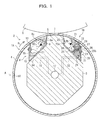
- FIG. 1 shows an oil recovery apparatus for a roll apparatus as a first embodiment of the present invention and is a sectional view of a roll apparatus taken along a plane perpendicular to the roll axial direction;
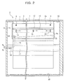
- FIG. 2 shows the oil recovery apparatus for a roll apparatus as the first embodiment of the present invention and is a view as viewed in the direction indicated by an arrow mark A of FIG. 1 (with a roll mangle shown in section) ;
- FIG. 3 is a schematic view showing an example wherein the oil recovery apparatus for a roll apparatus according to the first embodiment of the present invention is applied to another roll apparatus;
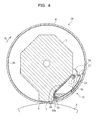
- FIG. 4 shows an oil recovery apparatus for a roll apparatus as a second embodiment of the present invention and is a sectional view of a roll apparatus taken along a plane perpendicular to the roll axial direction;
- FIG. 5A shows an oil recovery apparatus for a roll apparatus as a third embodiment of the present invention and is a sectional view of a roll apparatus taken along a plane perpendicular to the roll axial direction;
- FIG. 5B shows the oil recovery apparatus for a roll apparatus as the third embodiment of the present invention and is an enlarged view of part of the oil recovery apparatus for a roll apparatus;
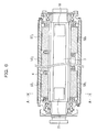
- FIG. 6 is an axial sectional view showing an example of a popular S.L.C.C.R (self loading controlled crown roll);
- FIG. 7 shows an oil recovery apparatus for a roll apparatus as a fourth embodiment of the present invention and is a sectional view taken along line A-A of FIG. 6;
- FIG. 8 is a schematic view showing a contact control apparatus according to the fourth embodiment of the present invention;
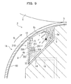
- FIG. 9 is a similar view but showing another contact control apparatus according to the fourth embodiment of the present invention;
- FIG. 10 shows a conventional oil recovery apparatus for a roll apparatus and is a sectional view of a roll apparatus taken along a plane perpendicular to the roll axial direction; and
- FIG. 11 is a schematic view illustrating a subject of the conventional oil recovery apparatus for a roll apparatus.
- In the following, embodiments of the present invention are described with reference to the drawings.
- FIGS. 1 and 2 show an oil recovery apparatus for a roll apparatus as a first embodiment of the present invention. More particularly, FIG. 1 is a sectional view of a roll apparatus taken along a plane perpendicular to the roll axial direction, and FIG. 2 is a view as viewed in the direction indicated by an arrow mark A of FIG. 1 (with a roll mangle shown in section). It is to be noted that, in FIG. 1, an arrow mark R1 indicates the direction of rotation of a roll mantle.
- A pair of roll apparatus
oil recovery apparatus roll apparatus 2 which is provided typically in a press apparatus or a calendar apparatus of a paper machine. Theroll apparatus 2 is described first. Referring particularly to FIG. 1, theroll apparatus 2 includes, as principal components thereof, a stationary center shaft (support member) 3 extending in the roll axial direction (apparatus widthwise direction), acylindrical roll mantle 4 disposed around an axis of thecenter shaft 3 in such a manner as to cover thecenter shaft 3 and driven to rotate by a driving apparatus not shown provided at an axial end portion, and ashoe 5 supported at an upper portion of thecenter shaft 3 for pressing theroll mantle 4 in a circumferentially outer direction from the inner circumference side. - It is to be noted that the
shoe 5 may be divided into a plurality of parts in the roll axis direction such that the pressing force of each of the divisional parts of theshoe 5 may be adjusted independently so as to form theroll apparatus 2 as a multi-shoe type controlled crown roll (M.C.C.R) wherein the outer profile of theroll mantle 4 in the axial direction can be controlled (crown control) . Meanwhile, theroll mantle 4 may be of the rotationally driving type which itself receives and is rotated by rotational driving force or may alternatively be of the driven type. - FIGS. 1 and 2 show a model of the
roll apparatus 2 to which the roll apparatusoil recovery apparatus center shaft 3 is shown having a generally hexagonal shape in FIGS. 1 and 2, the shape of thecenter shaft 3 is not limited to the specific shape, but thecenter shaft 3 may have any shape. Further, while a detailed configuration of theshoe 5 is not shown in FIGS. 1 and 2, theshoe 5 may be configured, for example, similarly to the shoe of the prior art described hereinabove. Further, in the present embodiment, theroll apparatus 2 is shown disposed below anopposed roll 6 as seen in FIGS. 1 and 2. - In such a
roll apparatus 2 as described above, oil (lubricating oil) 50 is supplied into the inside of theroll mantle 4 to form an oil film on acontact portion 7 in order to reduce the coefficient of friction between thecontact portion 7 of theshoe 5 and the inner circumferential face of theroll mantle 4 thereby to allow theroll mantle 4 to rotate smoothly. However, if the speed of rotation of theroll mantle 4 is high, then theoil 50 inside theroll mantle 4 collides violently with thecontact portion 7 and rebounds as reversing current in the form of oil spray over a region on the upstream side in the direction of rotation of theroll mantle 4 as indicated by an arrow mark R3 in FIG. 1. - The roll apparatus
oil recovery apparatus 1A is configured such that it efficiently recovers theoil 50 after theoil 50 collides violently with thecontact portion 7 and rebounds to the upstream side in the direction of rotation as described above. More particularly, the roll apparatusoil recovery apparatus 1A includes an oil recovery pan (first oil recovery pan) 8 provided below thecontact portion 7 on the upstream side in the direction of rotation of theroll mantle 4 with respect to thecontact portion 7 and serving as an oil receiving pan. Theoil recovery pan 8 has an opening formed in a size sufficient to catch substantially all of theoil 50 colliding with and rebounding from thecontact portion 7. Further, theoil recovery pan 8 extends in the roll axial direction and is attached at a oneside portion 8a thereof to thecenter shaft 3 by means ofbolts 9. - Particularly, as seen in FIG. 1, an oil scattering preventing plate (oil scattering preventing member) 10 is attached to the
other side portion 8b of theoil recovery pan 8 and extends in the roll axial direction. The oilscattering preventing plate 10 is attached such that an upper end portion (outer edge upper end portion) 12 thereof is positioned closely to the inner circumference of theroll mantle 4 within a range within which theupper end portion 12 does not interfere with the oil film entrained inside theroll mantle 4. Further, as seen in FIG. 2, bolt holes at theother side portion 8b of theoil recovery pan 8 to which the oilscattering preventing plate 10 is attached are each formed as anelongated hole 13 extending toward the inner circumferential face of theroll mantle 4. Although the thickness of the oil film normally varies depending upon the operation conditions and so forth, since the oilscattering preventing plate 10 can be adjusted toward and away from the inner circumferential face of theroll mantle 4 through suchelongated holes 13 as described above, the oilscattering preventing plate 10 can be adjusted to a suitable position corresponding to the thickness of the oil film. - As seen in FIGS. 1 and 2, an
oil drain port 14 is formed at a bottom portion of theoil recovery pan 8, and aninclined plate 15 is provided at the bottom portion of theoil recovery pan 8 such that it is inclined in the roll axial direction in order that theoil 50 recovered by theoil recovery pan 8 may be guided readily into theoil drain port 14. Further, apipe 16 connecting to theoil drain port 14 and anotherpipe 17 connecting to thepipe 16 and extending in the axial direction of thecenter shaft 3 for discharging theoil 50 to the outside of theroll apparatus 2 are formed in thecenter shaft 3. Thus, theoil 50 recovered by theoil recovery pan 8 flows along theinclined plate 15 into theoil drain port 14, passes through thepipe 16 and thepipe 17, and is discharged to the outside of theroll apparatus 2 as indicated by an arrow mark R4 in FIG. 2. It is to be noted that theoil 50 discharged to the outside of theroll apparatus 2 in this manner undergoes suitable processing such as cooling and is thereafter supplied into theroll mantle 4 through anoil supply port 18 formed at an axial end portion of thecenter shaft 3 and theshoe 5 as indicated by an arrow mark R4' in FIG. 2. - Meanwhile, as seen in FIG. 1, the roll apparatus
oil recovery apparatus 1B includes, as principal components thereof, an oil recovery pan (second oil recovery pan) 20 provided below thecontact portion 7 on the downstream side in the direction of rotation of theroll mantle 4 with respect to thecontact portion 7 for recovering theoil 50 entrained inside theroll mantle 4 as theroll mantle 4 rotates, and ascraping blade 22 provided above theoil recovery pan 20 and having anend portion 21 held in contact with the inner circumferential face of theroll mantle 4 to scrape off theoil 50 entrained inside theroll mantle 4 and introducing the scrapedoil 50 into theoil recovery pan 20. - The
oil recovery pan 20 has an opening formed in a size sufficient to catch substantially all of theoil 50 scraped off by thescraping blade 22. Further, theoil recovery pan 20 extends in the roll axial direction and is attached at a oneside portion 20a thereof to thecenter shaft 3 by means ofbolts 23. - Meanwhile, the
scraping blade 22 extends in the roll axial direction. Further, anadjustment mechanism 30 for adjusting the pressing force of theend portion 21 of thescraping blade 22 against the inner circumferential face of theroll mantle 4 is provided. Theadj ustment mechanism 30 includes afirst support member 25 attached to the inner side of theother side portion 20b of theoil recovery pan 20 by means ofbolts 24, arubber tube 26 attached to an upper portion of thefirst support member 25, and asecond support member 28 attached to an upper portion of therubber tube 26 by means ofbolts 27. Thescraping blade 22 is attached to an upper portion of thesecond support member 28. - Though not shown, bolt holes in the
second support member 28 are each formed from an elongated hole extending in the upward and downward directions in FIG. 1, and thebolts 27 are fitted loosely in the bolt holes. Consequently, thesecond support member 28 can be moved over a distance equal to the length (predetermined distance) of the bolt holes in the upward and downward directions. In particular, the pressure of compressible fluid such as air in therubber tube 26 is controlled so that therubber tube 26 may function as an air spring to adjustably support thesecond support member 28 in the upward and downward directions thereby to resiliently softly press thescraping blade 22 against the inner circumferential face of theroll mantle 4. It is to be noted that thescraping blade 22 is removably mounted on thesecond support member 28 so that thescraping blade 22 can be replaced readily if theend portion 21 thereof is abraded. - Further, an
oil drain port 29 is formed at a bottom portion of theoil recovery pan 20, and aninclined plate 31 is provided at the bottom portion of theoil recovery pan 20 such that it is inclined in the roll axial direction so that theoil 50 recovered by theoil recovery pan 20 may be introduced readily into theoil drain port 29. Further, apipe 32 connecting to theoil drain port 29 is formed in thecenter shaft 3 and connected to thepipe 17. Consequently, theoil 50 recovered by theoil recovery pan 20 flows into theoil drain port 29 along theinclined plate 31, passes through thepipe 32 and thepipe 17 and is discharged to the outside of theroll apparatus 2. - The oil recovery apparatus for a roll apparatus as the first embodiment of the present invention is configured in such a manner as described above. Consequently, the roll apparatus
oil recovery apparatus 1A can recover also theoil 50, which has collided violently with thecontact portion 7 and rebounded over a region on the upstream side in the direction of rotation of theroll mantle 4, efficiently and with certainty without interfering with the oil film formed from theoil 50 entrained inside theroll mantle 4. In short, also when theroll mantle 4 rotates at a high speed, a high oil recovery ratio can be achieved. - Further, with the roll apparatus
oil recovery apparatus 1B, since theoil 50 on the inner circumference of theroll mantle 4 is scraped off by thescraping blade 22 which contacts resiliently softly with the inner circumferential face of theroll mantle 4, the oil film on the inner circumference of theroll mantle 4 can be recovered satisfactorily without having a bad influence such as damage on the inner face of theroll mantle 4. Thus, also when theroll mantle 4 rotates at a high speed, the roll apparatusoil recovery apparatus 1B can recover the oil with an improved oil recovery ratio similarly to the effect of the roll apparatusoil recovery apparatus 1A. - It is to be noted that, while, in the present embodiment, both of the roll apparatus
oil recovery apparatus 1A and the roll apparatusoil recovery apparatus 1B are provided, also it is possible to provide only one of the roll apparatusoil recovery apparatus 1A and the roll apparatusoil recovery apparatus 1B. - FIG. 3 shows an example wherein the roll apparatus
oil recovery apparatus 1A is applied to a roll apparatus 2' different from theroll apparatus 2 described hereinabove. The roll apparatusoil recovery apparatus 1A' shown in FIG. 3 has a configuration substantially similar to that of the roll apparatusoil recovery apparatus 1A according to the first embodiment described hereinabove. In particular, an upper end portion 12' of an oil scattering preventing plate 10' extends to a position close to the inner circumferential face of theroll mantle 4 within a range within which the upper end portion 12' does not interfere with the oil film. Further, theoil 50 recovered by an oil recovery pan 8' is discharged to the outside of the roll apparatus 2' through an oil drain port 14'. Furthermore, while detailed description of theshoe 5 in the first embodiment is omitted hereinabove, a shoe 5' according to the roll apparatus 2' is driven in the upward and downward directions by hydraulic fluid supplied into apressure chamber 36 through a hydraulicfluid supply pipe 35. The roll apparatusoil recovery apparatus 1A' can be applied also to the roll apparatus 2' having such a configuration as described above, and a similar effect to that of the first embodiment, that is, an effect that also theoil 50, which has collided violently with thecontact portion 7 and rebounded over a region on the upstream side in the direction of rotation of theroll mantle 4, can be recovered efficiently and with certainty can be achieved. - FIG. 4 shows an oil recovery apparatus for a roll apparatus as a second embodiment of the present invention and shows a sectional view of a roll apparatus taken along a plane perpendicular to the roll axial direction. It is to be noted that like portions and elements to those of the first embodiment (FIGS. 1 and 2) described hereinabove are denoted by like reference characters.
- The roll apparatus oil recovery apparatus 1C according to the present embodiment is incorporated in a
roll apparatus 2A provided above anopposed roll 6. First, description is given of theroll apparatus 2A. Referring to FIG. 4, theroll apparatus 2A includes, as principal components thereof, a stationary center shaft (support member) 3 extending in the roll axial direction (apparatus widthwise direction), acylindrical roll mantle 4 disposed around an axis of thecenter shaft 3 in such a manner as to cover thecenter shaft 3 for being driven to rotate by a driving apparatus not shown provided at an axial end portion of thecenter shaft 3, and ashoe 5 supported at a lower portion of thecenter shaft 3 for pressing theroll mantle 4 in a circumferentially outward direction from the inner circumference side. It is to be noted that, in FIG. 4, a model of theroll apparatus 2A to which the roll apparatus oil recovery apparatus 1C is applied is shown. Accordingly, while thecenter shaft 3 is shown having, for example, a generally hexagonal shape in FIG. 4, the shape of thecenter shaft 3 is not limited to the specific shape, but thecenter shaft 3 may have any shape. Further, while a detailed configuration of theshoe 5 is not shown in FIG. 4, theshoe 5 may be configured, for example, similarly to the shoe of the prior art described hereinabove. - In such a
roll apparatus 2A as described above, oil (lubricating oil) 50 is supplied into theroll mantle 4 to form an oil film on thecontact portion 7 in order to reduce the coefficient of friction between thecontact portion 7 of theshoe 5 and the inner circumferential face of theroll mantle 4 thereby to allow theroll mantle 4 to rotate smoothly. However, if the speed of rotation of theroll mantle 4 is high, then theoil 50 inside theroll mantle 4 collides violently with thecontact portion 7 and rebounds over a region on the upstream side in the direction of rotation of theroll mantle 4 as described hereinabove. - The roll apparatus oil recovery apparatus 1C is configured such that it efficiently recovers the
oil 50 after theoil 50 collides violently with thecontact portion 7 and rebounds to the upstream side in the direction of rotation as described above similarly to the roll apparatusoil recovery apparatus 1A according to the first embodiment. More particularly, the roll apparatus oil recovery apparatus 1C includes, as principal components thereof, an oil recovery pan (oil recovery flow path) 55 supported on thecenter shaft 3 and provided inside theroll mantle 4, a siphonflowpath 54 having anopening 54a on the upstream side in the direction of rotation of theroll mantle 4 with respect to thecontact portion 7 and utilizing a pressure difference from the pressure inside theroll mantle 4 produced by damming up theoil 50 entrained inside theroll mantle 4 upon rotation of theroll mantle 4 at theshoe 5 to change the dynamic pressure of theoil 50 into static pressure to recover and introduce theoil 50 into theoil recovery pan 55, and an oil introducingflow path 53 for guiding theoil 50 so as to be introduced with certainty to a location in the proximity of theopening 54a of the siphonflow path 54. - The
oil recovery pan 55 is disposed on the upstream side in the direction of rotation of theroll mantle 4 with respect to thecontact portion 7 and extends in the roll axial direction. Further, theoil recovery pan 55 has faces which extend along the inner circumferential face of theroll mantle 4, a side face of the shoe 5 (a face on the upstream side in the direction of rotation of the roll mantle 4) and a side face of the center shaft 3 (a face on the upstream side in the direction of rotation of the roll mantle 4). The oil introducingflow path 53 is formed from a space defined by theoil recovery pan 55 having such a configuration as described above and the inner circumferential face of theroll mantle 4, and the siphonflow path 54 is formed from another space defined by theoil recovery pan 55,shoe 5 andcenter shaft 3. - At a position opposing to the exit of the siphon
flow path 54, acover member 56 is provided for preventing scattering of theoil 50 blowing out from the exit of the siphonflow path 54 so that theoil 50 is recovered with certainty into theoil recovery pan 55. Thecover member 56 is formed with a length in the axial direction equal to that of theoil recovery pan 55 and attached to theoil recovery pan 55 by means ofbolts 57. Anoil drain port 58 for discharging theoil 50 recovered by theoil recovery pan 55 to the outside of theroll apparatus 2A is provided in a bottom portion of theoil recovery pan 55. It is to be noted that theoil 50 discharged to the outside of theroll apparatus 2A is supplied into and circulated in theroll mantle 4 after it undergoes a suitable process such as cooling. - The roll apparatus oil recovery apparatus 1C as the second embodiment of the present invention is configured in such a manner as described above. Therefore, the
oil 50 entrained inside theroll mantle 4 is introduced on the upstream side in the direction of rotation of theroll mantle 4 with respect to thecontact portion 7 into the oil introducingflow path 53 and then dammed by theshoe 5, whereupon the dynamic pressure thereof is converted into a static pressure. Consequently, a pressure higher than the water head pressure of the siphonflow path 54 is generated at theopening 54a, and this pressure causes theoil 50 to flow from theopening 54a of the siphonflow path 54 into and through the siphonflow path 54 until it is recovered into theoil recovery pan 55. - In this manner, according to the roll apparatus oil recovery apparatus 1C, the
oil 50 can be recovered efficiently and with certainty without allowing theoil 50 to collide violently with thecontact portion 7. In short, also when theroll mantle 4 rotates at a high speed, the roll apparatus oil recovery apparatus 1C can assure a high oil recovery ratio similarly as in the first embodiment. - FIGS. 5A and 5B show an oil recovery apparatus for a roll apparatus as a third embodiment of the present invention, and particularly, FIG. 5A is a sectional view of a roll apparatus taken along a plane perpendicular to the roll axial direction while FIG. 5B is an enlarged view of part of the roll apparatus. It is to be noted that like portions and elements to those of the first embodiment (FIGS. 1 and 2) described hereinabove are denoted by like reference characters.
- The roll apparatus
oil recovery apparatus 1D according to the present embodiment is incorporated in aroll apparatus 2 provided below anopposed roll 6 similarly as in the first embodiment. Theroll apparatus 2 has a configuration similar to that in the first embodiment, and therefore, overlapping description of the configuration of theroll apparatus 2 is omitted herein to avoid redundancy. - As shown in FIG. 5A, the roll apparatus
oil recovery apparatus 1D includes anoil recovery member 60 attached to a lower portion of thecenter shaft 3 on the downstream side in the direction of rotation of theroll mantle 4 by means ofbolts 66 and held in contact at anend portion 62 thereof with the inner circumferential face of theroll mantle 4. As shown in FIG. 5B, theoil recovery member 60 extends in the roll axial direction, and an oilrecovery flow path 63 is formed inside theoil recovery member 60 and extends in the roll axial direction. Further, the oilrecovery flow path 63 is connected to the outside of theroll apparatus 2. - An oil recovering
wedge forming face 64 is formed at theend portion 62 of theoil recovery member 60 and disposed such that it gradually approaches the inner circumferential face of theroll mantle 4 toward the downstream in the flowing direction of theoil 50 entrained inside theroll mantle 4 as theroll mantle 4 rotates. A plurality ofopenings 65 are formed in a juxtaposed relationship in the roll axial direction on the oil recoveringwedge forming face 64. Further, communicatingflow paths 61 are formed inside theoil recovery member 60 for recovering theoil 50 entrained inside theroll mantle 4 through theopenings 65 and introducing theoil 50 into the oilrecovery flow path 63 by a wedge effect generated in a wedge-shaped space defined by the inner circumferential face of theroll mantle 4 and the oil recoveringwedge forming face 64. - The gap between the oil recovering
wedge forming face 64 and the inner circumferential face of theroll mantle 4 is set such that an upstream portion thereof is greater than the thickness of the oil film (that is, greater than or substantially equal to the thickness of the oil film [refer to reference character D1 in FIG. 5B]) while a downstream portion thereof is smaller than the thickness of the oil film (that is, smaller than D1). It is to be noted that the thickness of the oil film here is the thickness of the oil film advancing into the gap described above and is preferably set particularly in accordance with the thickness of the oil film when theroll mantle 4 rotates at a high speed. Further, while it is described above that a plurality ofopenings 65 are formed along the roll axial direction in the oil recoveringwedge forming face 64, naturally a slit-shaped opening may otherwise be formed along the roll axial direction. - The roll apparatus
oil recovery apparatus 1D as the third embodiment of the present invention is configured in such a manner as described above. Therefore, theoil 50 entrained inside theroll mantle 4 enters the wedge-shaped space between the oil recoveringwedge forming face 64 of theoil recovery member 60 and the inner circumferential face of theroll mantle 4 and is acted upon, in the wedge-shaped space, by pressure generated by the wedge-effect of the wedge-shaped space, whereafter it is recovered into the oilrecovery flow path 63 from theopenings 65 through the communicatingflow paths 61 and then discharged to the outside of theroll apparatus 2 from the oilrecovery flow path 63. - In this manner, with the roll apparatus
oil recovery apparatus 1D, theoil 50 entrained inside theroll mantle 4 can be recovered efficiently and with certainty making use of the pressure generated by the wedge-effect of the wedge-shaped space defined between the oil recoveringwedge forming face 64 of theoil recovery member 60 and the inner circumferential face of theroll mantle 4. In short, also when theroll mantle 4 rotates at a high speed, the roll apparatusoil recovery apparatus 1D can assure an improved oil recovery efficiency similarly as in the first embodiment. - Further, since the gap between the oil recovering
wedge forming face 64 and the inner circumferential face of theroll mantle 4 is set such that an upstream portion thereof is greater than the thickness of the oil film while a downstream portion thereof is smaller than the thickness of the oil film, theoil 50 can be introduced smoothly into the wedge-shaped space defined by the inner circumferential face of theroll mantle 4 and the oil recoveringwedge forming face 64. - FIG. 6 is an axial sectional view showing an example of a popular S.L.C.C.R (self loading controlled crown roll), and FIG. 7 shows oil recovery apparatus for a roll apparatus as a fourth embodiment of the present invention and is a sectional view taken along line A-A of FIG. 6. It is to be noted that FIG. 6 shows an S. L. C. C. R disposed below an opposed roll (not shown), and an arrow mark R1 shown in FIG. 7 indicates the direction of rotation of a
roll mantle 4. Further, in FIGS. 6 and 7, like portions and elements to those of the first embodiment (FIGS. 1 and 2) described hereinabove are denoted by like reference characters. - Referring first to FIG. 6, the S.L.C.C.R includes a plurality of
shoes 5 provided on the opposite upper and lower sides of acenter shaft 3. The S.L.C.C.R shown in FIG. 6 particularly includes three shoes 5T1, 5T2, 5T3 provided on the upper side of thecenter shaft 3 and two shoes 5B1, 5B2 provided on the lower side of thecenter shaft 3. In the S.L.C.C.R having the configuration just described, the shoes 5T1, 5T2, 5T3 can be driven hydraulically or the like to move in upward and downward directions separately from one another. As theroll mantle 4 can be moved upwardly or downwardly by the shoes 5T1, 5T2, 5T3 configured in this manner thereby to form a nip between theroll mantle 4 and theopposed roll 6, an arm mechanism for moving the entire roll upwardly and downwardly is not required. Further, by adjusting the pressure distribution to the shoes 5T1, 5T2, 5T3, the pressing force to theroll mantle 4 can be adjusted finely in the roll axial direction, and consequently, a nip pressure variation caused by deflection of thecenter shaft 3 or a crown shape of theroll mantle 4 can be corrected. Also the shoes 5B1, 5B2 can be driven hydraulically or the like to move in upward and downward directions separately from each other similarly to the shoes 5T1, 5T2, 5T3. - Where the oil pressure to act upon the shoe 5T2 is set higher than the oil pressure to act upon the shoes 5T1, 5T3 so that the
roll mantle 4 has a crown shape (convex shape), the oil pressure to act upon the shoes 5B1, 5B2 is set higher to drive the shoes 5B1, 5B2 to move in the downward direction in FIG. 6 so that a load is applied to the opposite axial ends of the roll to apply bending moment, by which a desired crown shape can be obtained. On the other hand, where the oil pressure to act upon the shoe 5T2 is set lower than the oil pressure to act upon the shoes 5T1, 5T3 so that theroll mantle 4 has a discrown shape (concave shape), the oil pressure to act upon the shoes 5B1, 5B2 is set lower to drive the shoes 5B1, 5B2 to move in the upward direction in FIG. 6, by which a desired discrown shape can be obtained. Consequently, the nip pressure to theopposed roll 6 can be controlled while preventing the cross sectional shape of theroll mantle 4 from being deformed excessively. It is to be noted that the S.L.C.C.R having such a configuration as described above is used as a center roll of a press apparatus or a calendar roll of a calendar apparatus of a paper machine. - The present oil recovery apparatus for a roll apparatus are applied to the S.L.C.C.R having such a configuration as described above and have configurations similar to those of the roll apparatus
oil recovery apparatus oil recovery apparatus 1A extending in the roll axial direction is attached to the upstream side in the direction of rotation with respect to the shoe 5T1, and another roll apparatusoil recovery apparatus 1B extending in the roll axial direction is attached to the downstream side in the direction of rotation with respect to the shoe 5T1. - In this manner, the roll apparatus
oil recovery apparatus 1A and the roll apparatusoil recovery apparatus 1B can be applied also to the S.L.C.C.R and can recover also theoil 50, which has collided violently with thecontact portion 7 and rebounded over a region on the upstream side in the direction of rotation of theroll mantle 4, efficiently and with certainty without interfering with the oil film formed from theoil 50 entrained inside theroll mantle 4. In short, also when theroll mantle 4 rotates at a high speed, a high oil recovery ratio can be achieved. Further, since theoil 50 on the inner circumference of theroll mantle 4 is scraped off by thescraping blade 22 which contacts resiliently softly with the inner circumferential face of theroll mantle 4, the oil on the inner circumference of theroll mantle 4 can be recovered satisfactorily without having a bad influence such as damage on the inner face of theroll mantle 4. Thus, also when theroll mantle 4 rotates at a high speed, the oil can be recovered with an improved oil recovery ratio similarly to the effect of the roll apparatusoil recovery apparatus 1A. - It is to be noted that, while, in the S.L.C.C.R, the gap between the oil
scattering preventing plate 10 of the roll apparatusoil recovery apparatus 1A and theroll mantle 4 sometimes becomes greater as theroll mantle 4 moves upwardly or downwardly or the crown shape changes, since the oilscattering preventing plate 10 is provided, the oil recovery ratio can be improved when compared with the prior art. Further, in this instance, a contact control apparatus (contact control means) for moving the oilscattering preventing plate 10 into and out of contact with theroll mantle 4 may be provided to adj ust the distance of the oilscattering preventing plate 10 from theroll mantle 4. Where the configuration just described is employed, the oil recovery ratio can be improved with a higher degree of certainty. For example, as shown in FIG. 8, acontact control apparatus 110 is provided which includes aguide 100 secured to the oilscattering preventing plate 10 for engaging with theother side portion 8b of theoil recovery pan 8, one or a plurality ofracks 101 secured to the oilscattering preventing plate 10, asupport base 102 secured to theother side portion 8b of theoil recovery pan 8, support posts 103 provided uprightly on thesupport base 102, and a pinion orpinions 104 attached for rotation on the support posts 103 and held in engagement with the rack or racks 101. According to thecontact control apparatus 110 having the configuration just described, by rotating the pinion orpinions 104, the oilscattering preventing plate 10 can be slidably moved in upward and downward directions along theother side portion 8b of theoil recovery pan 8, and theupper end portion 12 of the oilscattering preventing plate 10 can be suitably brought into or out of contact with the inner circumferential face of theroll mantle 4. Alternatively, for example, acontact control apparatus 210 may be provided as seen in FIG. 9 which includes aguide 200 secured to the oilscattering preventing plate 10 for engaging with theother side portion 8b of theoil recovery pan 8, aposition adjustment plate 201 secured to the oilscattering preventing plate 10, asupport base 202 secured to theother side portion 8b of theoil recovery pan 8, and a tube member (for example, a rubber tube) 203 disposed between theposition adjustment plate 201 and thesupport base 202 for expanding and contracting movement by air or oil supplied thereto from the outside. According to thecontact control apparatus 210 having the configuration just described, if the air pressure or the oil pressure inside the tube member 203 is adjusted to vary the diameter of the tube member 203, then the oilscattering preventing plate 10 can be slidably moved in an upward or downward direction along theother side portion 8b of theoil recovery pan 8 to suitably place theupper end portion 12 of the oilscattering preventing plate 10 into and out of the inner circumferential face of theroll mantle 4. It is to be noted that, whilereference numeral 204 shown in FIG. 9 denotes a holding plate forpreventingthetubemember203frombeingletoffthesupport base 202, where there is no possibility that the tube member 203 may be let off, the holdingplate 204 need not be provided. Further, the configuration of the contact control apparatus is not limited to those described above. - While, in the present embodiment, the roll apparatus
oil recovery apparatus oil recovery apparatus - While preferred embodiments of the present invention have been described using specific terms, the present invention is not limited to the embodiments specifically described above, and variations and modifications can be made without departing from the scope of the present invention. For example, the
roll apparatus 2 according to the first embodiment may be configured otherwise such that it includes the roll apparatusoil recovery apparatus 1D in addition to the roll apparatusoil recovery apparatus - Further, the
roll apparatus 2 according to the first embodiment may be configured otherwise such that it includes only the roll apparatusoil recovery apparatus 1A without provision of the roll apparatusoil recovery apparatus 1B but additionally includes the roll apparatusoil recovery apparatus 1D according to the third embodiment. - Furthermore, the
roll apparatus 2A according to the second embodiment may be configured otherwise such that it includes the roll apparatusoil recovery apparatus 1D according to the third embodiment in addition to the roll apparatus oil recovery apparatus 1C. - Further, while, in the first and third embodiments described above, the
roll apparatus 2 includes theshoe 5 provided at an upper portion of thecenter shaft 3, where theroll apparatus 2 is configured otherwise such that another shoe is provided also at a lower portion of thecenter shaft 3, for example, as in the S.L.C.C.R of the fourth embodiment, the roll apparatus oil recovery apparatus 1C according to the second embodiment may be provided on the upstream side in the direction of rotation of theroll mantle 4 with respect to the lower portion of thecenter shaft 3.
Claims (5)
- An oil recovery apparatus for a roll apparatus which includes
a stationary support member (3),
a roll mantle (4) disposed around and rotated on a circumference of said support member (3), and
a shoe (5) supported on said support member (3) for pressing said roll mantle (4) in an outer circumferential direction from the inner circumference side, said shoe (5) having a contact portion (7) positioned at a lower portion inside said roll mantle (4), which contact portion (7) is adapted to be in contact with said roll mantle (4),
said oil recovery apparatus being provided for said roll apparatus for recovering oil inside said roll mantle (4), said oil recovery apparatus comprising:an oil recovery flow path (55) supported on said support member (3) and provided inside said roll mantle (4); anda siphon flowpath (54) having an opening (54a) opened on the upstream side with respect to said contact portion (7) in the direction of rotation of said roll mantle (4) for recovering the oil entrained inside said roll mantle (4) upon rotation of said roll mantle (4) through said opening (54a) and introducing the recovered oil into said oil recovery flow path (55) making use of a pressure difference. - The oil recovery apparatus for a roll apparatus as claimed in claim 1, wherein the lower portion inside said roll mantle (4) at which said contact portion (7) is positioned is the inner circumferential face of said roll mantle (4) below a horizontal plane including an axial line of said roll mantle (4).
- The oil recovery apparatus for a roll apparatus as claimed in claim 1 or 2, further comprising an oil introducing flow path (53) for introducing the oil to a location proximate to said opening (54a) of said siphon flow path (54).
- An oil recovery apparatus for a roll apparatus which includes
a stationary support member (3),
a roll mantle (4) disposed around and rotated on a circumference of said support member (3), and
a shoe (5) supported on said support member (3) for pressing said roll mantle (4) in an outer circumferential direction from the inner circumference side,
said oil recovery apparatus being provided for said roll apparatus for recovering oil inside said roll mantle (4), said oil recovery apparatus comprising:an oil recover flow path (63) supported on said support member (3) and provided inside said roll mantle (4);an oil recovering wedge forming face (64) supported on said support member (3) and disposed so as to gradually approach the inner circumferential face of said roll mantle (4) toward the downstream in a flowing direction of the oil entrained inside said roll mantle (4) upon rotation of said roll mantle (4); anda communicating flow path (61) having an opening (65) opened to said oil recovering wedge forming face (64) for recovering the oil entrained inside said roll mantle (4) through said opening (65) and introducing the recovered oil into said oil recover flow path (63) making use of a wedge effect provided by a wedge-shaped space defined by the inner circumferential face of said roll mantle (4) and said oil recovering wedge forming face (64). - The oil recovery apparatus for a roll apparatus as claimed in claim 4, wherein a gap between said oil recovering wedge forming face (64) and the inner circumferential face of said roll mantle (4) is set, at an upstream portion thereof, greater than or substantially equal to the thickness of an oil film formed from the oil entrained inside said roll mantle (4), but set, at a downstream portion thereof, smaller than the thickness of the oil film.
Applications Claiming Priority (2)
| Application Number | Priority Date | Filing Date | Title |
|---|---|---|---|
| JP2004030933A JP2005221027A (en) | 2004-02-06 | 2004-02-06 | Oil collecting device for roll device |
| EP04029734A EP1561959B1 (en) | 2004-02-06 | 2004-12-15 | Roll apparatus with oil recovery apparatus |
Related Parent Applications (1)
| Application Number | Title | Priority Date | Filing Date |
|---|---|---|---|
| EP04029734A Division EP1561959B1 (en) | 2004-02-06 | 2004-12-15 | Roll apparatus with oil recovery apparatus |
Publications (2)
| Publication Number | Publication Date |
|---|---|
| EP1734267A1 true EP1734267A1 (en) | 2006-12-20 |
| EP1734267B1 EP1734267B1 (en) | 2009-07-01 |
Family
ID=34675565
Family Applications (2)
| Application Number | Title | Priority Date | Filing Date |
|---|---|---|---|
| EP04029734A Ceased EP1561959B1 (en) | 2004-02-06 | 2004-12-15 | Roll apparatus with oil recovery apparatus |
| EP06121337A Ceased EP1734267B1 (en) | 2004-02-06 | 2004-12-15 | Roll apparatus with oil recovery apparatus |
Family Applications Before (1)
| Application Number | Title | Priority Date | Filing Date |
|---|---|---|---|
| EP04029734A Ceased EP1561959B1 (en) | 2004-02-06 | 2004-12-15 | Roll apparatus with oil recovery apparatus |
Country Status (5)
| Country | Link |
|---|---|
| US (1) | US7575544B2 (en) |
| EP (2) | EP1561959B1 (en) |
| JP (1) | JP2005221027A (en) |
| CN (4) | CN1651778A (en) |
| DE (2) | DE602004022770D1 (en) |
Families Citing this family (3)
| Publication number | Priority date | Publication date | Assignee | Title |
|---|---|---|---|---|
| DE102006034043A1 (en) * | 2006-07-24 | 2008-01-31 | Voith Patent Gmbh | press roll |
| DE202010014965U1 (en) | 2010-10-30 | 2011-01-05 | Andritz Küsters Gmbh | deflection |
| CN109706663A (en) * | 2019-03-05 | 2019-05-03 | 南充八度阳光科技有限公司 | A kind of flux controllable oiling device for carbon fiber production |
Citations (7)
| Publication number | Priority date | Publication date | Assignee | Title |
|---|---|---|---|---|
| US4741079A (en) * | 1985-11-22 | 1988-05-03 | Clecim | Roll with a rotating shell |
| DE4402754A1 (en) * | 1994-01-31 | 1994-06-16 | Voith Gmbh J M | Pressure element - with collector unit in oil siphon system which is mounted at points least influenced by beam deflections |
| JPH1082416A (en) | 1996-06-13 | 1998-03-31 | Voith Sulzer Papiermas Gmbh | Deflection adjusting roll |
| US5878507A (en) * | 1995-09-18 | 1999-03-09 | Voith Sulzer Papiermaschinen Gmbh | Apparatus for a paper-making machine for delivering liquid from a first level to a second, higher level |
| WO2001042560A1 (en) * | 1999-12-08 | 2001-06-14 | Metso Paper Karlstad Aktiebolag | Method and device for oil evacuation from a shoe press unit |
| US6454685B1 (en) * | 1999-07-06 | 2002-09-24 | Metso Paper, Inc. | Method and arrangement for removing oil from a roll |
| DE10154862A1 (en) * | 2001-11-08 | 2003-05-22 | Voith Paper Patent Gmbh | Device for draining liquid |
Family Cites Families (7)
| Publication number | Priority date | Publication date | Assignee | Title |
|---|---|---|---|---|
| US5189775A (en) * | 1992-02-25 | 1993-03-02 | The Black Clawson Company | Zone controlled deflection compensated roll |
| DE4420104C2 (en) | 1994-06-09 | 1997-04-24 | Voith Sulzer Papiermasch Gmbh | Support element |
| DE19616802A1 (en) * | 1996-04-26 | 1997-10-30 | Voith Sulzer Papiermasch Gmbh | Deflection compensation roller |
| DE19703966A1 (en) | 1997-02-03 | 1998-08-06 | Voith Sulzer Papiermasch Gmbh | Belt press unit with fluid wiping device and method for operating the belt press unit |
| FI2920U1 (en) * | 1997-02-28 | 1997-05-29 | Valmet Corp | Arrangement on a deflection-compensated roller with load shoes |
| FI114334B (en) | 1998-09-23 | 2004-09-30 | Metso Paper Inc | Plant in connection with a bombable roller and a method for regulating the flow of oil in connection with a bombable roller |
| DE19903843C1 (en) | 1999-02-01 | 2000-07-06 | Voith Sulzer Papiertech Patent | Roller for a web processing machine has inner supports at the cylinder mantle and scraper lips on levers with a take-off channel for the fluid leading to an offset collection zone |
-
2004
- 2004-02-06 JP JP2004030933A patent/JP2005221027A/en active Pending
- 2004-12-03 US US11/002,123 patent/US7575544B2/en not_active Expired - Fee Related
- 2004-12-15 EP EP04029734A patent/EP1561959B1/en not_active Ceased
- 2004-12-15 EP EP06121337A patent/EP1734267B1/en not_active Ceased
- 2004-12-15 DE DE602004022770T patent/DE602004022770D1/en not_active Expired - Lifetime
- 2004-12-15 DE DE602004021858T patent/DE602004021858D1/en not_active Expired - Lifetime
-
2005
- 2005-02-06 CN CNA2005100078632A patent/CN1651778A/en active Pending
- 2005-02-06 CN CNA2007100919410A patent/CN101082192A/en active Pending
- 2005-02-06 CN CNA2007100919393A patent/CN101082190A/en active Pending
- 2005-02-06 CN CN2007100919406A patent/CN101082191B/en not_active Expired - Fee Related
Patent Citations (7)
| Publication number | Priority date | Publication date | Assignee | Title |
|---|---|---|---|---|
| US4741079A (en) * | 1985-11-22 | 1988-05-03 | Clecim | Roll with a rotating shell |
| DE4402754A1 (en) * | 1994-01-31 | 1994-06-16 | Voith Gmbh J M | Pressure element - with collector unit in oil siphon system which is mounted at points least influenced by beam deflections |
| US5878507A (en) * | 1995-09-18 | 1999-03-09 | Voith Sulzer Papiermaschinen Gmbh | Apparatus for a paper-making machine for delivering liquid from a first level to a second, higher level |
| JPH1082416A (en) | 1996-06-13 | 1998-03-31 | Voith Sulzer Papiermas Gmbh | Deflection adjusting roll |
| US6454685B1 (en) * | 1999-07-06 | 2002-09-24 | Metso Paper, Inc. | Method and arrangement for removing oil from a roll |
| WO2001042560A1 (en) * | 1999-12-08 | 2001-06-14 | Metso Paper Karlstad Aktiebolag | Method and device for oil evacuation from a shoe press unit |
| DE10154862A1 (en) * | 2001-11-08 | 2003-05-22 | Voith Paper Patent Gmbh | Device for draining liquid |
Also Published As
| Publication number | Publication date |
|---|---|
| DE602004022770D1 (en) | 2009-10-08 |
| EP1734267B1 (en) | 2009-07-01 |
| CN101082192A (en) | 2007-12-05 |
| EP1561959B1 (en) | 2009-08-26 |
| JP2005221027A (en) | 2005-08-18 |
| CN101082191B (en) | 2010-12-22 |
| US7575544B2 (en) | 2009-08-18 |
| CN101082191A (en) | 2007-12-05 |
| DE602004021858D1 (en) | 2009-08-13 |
| CN101082190A (en) | 2007-12-05 |
| EP1561959A1 (en) | 2005-08-10 |
| CN1651778A (en) | 2005-08-10 |
| US20050176563A1 (en) | 2005-08-11 |
Similar Documents
| Publication | Publication Date | Title |
|---|---|---|
| US5223100A (en) | Press shoe for extended nip press for dewatering a fiber web | |
| KR0144723B1 (en) | Rolling tool | |
| US7997518B2 (en) | Roller press with retractable grinding material guide metal sheet | |
| CA1057986A (en) | Controlled deflection roll | |
| CA1279507C (en) | Setting device for adjusting the position of a roll | |
| SE0802617A1 (en) | Axial storage for a gyratory crusher, and ways to support a vertical shaft in such a crusher | |
| US7575544B2 (en) | Oil recovery apparatus for a roll apparatus | |
| JPH0796758B2 (en) | Roll gap protector | |
| JPH0710595B2 (en) | Method for adjusting contact of a doctor blade with an inking roller and apparatus for carrying out the method | |
| CA2198229A1 (en) | Position control for self-loading roll | |
| US4614103A (en) | Rolling mill | |
| US5178731A (en) | Doctor for a suction roll | |
| WO1998005449A1 (en) | Guide segment support system for continuous casting | |
| JP2003340335A (en) | Peripheral face soaking-type gravure coater | |
| JPS599457B2 (en) | Roll device | |
| WO2008040842A2 (en) | Quick opening of a set of rolls of a multi-roll calender | |
| EP1777341B1 (en) | Shoe press apparatus of a paper machine and paper production method | |
| US6454685B1 (en) | Method and arrangement for removing oil from a roll | |
| JP2001303470A (en) | Press roll | |
| KR200172767Y1 (en) | Device for regulating the press-pad position of a side trimmer | |
| KR930003820B1 (en) | Rolling mill | |
| CN221215613U (en) | Quick assembly type conical roller way | |
| KR200276855Y1 (en) | Wire scratch prevention device of wire rolling machine | |
| US20070051150A1 (en) | Groove processing apparatus and groove processing method | |
| JP3311315B2 (en) | Adjustment method of gap of blade edge of strand cutting device |
Legal Events
| Date | Code | Title | Description |
|---|---|---|---|
| PUAI | Public reference made under article 153(3) epc to a published international application that has entered the european phase |
Free format text: ORIGINAL CODE: 0009012 |
|
| 17P | Request for examination filed |
Effective date: 20060927 |
|
| AC | Divisional application: reference to earlier application |
Ref document number: 1561959 Country of ref document: EP Kind code of ref document: P |
|
| AK | Designated contracting states |
Kind code of ref document: A1 Designated state(s): DE FI |
|
| AKX | Designation fees paid |
Designated state(s): DE FI |
|
| 17Q | First examination report despatched |
Effective date: 20071026 |
|
| RAP1 | Party data changed (applicant data changed or rights of an application transferred) |
Owner name: METSO PAPER, INC.(REG.NO. 763281) |
|
| GRAP | Despatch of communication of intention to grant a patent |
Free format text: ORIGINAL CODE: EPIDOSNIGR1 |
|
| RTI1 | Title (correction) |
Free format text: ROLL APPARATUS WITH OIL RECOVERY APPARATUS |
|
| GRAS | Grant fee paid |
Free format text: ORIGINAL CODE: EPIDOSNIGR3 |
|
| GRAA | (expected) grant |
Free format text: ORIGINAL CODE: 0009210 |
|
| AC | Divisional application: reference to earlier application |
Ref document number: 1561959 Country of ref document: EP Kind code of ref document: P |
|
| AK | Designated contracting states |
Kind code of ref document: B1 Designated state(s): DE FI |
|
| REF | Corresponds to: |
Ref document number: 602004021858 Country of ref document: DE Date of ref document: 20090813 Kind code of ref document: P |
|
| PLBE | No opposition filed within time limit |
Free format text: ORIGINAL CODE: 0009261 |
|
| STAA | Information on the status of an ep patent application or granted ep patent |
Free format text: STATUS: NO OPPOSITION FILED WITHIN TIME LIMIT |
|
| 26N | No opposition filed |
Effective date: 20100406 |
|
| PGFP | Annual fee paid to national office [announced via postgrant information from national office to epo] |
Ref country code: FI Payment date: 20161213 Year of fee payment: 13 Ref country code: DE Payment date: 20161213 Year of fee payment: 13 |
|
| REG | Reference to a national code |
Ref country code: DE Ref legal event code: R119 Ref document number: 602004021858 Country of ref document: DE |
|
| PG25 | Lapsed in a contracting state [announced via postgrant information from national office to epo] |
Ref country code: FI Free format text: LAPSE BECAUSE OF NON-PAYMENT OF DUE FEES Effective date: 20171215 |
|
| PG25 | Lapsed in a contracting state [announced via postgrant information from national office to epo] |
Ref country code: DE Free format text: LAPSE BECAUSE OF NON-PAYMENT OF DUE FEES Effective date: 20180703 |