EP1734211B1 - Scharnier - Google Patents
Scharnier Download PDFInfo
- Publication number
- EP1734211B1 EP1734211B1 EP06445044A EP06445044A EP1734211B1 EP 1734211 B1 EP1734211 B1 EP 1734211B1 EP 06445044 A EP06445044 A EP 06445044A EP 06445044 A EP06445044 A EP 06445044A EP 1734211 B1 EP1734211 B1 EP 1734211B1
- Authority
- EP
- European Patent Office
- Prior art keywords
- door
- hinge
- frame
- eccentric
- tongue
- Prior art date
- Legal status (The legal status is an assumption and is not a legal conclusion. Google has not performed a legal analysis and makes no representation as to the accuracy of the status listed.)
- Not-in-force
Links
Images


Classifications
-
- E—FIXED CONSTRUCTIONS
- E05—LOCKS; KEYS; WINDOW OR DOOR FITTINGS; SAFES
- E05D—HINGES OR SUSPENSION DEVICES FOR DOORS, WINDOWS OR WINGS
- E05D7/00—Hinges or pivots of special construction
- E05D7/04—Hinges adjustable relative to the wing or the frame
- E05D7/0407—Hinges adjustable relative to the wing or the frame the hinges having two or more pins and being specially adapted for cabinets or furniture
-
- E—FIXED CONSTRUCTIONS
- E05—LOCKS; KEYS; WINDOW OR DOOR FITTINGS; SAFES
- E05D—HINGES OR SUSPENSION DEVICES FOR DOORS, WINDOWS OR WINGS
- E05D7/00—Hinges or pivots of special construction
- E05D7/04—Hinges adjustable relative to the wing or the frame
- E05D7/0415—Hinges adjustable relative to the wing or the frame with adjusting drive means
-
- E—FIXED CONSTRUCTIONS
- E05—LOCKS; KEYS; WINDOW OR DOOR FITTINGS; SAFES
- E05D—HINGES OR SUSPENSION DEVICES FOR DOORS, WINDOWS OR WINGS
- E05D7/00—Hinges or pivots of special construction
- E05D7/04—Hinges adjustable relative to the wing or the frame
- E05D2007/0469—Hinges adjustable relative to the wing or the frame in an axial direction
-
- E—FIXED CONSTRUCTIONS
- E05—LOCKS; KEYS; WINDOW OR DOOR FITTINGS; SAFES
- E05D—HINGES OR SUSPENSION DEVICES FOR DOORS, WINDOWS OR WINGS
- E05D7/00—Hinges or pivots of special construction
- E05D7/04—Hinges adjustable relative to the wing or the frame
- E05D2007/0476—Pocket hinges
-
- E—FIXED CONSTRUCTIONS
- E05—LOCKS; KEYS; WINDOW OR DOOR FITTINGS; SAFES
- E05D—HINGES OR SUSPENSION DEVICES FOR DOORS, WINDOWS OR WINGS
- E05D7/00—Hinges or pivots of special construction
- E05D7/04—Hinges adjustable relative to the wing or the frame
- E05D2007/0484—Hinges adjustable relative to the wing or the frame in a radial direction
-
- E—FIXED CONSTRUCTIONS
- E05—LOCKS; KEYS; WINDOW OR DOOR FITTINGS; SAFES
- E05Y—INDEXING SCHEME ASSOCIATED WITH SUBCLASSES E05D AND E05F, RELATING TO CONSTRUCTION ELEMENTS, ELECTRIC CONTROL, POWER SUPPLY, POWER SIGNAL OR TRANSMISSION, USER INTERFACES, MOUNTING OR COUPLING, DETAILS, ACCESSORIES, AUXILIARY OPERATIONS NOT OTHERWISE PROVIDED FOR, APPLICATION THEREOF
- E05Y2600/00—Mounting or coupling arrangements for elements provided for in this subclass
- E05Y2600/10—Adjustable
- E05Y2600/30—Adjustment motion
- E05Y2600/33—Stepwise motion
-
- E—FIXED CONSTRUCTIONS
- E05—LOCKS; KEYS; WINDOW OR DOOR FITTINGS; SAFES
- E05Y—INDEXING SCHEME ASSOCIATED WITH SUBCLASSES E05D AND E05F, RELATING TO CONSTRUCTION ELEMENTS, ELECTRIC CONTROL, POWER SUPPLY, POWER SIGNAL OR TRANSMISSION, USER INTERFACES, MOUNTING OR COUPLING, DETAILS, ACCESSORIES, AUXILIARY OPERATIONS NOT OTHERWISE PROVIDED FOR, APPLICATION THEREOF
- E05Y2800/00—Details, accessories and auxiliary operations not otherwise provided for
- E05Y2800/26—Form or shape
- E05Y2800/268—Form or shape cylindrical; disc-shaped; circular
-
- E—FIXED CONSTRUCTIONS
- E05—LOCKS; KEYS; WINDOW OR DOOR FITTINGS; SAFES
- E05Y—INDEXING SCHEME ASSOCIATED WITH SUBCLASSES E05D AND E05F, RELATING TO CONSTRUCTION ELEMENTS, ELECTRIC CONTROL, POWER SUPPLY, POWER SIGNAL OR TRANSMISSION, USER INTERFACES, MOUNTING OR COUPLING, DETAILS, ACCESSORIES, AUXILIARY OPERATIONS NOT OTHERWISE PROVIDED FOR, APPLICATION THEREOF
- E05Y2800/00—Details, accessories and auxiliary operations not otherwise provided for
- E05Y2800/26—Form or shape
- E05Y2800/31—Form or shape eccentric
-
- E—FIXED CONSTRUCTIONS
- E05—LOCKS; KEYS; WINDOW OR DOOR FITTINGS; SAFES
- E05Y—INDEXING SCHEME ASSOCIATED WITH SUBCLASSES E05D AND E05F, RELATING TO CONSTRUCTION ELEMENTS, ELECTRIC CONTROL, POWER SUPPLY, POWER SIGNAL OR TRANSMISSION, USER INTERFACES, MOUNTING OR COUPLING, DETAILS, ACCESSORIES, AUXILIARY OPERATIONS NOT OTHERWISE PROVIDED FOR, APPLICATION THEREOF
- E05Y2900/00—Application of doors, windows, wings or fittings thereof
- E05Y2900/10—Application of doors, windows, wings or fittings thereof for buildings or parts thereof
- E05Y2900/13—Type of wing
- E05Y2900/132—Doors
Definitions
- the present invention relates to a hinge of the kind defined in the preamble of claim 1.
- a hinge of this kind is used, for instance, to fit doors, windows and the like in their respective frames where it is desirable to enable the height of the door or the window to be adjusted in relation to the frame.
- One advantage afforded by such a hinge is that the frame part of the hinge and the door part of the hinge can be fitted separately to their respective frames. The door can then be fitted to the frame, by threading the door parts of the hinge on to tongues provided on the frame part of the hinge.
- the design of the hinge, and particularly the bent-plate design of the door part of the hinge enable the hinge to be manufactured easily and relatively cheaply and provide a robust and a hardy hinge that can also be used with heavy doors and windows.
- an eccentric device for adjusting the vertical position of the door enables the door to be readily positioned, which can be made self-locking at chosen height adjustments.
- the hinge can be produced easily and cheaply and that it will be robust and hardy.
- One desired property of such a hinge is that it will comprise two parts, and particularly that the frame component and the door component of the hinge will be held together even when the frame component and the door component are not fitted to the frame or the door respectively. This facilitates mounting of the frame component and the door component to the frame and to the door respectively, since only one unit need be fitted to the frame and to the door respectively. This minimizes the risk of losing loose components, the loss of a hinge component meaning that this component must be replaced or that the whole of the hinge must be scrapped because of the missing component. It is also desirable that the hinge will enable the position of the door to be readily adjusted in a lateral, or sideways, direction.
- GB 2 377 729 A describes a snap-in hinge with which the height of the door part can be adjusted in relation to the frame part with the aid of two eccentric devices that are accommodated and held in the door part of the hinge.
- the door part of the hinge is accordingly provided in two halves between which the eccentric devices are held firmly when the halves have been joined together in a door component.
- This hinge design is best suited for manufacture in a plastic material, but not for metal hinges which are also relatively expensive and complicated due to the fact that they must be manufactured in several stages, including casting in a mould tool, which can be expensive to obtain.
- Previously known techniques also include snap-in hinges of folded or bent metal plate, where the door component of the hinge includes an eccentric device for carrying out height adjustments.
- the eccentric device constitutes a separate part which, after the door component has been fitted to the door, is held firmly by the door fitted part of the hinge and the door itself.
- This known arrangement has a number of drawbacks, partly because it is necessary to keep a check on the separate eccentric device before fitting it to the door, and partly because it can be difficult to place the eccentric device and hold it in position at the door part of the hinge while fitting said part to the door.
- An additional eccentric device must be kept, to safeguard against the loss of the eccentric device during storage, transportation or fitting of the hinge. Alternatively, the entire hinge or at least the door part of the hinge must be scrapped if the eccentric device is lost.
- WO 01/84261 discloses a snap-in hinge comprising all the features of the preamble of claim 1.
- the door part of the hinge is made of several metal components being connected by screws.
- a hinge with a similar door part is disclosed in US 5,799,370 .
- an object of the invention is to provide a so-called snap-in hinge that enables height adjustments to be made to the door and which facilitates handling of the hinge prior to, during and subsequent to fitting of the hinge to frame and door.
- Another object is to provide such a hinge in which the door part of the hinge is comprised of a coherent unit so as to facilitate fitting of the door part of the hinge and to minimize the danger of losing loose parts.
- Another object is to provide such a hinge which can be easily manufactured while, nevertheless, being robust and durable and capable of managing large loads.
- the securing arrangement according to the invention also enables the door part of the hinge to be readily manufactured cheaply, by carrying out a few punching, drilling and bending operations, and then inserting the eccentric device.
- the eccentric device may include a second pin that projects out from the eccentric part on the side opposite to the first pin, wherein the second pin includes an abutment or stop which defines together with the first lug an end position for rotation of the eccentric device.
- This provides in a very simply fashion rotation stopping means that prevents the eccentric device rotating in a manner so that the height adjustment of the door will pass directly from the highest position to the lowest position in one step. In the absence of such stopping means, a direct positional change of such magnitude would be liable to cause damage to the door, owing to its weight, or to the hinge, and also pinching injuries or the like to the person involved in the height adjustment.
- the eccentric part of the eccentric device will suitably include a number of eccentrically planar casing segments. This results in a self-locking effect at the chosen height setting in which respective casing segments lie against the tongue on the frame part.
- the innermost casing segment will conveniently be spaced from the axle of the eccentric device at a distance relative to the length of the first lug such as to enable the first pin of the eccentric device to be inserted into the through-penetrating opening in the base part of the bent plate and thereafter turned so that the eccentric part will be received between the first lug and said base part. In this way it is possible to first form the bent or folded plate into its final configuration and then simply fit the eccentric device. This obviates the need to first place the eccentric device adjacent the plate and then secure the eccentric device by holding said device and folding down the first lug.
- the bent plate may include at least one second lug which accommodates the tongue on the frame part between itself and the base part of the bent plate and which forms a stop means for an adjustment screw that is screwed into the tongue of the frame part of the hinge.
- the lateral adjustment screw is thus supported against the second lug and not directly against the door, which is otherwise often the case with the lateral adjustment means of prior art hinges of this kind.
- Earlier known lateral adjustment means are liable to damage the door when the lateral adjustment screw penetrates into the door, particularly when the door is made of wood.
- the folded or bent metal plate of the door part of the hinge conveniently includes two mutually opposing second lugs. This provides better stability and accuracy in respect to lateral adjustments and also enables the door part of the hinge to be positioned obliquely to the hinge axle if so desired.
- the embodiment of an inventive so-called snap-in hinge illustrated in the figures includes a frame part 10 and a door part 20.
- the frame part of the hinge includes a frame leaf 11 and a frame tongue 12.
- the frame leaf 11 also includes two sleeves 13 which typically surround a hinge axle (not shown) which comprises a long pin and a short pin.
- the tongue 12 on the frame part also includes typically a corresponding sleeve 14.
- the frame leaf also includes four mounting holes 15 by means of which the frame part 10 is screwed firmly to a frame (not shown).
- a further through-penetrating hole 16 is provided in the frame leaf for receiving a so-called frame security device in the form of a pin (not shown).
- the tongue 12 of the frame part also includes three through-penetrating holes 17 for accommodating mounting screws (not shown).
- One of these through-penetrating holes 17 is placed in the tongue 12 of the frame part centrally opposite the hole 16 in which the frame security device is fastened, when the hinge is closed.
- This frame security device can therewith be achieved by providing one of the screws by means of which the tongue of the frame part is fastened with an outwardly projecting rear-edge fastening peg or pin which is received in the hole 16 in the frame part of the hinge in the closed state of the hinge.
- the tongue on the frame part of the hinge also includes two lateral adjustment screws 18 which are screwed in corresponding holes in the tongue.
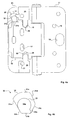
- the door part 20 of the hinge shown in figure 5a is comprised of bent sheet metal 21 and an eccentric device 30.
- the metal sheet 21 includes a flat base part 23, an insert stop 24 that protects at right angles from the base part, and two support parts 25 which are raised from the base part and disposed parallel therewith.
- the base part includes central through-penetrating access holes 26 whose positions coincide with the positions of the mounting holes 17 in the tongue of the frame part, so as to provide access to the mounting screws received by the mounting holes 17 in the tongue on the frame part of the hinge. There are used to this end screws (not shown) whose heads are accommodated in the counter sinks of respective mounting holes 17, said screws being screwed into the door so as to fixate the position of the tongue subsequent to having adjusted the position of the door.
- mounting holes 17 are elongated in a direction parallel with the hinge axle so as to enable adjustment of the height position of the door part of the hinge relative to the tongue 12 on the frame part.
- the base part and support surfaces 25 of the door part 21 of the hinge include further mounting holes 27 for screwing the door part 21 to the door.
- Insert lugs 28 extend towards one another from each of the support parts 25.
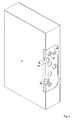
- the sides of the support parts 25 and the insert lugs 28 facing away from the base part 23 are spaced from the base part 23 by a distance which corresponds to the depth of an opening 40 (see figure 3 ) made in the side of the door D that faces towards the frame.
- the distance between the base part 23 and the mutually facing sides of the lugs 28 is such as to enable the tongue 12 of the frame part to be accommodated therebetween.
- the eccentric device is described below with reference to figures 1 , 4a , 4b and 5a .
- the eccentric device 30 includes an eccentric part 31, with a first pin or peg 32 (See figure 1 ) and a second pin or peg 33.
- the two pegs 32, 33 project out axially on each side of the eccentric part.
- the eccentric part also includes a number of eccentrically disposed planar casing surface 31a-31e.
- the planar surface 31a is located at a smallest distance from the rotational axle of the eccentric device, said axle extending axially and centrally through the two pegs 32, 33.
- the casing surface 31 e is located at a largest distance from the rotational axle. In the illustrated case, respective casing surfaces are disposed at a larger distance by 1mm from the rotational axle than the preceding casing surface starting from the innermost casing surface 31a and ending with the outermost casing surface 31e.
- the first peg 32 is rotatably mounted in a through-penetrating hole 29 in the base part 23 intended for this purpose (see figure 1 ).
- the free end of the second peg 33 of the eccentric device includes a planar support surface 33a which is disposed parallel with and in the same plane as the sides of the support parts 25 and the insert lugs 28 that face away from the base part 23.
- the eccentric device 30 is also supported against the bottom of the opening 40 through the planar surface 33b of the second peg 33 when the door part of the hinge is fitted to the door.
- the second peg 33 also includes two radial abutment surfaces 33b, 33c.
- the upper support part 25 includes a fastening lug 35.
- the fastening lug 35 extends on a level with the side of the support part that faces away from the base part 23 generally in a direction towards the eccentric device 30.
- the free end of the fastening lug is disposed at a distance from the rotational axle of the eccentric device so that the first peg 32 of the eccentric device 30 can be moved axially into the hole 29 in the base part 23 without being impeded by the fastening lug 35 when the casing segment 31a located at said smallest distance from the axis of the eccentric device 30 is turned in a direction towards the fastening lug 35.
- the eccentric device When the eccentric device is placed on the base part 23 in this way and the first peg 32 is placed in the hole 29, the eccentric device can be turned so that the part of the eccentric part 31 which lies radially inwards of the casing segments 31b-e located at a greater distance from the axis of the eccentric device is accommodated between the base part 23 and the fastening lug 35.
- the distance between the mutually facing sides of the base part 23 and the fastening lug 35 is adapted to conform to the axial thickness of the eccentric part 31, so that the eccentric part 31 will be held secured between the fastening lug 35 and the base part 23 with a certain degree of bias.
- This bias is not sufficiently great to prevent the eccentric device 30 from being easily rotated with the aid of a screw driver for instance inserted in a groove 32a provided in the free end of the first peg 32.
- the door part 20 of the hinge can be readily manufactured in a cost saving fashion. There is first punched from a steel sheet or some corresponding material a blank whose contours and hole-configuration correspond to the finish bent plate 21. The insert stop 24 of the door part of the hinge is then bent together with support parts 25 with the insert lugs 28 and the fastening lug 35 to the shape illustrated in the figures. The eccentric device 30 cut from a steel blank can then be readily fitted, as described above. When fitting the eccentric device 30, the device will be held securely in place on the door part 20 of the hinge during transportation, storage and mounting of the door part on a door, owing to the bias exerted by the fastening lug.
- the frame art 10 of the hinge is fitted to the frame with the aid of mounting screws inserted through the mounting holes 15 on the frame part of the hinge.
- the door part 20 of the hinge is fitted to the door by first placing said door part in a hole 40 in the door so that the supportive parts 25, the insert lugs 28 and the supportive surface 33a on the second peg 33 of the eccentric device 30 will be supported by the bottom surface of the hole.
- the door part of the hinge is then fastened to the door by screwing mounting screws in counter-sunk holes in the base part 21, said screws being accommodated in mounting holes 27 in the door part of the hinge.
- the respective frame part and door part of the hinge can either be mounted at the place where the door shall be fitted or in a factory.
- One advantage afforded by the inventive hinge is that fitting of the hinge components can be completed in a factory and the door and the frame then transported separately to their place of assembly, where the door can be readily hung on the frame. This avoids the requirement of storing, transporting or fitting loose hinge components.
- the door part 20 of the hinge When the door is to be fitted to the frame, the door part 20 of the hinge is presented to the frame part such that the tongue 12 on the frame part will be accommodated between the base part 23 and the insert lugs 28.
- the free end of the tongue When the tongue 12 on the frame part of the hinge is fully inserted the free end of the tongue will abut the insert stop 24.
- the eccentric device 30 is normally positioned in the factory so that the next innermost casing surface 31b will abut the upper side of the tongue 12 on the frame part, as shown in figure 4a .
- the door is held temporarily in place in this state by virtue of the weight of the door and the friction between the eccentric device 30 and the tongue 12 of the frame part, therewith enabling height and lateral adjustments to be made.
- a height adjustment can be made, for instance, by inserting the blade of a a screwdriver in the groove 32a on the first peg 32 of the eccentric device 30 and rotating said device.
- the eccentric device When the eccentric device is rotated one step in a counter clockwise direction from the position shown in figure 4 (clockwise in figure 1 ) the innermost casing surface 31 a will lie against the tongue 12 of the frame part, causing the door to be lowered by 1 mm.
- the eccentric device 30 is instead rotated clockwise from the position shown in figure 4a (counter clockwise in figure 1 ) the door will be raised stepwise by 1 mm in each step as the casing surfaces 31 c, 31 d and 31e sequentially come into abutment with the tongue 12 of the frame part.
- a height adjustment of -1 to +3 mm can be achieved from the normal position shown in figure 4a .
- the eccentric device 30 When the eccentric device has been rotated to a maximum height position in which the casing surface 31e lies against the tongue 12 of the frame part, the first abutment 33b of the second peg 33 will lie in abutment with the free end of the fastening lug 35.
- the eccentric device 30 is therewith prevented from being rotated from the highest setting to the lowest setting directly, such direct movement otherwise causing damage to the hinge, to the door and injury to people located in the vicinity of the door.
- the second abutment 33c of the second peg 33 forms in co-action with the fastening lug 35 a corresponding rotation stopping means which prevents the eccentric device from being rotated directly from the lowermost setting to the highest setting.
- Lateral adjustment to the door is achieved by turning the setting screws 18, whose free ends support against the insert lugs 28, until the base part 23 of the door-part of the hinge is at a desired angle relative to the tongue 12 of the frame part of the hinge.
- an aperture that corresponds to the shape of the insert lugs 28 can be made in the tongue 12 of the frame part around the mouth of the threaded holes that receive the lateral adjustment screws 18, in order to obtain a greater lateral adjustment range.
- the tongue 12 of the frame part of the hinge is secured to the door D, by inserting mounting screws in through the access holes 26 and fastening the screws in the door such that the heads of the screws will lie against and be accommodated in the counter sinks of the mounting holes 17 in the tongue 12 of the frame part. This will result in further fixation of the door part 20 to the door, since the lateral adjustment screws press the insert lugs 28, and therewith the door part 20, against the bottom of the aperture 40.
- the eccentric device may comprise a continuous eccentric casing surface instead of comprising a number of planar casing surfaces.
- a height adjustment marking may be provided on the first peg 32 of the eccentric device so as to indicate a set position. If desired, this marking can be supplemented with corresponding position markings on the visible side of the door part 20 of the hinge, around the hole 29. These markings may conveniently show the relative height positions for the abutment of different casing surfaces with the tongue of the frame part of the hinge, i.e. -1,0,+1,+2,+3 for instance.
Landscapes
- Engineering & Computer Science (AREA)
- Mechanical Engineering (AREA)
- Hinges (AREA)
Claims (6)
- Ein Scharnier, umfassend ein Rahmenteil (10), welches dafür gedacht ist, an einem Rahmen oder Ähnlichem befestigt zu sein, und ein Türteil (20), welches dafür gedacht ist, an einem Türblatt (D) oder Ähnlichem befestigt zu sein, wobei das Rahmenteil (10) ein Rahmenblatt (11) und eine Zunge (12) aufweist, welche mit dem Rahmenblatt (11) mittels einer Scharnierachse verbunden ist, und wobei das Türteil (20) des Scharniers ein gebogenes oder gefaltetes Metallblatt (21) umfasst, welches geformt ist, um die Zunge (12) auf dem Rahmenteil (10) aufzunehmen und eine exzentrische Vorrichtung (30) für die Höheneinstellung des Türteils (20) relativ zu der Zunge (12) des Rahmenteils (10), wobei die exzentrische Vorrichtung (30) ein exzentrisches Teil (31) und einen ersten Stift (32) aufweist, welcher axial aus dem exzentrischen Teil (31) hervorsteht und welcher in einer durchgehenden Öffnung (29) in einem Basisteil (23) des gebogenen oder gefalteten Metallblatts (21) aufgenommen ist, dadurch gekennzeichnet, dass das gebogene Metallblatt (21) einen ersten Zapfen (35) aufweist, welcher einstückig mit dem gebogenen oder gefalteten Metallblatt (21) und seinem Basisteil (23) gebildet ist, und welcher angeordnet ist, um an die Seite des exzentrischen Teils (31) gegenüber dem ersten Stift (32) anzugrenzen, um den ersten Stift (32) am Austreten durch die Öffnung (29) zu hindern.
- Scharnier nach Anspruch 1, wobei die exzentrische Vorrichtung (30) einen zweiten Stift (33) aufweist, welcher axial von der Seite des exzentrischen Teils (31) gegenüber dem ersten Stift (32) hervorsteht, und welcher eine Grenzoberfläche (33) aufweist, welche eine Endposition zur Rotation der exzentrischen Vorrichtung (30) definiert, wenn sie an den ersten Ansatz (35) angrenzt.
- Scharnier nach Anspruch 1 oder 2, wobei das exzentrische Teil (31) eine Anzahl exzentrisch angeordneter flacher Gehäusesegmente (31a, 31b, 31c, 31d, 31e) zum Angrenzen an die Zunge (12) des Rahmenteils (10) aufweist.
- Scharnier nach Anspruch 3, wobei zumindest eines der Gehäusesegmente (31a) mit einem Abstand von der Achse der exzentrischen Vorrichtung (30) so angeordnet ist, dass in Relation zu der Länge des ersten Ansatzes (35) der erste Stift (32) der exzentrischen Vorrichtung (30) in die durchgehende Öffnung (29) eingefügt werden kann und danach so rotiert wird, dass das exzentrische Teil (31) zwischen dem ersten Ansatz (35) und dem Basisteil (23) des gebogenen Metallblatts (21) aufgenommen werden wird.
- Scharnier nach irgendeinem der Ansprüche 1 - 3, wobei das gebogene Metallblatt (21) zumindest einen zweiten Ansatz (28) aufweist, welcher einstückig mit dem gebogenen oder gefalteten Metallblatt (21) und seinem Basisteil (23) gebildet ist, und welcher die Zunge (12) des Rahmenteils (10) zwischen sich selbst und dem Basisteil (23) aufnimmt, und einen Stop für eine Einstellungsschraube (18) bildet, die in die Zunge (12) des Rahmenteils (10) geschraubt ist, um eine laterale Einstellung der Tür zu ermöglichen.
- Scharnier nach Anspruch 5, wobei das gebogene Metallblatt (21) zwei sich gegenüberliegende zweite Ansätze (18) aufweist.
Applications Claiming Priority (1)
| Application Number | Priority Date | Filing Date | Title |
|---|---|---|---|
| SE0501361A SE529137C2 (sv) | 2005-06-15 | 2005-06-15 | Insticksgångjärn |
Publications (3)
| Publication Number | Publication Date |
|---|---|
| EP1734211A2 EP1734211A2 (de) | 2006-12-20 |
| EP1734211A3 EP1734211A3 (de) | 2010-06-02 |
| EP1734211B1 true EP1734211B1 (de) | 2012-01-04 |
Family
ID=37012037
Family Applications (1)
| Application Number | Title | Priority Date | Filing Date |
|---|---|---|---|
| EP06445044A Not-in-force EP1734211B1 (de) | 2005-06-15 | 2006-06-14 | Scharnier |
Country Status (3)
| Country | Link |
|---|---|
| EP (1) | EP1734211B1 (de) |
| AT (1) | ATE540184T1 (de) |
| SE (1) | SE529137C2 (de) |
Families Citing this family (3)
| Publication number | Priority date | Publication date | Assignee | Title |
|---|---|---|---|---|
| DE102007043757B3 (de) | 2007-09-13 | 2008-11-20 | Schüring GmbH & Co. Fenster-Technologie KG | Verstellbares Flügelbandteil eines Gelenkbandes |
| DE102010012576B3 (de) * | 2010-03-23 | 2011-03-10 | Simonswerk, Gesellschaft mit beschränkter Haftung | Türband, insbesondere für gefälzte Gebäudeabschlusstüren aus Holz |
| CN110230448B (zh) * | 2019-07-17 | 2024-01-26 | 永康市桂锦工贸有限公司 | 一种三维可调合页 |
Family Cites Families (3)
| Publication number | Priority date | Publication date | Assignee | Title |
|---|---|---|---|---|
| US5799370A (en) * | 1996-06-12 | 1998-09-01 | The Stanley Works | Adjustable hinge |
| GB2377729B (en) * | 1998-05-13 | 2003-03-05 | Frip Ab | Hinge device of the snap-in type |
| SE516251C2 (sv) * | 2000-04-28 | 2001-12-10 | Assa Ab | För upptagning av insnäppbart gångledblad avsedd hållardosa till gångled |
-
2005
- 2005-06-15 SE SE0501361A patent/SE529137C2/sv not_active IP Right Cessation
-
2006
- 2006-06-14 EP EP06445044A patent/EP1734211B1/de not_active Not-in-force
- 2006-06-14 AT AT06445044T patent/ATE540184T1/de active
Also Published As
| Publication number | Publication date |
|---|---|
| EP1734211A3 (de) | 2010-06-02 |
| ATE540184T1 (de) | 2012-01-15 |
| SE0501361L (sv) | 2006-12-16 |
| SE529137C2 (sv) | 2007-05-08 |
| EP1734211A2 (de) | 2006-12-20 |
Similar Documents
| Publication | Publication Date | Title |
|---|---|---|
| US5713105A (en) | Adjustable hinge | |
| US5058236A (en) | Adjustable hinge | |
| US5946952A (en) | Lock cover system | |
| AU769885B2 (en) | Hinge for an opening door or window frame | |
| US6826870B2 (en) | Adjustable automatic positioning hinge for a glass door | |
| EP1672155A1 (de) | Verstellbares Scharnier für Türen und Fenster | |
| EP2182151B1 (de) | Verstellscharnier | |
| NZ533155A (en) | An adjustable hanger hinge | |
| JP6917052B2 (ja) | スライドヒンジ及びこれを用いたキャビネット | |
| US5412840A (en) | Adjustable, furniture hinge having support arm with extensions engaging grooves in mounting plate | |
| US8863358B2 (en) | Adjustable hinge | |
| US7694388B2 (en) | Adjustable hinge | |
| EP1734211B1 (de) | Scharnier | |
| US10596975B1 (en) | Mounting system with pivot locking features | |
| US7490385B2 (en) | Hinge base with position adjustment | |
| EP1455042B1 (de) | Verstellbares Scharnier für Fenster oder Türen | |
| US6901633B2 (en) | Door hinge | |
| GB2069592A (en) | An adjustable door hinge | |
| US5095583A (en) | Folding-arm bearing for an oscillating-swinging leaf | |
| EP2597237B1 (de) | Scharnierhalter | |
| US20010020317A1 (en) | Hinge, and method for height adjustment of a hinge | |
| US9856693B2 (en) | Corner fitting with variably adjustable restraining area | |
| US7703178B2 (en) | Hinge | |
| EP0735222A1 (de) | Scharnier | |
| CN1097667C (zh) | 固定门扇的配件 |
Legal Events
| Date | Code | Title | Description |
|---|---|---|---|
| PUAI | Public reference made under article 153(3) epc to a published international application that has entered the european phase |
Free format text: ORIGINAL CODE: 0009012 |
|
| AK | Designated contracting states |
Kind code of ref document: A2 Designated state(s): AT BE BG CH CY CZ DE DK EE ES FI FR GB GR HU IE IS IT LI LT LU LV MC NL PL PT RO SE SI SK TR |
|
| AX | Request for extension of the european patent |
Extension state: AL BA HR MK YU |
|
| PUAL | Search report despatched |
Free format text: ORIGINAL CODE: 0009013 |
|
| AK | Designated contracting states |
Kind code of ref document: A3 Designated state(s): AT BE BG CH CY CZ DE DK EE ES FI FR GB GR HU IE IS IT LI LT LU LV MC NL PL PT RO SE SI SK TR |
|
| AX | Request for extension of the european patent |
Extension state: AL BA HR MK RS |
|
| 17P | Request for examination filed |
Effective date: 20101201 |
|
| AKX | Designation fees paid |
Designated state(s): AT BE BG CH CY CZ DE DK EE ES FI FR GB GR HU IE IS IT LI LT LU LV MC NL PL PT RO SE SI SK TR |
|
| GRAP | Despatch of communication of intention to grant a patent |
Free format text: ORIGINAL CODE: EPIDOSNIGR1 |
|
| RIC1 | Information provided on ipc code assigned before grant |
Ipc: E05D 7/04 20060101AFI20110601BHEP |
|
| GRAS | Grant fee paid |
Free format text: ORIGINAL CODE: EPIDOSNIGR3 |
|
| GRAA | (expected) grant |
Free format text: ORIGINAL CODE: 0009210 |
|
| AK | Designated contracting states |
Kind code of ref document: B1 Designated state(s): AT BE BG CH CY CZ DE DK EE ES FI FR GB GR HU IE IS IT LI LT LU LV MC NL PL PT RO SE SI SK TR |
|
| REG | Reference to a national code |
Ref country code: GB Ref legal event code: FG4D |
|
| REG | Reference to a national code |
Ref country code: CH Ref legal event code: EP |
|
| REG | Reference to a national code |
Ref country code: AT Ref legal event code: REF Ref document number: 540184 Country of ref document: AT Kind code of ref document: T Effective date: 20120115 |
|
| REG | Reference to a national code |
Ref country code: IE Ref legal event code: FG4D |
|
| REG | Reference to a national code |
Ref country code: DE Ref legal event code: R096 Ref document number: 602006026800 Country of ref document: DE Effective date: 20120301 |
|
| REG | Reference to a national code |
Ref country code: NL Ref legal event code: VDEP Effective date: 20120104 |
|
| PG25 | Lapsed in a contracting state [announced via postgrant information from national office to epo] |
Ref country code: SI Free format text: LAPSE BECAUSE OF FAILURE TO SUBMIT A TRANSLATION OF THE DESCRIPTION OR TO PAY THE FEE WITHIN THE PRESCRIBED TIME-LIMIT Effective date: 20120104 |
|
| LTIE | Lt: invalidation of european patent or patent extension |
Effective date: 20120104 |
|
| PG25 | Lapsed in a contracting state [announced via postgrant information from national office to epo] |
Ref country code: IS Free format text: LAPSE BECAUSE OF FAILURE TO SUBMIT A TRANSLATION OF THE DESCRIPTION OR TO PAY THE FEE WITHIN THE PRESCRIBED TIME-LIMIT Effective date: 20120504 Ref country code: LT Free format text: LAPSE BECAUSE OF FAILURE TO SUBMIT A TRANSLATION OF THE DESCRIPTION OR TO PAY THE FEE WITHIN THE PRESCRIBED TIME-LIMIT Effective date: 20120104 Ref country code: NL Free format text: LAPSE BECAUSE OF FAILURE TO SUBMIT A TRANSLATION OF THE DESCRIPTION OR TO PAY THE FEE WITHIN THE PRESCRIBED TIME-LIMIT Effective date: 20120104 Ref country code: BE Free format text: LAPSE BECAUSE OF FAILURE TO SUBMIT A TRANSLATION OF THE DESCRIPTION OR TO PAY THE FEE WITHIN THE PRESCRIBED TIME-LIMIT Effective date: 20120104 Ref country code: BG Free format text: LAPSE BECAUSE OF FAILURE TO SUBMIT A TRANSLATION OF THE DESCRIPTION OR TO PAY THE FEE WITHIN THE PRESCRIBED TIME-LIMIT Effective date: 20120404 |
|
| PG25 | Lapsed in a contracting state [announced via postgrant information from national office to epo] |
Ref country code: FI Free format text: LAPSE BECAUSE OF FAILURE TO SUBMIT A TRANSLATION OF THE DESCRIPTION OR TO PAY THE FEE WITHIN THE PRESCRIBED TIME-LIMIT Effective date: 20120104 Ref country code: PL Free format text: LAPSE BECAUSE OF FAILURE TO SUBMIT A TRANSLATION OF THE DESCRIPTION OR TO PAY THE FEE WITHIN THE PRESCRIBED TIME-LIMIT Effective date: 20120104 Ref country code: GR Free format text: LAPSE BECAUSE OF FAILURE TO SUBMIT A TRANSLATION OF THE DESCRIPTION OR TO PAY THE FEE WITHIN THE PRESCRIBED TIME-LIMIT Effective date: 20120405 Ref country code: LV Free format text: LAPSE BECAUSE OF FAILURE TO SUBMIT A TRANSLATION OF THE DESCRIPTION OR TO PAY THE FEE WITHIN THE PRESCRIBED TIME-LIMIT Effective date: 20120104 Ref country code: PT Free format text: LAPSE BECAUSE OF FAILURE TO SUBMIT A TRANSLATION OF THE DESCRIPTION OR TO PAY THE FEE WITHIN THE PRESCRIBED TIME-LIMIT Effective date: 20120504 |
|
| REG | Reference to a national code |
Ref country code: AT Ref legal event code: MK05 Ref document number: 540184 Country of ref document: AT Kind code of ref document: T Effective date: 20120104 |
|
| PG25 | Lapsed in a contracting state [announced via postgrant information from national office to epo] |
Ref country code: CY Free format text: LAPSE BECAUSE OF FAILURE TO SUBMIT A TRANSLATION OF THE DESCRIPTION OR TO PAY THE FEE WITHIN THE PRESCRIBED TIME-LIMIT Effective date: 20120104 |
|
| PG25 | Lapsed in a contracting state [announced via postgrant information from national office to epo] |
Ref country code: SE Free format text: LAPSE BECAUSE OF FAILURE TO SUBMIT A TRANSLATION OF THE DESCRIPTION OR TO PAY THE FEE WITHIN THE PRESCRIBED TIME-LIMIT Effective date: 20120104 Ref country code: DK Free format text: LAPSE BECAUSE OF FAILURE TO SUBMIT A TRANSLATION OF THE DESCRIPTION OR TO PAY THE FEE WITHIN THE PRESCRIBED TIME-LIMIT Effective date: 20120104 Ref country code: CZ Free format text: LAPSE BECAUSE OF FAILURE TO SUBMIT A TRANSLATION OF THE DESCRIPTION OR TO PAY THE FEE WITHIN THE PRESCRIBED TIME-LIMIT Effective date: 20120104 Ref country code: RO Free format text: LAPSE BECAUSE OF FAILURE TO SUBMIT A TRANSLATION OF THE DESCRIPTION OR TO PAY THE FEE WITHIN THE PRESCRIBED TIME-LIMIT Effective date: 20120104 Ref country code: EE Free format text: LAPSE BECAUSE OF FAILURE TO SUBMIT A TRANSLATION OF THE DESCRIPTION OR TO PAY THE FEE WITHIN THE PRESCRIBED TIME-LIMIT Effective date: 20120104 |
|
| PLBE | No opposition filed within time limit |
Free format text: ORIGINAL CODE: 0009261 |
|
| STAA | Information on the status of an ep patent application or granted ep patent |
Free format text: STATUS: NO OPPOSITION FILED WITHIN TIME LIMIT |
|
| PG25 | Lapsed in a contracting state [announced via postgrant information from national office to epo] |
Ref country code: IT Free format text: LAPSE BECAUSE OF FAILURE TO SUBMIT A TRANSLATION OF THE DESCRIPTION OR TO PAY THE FEE WITHIN THE PRESCRIBED TIME-LIMIT Effective date: 20120104 Ref country code: SK Free format text: LAPSE BECAUSE OF FAILURE TO SUBMIT A TRANSLATION OF THE DESCRIPTION OR TO PAY THE FEE WITHIN THE PRESCRIBED TIME-LIMIT Effective date: 20120104 |
|
| 26N | No opposition filed |
Effective date: 20121005 |
|
| PG25 | Lapsed in a contracting state [announced via postgrant information from national office to epo] |
Ref country code: AT Free format text: LAPSE BECAUSE OF FAILURE TO SUBMIT A TRANSLATION OF THE DESCRIPTION OR TO PAY THE FEE WITHIN THE PRESCRIBED TIME-LIMIT Effective date: 20120104 Ref country code: MC Free format text: LAPSE BECAUSE OF NON-PAYMENT OF DUE FEES Effective date: 20120630 |
|
| REG | Reference to a national code |
Ref country code: DE Ref legal event code: R097 Ref document number: 602006026800 Country of ref document: DE Effective date: 20121005 Ref country code: CH Ref legal event code: PL |
|
| REG | Reference to a national code |
Ref country code: CH Ref legal event code: PL |
|
| GBPC | Gb: european patent ceased through non-payment of renewal fee |
Effective date: 20120614 |
|
| REG | Reference to a national code |
Ref country code: IE Ref legal event code: MM4A |
|
| REG | Reference to a national code |
Ref country code: FR Ref legal event code: ST Effective date: 20130228 |
|
| REG | Reference to a national code |
Ref country code: DE Ref legal event code: R119 Ref document number: 602006026800 Country of ref document: DE Effective date: 20130101 |
|
| PG25 | Lapsed in a contracting state [announced via postgrant information from national office to epo] |
Ref country code: FR Free format text: LAPSE BECAUSE OF NON-PAYMENT OF DUE FEES Effective date: 20120702 Ref country code: DE Free format text: LAPSE BECAUSE OF NON-PAYMENT OF DUE FEES Effective date: 20130101 Ref country code: GB Free format text: LAPSE BECAUSE OF NON-PAYMENT OF DUE FEES Effective date: 20120614 Ref country code: LI Free format text: LAPSE BECAUSE OF NON-PAYMENT OF DUE FEES Effective date: 20120630 Ref country code: IE Free format text: LAPSE BECAUSE OF NON-PAYMENT OF DUE FEES Effective date: 20120614 Ref country code: CH Free format text: LAPSE BECAUSE OF NON-PAYMENT OF DUE FEES Effective date: 20120630 Ref country code: ES Free format text: LAPSE BECAUSE OF FAILURE TO SUBMIT A TRANSLATION OF THE DESCRIPTION OR TO PAY THE FEE WITHIN THE PRESCRIBED TIME-LIMIT Effective date: 20120415 |
|
| PG25 | Lapsed in a contracting state [announced via postgrant information from national office to epo] |
Ref country code: TR Free format text: LAPSE BECAUSE OF FAILURE TO SUBMIT A TRANSLATION OF THE DESCRIPTION OR TO PAY THE FEE WITHIN THE PRESCRIBED TIME-LIMIT Effective date: 20120104 |
|
| PG25 | Lapsed in a contracting state [announced via postgrant information from national office to epo] |
Ref country code: LU Free format text: LAPSE BECAUSE OF NON-PAYMENT OF DUE FEES Effective date: 20120614 |
|
| PG25 | Lapsed in a contracting state [announced via postgrant information from national office to epo] |
Ref country code: HU Free format text: LAPSE BECAUSE OF FAILURE TO SUBMIT A TRANSLATION OF THE DESCRIPTION OR TO PAY THE FEE WITHIN THE PRESCRIBED TIME-LIMIT Effective date: 20060614 |