EP1732775B1 - Fahrzeugdach mit solarzellen und einer vorrichtung zur belüftung und kühlung eines kraftfahrzeuginnenraumes - Google Patents
Fahrzeugdach mit solarzellen und einer vorrichtung zur belüftung und kühlung eines kraftfahrzeuginnenraumes Download PDFInfo
- Publication number
- EP1732775B1 EP1732775B1 EP05715790A EP05715790A EP1732775B1 EP 1732775 B1 EP1732775 B1 EP 1732775B1 EP 05715790 A EP05715790 A EP 05715790A EP 05715790 A EP05715790 A EP 05715790A EP 1732775 B1 EP1732775 B1 EP 1732775B1
- Authority
- EP
- European Patent Office
- Prior art keywords
- vehicle
- roof
- air
- vehicle roof
- cooling
- Prior art date
- Legal status (The legal status is an assumption and is not a legal conclusion. Google has not performed a legal analysis and makes no representation as to the accuracy of the status listed.)
- Expired - Lifetime
Links
Images

Classifications
-
- B—PERFORMING OPERATIONS; TRANSPORTING
- B60—VEHICLES IN GENERAL
- B60H—ARRANGEMENTS OF HEATING, COOLING, VENTILATING OR OTHER AIR-TREATING DEVICES SPECIALLY ADAPTED FOR PASSENGER OR GOODS SPACES OF VEHICLES
- B60H1/00—Heating, cooling or ventilating devices
- B60H1/24—Ventilating devices where the heating or cooling is irrelevant
- B60H1/26—Ventilating openings in vehicle exterior; Ducts for conveying ventilating air
- B60H1/262—Openings in or on the vehicle roof
-
- B—PERFORMING OPERATIONS; TRANSPORTING
- B60—VEHICLES IN GENERAL
- B60H—ARRANGEMENTS OF HEATING, COOLING, VENTILATING OR OTHER AIR-TREATING DEVICES SPECIALLY ADAPTED FOR PASSENGER OR GOODS SPACES OF VEHICLES
- B60H1/00—Heating, cooling or ventilating devices
- B60H1/00421—Driving arrangements for parts of a vehicle air-conditioning
- B60H1/00428—Driving arrangements for parts of a vehicle air-conditioning electric
-
- Y—GENERAL TAGGING OF NEW TECHNOLOGICAL DEVELOPMENTS; GENERAL TAGGING OF CROSS-SECTIONAL TECHNOLOGIES SPANNING OVER SEVERAL SECTIONS OF THE IPC; TECHNICAL SUBJECTS COVERED BY FORMER USPC CROSS-REFERENCE ART COLLECTIONS [XRACs] AND DIGESTS
- Y02—TECHNOLOGIES OR APPLICATIONS FOR MITIGATION OR ADAPTATION AGAINST CLIMATE CHANGE
- Y02T—CLIMATE CHANGE MITIGATION TECHNOLOGIES RELATED TO TRANSPORTATION
- Y02T10/00—Road transport of goods or passengers
- Y02T10/80—Technologies aiming to reduce greenhouse gasses emissions common to all road transportation technologies
- Y02T10/88—Optimized components or subsystems, e.g. lighting, actively controlled glasses
Definitions
- the invention relates to a vehicle roof with solar cells and a device for ventilating and cooling a motor vehicle interior with rear side disposed in the vehicle roof air inlet openings and at least one associated air duct according to the preamble of claim 1.
- a motor vehicle interior is achieved by blowing outside air surrounding the motor vehicle into the interior of the motor vehicle, wherein the cooling of the heated interior is achieved by the temperature difference between outside and inside temperature and the cooling effect of the air flow.
- Devices for such supply or also removal of air from outside to inside or vice versa are according to DE 40 22 928 C1 also known for the roof area of a motor vehicle. They usually consist of a fan which is arranged in the region of a roof cutout which can be closed by means of a conventional sunroof lid.
- Out DE 39 38 259 C1 is a motor vehicle with a hinged roof cover in the vehicle roof known, wherein upon opening the roof cover forcibly a fan is brought into an operative position in an opening between the roof cover and a vehicle roof opening frame.
- a fan can be operated electrically with a roof-mounted solar module.
- Such an arrangement for aerating the passenger compartment also serves to supply by means of the fan outside air into the interior of the passenger compartment to cool the passenger compartment inside solely by the supplied outside air.
- such an outside air supply can achieve a maximum of 50% cooling of the interior, since the outside air - especially on hot days - due to a strong heating only very limited contributes to the cooling of a heated vehicle compartment.
- the present invention seeks to provide a vehicle roof with a device for ventilating and cooling a motor vehicle interior available, even at high outside temperatures effective cooling of the vehicle interior - preferably in the upper area - allows easy in their construction and cost in their production.
- the core idea of the invention is that in a vehicle roof with solar cells and a device for ventilation and cooling of a motor vehicle interior with rear side arranged in the vehicle air inlet openings and at least one associated air duct this air duct is limited to a rear area of the vehicle roof and inside at least one fan for suction of outside air and at least one cooling element for cooling the sucked air.
- a constructive simplicity is achieved in that the underside of the air duct by a first portion extending in a direction from the vehicle rear to the vehicle front side roof portion and the top of the air duct by a second portion extending in the direction from the vehicle front to the vehicle rear side Roof portion are formed.
- the air duct is limited to the rear area of the vehicle roof and the fan and a cooling element is integrated in this air duct, is on a simple way to obtain a device for ventilation and cooling, which does not reduce the height of the passenger compartment on the one hand and on the other effective cooling of the passenger compartment by means of the cooling element causes.
- a cooling element can preferably be supplied with power by the solar cells, so that even during the state of a switched-off vehicle engine effective cooling of the interior is possible without unnecessarily burdening the vehicle battery.
- the solar cells are mounted in the second section above the air duct on the vehicle roof outside and thereby allow a short electrical connection path between the electricity generating solar cells and the power consuming fan and the power consuming cooling element.
- an air flow generated in the air duct runs substantially in the vehicle longitudinal direction such that outside air is sucked in via the rear-side arranged air inlet openings, this process being assisted by the suction effect in the rear region of the moving vehicle, and via air outlet openings which are on a side facing the vehicle front side of the air duct are blown into the interior.
- the cooling element which may be formed, for example, as a Peltier cooling element in order to achieve an effective cooling of the air flow.
- Such a very simple structure of the device for ventilating and for cooling the passenger compartment also has the simplification features of the formation of the lower and upper side by vehicle roof portions. This eliminates the need for additional components and walls.
- the fan can be designed both as an axial and as a radial fan or any other conceivable type of fan.
- the air inlet openings, the air outlet openings and the air duct can extend over the entire vehicle roof width.
- Such an arrangement also has an optically advantageous effect both on the vehicle exterior and on the vehicle interior.
- such a device can be optically and functionally well integrated in the rear region of a tiltable roof cover or for the additional formation of a spoiler.
- Fig. 1 a section of a vehicle with a device according to an embodiment of the invention is shown in a schematic side view.
- the vehicle has to the vehicle front 1 towards a windshield 2 and the vehicle rear side 3 toward a rear window 4.
- a vehicle roof portion 5a extending from the vehicle front side 1 in the direction of the vehicle rear side 3 can be designed to be tiltable and overlaps in the rear area of the vehicle roof with a vehicle roof portion 5b extending from the vehicle rear side 3 to the vehicle front side 1.
- Solar cells 6 are arranged above an air duct 7, which extends between air inlet openings 8 arranged on the rear side and air outlet openings 9 facing the vehicle front side 1.
- the air flow determined by the air inlet and outlet openings is represented by arrows 10, 11.
- a first portion 12 of the roof portion 5b is located as a bottom of the air duct 7 below a second portion 13 of the roof portion 5a, which also forms the top of the Lwill beskanals.
- a cooling element 14 for cooling the air flow flowing through 10, 11 and a fan 15 for sucking the outside air is disposed in the air duct.
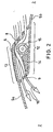
- FIG. 2 is a schematic representation of a portion of the vehicle roof shown in Fig. 1 reproduced in an enlarged view.
- An air flow 16 shown in this drawing clearly shows that the fan 15 draws in the outside air via the air inlet opening 8 and forcibly leads past the cooling element 14 due to its rotational movement. In this way, the air flow is reliably and effectively brought to a desired cooling temperature, depending on which cooling temperature has been set, the cooling element. In this way, even an air conditioning of the passenger compartment, ie the achievement of an interior temperature that is below the outside temperature, possible.
Landscapes
- Physics & Mathematics (AREA)
- Thermal Sciences (AREA)
- Engineering & Computer Science (AREA)
- Mechanical Engineering (AREA)
- Air-Conditioning For Vehicles (AREA)
- Arrangement Or Mounting Of Propulsion Units For Vehicles (AREA)
- Photovoltaic Devices (AREA)
- Body Structure For Vehicles (AREA)
- Cooling, Air Intake And Gas Exhaust, And Fuel Tank Arrangements In Propulsion Units (AREA)
Description
- Die Erfindung betrifft ein Fahrzeugdach mit Solarzellen und einer Vorrichtung zur Belüftung und Kühlung eines Kraftfahrzeuginnenraumes mit im Fahrzeugdach heckseitig angeordneten Lufteinlassöffnungen und mindestens einem damit verbundenen Luftführungskanal gemäß dem Obergriff des Patentanspruches 1.
- Herkömmlicherweise wird ein Kraftfahrzeugsinnenraum durch Einblasen von das Kraftfahrzeug umgebende Außenluft in das Innere des Kraftfahrzeuges erreicht, wobei die Kühlung des aufgeheizten Innenraumes durch den Temperaturunterschied zwischen Außen- und Innentemperatur sowie die kühlende Wirkung der Luftströmung erzielt wird. Vorrichtungen für ein derartiges Zu- oder auch Abführen von Luft von außen nach innen beziehungsweise vice versa sind gemäß
DE 40 22 928 C1 auch für den Dachbereich eines Kraftfahrzeuges bekannt. Sie bestehen in der Regel aus einem Ventilator, der im Bereich eines Dachauschnitts, welcher mittels eines herkömmlichen Schiebedachdeckels verschließbar ist, angeordnet ist. - Aus
DE 39 38 259 C1 ist ein Kraftfahrzeug mit einem klappbaren Dachdeckel im Fahrzeugdach bekannt, wobei bei einem Aufklappen des Dachdeckels zwangsweise einen Lüfter in eine wirksame Stellung in einer Öffnung zwischen dem Dachdeckel und einem Fahrzeugdachöffnungsrahmen gebracht wird. Ein derartiger Lüfter kann mit einem dachseitig angebrachten Solarmodul elektrisch betrieben werden. Eine derartige Anordnung zum Belüften der Fahrgastzelle dient ebenso dazu, mittels des Lüfters Außenluft in das Innere der Fahrgastzelle zuzuführen, um das Fahrgastzelleninnere allein durch die zugeführte Außenluft zu kühlen. Eine derartige Außenluftstromzufuhr kann jedoch maximal eine 50 %ige Abkühlung des Innenraums erzielen, da die Außenluft - insbesondere an heißen Tagen - aufgrund einer starken Erwärmung nur sehr begrenzt zur Abkühlung eines aufgeheizten Fahrzeugraumes beiträgt. - Insbesondere bei der Verwendung von Glasdächern, die gegebenenfalls mit Solarzellen bestückt sind, findet eine stärkere Aufheizung des Fahrgastinnenraumes unmittelbar unterhalb des Glasdaches, also im oberen Bereich des Fahrgastinnenraumes, statt. Somit ist es wünschenswert, Außenluft vorrangig in diesem oberen Fahrgastinnenraumbereich einzublasen. Aus
DE 42 04 785 A1 ist eine Anordnung zur Klimatisierung eines Fahrzeuginnenraumes bekannt, die zusätzlich einen an der unteren Innenseite des Fahrzeugdaches sich über die gesamte Länge des Fahrzeugdaches hinwegstreckenden Wärmetauscher aufweist, um die in eine Kassette, in welcher der Wärmetauscher angeordnet ist, eingeblasene Außenluft dazu zu nutzen, zusätzlich gekühlte Luft dem Fahrgastinnenraum zuzuführen. Derartige Wärmetauscher sind begrenzt in ihrer Abkühlungsfähigkeit in Abhängigkeit von der Temperatur der Außenluft. Zudem erfordern derartige Wärmetauscher die dachseitig angeordneten Kassetten, welche eine Reduzierung der Höhe des Fahrgastinnenraumes zur Folge haben. Weiterhin sind derartige Wärmetauscher in Kombination mit den Kassetten aufwendig in ihrer Konstruktion und kostenintensiv in ihrer Herstellung. - Demzufolge liegt der vorliegenden Erfindung die Aufgabe zugrunde, ein Fahrzeugdach mit einer Vorrichtung zur Belüftung und Kühlung eines Kraftfahrzeuginnenraumes zur Verfügung zu stellen, der auch bei hohen Außentemperaturen eine wirksame Abkühlung des Fahrzeuginnenraumes - vorzugsweise in dessen oberen Bereich - zulässt, einfach in ihrem Aufbau und kostengünstig in ihrer Herstellung ist.
- Diese Aufgabe wird gemäß den Merkmalen des Patentanspruches 1 gelöst.
- Kerngedanke der Erfindung ist es, dass bei einem Fahrzeugdach mit Solarzellen und einer Vorrichtung zur Belüftung und Kühlung eines Kraftfahrzeuginnenraumes mit im Fahrzeugdach heckseitig angeordneten Lufteinlassöffnungen und mindestens einem damit verbundenen Luftführungskanal dieser Luftführungskanal auf einen heckseitigen Bereich des Fahrzeugdaches begrenzt ist und innenseitig mindestens einen Lüfter zum Ansaugen von Außenluft und mindestens ein Kühlelement zum Kühlen der angesaugten Luft aufweist. Eine konstruktive Einfachheit wird dadurch erreicht, dass die Unterseite des Luftführungskanals durch einen ersten Abschnitt eines sich in Richtung von der Fahrzeugheck- zur Fahrzeugvorderseite hin erstreckenden Dachanteils und die Oberseite des Luftführungskanals durch einen zweiten Abschnitt eines sich in Richtung von der Fahrzeugvorder- zur Fahrzeugheckseite hin erstreckenden Dachanteils gebildet sind.
- Da der Luftführungskanal auf den heckseitigen Bereich des Fahrzeugdaches begrenzt ist und der Lüfter sowie ein Kühlelement in diesen Luftführungskanal integriert ist, wird auf einfache Weise eine Vorrichtung zur Belüftung und Kühlung erhalten, die zum Einen dem Fahrgastinnenraum nicht in seiner Höhe reduziert und zum Anderen eine effektive Kühlung des Fahrgastinnenraumes mittels des Kühlelementes bewirkt. Ein derartiges Kühlelement kann vorzugsweise durch die Solarzellen mit Strom versorgt werden, sodass auch während des Zustands eines abgeschalteten Fahrzeugmotors eine effektive Kühlung des Innenraumes möglich ist, ohne hierzu die Fahrzeugbatterie unnötig zu belasten.
- Die Solarzellen sind in dem zweiten Abschnitt oberhalb des Luftführungskanals fahrzeugdachaußenseitig angebracht und ermöglichen dadurch einen kurzen elektrischen Verbindungsweg zwischen den stromerzeugenden Solarzellen und den stromverbrauchenden Lüfter sowie dem stromverbrauchenden Kühlelement.
- Vorzugsweise verläuft ein in dem Luftführungskanal erzeugter Luftstrom im Wesentlichen in Fahrzeuglängsrichtung derart, dass über die heckseitige angeordneten Lufteinlassöffnungen Außenluft angesaugt wird, wobei dieser Vorgang durch die Sogwirkung im Heckbereich des fahrenden Fahrzeuges unterstützt wird, und über Luftausslassöffnungen, die an einer zur Fahrzeugvorderseite hin gewandten Seite des Luftführungskanals angeordnet sind, in den Innenraum eingeblasen werden. Auf diesem sehr kurzen Luftstromweg streift der Luftstrom das Kühlelement, welches beispielsweise als Peltier-Kühlelement ausgebildet sein kann, um eine wirkungsvolle Abkühlung des Luftstromes zu erreichen. Ein derartiger sehr einfacher Aufbau der Vorrichtung zum Belüften und zur Kühlung des Fahrgastinnenraumes weist zudem die Vereinfachungsmerkmale der Bildung der Unter- und Oberseite durch Fahrzeugdachanteile auf. Hierdurch erübrigen sich zusätzliche Bauteile und Wände.
- Der Lüfter kann sowohl als Axial- als auch als Radiallüfter oder jede weitere denkbare Art von Lüfter ausgebildet sein.
- Um einen effektiven Luftstrom für eine wirksame Abkühlung des Innenraumes zu erhalten, können sich die Lufteinlassöffnungen, die Luftausslassöffnungen und der Luftführungskanal über die gesamte Fahrzeugdachbreite hinweg erstrecken. Eine derartige Anordnung wirkt sich zudem optisch vorteilhaft sowohl auf das Fahrzeugäußere als auch auf das Fahrzeuginnere aus. Zudem kann eine derartige Vorrichtung im Heckbereich eines kippbaren Dachdeckels oder zur zusätzlichen Bildung eines Spoilers optisch und funktionell gut integriert werden.
- Weitere vorteilhafte Ausführungsformen ergeben sich aus den Unteransprüchen.
- Vorteile und Zweckmäßigkeiten sind der nachfolgenden Beschreibung in Verbindung mit der Zeichnung zu entnehmen. Hierbei zeigen:
- Fig. 1:
- In einer schematischen Seitenansicht einen Ausschnitt eines Fahrzeuges mit einem Fahrzeugdach mit einer Vorrichtung zur Belüftung und Kühlung gemäß einer Ausführungsform der Erfindung,
- Fig. 2:
- In einer schematischen Seitenansicht einen Ausschnitt aus Fig. 1 in vergrößerter Darstellung mit einem eingezeichneten Luftstromweg.
- In Fig. 1 wird in einer schematischen Seitenansicht ein Ausschnitt eines Fahrzeuges mit einer Vorrichtung gemäß einer Ausführungsform der Erfindung gezeigt. Das Fahrzeug weist zur Fahrzeugvorderseite 1 hin eine Windschutzscheibe 2 auf und zur Fahrzeugheckseite 3 hin eine Heckscheibe 4 auf.
- Ein sich von der Fahrzeugvorderseite 1 in Richtung zur Fahrzeugheckseite 3 erstreckender Fahrzeugdachanteil 5a kann kippbar ausgebildet sein und überlappt sichim heckseitigen Bereich des Fahrzeugdaches mit einem von der Fahrzeugheckseite 3 ausgehenden zur Fahrzeugvorderseite 1 verlaufenden Fahrzeugdachanteil 5b.
- Solarzellen 6 sind oberhalb eines Luftführungskanals 7, der sich zwischen heckseitig angeordneten Lufteinlassöffnungen 8 und zur Fahrzeugvorderseite 1 hingewandte Luftauslassöffnungen 9 erstreckt, angeordnet. Der durch die Luftein- und auslassöffnungen bestimmte Luftstrom wird durch Pfeile 10, 11 dargestellt.
- In dem überlappenden Bereich der Dachanteile 5a, 5b liegt ein erster Abschnitt 12 des Dachanteils 5b als Unterseite des Luftführungskanals 7 unterhalb eines zweiten Abschnittes 13 des Dachanteiles 5a, der zugleich die Oberseite des Lüftführungskanals bildet.
- Innerhalb des Lüftführungskanals 7 ist ein Kühlelement 14 zur Kühlung des hindurchströmenden Luftstromes 10, 11 und ein Lüfter 15 zum Ansaugen der Außenluft in den Luftführungskanal angeordnet.
- In Fig. 2 ist in einer schematischen Darstellung ein Abschnitt des in Fig. 1 gezeigten Fahrzeugdachs in vergrößerter Darstellung wiedergegeben. Ein in dieser Zeichnung dargestellter Luftstrom 16 gibt deutlich wieder, dass der Lüfter 15 die Außenluft über die Lufteinlassöffnung 8 ansaugt und durch seine Drehbewegung zwangsläufig an dem Kühlelement 14 vorbeileitet. Auf diese Weise wird der Luftstrom zuverlässig und effektiv auf eine gewünschte Abkühlungstemperatur gebracht, je nachdem auf welche Kühltemperatur das Kühlelement eingestellt worden ist. Auf diese Weise ist sogar eine Klimatisierung des Fahrgastinnenraumes, d.h. das Erreichen einer Innenraumtemperatur, die unterhalb der Außentemperatur liegt, möglich.
-
- 1
- Fahrzeugvorderseite
- 2
- Windschutzscheibe
- 3
- Fahrzeugheckseite
- 4
- Heckscheibe
- 5a, 5b
- Fahrzeugdachanteile
- 6
- Solarzellen
- 7
- Luftführungskanal
- 8
- Lufteinlassöffnungen
- 9
- Luftauslassöffnungen
- 10
- Außenluft
- 11
- In den Fahrgastinnenraum einströmende Luft
- 12
- 1. Abschnitt
- 13
- 2. Abschnitt
- 14
- Kühlelement
- 15
- Lüfter
- 16
- Luftstrom
Claims (8)
- Fahrzeugdach (5a, 5b) mit Solarzellen (6) und einer Vorrichtung zur Belüftung und Kühlung eines Kraftfahrzeuginnenraumes mit im Fahrzeugdach (5a, 5b) heckseitig angeordneten Lufteinlassöffnungen (8) und mindestens einem damit verbundenen Luftführungskanal (7) wobei der Luftführungskanal (7) innenseitig mindestens einen Lüfter (15) zum Ansaugen von Aussenluft (10) umfasst,
dadurch gekennzeichnet, dass
der Luftführungskanal (7) auf einen heckseitigen Bereich (3) des Fahrzeugdachs (5a, 5b) begrenzt ist, wobei die Unterseite des Luftführungskanals (7) durch einen ersten Abschnitt (12) eines sich in Richtung von der Fahrzeugheck- zur Fahrzeugvorderseite (3, 1) hin erstreckenden Dachanteils (5b) und die Oberseite des Luftführungskanals (7) durch einen zweiten Abschnitt (13) eines sich in Richtung von der Fahrzeugvorder- zur Fahrzeugheckseite (1, 3) hin erstreckenden Dachanteils (5a) gebildet sind. - Fahrzeugdach nach Anspruch 1,
dadurch gekennzeichnet, dass
die Solarzellen (6) in dem zweiten Abschnitt (13) oberhalb des Luftführungskanals (7) fahrzeugdachaussenseitig angebracht sind. - Fahrzeugdach nach Anspruch 1 oder 2
dadurch gekennzeichnet, dass
ein Luftstrom (16) innerhalb des Luftführungskanals (7) im Wesentlichen in Fahrzeuglängsrichtung verläuft. - Fahrzeugdach nach einem der vorangegangenen Ansprüche,
dadurch gekennzeichnet, dass
dem Fahrzeuginnenraum zugewandte Luftauslassöffnungen (9) an einer der Fahrzeugvorderseite (1) hingewandten Seite des Luftführungskanals (7) angeordnet sind. - Fahrzeugdach nach einem der vorangegangen Ansprüche,
dadurch gekennzeichnet, dass
der Lüfter (15) ein Axiallüfter ist. - Fahrzeugdach nach einem der Ansprüche 1 - 4,
dadurch gekennzeichnet, dass
der Lüfter (15) ein Radiallüfter ist. - Fahrzeugdach nach einem der Ansprüche 4 - 6,
dadurch gekennzeichnet, dass
sich die Lufteinlassöffnungen (8), der Lüftführungskanal (7) und die Luftauslassöffnungen (9) über die gesamte Fahrzeugdachbreite hinweg erstrecken. - Fahrzeugdach nach einem der vorangegangenen Ansprüche,
dadurch gekennzeichnet, dass
das Kühlelement (14) ein Peltier-Kühlelement ist.
Applications Claiming Priority (2)
| Application Number | Priority Date | Filing Date | Title |
|---|---|---|---|
| DE102004011783A DE102004011783B3 (de) | 2004-03-09 | 2004-03-09 | Vorrichtung zur Belüftung und Kühlung eines Kraftfahrzeuginnenraumes |
| PCT/EP2005/002377 WO2005087525A1 (de) | 2004-03-09 | 2005-03-07 | Vorrichtung zur belüftung und kühlung eines kraftfahrzeuginnenraumes |
Publications (2)
| Publication Number | Publication Date |
|---|---|
| EP1732775A1 EP1732775A1 (de) | 2006-12-20 |
| EP1732775B1 true EP1732775B1 (de) | 2008-01-09 |
Family
ID=34673244
Family Applications (1)
| Application Number | Title | Priority Date | Filing Date |
|---|---|---|---|
| EP05715790A Expired - Lifetime EP1732775B1 (de) | 2004-03-09 | 2005-03-07 | Fahrzeugdach mit solarzellen und einer vorrichtung zur belüftung und kühlung eines kraftfahrzeuginnenraumes |
Country Status (7)
| Country | Link |
|---|---|
| US (1) | US7836705B2 (de) |
| EP (1) | EP1732775B1 (de) |
| JP (1) | JP4587081B2 (de) |
| AT (1) | ATE383258T1 (de) |
| AU (1) | AU2005221300B8 (de) |
| DE (2) | DE102004011783B3 (de) |
| WO (1) | WO2005087525A1 (de) |
Cited By (2)
| Publication number | Priority date | Publication date | Assignee | Title |
|---|---|---|---|---|
| DE102009017761A1 (de) | 2009-04-16 | 2009-11-19 | Daimler Ag | Dachelement für einen Kraftwagen |
| DE102014011834A1 (de) | 2014-08-08 | 2015-03-12 | Daimler Ag | Kraftfahrzeug mit einem Fahrzeugdach |
Families Citing this family (15)
| Publication number | Priority date | Publication date | Assignee | Title |
|---|---|---|---|---|
| DE102008016080A1 (de) | 2008-03-28 | 2009-10-01 | Bayerische Motoren Werke Aktiengesellschaft | Kraftfahrzeug mit einem Fahrzeugdach und/oder wenigstens einer Fahrzeugklappe |
| JP5162561B2 (ja) * | 2009-10-21 | 2013-03-13 | 美浜株式会社 | 空調システム |
| EP2497661B1 (de) * | 2011-03-08 | 2013-04-24 | Tofas Turk Otomobil Fabrikasi Anonim Sirketi | Heiz- und Kühlsystem für Fahrzeugkabinen |
| DE202011104662U1 (de) * | 2011-08-03 | 2011-12-05 | LUNOS Lüftungstechnik GmbH für Raumluftsysteme | Einbauprofil |
| US8581088B2 (en) | 2011-12-03 | 2013-11-12 | Jeffery J. Bohl | Thermoelectric power generation apparatus and method |
| JP2014019270A (ja) * | 2012-07-17 | 2014-02-03 | Toyota Motor Corp | 車両用空調装置 |
| US8649941B1 (en) * | 2012-08-14 | 2014-02-11 | Nissan North America, Inc. | Method for operating a vehicle system |
| US20150087216A1 (en) * | 2013-09-24 | 2015-03-26 | Stoett Industries | Solar-powered fan for a recreation vehicle and solar-powered, fan equipped vent cover that fits on top of a recreational vehicle roof vent |
| US20160047387A1 (en) * | 2014-08-15 | 2016-02-18 | Signature Automotive Products LLC | Systems and methods for air cooling of various enclosures |
| CN107962930B (zh) * | 2017-11-14 | 2019-12-24 | 浙江壹言科技有限公司 | 一种汽车顶部天窗用太阳能排风装置 |
| EP3539805B1 (de) | 2018-03-16 | 2021-07-14 | Inalfa Roof Systems Group B.V. | Dachsystem für ein fahrzeug |
| GB2577554B (en) | 2018-09-28 | 2021-08-25 | Dyson Technology Ltd | Vehicle air conditioning |
| GB2577553B (en) | 2018-09-28 | 2021-03-17 | Dyson Technology Ltd | Vehicle air conditioning |
| US11285780B2 (en) | 2020-05-07 | 2022-03-29 | Samuel Rodriguez | Vehicle climate control assembly |
| CN112223992A (zh) * | 2020-10-15 | 2021-01-15 | 华人运通(江苏)技术有限公司 | 一种液冷天窗 |
Family Cites Families (14)
| Publication number | Priority date | Publication date | Assignee | Title |
|---|---|---|---|---|
| US3738621A (en) * | 1969-11-10 | 1973-06-12 | Everkool Inc | Evaporative cooler |
| JPS6418716A (en) * | 1987-07-15 | 1989-01-23 | Nissan Motor | Ventilating device for vehicle |
| JPS6418716U (de) | 1987-07-22 | 1989-01-30 | ||
| DE3938259C1 (de) * | 1989-11-17 | 1991-06-20 | Phototronics Solartechnik Gmbh, 8011 Putzbrunn, De | |
| DE4022928C1 (de) * | 1990-07-19 | 1992-02-06 | Webasto Ag Fahrzeugtechnik, 8035 Stockdorf, De | |
| US5672101A (en) * | 1991-02-25 | 1997-09-30 | Thomas; Allen C. | Solar operated vent cover |
| DE4204785A1 (de) * | 1992-02-18 | 1993-08-19 | Webasto Klimatech Gmbh | Anordnung zur klimatisierung eines fahrzeuginnenraumes |
| JPH0632122U (ja) | 1992-10-05 | 1994-04-26 | 車体工業株式会社 | 自動車に於けるアウトレットベンチレーション |
| DE29618135U1 (de) | 1996-10-18 | 1996-12-05 | Webasto Karosseriesysteme Gmbh, 82131 Stockdorf | Fahrzeugdach |
| JP2002178745A (ja) | 2000-12-14 | 2002-06-26 | Denso Corp | 車両用空気清浄器 |
| JP2003040139A (ja) * | 2001-07-30 | 2003-02-13 | Katsumi Totani | 天井通気孔を備えたトラック |
| JP3900044B2 (ja) | 2002-08-28 | 2007-04-04 | アイシン精機株式会社 | サンルーフ装置 |
| US6662572B1 (en) * | 2002-12-30 | 2003-12-16 | The United States Of America As Represented By The Administrator Of The National Aeronautics And Space Administration | Solar powered automobile interior climate control system |
| DE10322092A1 (de) | 2003-05-15 | 2004-12-23 | Webasto Ag | Fahrzeugdach |
-
2004
- 2004-03-09 DE DE102004011783A patent/DE102004011783B3/de not_active Expired - Fee Related
-
2005
- 2005-03-07 WO PCT/EP2005/002377 patent/WO2005087525A1/de not_active Ceased
- 2005-03-07 DE DE502005002501T patent/DE502005002501D1/de active Active
- 2005-03-07 AT AT05715790T patent/ATE383258T1/de not_active IP Right Cessation
- 2005-03-07 AU AU2005221300A patent/AU2005221300B8/en not_active Ceased
- 2005-03-07 EP EP05715790A patent/EP1732775B1/de not_active Expired - Lifetime
- 2005-03-07 JP JP2007502254A patent/JP4587081B2/ja not_active Expired - Fee Related
- 2005-03-07 US US10/598,761 patent/US7836705B2/en not_active Expired - Fee Related
Cited By (3)
| Publication number | Priority date | Publication date | Assignee | Title |
|---|---|---|---|---|
| DE102009017761A1 (de) | 2009-04-16 | 2009-11-19 | Daimler Ag | Dachelement für einen Kraftwagen |
| WO2010118844A1 (de) | 2009-04-16 | 2010-10-21 | Daimler Ag | Dachelement für einen kraftwagen |
| DE102014011834A1 (de) | 2014-08-08 | 2015-03-12 | Daimler Ag | Kraftfahrzeug mit einem Fahrzeugdach |
Also Published As
| Publication number | Publication date |
|---|---|
| US7836705B2 (en) | 2010-11-23 |
| EP1732775A1 (de) | 2006-12-20 |
| WO2005087525A1 (de) | 2005-09-22 |
| DE502005002501D1 (de) | 2008-02-21 |
| AU2005221300B8 (en) | 2008-11-06 |
| AU2005221300A1 (en) | 2005-09-22 |
| JP2007527818A (ja) | 2007-10-04 |
| DE102004011783B3 (de) | 2005-07-14 |
| US20080264070A1 (en) | 2008-10-30 |
| ATE383258T1 (de) | 2008-01-15 |
| JP4587081B2 (ja) | 2010-11-24 |
| AU2005221300B2 (en) | 2008-10-16 |
Similar Documents
| Publication | Publication Date | Title |
|---|---|---|
| DE102004011783B3 (de) | Vorrichtung zur Belüftung und Kühlung eines Kraftfahrzeuginnenraumes | |
| DE69002458T2 (de) | Kraftfahrzeugmotorhaubenbelüftung. | |
| DE69301785T2 (de) | Vorrichtung für die Heizung, Lüftung und/oder Klimatisierung eines Fahrzeuginnenraumes | |
| DE102011051489C5 (de) | Gebläse-Luftansaugungsvorrichtung | |
| DE102008020310B4 (de) | Kraftfahrzeug mit zwei Wärmetauschern | |
| DE4022928C1 (de) | ||
| WO2005119024A1 (de) | Kühlsystem | |
| DE102009057870A1 (de) | Kraftfahrzeugklimaanlage | |
| EP3313677B1 (de) | Kondensatoreinheit einer aufdachklimaanlage | |
| DE2437232B2 (de) | Heizungs- bzw. klimaanlage fuer kraftfahrzeuge | |
| EP1228907B1 (de) | Klimagerät für ein Kraftfahrzeug | |
| DE102010026101B4 (de) | Heizungs- und Klimatisierungseinrichtung | |
| DE19919975C1 (de) | Klimaanlage für eine Fahrgastzelle eines Fahrzeugs | |
| DE3110447C2 (de) | ||
| EP0256313B1 (de) | Einrichtung zum Belüften von Räumen in Fahrzeugen | |
| DE3643436C2 (de) | Einrichtung zum Belüften von Räumen in Fahrzeugen | |
| DE4435292C2 (de) | Klimagerät | |
| DE102004036772B3 (de) | Rückdurchströmter Gaskühler | |
| EP1382512B1 (de) | Luftleitanordnung für den Unterbereich eines Fahrzeuges | |
| DE10147113A1 (de) | Vorrichtung zum Temperieren und Belüften von Kraftfahrzeugen | |
| DE10147114A1 (de) | Vorrichtung und Verfahren zum Temperieren und Belüften von Kraftfahrzeugen | |
| DE102021101511B4 (de) | Elektrofahrzeug | |
| EP0739768B1 (de) | Klimaanlage | |
| DE102020112796A1 (de) | Heiz-Klimagerät für ein Kraftfahrzeug und Kraftfahrzeug | |
| DE102024137895B3 (de) | Klimatisierungsgerät und Kraftfahrzeug mit einem solchen Klimatisierungsgerät |
Legal Events
| Date | Code | Title | Description |
|---|---|---|---|
| PUAI | Public reference made under article 153(3) epc to a published international application that has entered the european phase |
Free format text: ORIGINAL CODE: 0009012 |
|
| 17P | Request for examination filed |
Effective date: 20061006 |
|
| AK | Designated contracting states |
Kind code of ref document: A1 Designated state(s): AT BE BG CH CY CZ DE DK EE ES FI FR GB GR HU IE IS IT LI LT LU MC NL PL PT RO SE SI SK TR |
|
| AX | Request for extension of the european patent |
Extension state: HR |
|
| RIN1 | Information on inventor provided before grant (corrected) |
Inventor name: KOELBL, MICHAEL Inventor name: VILSMAYER, SVEN Inventor name: PAETZ, WERNER Inventor name: KOGLER, RUPERT Inventor name: RENNER, ALFRED Inventor name: TESCHNER, HELMUT Inventor name: LORENZ, STEFFEN Inventor name: ERBECK, GERIT Inventor name: POLLAK, MARTIN Inventor name: BOEHM, HUBERT |
|
| RTI1 | Title (correction) |
Free format text: MOTOR VEHICLE ROOF WITH SOLAR CELLS AND A DEVICE FOR VENTILATING AND COOLING A MOTOR VEHICLE PASSENGER COMPARTMENT |
|
| RAX | Requested extension states of the european patent have changed |
Extension state: HR Payment date: 20061006 |
|
| GRAP | Despatch of communication of intention to grant a patent |
Free format text: ORIGINAL CODE: EPIDOSNIGR1 |
|
| GRAS | Grant fee paid |
Free format text: ORIGINAL CODE: EPIDOSNIGR3 |
|
| GRAA | (expected) grant |
Free format text: ORIGINAL CODE: 0009210 |
|
| AK | Designated contracting states |
Kind code of ref document: B1 Designated state(s): AT BE BG CH CY CZ DE DK EE ES FI FR GB GR HU IE IS IT LI LT LU MC NL PL PT RO SE SI SK TR |
|
| AX | Request for extension of the european patent |
Extension state: HR |
|
| REG | Reference to a national code |
Ref country code: GB Ref legal event code: FG4D Free format text: NOT ENGLISH |
|
| REG | Reference to a national code |
Ref country code: CH Ref legal event code: EP |
|
| REG | Reference to a national code |
Ref country code: IE Ref legal event code: FG4D Free format text: LANGUAGE OF EP DOCUMENT: GERMAN |
|
| REF | Corresponds to: |
Ref document number: 502005002501 Country of ref document: DE Date of ref document: 20080221 Kind code of ref document: P |
|
| PG25 | Lapsed in a contracting state [announced via postgrant information from national office to epo] |
Ref country code: SI Free format text: LAPSE BECAUSE OF FAILURE TO SUBMIT A TRANSLATION OF THE DESCRIPTION OR TO PAY THE FEE WITHIN THE PRESCRIBED TIME-LIMIT Effective date: 20080109 Ref country code: NL Free format text: LAPSE BECAUSE OF FAILURE TO SUBMIT A TRANSLATION OF THE DESCRIPTION OR TO PAY THE FEE WITHIN THE PRESCRIBED TIME-LIMIT Effective date: 20080109 |
|
| NLV1 | Nl: lapsed or annulled due to failure to fulfill the requirements of art. 29p and 29m of the patents act | ||
| PG25 | Lapsed in a contracting state [announced via postgrant information from national office to epo] |
Ref country code: ES Free format text: LAPSE BECAUSE OF FAILURE TO SUBMIT A TRANSLATION OF THE DESCRIPTION OR TO PAY THE FEE WITHIN THE PRESCRIBED TIME-LIMIT Effective date: 20080420 Ref country code: FI Free format text: LAPSE BECAUSE OF FAILURE TO SUBMIT A TRANSLATION OF THE DESCRIPTION OR TO PAY THE FEE WITHIN THE PRESCRIBED TIME-LIMIT Effective date: 20080109 Ref country code: IS Free format text: LAPSE BECAUSE OF FAILURE TO SUBMIT A TRANSLATION OF THE DESCRIPTION OR TO PAY THE FEE WITHIN THE PRESCRIBED TIME-LIMIT Effective date: 20080509 Ref country code: LT Free format text: LAPSE BECAUSE OF FAILURE TO SUBMIT A TRANSLATION OF THE DESCRIPTION OR TO PAY THE FEE WITHIN THE PRESCRIBED TIME-LIMIT Effective date: 20080109 |
|
| GBV | Gb: ep patent (uk) treated as always having been void in accordance with gb section 77(7)/1977 [no translation filed] | ||
| PG25 | Lapsed in a contracting state [announced via postgrant information from national office to epo] |
Ref country code: BG Free format text: LAPSE BECAUSE OF FAILURE TO SUBMIT A TRANSLATION OF THE DESCRIPTION OR TO PAY THE FEE WITHIN THE PRESCRIBED TIME-LIMIT Effective date: 20080409 |
|
| ET | Fr: translation filed | ||
| BERE | Be: lapsed |
Owner name: EBASTO A.G. Effective date: 20080331 |
|
| PG25 | Lapsed in a contracting state [announced via postgrant information from national office to epo] |
Ref country code: PT Free format text: LAPSE BECAUSE OF FAILURE TO SUBMIT A TRANSLATION OF THE DESCRIPTION OR TO PAY THE FEE WITHIN THE PRESCRIBED TIME-LIMIT Effective date: 20080609 Ref country code: PL Free format text: LAPSE BECAUSE OF FAILURE TO SUBMIT A TRANSLATION OF THE DESCRIPTION OR TO PAY THE FEE WITHIN THE PRESCRIBED TIME-LIMIT Effective date: 20080109 |
|
| REG | Reference to a national code |
Ref country code: IE Ref legal event code: FD4D |
|
| PG25 | Lapsed in a contracting state [announced via postgrant information from national office to epo] |
Ref country code: CZ Free format text: LAPSE BECAUSE OF FAILURE TO SUBMIT A TRANSLATION OF THE DESCRIPTION OR TO PAY THE FEE WITHIN THE PRESCRIBED TIME-LIMIT Effective date: 20080109 Ref country code: DK Free format text: LAPSE BECAUSE OF FAILURE TO SUBMIT A TRANSLATION OF THE DESCRIPTION OR TO PAY THE FEE WITHIN THE PRESCRIBED TIME-LIMIT Effective date: 20080109 Ref country code: IE Free format text: LAPSE BECAUSE OF FAILURE TO SUBMIT A TRANSLATION OF THE DESCRIPTION OR TO PAY THE FEE WITHIN THE PRESCRIBED TIME-LIMIT Effective date: 20080109 Ref country code: MC Free format text: LAPSE BECAUSE OF NON-PAYMENT OF DUE FEES Effective date: 20080331 Ref country code: SE Free format text: LAPSE BECAUSE OF FAILURE TO SUBMIT A TRANSLATION OF THE DESCRIPTION OR TO PAY THE FEE WITHIN THE PRESCRIBED TIME-LIMIT Effective date: 20080409 Ref country code: SK Free format text: LAPSE BECAUSE OF FAILURE TO SUBMIT A TRANSLATION OF THE DESCRIPTION OR TO PAY THE FEE WITHIN THE PRESCRIBED TIME-LIMIT Effective date: 20080109 |
|
| PLBE | No opposition filed within time limit |
Free format text: ORIGINAL CODE: 0009261 |
|
| STAA | Information on the status of an ep patent application or granted ep patent |
Free format text: STATUS: NO OPPOSITION FILED WITHIN TIME LIMIT |
|
| PG25 | Lapsed in a contracting state [announced via postgrant information from national office to epo] |
Ref country code: RO Free format text: LAPSE BECAUSE OF FAILURE TO SUBMIT A TRANSLATION OF THE DESCRIPTION OR TO PAY THE FEE WITHIN THE PRESCRIBED TIME-LIMIT Effective date: 20080109 |
|
| 26N | No opposition filed |
Effective date: 20081010 |
|
| REG | Reference to a national code |
Ref country code: FR Ref legal event code: ST Effective date: 20081125 |
|
| PG25 | Lapsed in a contracting state [announced via postgrant information from national office to epo] |
Ref country code: GB Free format text: LAPSE BECAUSE OF FAILURE TO SUBMIT A TRANSLATION OF THE DESCRIPTION OR TO PAY THE FEE WITHIN THE PRESCRIBED TIME-LIMIT Effective date: 20080109 |
|
| PG25 | Lapsed in a contracting state [announced via postgrant information from national office to epo] |
Ref country code: EE Free format text: LAPSE BECAUSE OF FAILURE TO SUBMIT A TRANSLATION OF THE DESCRIPTION OR TO PAY THE FEE WITHIN THE PRESCRIBED TIME-LIMIT Effective date: 20080109 |
|
| PG25 | Lapsed in a contracting state [announced via postgrant information from national office to epo] |
Ref country code: BE Free format text: LAPSE BECAUSE OF NON-PAYMENT OF DUE FEES Effective date: 20080331 |
|
| PG25 | Lapsed in a contracting state [announced via postgrant information from national office to epo] |
Ref country code: FR Free format text: LAPSE BECAUSE OF NON-PAYMENT OF DUE FEES Effective date: 20080331 |
|
| PG25 | Lapsed in a contracting state [announced via postgrant information from national office to epo] |
Ref country code: CY Free format text: LAPSE BECAUSE OF FAILURE TO SUBMIT A TRANSLATION OF THE DESCRIPTION OR TO PAY THE FEE WITHIN THE PRESCRIBED TIME-LIMIT Effective date: 20080109 |
|
| PG25 | Lapsed in a contracting state [announced via postgrant information from national office to epo] |
Ref country code: IT Free format text: LAPSE BECAUSE OF FAILURE TO SUBMIT A TRANSLATION OF THE DESCRIPTION OR TO PAY THE FEE WITHIN THE PRESCRIBED TIME-LIMIT Effective date: 20080109 Ref country code: AT Free format text: LAPSE BECAUSE OF NON-PAYMENT OF DUE FEES Effective date: 20080307 |
|
| REG | Reference to a national code |
Ref country code: CH Ref legal event code: PL |
|
| PG25 | Lapsed in a contracting state [announced via postgrant information from national office to epo] |
Ref country code: LI Free format text: LAPSE BECAUSE OF NON-PAYMENT OF DUE FEES Effective date: 20090331 Ref country code: CH Free format text: LAPSE BECAUSE OF NON-PAYMENT OF DUE FEES Effective date: 20090331 |
|
| PG25 | Lapsed in a contracting state [announced via postgrant information from national office to epo] |
Ref country code: HU Free format text: LAPSE BECAUSE OF FAILURE TO SUBMIT A TRANSLATION OF THE DESCRIPTION OR TO PAY THE FEE WITHIN THE PRESCRIBED TIME-LIMIT Effective date: 20080710 Ref country code: LU Free format text: LAPSE BECAUSE OF NON-PAYMENT OF DUE FEES Effective date: 20080307 |
|
| PG25 | Lapsed in a contracting state [announced via postgrant information from national office to epo] |
Ref country code: TR Free format text: LAPSE BECAUSE OF FAILURE TO SUBMIT A TRANSLATION OF THE DESCRIPTION OR TO PAY THE FEE WITHIN THE PRESCRIBED TIME-LIMIT Effective date: 20080109 |
|
| PG25 | Lapsed in a contracting state [announced via postgrant information from national office to epo] |
Ref country code: GR Free format text: LAPSE BECAUSE OF FAILURE TO SUBMIT A TRANSLATION OF THE DESCRIPTION OR TO PAY THE FEE WITHIN THE PRESCRIBED TIME-LIMIT Effective date: 20080410 |
|
| PGFP | Annual fee paid to national office [announced via postgrant information from national office to epo] |
Ref country code: DE Payment date: 20150324 Year of fee payment: 11 |
|
| REG | Reference to a national code |
Ref country code: DE Ref legal event code: R119 Ref document number: 502005002501 Country of ref document: DE |
|
| PG25 | Lapsed in a contracting state [announced via postgrant information from national office to epo] |
Ref country code: DE Free format text: LAPSE BECAUSE OF NON-PAYMENT OF DUE FEES Effective date: 20161001 |