EP1732141A1 - Optical concentrator for solar cells - Google Patents
Optical concentrator for solar cells Download PDFInfo
- Publication number
- EP1732141A1 EP1732141A1 EP06252718A EP06252718A EP1732141A1 EP 1732141 A1 EP1732141 A1 EP 1732141A1 EP 06252718 A EP06252718 A EP 06252718A EP 06252718 A EP06252718 A EP 06252718A EP 1732141 A1 EP1732141 A1 EP 1732141A1
- Authority
- EP
- European Patent Office
- Prior art keywords
- patterned
- solar energy
- optical cover
- cover
- photovoltaic cells
- Prior art date
- Legal status (The legal status is an assumption and is not a legal conclusion. Google has not performed a legal analysis and makes no representation as to the accuracy of the status listed.)
- Ceased
Links
Images






Classifications
-
- H—ELECTRICITY
- H10—SEMICONDUCTOR DEVICES; ELECTRIC SOLID-STATE DEVICES NOT OTHERWISE PROVIDED FOR
- H10F—INORGANIC SEMICONDUCTOR DEVICES SENSITIVE TO INFRARED RADIATION, LIGHT, ELECTROMAGNETIC RADIATION OF SHORTER WAVELENGTH OR CORPUSCULAR RADIATION
- H10F77/00—Constructional details of devices covered by this subclass
- H10F77/40—Optical elements or arrangements
- H10F77/42—Optical elements or arrangements directly associated or integrated with photovoltaic cells, e.g. light-reflecting means or light-concentrating means
- H10F77/488—Reflecting light-concentrating means, e.g. parabolic mirrors or concentrators using total internal reflection
-
- Y—GENERAL TAGGING OF NEW TECHNOLOGICAL DEVELOPMENTS; GENERAL TAGGING OF CROSS-SECTIONAL TECHNOLOGIES SPANNING OVER SEVERAL SECTIONS OF THE IPC; TECHNICAL SUBJECTS COVERED BY FORMER USPC CROSS-REFERENCE ART COLLECTIONS [XRACs] AND DIGESTS
- Y02—TECHNOLOGIES OR APPLICATIONS FOR MITIGATION OR ADAPTATION AGAINST CLIMATE CHANGE
- Y02E—REDUCTION OF GREENHOUSE GAS [GHG] EMISSIONS, RELATED TO ENERGY GENERATION, TRANSMISSION OR DISTRIBUTION
- Y02E10/00—Energy generation through renewable energy sources
- Y02E10/50—Photovoltaic [PV] energy
- Y02E10/52—PV systems with concentrators
Definitions
- the invention relates generally to a solar energy conversion system, and more particularly, to a photovoltaic concentrator configured to concentrate and guide incident light onto plurality of photovoltaic cells.
- Solar energy is considered as an alternate source of energy relative to other forms of energy.
- Solar energy conversion systems are used to convert solar energy into electrical energy.
- the solar energy conversion system typically includes photovoltaic modules, photoelectric cells, or solar cells that convert solar energy into electrical energy for immediate use or for storage and subsequent use.
- Conversion of solar energy into electrical energy includes reception of light, such as sunlight, at a solar cell, absorption of sunlight into the solar cell, generation and separation of positive and negative charges creating a voltage in the solar cell, and collection and transfer of electrical charges through a terminal coupled to the solar cell.
- Solar modules are primarily used in residential and commercial areas i.e. in areas served by a grid of an electric utility company.
- the amount of electrical energy generated by the solar module is directly related to the amount of solar energy the cells within a module absorb, which in turn is impacted by the cell efficiency, surface area of cell coverage, and the intensity or brightness of the sunlight that is incident on the cells.
- Cost of the photovoltaic module increases with increased surface area coverage by the photovoltaic cells.
- One approach for reducing the cost associated with photovoltaic modules is via optical concentration techniques. By employing optical concentration, the cell coverage area within the laminate is reduced.
- Traditional optical concentrators used for higher levels of optical concentration are often bulky and require active tracking of the light rays. Moreover cost associated with traditional optical concentrators are higher.
- an energy conversion system in accordance with one aspect of the present invention, includes a first optical cover having a flat surface and a patterned surface.
- the patterned surface is configured to receive solar energy from the flat surface, then concentrate and guide the solar energy.
- the system also includes a second optical cover.
- the system further includes a photovoltaic cell layer between the patterned surface of the first optical cover and the second optical cover. The photovoltaic cell layer is configured to receive the solar energy from the patterned surface and convert the solar energy into electrical energy.
- an energy conversion system in accordance with another aspect of the present invention, includes a first optical cover comprising a first surface and a second surface, wherein the first surface comprises a flat surface and the second surface comprises a patterned surface configured to receive solar energy from the first surface and further configured to concentrate and guide the solar energy.
- the system also includes a second optical cover comprising a third patterned surface and a fourth flat surface.
- the system further includes a plurality of bifacial photovoltaic cells located between the patterned surface of the first optical cover and the second optical cover and configured to receive the solar energy from the patterned surface and convert the solar energy into electrical energy.
- the solar energy incident on the photovoltaic cells is directly transmitted through the first optical cover, or is transmitted by reflection or total internal reflection of the first optical cover, or is transmitted by total internal reflection of the second optical cover, or a combination thereof.
- a solar concentrator in accordance with another aspect of the present invention, includes a flat surface.
- the solar concentrator also includes a patterned surface including a plurality of mutually coupled or discrete horizontal and vertical triangular troughs or pyramidal structures, or conical structures, or a combination thereof.
- the solar concentrator further includes a reflective layer formed on the patterned surface.
- embodiments of the present technique provide an energy conversion system having a solar concentrator configured to receive solar energy and further configured to concentrate and guide the solar energy to a photovoltaic cell layer.
- the solar concentrator is configured to accept light rays from a broad range of incident flux angles with minimal degradation in performance.
- the solar concentrator comprises a front cover having a patterned surface configured to concentrate and guide the solar energy.
- cost per power ratio of the solar concentrator is reduced.
- techniques are disclosed in which solar energy incident on the photovoltaic cell layer is directly transmitted through the above-mentioned solar concentrator or is transmitted by total internal reflection through the solar concentrator or a combination thereof. Various embodiments of these techniques are discussed in further detail below with reference to FIGS. 1-13.
- FIG. 1 illustrates an energy conversion system 10 including a first optical cover 12, a photovoltaic cell layer 14, and a second optical cover 16.
- the first optical cover 12 is illustrated as a front cover and the second optical cover 16 is a back cover.
- the photovoltaic cell layer 14 is interposed between the front cover 12 and the back cover 16 and may comprise one or more photovoltaic cells.
- the front cover 12 may comprise a transparent material, such as glass, polycarbonate, Lexan ® material, or the like.
- the front cover 12 has a first surface 18 and a patterned second surface 20.
- the photovoltaic cell layer 14 is interposed between the patterned second surface 20 and the back cover 16.
- the patterned second surface 20 is configured to receive solar energy from the first surface 18 and to concentrate and guide the solar energy to the photovoltaic cell layer 14.
- the patterned second surface 20 may be formed using existing techniques such as glass molding, fly cutting, or the like as known to those skilled in the art.
- the front cover 12 may include a single piece of material, as illustrated in Fig.
- the photovoltaic cell layer 14 includes semiconductor materials known to those skilled in the art.
- the photovoltaic cell layer 12 is configured to receive the solar energy from the patterned second surface 20 and convert the solar energy into electrical energy.
- the back cover 16 may comprise glass, polyvinyl fluoride film, polycarbonate, Noryl ®, Lexan ® material, or the like. The back cover 16 may be used as an optical cover or as a support plate.
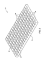
- FIG. 2 illustrates the front cover 12 having the patterned second surface 20.
- the patterned second surface 20 includes a plurality of equally spaced horizontal triangular troughs 22 and vertical triangular troughs 24 that extend through the length and width of the front cover 12.
- the horizontal and vertical triangular troughs 22, 24 intersect to form a plurality of equally spaced rectangular regions 26.
- the photovoltaic cell layer 14 (illustrated in FIG. 1) may include a plurality of photovoltaic cells and may be positioned directly below the rectangular regions 26 of the patterned second surface 20.
- the plurality of photovoltaic cells are coupled electrically and may also be embedded in a protective encapsulant (not shown).
- the protective encapsulant may include ethylene vinyl acetate.
- the protective encapsulant is configured to provide strength to the photovoltaic cells and also to protect the photovoltaic cells from extreme ambient conditions.
- FIG. 3 illustrates interaction of solar energy in the energy conversion system 10.
- a protective coating 29 is formed on the first surface 18 of the front cover 12 to reject ultraviolet light while transmitting visible light.
- the protective coating 29 is comprised of a sollx ® material.
- the protective coating 29 is provided to selectively reject ultraviolet light from reaching the encapsulant and the photovoltaic cell 15.
- the protective coating 29 may also be used to block a portion of infrared light from reaching the photovoltaic cell 15 depending on the responsivity of the photovoltaic cell 15.
- an ultraviolet absorbing material may be added to material of the front cover 12 instead of or in addition to the protective coating 29.
- a reflective layer 30 is formed on the patterned second surface 20 of the front cover 12.
- the reflective layer 30 includes a metallic coating.
- the reflective layer 30 includes a dielectric coating.
- the reflective layer 30 is configured to reflect the light rays incident on the triangular troughs 22, 24.
- light rays 28 incident on the photovoltaic cell 15 are either directly transmitted through the front cover 12 to the photovoltaic cell 15 or are reflected from the patterned second surface 20 and then reflected from the first surface 18 prior to impinging the photovoltaic cell 15.
- Light is reflected from the first surface 18 due to total internal reflection (TIR), which occurs when the angle of incidence of light rays in a medium of higher refractive index reaches an interface with a medium of lower refractive index at an angle greater than the critical angle.
- TIR total internal reflection
- the critical angle is determined based on the difference between the refractive indexes of two mutually adjacent media.
- the angle of incidence of the reflected rays on the first surface 18 is determined based on angle of incidence of the incident solar rays, angle of inclination of the triangular troughs 22, 24, and the refractive index of the material of the front cover 12.
- the angle of inclination of the triangular troughs is chosen in such a way that so as to optimize the collection efficiency of solar energy for a broad range of incident light rays for a given material.
- FIG. 4 illustrates another embodiment of the present invention and illustrates the interaction of solar energy in the energy conversion system 10.
- the system 10 includes a plurality of photovoltaic cells 15 provided inside an encapsulant 31 interposed between the front cover 12 and the back cover 16.
- the photovoltaic cell 15 is a bifacial cell as known to those skilled in the art.
- the back cover 16 includes a flat surface 21 and a patterned surface 23, in accordance with the illustrated embodiment.
- a reflective layer 27 is formed on the patterned surface 23 of the back cover 16.
- a support plate 33 e.g. polyvinyl fluoride plate
- the front cover 12, the back cover 16, and the encapsulant 31 may have similar refractive index.
- light rays incident on the bifacial photovoltaic cell 15 are either directly transmitted through the front cover 12 to the photovoltaic cell 15 or are reflected from the patterned surface 23 of the back cover 16 and then reflected from the first surface 18 of the front cover 12 prior to impinging the bifacial photovoltaic cell 15.
- light is reflected from the first surface 18 due to total internal reflection (TIR).
- TIR total internal reflection
- the light rays reflected from the patterned surface 23 of the back cover 16 may also directly impinge the bifacial photovoltaic cell 15.
- FIG. 5 illustrates another embodiment of the energy conversion system 10.
- the front cover 12 comprises glass.
- the reflective layer 30 is formed on the patterned second surface 20 of the front cover 12.
- the back cover 16 comprises a flat plate.
- the photovoltaic cell 15 is formed between the patterned second surface 20 and the back cover 16.
- FIG. 6 illustrates another embodiment of the energy conversion system 10.
- the front cover 12 comprises polycarbonate.
- the reflective layer 30 is formed on the patterned second surface 20 of the front cover 12.
- the back cover 16 comprises Noryl ® and has a patterned third surface 32 and a flat fourth surface 34, in accordance with the illustrated embodiment.
- the patterned second surface 20 and the patterned third surface 32 includes the plurality of equally spaced horizontal triangular troughs and vertical triangular troughs. The horizontal and vertical triangular troughs intersect to form the plurality of equally spaced rectangular regions as discussed above.
- the patterned second surface 20 and the patterned third surface 32 includes plurality of equally spaced horizontal triangular troughs and vertical triangular troughs, or pyramidal structures, or conical structures, or a combination thereof.
- Each photovoltaic cell 15 of the photovoltaic cell layer 14 is interposed between the patterned second surface 20 and the patterned third surface 32.
- the photovoltaic cells 15 may be embedded in the protective encapsulant 31.
- an adhesive coating or an encapsulant 36 is formed on the patterned third surface 32 of the back cover 16.
- FIG. 7 illustrates another embodiment of the energy conversion system 10.
- the front cover 12 may include glass, polycarbonate, or the like.
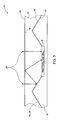
- Angle of inclination of the triangular trough ( ⁇ ) is selected based on refractive index (n c ) of the front cover 12, width (W c ) of the photovoltaic cell 15, and length (L c ) of the photovoltaic cell 15, so as to ensure total internal reflection of light rays for a broad range of light incident angles.
- light captured by the photovoltaic cell 15 may be enhanced by increasing the ratio of height (h b ) of the triangular trough to height (h c ) of the front cover 12.
- the width of the triangular trough is indicated by reference variable "W b ".
- the radius of curvature of the triangular trough is indicated by reference variable "r”.
- the triangular troughs may be coated with a metallic coating (e.g. silver coating) for reflecting the incident light rays.
- height (h c ) of the front cover 12 is equal to 5.6 mm
- height (h b ) of the triangular trough is equal to 3.6 mm
- Width (W b ) of the triangular trough is equal to 12.5 mm
- length (L c ) of the photovoltaic cell is equal to 25 mm
- width (W c ) of the photovoltaic cell is equal to 25 mm
- angle of inclination of the triangular trough ( ⁇ ) is equal to 34.5376 degrees.
- FIG. 8 illustrates a top plan view of a laminate layout of the front cover 12 having the patterned second surface 20.
- the patterned second surface 20 includes the plurality of equally spaced horizontal triangular troughs 22 and vertical triangular troughs 24 arranged in 5 rows and 19 columns.
- the length of the patterned second surface 20 is indicated by reference variable “L l ".
- the width of the patterned second surface 20 is indicated by reference variable "W l ".
- the width of photovoltaic cell is indicated by reference variable 'W c ".
- the width of the triangular troughs is indicated by the reference variable "W b “.
- “L l “ is equal to 700 mm
- W l " is equal to 175 mm
- W c " is equal to 25 mm
- “W b " is equal to 12.5 mm.
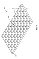
- FIG. 9 illustrates another embodiment of the front cover 12 having the patterned second surface 20.
- the patterned second surface 20 includes a plurality of equally spaced pyramidal structures 38 forming a pyramidal matrix 40.
- the plurality of photovoltaic cells 15 are located between the pyramidal structures 38.
- the light rays incident on the photovoltaic cells 15 are either directly transmitted through the front cover 12 or are reflected from the pyramidal structures 38 (reflected either once or multiple times) and then reflected from the first surface (reflected either once or multiple times as shown above) due to total internal reflection prior to impinging the photovoltaic cells 15.
- the pyramidal structures 38 are provided to accept a broad range of incident light rays and may be optimized for a broad range of photovoltaic cell sizes. As the optical concentration is low and relatively uniform across the photovoltaic cells 15, performance degradation of the photovoltaic cells 15 due to thermal effect is minimized.
- FIG. 10 illustrates another embodiment of the energy conversion system 10.
- the front cover 12 comprises a Lexan ® material.
- the photovoltaic cell 15 is provided between the patterned second surface 20 of the first cover 20 and the back cover 16.
- the patterned second surface 20 includes the plurality of pyramidal structures 38 provided with the reflective layer 30.
- the patterned second surface 20 includes plurality of equally spaced horizontal triangular troughs and vertical triangular troughs, or pyramidal structures, or conical structures, or a combination thereof.
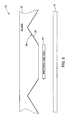
- height of the front cover 12 is indicated by reference variable "h c ".
- Height of the pyramidal structure is indicated by reference variable “h b “.
- “h c " is equal to 15.5 mm
- “h b “ is equal to 13.9 mm
- ⁇ ” is equal to 29 degrees
- W c " is equal to 50 mm
- W b “ is equal to 50 mm
- "p” is equal to 1.5 mm.
- FIG. 11 illustrates a top plan view of another embodiment of a laminate layout of the front cover 12 having the patterned second surface 20.
- the patterned second surface 20 includes the plurality of equally spaced pyramidal structures 38 forming the pyramidal matrix 40 arranged in 7 rows and 27 columns. Length of the patterned second surface 20 is indicated by reference variable "L I " and width of the patterned second surface 20 is indicated by reference variable "W I ". In one example, “L I " is equal to 1400 mm, and the "W I " is equal to 350 mm.
- FIG. 12 illustrates a top plan view of another embodiment of the laminate layout of the front cover having the patterned second surface 20.
- the patterned second surface 20 includes the plurality of equally spaced pyramidal structures 38 and conical structures 42 forming a matrix.
- the photovoltaic cells 15 are located between the pyramidal structures 38 and the conical structures 42.
- the pyramidal structures 38 and the conical structures 42 are provided to accept a broad range of incident light rays and may be optimized for a broad range of photovoltaic cell sizes.
- the patterned second surface 20 includes only a plurality of equally spaced conical structures 42 forming a matrix. Residual spaces may be formed between the conical structures 42 and the photovoltaic cells 15.
- Effect of residual spaces may be mitigated by either using a reflective coating, by forming microstructures provided with the reflective coating in the residual spaces of the front cover, or by using a reflective back layer so as to capture some of the light rays incident on the residual spaces.
- the front cover 12 illustrated in the above-mentioned embodiments provide both optical concentration and light guiding functionality.
- the optical concentration of solar energy on the photovoltaic cell 15 is both low and relatively uniform. As a result degradation in performance of the photovoltaic cells 15 due to thermal effects is reduced.
- the method includes providing the first optical cover 12 having the first flat surface 18 and the second patterned surface 20 as represented by step 44.
- the second patterned surface 20 is configured to concentrate and guide the solar energy.
- the patterned second surface 20 includes plurality of equally spaced horizontal triangular troughs 22 and vertical triangular troughs 24.
- the horizontal and vertical triangular troughs 22, 24 intersect to form plurality of equally spaced rectangular regions 26.
- the patterned second surface 20 includes plurality of equally spaced pyramidal structures 38 forming the pyramidal matrix 40.
- the patterned second surface 20 includes plurality of equally spaced conical structures 42 forming the conical matrix. In yet another embodiment, the patterned second surface may include combination of plurality of equally spaced pyramidal structures 38 and conical structures 42. The method may further include providing the reflective layer 30 on the patterned second surface 20 of the first optical cover 12 to reflect incident light rays as represented by step 46.
- the method may further include providing the protective coating 29 on the first flat surface 18 of the first optical cover 12 configured to selectively reject ultraviolet light as represented by step 48.
- the protective coating 29 may be an absorptive coating, dielectric coating or a metallic coating.
- the method further includes providing the second optical cover 16 as represented by step 50.
- the second optical cover 16 comprises a flat plate.
- the second optical cover 16 comprises the patterned third surface 32 and the flat fourth surface 34.
- the method further includes providing the photovoltaic cell layer 14 encapsulated between the second patterned surface 20 and the second optical cover 16 as represented by step 52.
- the photovoltaic cell layer 14 includes plurality of photovoltaic cells configured to receive the solar energy from the patterned second surface 20 and convert the solar energy into electrical energy.
Landscapes
- Photovoltaic Devices (AREA)
Abstract
Description
- The invention relates generally to a solar energy conversion system, and more particularly, to a photovoltaic concentrator configured to concentrate and guide incident light onto plurality of photovoltaic cells.
- Solar energy is considered as an alternate source of energy relative to other forms of energy. Solar energy conversion systems are used to convert solar energy into electrical energy. The solar energy conversion system typically includes photovoltaic modules, photoelectric cells, or solar cells that convert solar energy into electrical energy for immediate use or for storage and subsequent use. Conversion of solar energy into electrical energy includes reception of light, such as sunlight, at a solar cell, absorption of sunlight into the solar cell, generation and separation of positive and negative charges creating a voltage in the solar cell, and collection and transfer of electrical charges through a terminal coupled to the solar cell.
- Solar modules are primarily used in residential and commercial areas i.e. in areas served by a grid of an electric utility company. The amount of electrical energy generated by the solar module is directly related to the amount of solar energy the cells within a module absorb, which in turn is impacted by the cell efficiency, surface area of cell coverage, and the intensity or brightness of the sunlight that is incident on the cells. Cost of the photovoltaic module increases with increased surface area coverage by the photovoltaic cells. One approach for reducing the cost associated with photovoltaic modules is via optical concentration techniques. By employing optical concentration, the cell coverage area within the laminate is reduced. Traditional optical concentrators used for higher levels of optical concentration are often bulky and require active tracking of the light rays. Moreover cost associated with traditional optical concentrators are higher.
- Therefore, it would be advantageous to provide a low level static optical concentrator for reducing the cost associated with solar modules with minimal efficiency loss.
- In accordance with one aspect of the present invention, an energy conversion system is provided. The system includes a first optical cover having a flat surface and a patterned surface. The patterned surface is configured to receive solar energy from the flat surface, then concentrate and guide the solar energy. The system also includes a second optical cover. The system further includes a photovoltaic cell layer between the patterned surface of the first optical cover and the second optical cover. The photovoltaic cell layer is configured to receive the solar energy from the patterned surface and convert the solar energy into electrical energy.
- In accordance with another aspect of the present invention, an energy conversion system is provided. The system includes a first optical cover comprising a first surface and a second surface, wherein the first surface comprises a flat surface and the second surface comprises a patterned surface configured to receive solar energy from the first surface and further configured to concentrate and guide the solar energy. The system also includes a second optical cover comprising a third patterned surface and a fourth flat surface. The system further includes a plurality of bifacial photovoltaic cells located between the patterned surface of the first optical cover and the second optical cover and configured to receive the solar energy from the patterned surface and convert the solar energy into electrical energy. The solar energy incident on the photovoltaic cells is directly transmitted through the first optical cover, or is transmitted by reflection or total internal reflection of the first optical cover, or is transmitted by total internal reflection of the second optical cover, or a combination thereof.
- In accordance with another aspect of the present invention, a solar concentrator is provided. The solar concentrator includes a flat surface. The solar concentrator also includes a patterned surface including a plurality of mutually coupled or discrete horizontal and vertical triangular troughs or pyramidal structures, or conical structures, or a combination thereof. The solar concentrator further includes a reflective layer formed on the patterned surface.
- The invention will now be described in greater detail, by way of example, with reference to the drawings, in which:-
- FIG. 1 is a diagrammatic representation of an energy conversion system having a front optical cover, a photovoltaic cell layer, and a back optical cover in accordance with an exemplary embodiment of the present technique;
- FIG. 2 is a perspective view of the front optical cover having a patterned surface in accordance with an exemplary embodiment of the present technique;
- FIG. 3 is a diagrammatical representation illustrating interaction of solar energy in the energy conversion system in accordance with an exemplary embodiment of the present technique;
- FIG. 4 is a diagrammatical representation illustrating interaction of solar energy in the energy conversion system having a plurality of bifacial photovoltaic cells in accordance with an exemplary embodiment of the present technique;
- FIG. 5 is a diagrammatical representation of the energy conversion system having plurality of crossed triangular troughs in accordance with certain aspects of the present technique;
- FIG. 6 is a diagrammatical representation of the energy conversion system having a plurality of crossed triangular troughs in accordance with an exemplary embodiment of the present technique;
- FIG. 7 is a diagrammatical representation of the energy conversion system having plurality of crossed triangular troughs in accordance with certain aspects of the present technique;
- FIG. 8 is a top plan view of a laminate layout of the front optical cover having plurality of crossed triangular troughs in accordance with an exemplary embodiment of the present technique;
- FIG. 9 is a diagrammatical representation of the energy conversion system having a pyramidal matrix in accordance with an exemplary embodiment of the present technique;
- FIG. 10 is a diagrammatical representation of the energy conversion system having the pyramidal matrix in accordance with certain aspects of the present technique;
- FIG. 11 is a top plan view of a laminate layout of the front optical cover having plurality of pyramidal structures in accordance with an exemplary embodiment of the present technique;
- FIG. 12 is a top plan view of a laminate layout of the front optical cover having a plurality of pyramidal and conical structures in accordance with an exemplary embodiment of the present technique; and
- FIG. 13 is a flow chart illustrating a process of manufacturing an energy conversion system in accordance with an exemplary embodiment of the present technique.
- As discussed in detail below, embodiments of the present technique provide an energy conversion system having a solar concentrator configured to receive solar energy and further configured to concentrate and guide the solar energy to a photovoltaic cell layer. The solar concentrator is configured to accept light rays from a broad range of incident flux angles with minimal degradation in performance. Specifically, the solar concentrator comprises a front cover having a patterned surface configured to concentrate and guide the solar energy. In accordance with the present technique, cost per power ratio of the solar concentrator is reduced. Also techniques are disclosed in which solar energy incident on the photovoltaic cell layer is directly transmitted through the above-mentioned solar concentrator or is transmitted by total internal reflection through the solar concentrator or a combination thereof. Various embodiments of these techniques are discussed in further detail below with reference to FIGS. 1-13.
- FIG. 1 illustrates an
energy conversion system 10 including a firstoptical cover 12, aphotovoltaic cell layer 14, and a secondoptical cover 16. In the illustrated embodiment, the firstoptical cover 12 is illustrated as a front cover and the secondoptical cover 16 is a back cover. Thephotovoltaic cell layer 14 is interposed between thefront cover 12 and theback cover 16 and may comprise one or more photovoltaic cells. - The
front cover 12 may comprise a transparent material, such as glass, polycarbonate, Lexan ® material, or the like. Thefront cover 12 has afirst surface 18 and a patternedsecond surface 20. Thephotovoltaic cell layer 14 is interposed between the patternedsecond surface 20 and theback cover 16. The patternedsecond surface 20 is configured to receive solar energy from thefirst surface 18 and to concentrate and guide the solar energy to thephotovoltaic cell layer 14. The patternedsecond surface 20 may be formed using existing techniques such as glass molding, fly cutting, or the like as known to those skilled in the art. Further, thefront cover 12 may include a single piece of material, as illustrated in Fig. 1, or alternatively, may be a composite structure wherein thefirst surface 18 and patternedsecond surface 20 are fabricated separately and subsequently coupled together to form thefront cover 12. The structure of the patternedsecond surface 20 is explained in greater detail below. Thephotovoltaic cell layer 14 includes semiconductor materials known to those skilled in the art. Thephotovoltaic cell layer 12 is configured to receive the solar energy from the patternedsecond surface 20 and convert the solar energy into electrical energy. Theback cover 16 may comprise glass, polyvinyl fluoride film, polycarbonate, Noryl ®, Lexan ® material, or the like. Theback cover 16 may be used as an optical cover or as a support plate. - FIG. 2 illustrates the
front cover 12 having the patternedsecond surface 20. In the illustrated embodiment, the patternedsecond surface 20 includes a plurality of equally spaced horizontaltriangular troughs 22 and verticaltriangular troughs 24 that extend through the length and width of thefront cover 12. The horizontal and verticaltriangular troughs rectangular regions 26. The photovoltaic cell layer 14 (illustrated in FIG. 1) may include a plurality of photovoltaic cells and may be positioned directly below therectangular regions 26 of the patternedsecond surface 20. The plurality of photovoltaic cells are coupled electrically and may also be embedded in a protective encapsulant (not shown). For example, the protective encapsulant may include ethylene vinyl acetate. The protective encapsulant is configured to provide strength to the photovoltaic cells and also to protect the photovoltaic cells from extreme ambient conditions. - FIG. 3 illustrates interaction of solar energy in the
energy conversion system 10. In the illustrated embodiment, aprotective coating 29 is formed on thefirst surface 18 of thefront cover 12 to reject ultraviolet light while transmitting visible light. In one example, theprotective coating 29 is comprised of a sollx ® material. Theprotective coating 29 is provided to selectively reject ultraviolet light from reaching the encapsulant and thephotovoltaic cell 15. Theprotective coating 29 may also be used to block a portion of infrared light from reaching thephotovoltaic cell 15 depending on the responsivity of thephotovoltaic cell 15. In another embodiment, an ultraviolet absorbing material may be added to material of thefront cover 12 instead of or in addition to theprotective coating 29. Areflective layer 30 is formed on the patternedsecond surface 20 of thefront cover 12. In one embodiment, thereflective layer 30 includes a metallic coating. In another embodiment, thereflective layer 30 includes a dielectric coating. Thereflective layer 30 is configured to reflect the light rays incident on thetriangular troughs - In one example, light rays 28 incident on the
photovoltaic cell 15, are either directly transmitted through thefront cover 12 to thephotovoltaic cell 15 or are reflected from the patternedsecond surface 20 and then reflected from thefirst surface 18 prior to impinging thephotovoltaic cell 15. Light is reflected from thefirst surface 18 due to total internal reflection (TIR), which occurs when the angle of incidence of light rays in a medium of higher refractive index reaches an interface with a medium of lower refractive index at an angle greater than the critical angle. As known to those skilled in the art, the critical angle is determined based on the difference between the refractive indexes of two mutually adjacent media. In the illustrated embodiment, the angle of incidence of the reflected rays on thefirst surface 18 is determined based on angle of incidence of the incident solar rays, angle of inclination of thetriangular troughs front cover 12. The angle of inclination of the triangular troughs is chosen in such a way that so as to optimize the collection efficiency of solar energy for a broad range of incident light rays for a given material. - FIG. 4 illustrates another embodiment of the present invention and illustrates the interaction of solar energy in the
energy conversion system 10. In accordance with the embodiment illustrated in Fig. 4, thesystem 10 includes a plurality ofphotovoltaic cells 15 provided inside anencapsulant 31 interposed between thefront cover 12 and theback cover 16. In the illustrated embodiment, thephotovoltaic cell 15 is a bifacial cell as known to those skilled in the art. Theback cover 16 includes aflat surface 21 and apatterned surface 23, in accordance with the illustrated embodiment. Areflective layer 27 is formed on the patternedsurface 23 of theback cover 16. A support plate 33 (e.g. polyvinyl fluoride plate) may be provided to support theback cover 16. Thefront cover 12, theback cover 16, and theencapsulant 31 may have similar refractive index. - In illustrated embodiment, light rays incident on the bifacial
photovoltaic cell 15, are either directly transmitted through thefront cover 12 to thephotovoltaic cell 15 or are reflected from the patternedsurface 23 of theback cover 16 and then reflected from thefirst surface 18 of thefront cover 12 prior to impinging the bifacialphotovoltaic cell 15. As discussed above, light is reflected from thefirst surface 18 due to total internal reflection (TIR). The light rays reflected from the patternedsurface 23 of theback cover 16 may also directly impinge the bifacialphotovoltaic cell 15. - FIG. 5 illustrates another embodiment of the
energy conversion system 10. In the illustrated embodiment, thefront cover 12 comprises glass. As noted above, thereflective layer 30 is formed on the patternedsecond surface 20 of thefront cover 12. Theback cover 16 comprises a flat plate. Thephotovoltaic cell 15 is formed between the patternedsecond surface 20 and theback cover 16. - FIG. 6 illustrates another embodiment of the
energy conversion system 10. In the illustrated embodiment, thefront cover 12 comprises polycarbonate. As illustrated above, thereflective layer 30 is formed on the patternedsecond surface 20 of thefront cover 12. Theback cover 16 comprises Noryl ® and has a patternedthird surface 32 and a flatfourth surface 34, in accordance with the illustrated embodiment. In the illustrated embodiment, the patternedsecond surface 20 and the patternedthird surface 32 includes the plurality of equally spaced horizontal triangular troughs and vertical triangular troughs. The horizontal and vertical triangular troughs intersect to form the plurality of equally spaced rectangular regions as discussed above. In another example, the patternedsecond surface 20 and the patternedthird surface 32 includes plurality of equally spaced horizontal triangular troughs and vertical triangular troughs, or pyramidal structures, or conical structures, or a combination thereof. Eachphotovoltaic cell 15 of thephotovoltaic cell layer 14 is interposed between the patternedsecond surface 20 and the patternedthird surface 32. Thephotovoltaic cells 15 may be embedded in theprotective encapsulant 31. In the illustrated embodiment, an adhesive coating or anencapsulant 36 is formed on the patternedthird surface 32 of theback cover 16. - FIG. 7 illustrates another embodiment of the
energy conversion system 10. As discussed above, thefront cover 12 may include glass, polycarbonate, or the like. Angle of inclination of the triangular trough (θ) is selected based on refractive index (nc) of thefront cover 12, width (Wc) of thephotovoltaic cell 15, and length (Lc) of thephotovoltaic cell 15, so as to ensure total internal reflection of light rays for a broad range of light incident angles. In the illustrated embodiment, light captured by thephotovoltaic cell 15 may be enhanced by increasing the ratio of height (hb) of the triangular trough to height (hc) of thefront cover 12. The width of the triangular trough is indicated by reference variable "Wb". The radius of curvature of the triangular trough is indicated by reference variable "r". The triangular troughs may be coated with a metallic coating (e.g. silver coating) for reflecting the incident light rays. - In one example, for 48% cell coverage of the
energy conversion system 10, height (hc) of thefront cover 12 is equal to 5.6 mm, height (hb) of the triangular trough is equal to 3.6 mm, Width (Wb) of the triangular trough is equal to 12.5 mm, length (Lc) of the photovoltaic cell is equal to 25 mm, width (Wc) of the photovoltaic cell is equal to 25 mm, and angle of inclination of the triangular trough (θ) is equal to 34.5376 degrees. - FIG. 8 illustrates a top plan view of a laminate layout of the
front cover 12 having the patternedsecond surface 20. In the illustrated embodiment, the patternedsecond surface 20 includes the plurality of equally spaced horizontaltriangular troughs 22 and verticaltriangular troughs 24 arranged in 5 rows and 19 columns. The length of the patternedsecond surface 20 is indicated by reference variable "Ll". The width of the patternedsecond surface 20 is indicated by reference variable "Wl". The width of photovoltaic cell is indicated by reference variable 'Wc". The width of the triangular troughs is indicated by the reference variable "Wb". In one example, "Ll " is equal to 700 mm, "Wl" is equal to 175 mm, " Wc" is equal to 25 mm, and "Wb" is equal to 12.5 mm. - FIG. 9 illustrates another embodiment of the
front cover 12 having the patternedsecond surface 20. The patternedsecond surface 20 includes a plurality of equally spacedpyramidal structures 38 forming apyramidal matrix 40. The plurality ofphotovoltaic cells 15 are located between thepyramidal structures 38. As illustrated in the previous embodiment, the light rays incident on thephotovoltaic cells 15 are either directly transmitted through thefront cover 12 or are reflected from the pyramidal structures 38 (reflected either once or multiple times) and then reflected from the first surface (reflected either once or multiple times as shown above) due to total internal reflection prior to impinging thephotovoltaic cells 15. Thepyramidal structures 38 are provided to accept a broad range of incident light rays and may be optimized for a broad range of photovoltaic cell sizes. As the optical concentration is low and relatively uniform across thephotovoltaic cells 15, performance degradation of thephotovoltaic cells 15 due to thermal effect is minimized. - FIG. 10 illustrates another embodiment of the
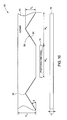
energy conversion system 10. In the illustrated embodiment, thefront cover 12 comprises a Lexan ® material. Thephotovoltaic cell 15 is provided between the patternedsecond surface 20 of thefirst cover 20 and theback cover 16. The patternedsecond surface 20 includes the plurality ofpyramidal structures 38 provided with thereflective layer 30. In another example, the patternedsecond surface 20 includes plurality of equally spaced horizontal triangular troughs and vertical triangular troughs, or pyramidal structures, or conical structures, or a combination thereof. - In the illustrated embodiment, height of the
front cover 12 is indicated by reference variable "hc". Height of the pyramidal structure is indicated by reference variable "hb". Angle of inclination of the pyramidal structure indicated by reference variable "θ". Width of the photovoltaic cell indicated by reference variable "Wc". Width of the pyramidal structure indicated by reference variable "Wb", and thickness of the back cover indicated by reference variable "p". In one example, "hc" is equal to 15.5 mm, "hb" is equal to 13.9 mm, "θ" is equal to 29 degrees, "Wc" is equal to 50 mm, "Wb" is equal to 50 mm, and "p" is equal to 1.5 mm. - FIG. 11 illustrates a top plan view of another embodiment of a laminate layout of the
front cover 12 having the patternedsecond surface 20. In the illustrated embodiment, the patternedsecond surface 20 includes the plurality of equally spacedpyramidal structures 38 forming thepyramidal matrix 40 arranged in 7 rows and 27 columns. Length of the patternedsecond surface 20 is indicated by reference variable "LI" and width of the patternedsecond surface 20 is indicated by reference variable "WI". In one example, "LI" is equal to 1400 mm, and the "WI" is equal to 350 mm. - FIG. 12 illustrates a top plan view of another embodiment of the laminate layout of the front cover having the patterned
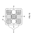
second surface 20. The patternedsecond surface 20 includes the plurality of equally spacedpyramidal structures 38 andconical structures 42 forming a matrix. Thephotovoltaic cells 15 are located between thepyramidal structures 38 and theconical structures 42. Thepyramidal structures 38 and theconical structures 42 are provided to accept a broad range of incident light rays and may be optimized for a broad range of photovoltaic cell sizes. In another embodiment, the patternedsecond surface 20 includes only a plurality of equally spacedconical structures 42 forming a matrix. Residual spaces may be formed between theconical structures 42 and thephotovoltaic cells 15. Effect of residual spaces may be mitigated by either using a reflective coating, by forming microstructures provided with the reflective coating in the residual spaces of the front cover, or by using a reflective back layer so as to capture some of the light rays incident on the residual spaces. Thefront cover 12 illustrated in the above-mentioned embodiments, provide both optical concentration and light guiding functionality. The optical concentration of solar energy on thephotovoltaic cell 15 is both low and relatively uniform. As a result degradation in performance of thephotovoltaic cells 15 due to thermal effects is reduced. - Referring to FIG. 13, a flow chart illustrating a method of manufacturing the
energy conversion system 10 in accordance with embodiments of the present technique is provided. The method includes providing the firstoptical cover 12 having the firstflat surface 18 and the second patternedsurface 20 as represented bystep 44. The second patternedsurface 20 is configured to concentrate and guide the solar energy. In the one embodiment, the patternedsecond surface 20 includes plurality of equally spaced horizontaltriangular troughs 22 and verticaltriangular troughs 24. The horizontal and verticaltriangular troughs rectangular regions 26. In another embodiment, the patternedsecond surface 20 includes plurality of equally spacedpyramidal structures 38 forming thepyramidal matrix 40. In another embodiment, the patternedsecond surface 20 includes plurality of equally spacedconical structures 42 forming the conical matrix. In yet another embodiment, the patterned second surface may include combination of plurality of equally spacedpyramidal structures 38 andconical structures 42. The method may further include providing thereflective layer 30 on the patternedsecond surface 20 of the firstoptical cover 12 to reflect incident light rays as represented bystep 46. - The method may further include providing the
protective coating 29 on the firstflat surface 18 of the firstoptical cover 12 configured to selectively reject ultraviolet light as represented bystep 48. Theprotective coating 29 may be an absorptive coating, dielectric coating or a metallic coating. The method further includes providing the secondoptical cover 16 as represented bystep 50. In one embodiment, the secondoptical cover 16 comprises a flat plate. In another embodiment, the secondoptical cover 16 comprises the patternedthird surface 32 and the flatfourth surface 34. The method further includes providing thephotovoltaic cell layer 14 encapsulated between the second patternedsurface 20 and the secondoptical cover 16 as represented bystep 52. Thephotovoltaic cell layer 14 includes plurality of photovoltaic cells configured to receive the solar energy from the patternedsecond surface 20 and convert the solar energy into electrical energy.
Claims (10)
- An energy conversion system (10), comprising:a first optical cover (12) comprising a first surface (18) and a second surface (20), wherein the first surface (18) comprises a flat surface and the second surface (20) comprises a patterned surface configured to receive solar energy from the first surface (18) and further configured to concentrate and guide the solar energy;a second optical cover (16); anda plurality of photovoltaic cells (15) located between the patterned surface (20) of the first optical cover (12) and the second optical cover (16) and configured to receive the solar energy from the patterned surface (20) and convert the solar energy into electrical energy.
- The system (10) of claim 1, further comprising a reflective layer (30) coated on the patterned surface (20) of the first optical cover (12).
- The system (10) of claim 1 or 2, wherein the patterned surface (20) comprises a plurality of equally spaced horizontal and vertical triangular troughs (22, 24) intersecting to form a plurality of equally spaced rectangular regions (26).
- The system (10) of claim 1 or 2, wherein the patterned surface (20) comprises an equally spaced pyramidal matrix (40).
- The system (10) of claim 1 or 2, wherein the patterned surface (20) comprises a combination of pyramidal and conical structures (38, 42).
- The system (10) of any preceding claim, wherein the plurality of photovoltaic cells (15) are embedded in a protective encapsulant (31).
- The system (10) ofany preceding claim, further comprising a protective coating (29) formed on the flat surface (18) of the first cover (12) to selectively transmit visible light to the plurality of photovoltaic cells (15).
- The system (10) of any preceding claim, wherein solar energy incident on the photovoltaic cells (15) is directly transmitted through the first optical cover (12), or is transmitted by total internal reflection of the first optical cover (12), or a combination thereof.
- An energy conversion system (10), comprising:a first optical cover (12) comprising a first surface (18) and a second surface (20), wherein the first surface (18) comprises a flat surface and the second surface (20) comprises a patterned surface configured to receive solar energy from the first surface (18) and further configured to concentrate and guide the solar energy;a second optical cover (16) comprising a third surface (32) and a fourth surface (34), wherein the third surface (32) comprises a patterned surface and the fourth surface (34) comprises a flat surface; anda plurality of bifacial photovoltaic cells (15) located between the patterned surface (20) of the first optical cover (12) and the second optical cover (16) and configured to receive the solar energy from the patterned surface (20, 32) and convert the solar energy into electrical energy,wherein solar energy incident on the photovoltaic cells (15) is directly transmitted through the first optical cover (12), or is transmitted by total internal reflection of the first optical cover (12), or is transmitted by total internal reflection of the second optical cover (16), or a combination thereof.
- The system (10) of claim 9, wherein the plurality of bifacial photovoltaic cells (15) are embedded in a protective encapsulant (31).
Applications Claiming Priority (1)
| Application Number | Priority Date | Filing Date | Title |
|---|---|---|---|
| US11/146,875 US8039731B2 (en) | 2005-06-06 | 2005-06-06 | Photovoltaic concentrator for solar energy system |
Publications (1)
| Publication Number | Publication Date |
|---|---|
| EP1732141A1 true EP1732141A1 (en) | 2006-12-13 |
Family
ID=36861570
Family Applications (1)
| Application Number | Title | Priority Date | Filing Date |
|---|---|---|---|
| EP06252718A Ceased EP1732141A1 (en) | 2005-06-06 | 2006-05-25 | Optical concentrator for solar cells |
Country Status (4)
| Country | Link |
|---|---|
| US (1) | US8039731B2 (en) |
| EP (1) | EP1732141A1 (en) |
| JP (1) | JP2006344964A (en) |
| CN (1) | CN100539208C (en) |
Cited By (30)
| Publication number | Priority date | Publication date | Assignee | Title |
|---|---|---|---|---|
| USD555084S1 (en) | 2005-11-18 | 2007-11-13 | Solaria Corporation | Circular solar cell package design |
| USD555083S1 (en) | 2005-11-08 | 2007-11-13 | Solaria Corporation | Solar cell package design |
| USD558139S1 (en) | 2005-11-18 | 2007-12-25 | Solaria Corporation | Triangular solar cell design |
| USD559174S1 (en) | 2005-11-18 | 2008-01-08 | Solaria Corporation | Shaped solar cell package design |
| USD568238S1 (en) | 2005-11-18 | 2008-05-06 | Solaria Corporation | Rectangular solar cell package design |
| US7419377B1 (en) | 2007-08-20 | 2008-09-02 | Solaria Corporation | Electrical coupling device and method for solar cells |
| WO2009032850A1 (en) * | 2007-09-05 | 2009-03-12 | Solaria Corporation | Notch structure for concentrating module and method of manufacture using photovoltaic strips |
| USD588534S1 (en) | 2007-07-26 | 2009-03-17 | Solaria Corporation | Shaped solar cell package |
| USD591229S1 (en) | 2008-01-24 | 2009-04-28 | Solaria Corporation | Shaped solar cell package |
| WO2009064701A1 (en) * | 2007-11-16 | 2009-05-22 | Qualcomm Mems Technologies, Inc. | Thin film solar concentrator/collector |
| WO2009064625A3 (en) * | 2007-11-14 | 2009-07-16 | Solfocus Inc | Solar cell package for solar concentrator |
| DE102008035575A1 (en) * | 2008-07-30 | 2010-02-11 | Concentrix Solar Gmbh | Photovoltaic device for the direct conversion of solar energy into electrical energy |
| WO2010143096A3 (en) * | 2009-06-10 | 2011-02-17 | Koninklijke Philips Electronics N.V. | Solar cells and their manufacture |
| US7910392B2 (en) | 2007-04-02 | 2011-03-22 | Solaria Corporation | Method and system for assembling a solar cell package |
| US7910822B1 (en) | 2005-10-17 | 2011-03-22 | Solaria Corporation | Fabrication process for photovoltaic cell |
| US7910035B2 (en) | 2007-12-12 | 2011-03-22 | Solaria Corporation | Method and system for manufacturing integrated molded concentrator photovoltaic device |
| US8227688B1 (en) | 2005-10-17 | 2012-07-24 | Solaria Corporation | Method and resulting structure for assembling photovoltaic regions onto lead frame members for integration on concentrating elements for solar cells |
| EP2328185A4 (en) * | 2009-09-28 | 2012-08-08 | Toyota Motor Co Ltd | METHOD FOR MANUFACTURING SOLAR CELL MODULE AND PRECURSOR FOR SOLAR CELL MODULE |
| EP2395557A3 (en) * | 2010-06-08 | 2013-03-27 | DelSolar (Wujiang) Ltd. | Solar cell module and method of fabricating the same |
| ITMI20112294A1 (en) * | 2011-12-16 | 2013-06-17 | Fond Ct Internaz Della Fotonica P | OPTICAL CONCENTRATOR |
| USD699176S1 (en) | 2011-06-02 | 2014-02-11 | Solaria Corporation | Fastener for solar modules |
| WO2014114286A1 (en) * | 2013-01-28 | 2014-07-31 | Curto, Vincenzo Gabriele | Reflection surface arrangement for photovoltaic systems |
| WO2014138857A1 (en) | 2013-03-15 | 2014-09-18 | John Paul Morgan | Light panel, optical assembly with improved interface and light panel with improved manufacturing tolerances |
| US8902484B2 (en) | 2010-12-15 | 2014-12-02 | Qualcomm Mems Technologies, Inc. | Holographic brightness enhancement film |
| US8941631B2 (en) | 2007-11-16 | 2015-01-27 | Qualcomm Mems Technologies, Inc. | Simultaneous light collection and illumination on an active display |
| US8979349B2 (en) | 2009-05-29 | 2015-03-17 | Qualcomm Mems Technologies, Inc. | Illumination devices and methods of fabrication thereof |
| EP2827378A4 (en) * | 2012-03-16 | 2015-11-04 | Sanyo Electric Co | SOLAR CELL MODULE |
| EP3073536A1 (en) * | 2015-03-25 | 2016-09-28 | Kabushiki Kaisha Toyota Jidoshokki | Solar battery module |
| US10186625B2 (en) * | 2013-12-27 | 2019-01-22 | Byd Company Limited | Double-glass photovoltaic cell module |
| WO2022258868A1 (en) | 2021-06-07 | 2022-12-15 | Universidad De Jaén | Semi-transparent bifacial photovoltaic module with rear irradiance concentrators |
Families Citing this family (86)
| Publication number | Priority date | Publication date | Assignee | Title |
|---|---|---|---|---|
| CN101553935B (en) * | 2006-11-17 | 2011-01-19 | 京半导体股份有限公司 | Stacked solar cell device |
| DE202007002897U1 (en) * | 2007-02-28 | 2008-07-10 | SCHÜCO International KG | Photovoltaic solar module |
| US9040808B2 (en) * | 2007-05-01 | 2015-05-26 | Morgan Solar Inc. | Light-guide solar panel and method of fabrication thereof |
| US8119902B2 (en) * | 2007-05-21 | 2012-02-21 | Solaria Corporation | Concentrating module and method of manufacture for photovoltaic strips |
| GB2449504A (en) * | 2007-05-25 | 2008-11-26 | Renewable Energy Corp Asa | Photovoltaic module with reflective V-grooves |
| US8707736B2 (en) * | 2007-08-06 | 2014-04-29 | Solaria Corporation | Method and apparatus for manufacturing solar concentrators using glass process |
| CN101868861B (en) * | 2007-09-13 | 2013-01-02 | 加斯·戴 | Three dimensional photo voltaic modules in an energy reception panel |
| US20090114212A1 (en) * | 2007-10-06 | 2009-05-07 | The Research Foundation Of The State University Of New York | Hybrid solar panel |
| CN101431115B (en) * | 2007-11-07 | 2011-05-18 | E.I.内穆尔杜邦公司 | Solar cell panel and manufacturing method thereof |
| CN101897037B (en) * | 2007-12-10 | 2012-09-26 | 丰田自动车株式会社 | Solar cell module |
| US8168884B2 (en) * | 2008-01-04 | 2012-05-01 | Solaria Corporation | Solar cell structure including a plurality of concentrator elements with a notch design and predetermined radii and method |
| KR20090081950A (en) * | 2008-01-25 | 2009-07-29 | 삼성전자주식회사 | Solar cell and manufacturing method thereof |
| FR2928147B1 (en) * | 2008-02-29 | 2011-04-01 | Saint Gobain | TEXTURE SUBSTRATE WITH STACK WITH THERMAL PROPERTIES |
| US20090250093A1 (en) * | 2008-04-08 | 2009-10-08 | Zupei Chen | Enhanced concentrator PV pannel |
| US8153888B2 (en) * | 2008-05-01 | 2012-04-10 | Northrop Grumman Systems Corporation | Lateral ultra-high efficiency solar cell |
| US20090314330A1 (en) * | 2008-06-24 | 2009-12-24 | Moser Baer Photovoltaic Limited | Photovoltaic module |
| US20090314334A1 (en) * | 2008-06-24 | 2009-12-24 | Moser Baer Photovoltaic Limited | Electronic substrate for a photovoltaic module |
| US20090314326A1 (en) * | 2008-06-24 | 2009-12-24 | Moser Baer Photovoltaic Limited | Photovoltaic module |
| US20100024805A1 (en) * | 2008-07-29 | 2010-02-04 | Genie Lens Technologies, Llc | Solar panels for concentrating, capturing, and transmitting solar energy in conversion systems |
| US20100024866A1 (en) * | 2008-07-31 | 2010-02-04 | General Electric Company | Solar energy concentrator |
| US8184372B1 (en) * | 2008-09-04 | 2012-05-22 | Bingwu Gu | Low numerical aperture (low-NA) solar lighting system |
| FR2938078B1 (en) | 2008-11-03 | 2011-02-11 | Saint Gobain | GLAZING WITH ZONES CONCENTRATING THE LIGHT BY IONIC EXCHANGE. |
| CN103545394A (en) * | 2008-11-19 | 2014-01-29 | 凸版印刷株式会社 | Light reuse sheet, solar battery module, and light source module |
| JP4706759B2 (en) * | 2009-01-23 | 2011-06-22 | トヨタ自動車株式会社 | Solar cell |
| US8173890B2 (en) * | 2009-01-26 | 2012-05-08 | Solaria Corporation | Solar cell structure including a plurality of concentrator elements with a notch design and predetermined RADII and method |
| US20100294338A1 (en) * | 2009-02-20 | 2010-11-25 | Solaria Corporation | Large Area Concentrator Lens Structure and Method |
| WO2010144867A1 (en) * | 2009-06-11 | 2010-12-16 | Energy Focus, Inc. | Method of making solar collector assemblies with optical concentrator encapsulant |
| JP2012532447A (en) | 2009-06-30 | 2012-12-13 | ピルキントン グループ リミテッド | Double-sided photovoltaic module having a reflective element and method for manufacturing the same |
| JP2011096718A (en) * | 2009-10-27 | 2011-05-12 | Toyota Motor Corp | Solar cell module |
| JP5218670B2 (en) * | 2009-11-06 | 2013-06-26 | トヨタ自動車株式会社 | Solar cell module |
| US9012766B2 (en) | 2009-11-12 | 2015-04-21 | Silevo, Inc. | Aluminum grid as backside conductor on epitaxial silicon thin film solar cells |
| WO2011065571A1 (en) * | 2009-11-30 | 2011-06-03 | 京セラ株式会社 | Photoelectric conversion module, method for manufacturing same, and power generation device |
| FR2954000B1 (en) * | 2009-12-14 | 2012-01-06 | Commissariat Energie Atomique | REFLECTIVE DEVICE FOR PHOTOVOLTAIC MODULE WITH BIFACIAL CELLS |
| FR2953998B1 (en) * | 2009-12-14 | 2012-03-30 | Commissariat Energie Atomique | PHOTOVOLTAIC MODULE WITH ELECTRICAL CONNECTION HAVING OPTICAL FUNCTION |
| EP2372785A1 (en) * | 2010-04-02 | 2011-10-05 | Tata Steel Nederland Technology B.V. | Solar panel with polymer body and method to manufacture such solar panel |
| CN101866972A (en) * | 2010-05-18 | 2010-10-20 | 扬州旭博光伏科技有限公司 | Integral component of solar cell and radiator |
| US9214576B2 (en) | 2010-06-09 | 2015-12-15 | Solarcity Corporation | Transparent conducting oxide for photovoltaic devices |
| CN102315293B (en) * | 2010-06-30 | 2013-09-04 | 财团法人工业技术研究院 | Solar photovoltaic module encapsulation laminated structure and manufacturing method thereof |
| CN102315796A (en) * | 2010-07-05 | 2012-01-11 | 郭保光 | The flat photovoltaic transducer of modified model |
| US8735791B2 (en) | 2010-07-13 | 2014-05-27 | Svv Technology Innovations, Inc. | Light harvesting system employing microstructures for efficient light trapping |
| US9773928B2 (en) | 2010-09-10 | 2017-09-26 | Tesla, Inc. | Solar cell with electroplated metal grid |
| US9800053B2 (en) | 2010-10-08 | 2017-10-24 | Tesla, Inc. | Solar panels with integrated cell-level MPPT devices |
| TWI445194B (en) * | 2010-12-06 | 2014-07-11 | Ind Tech Res Inst | Package structure of solar photovoltaic module and method of manufacturing the same |
| WO2012075545A1 (en) * | 2010-12-10 | 2012-06-14 | University Of Wollongong | Improvements related to multi-layer, light-modulating devices and the manufacture thereof |
| AU2011340809A1 (en) | 2010-12-10 | 2013-06-13 | Aquahydrex Pty Ltd | Multi-layer water- splitting devices |
| US20120234371A1 (en) * | 2011-03-18 | 2012-09-20 | Tong Zhang | Incident angle dependent smart solar concentrator |
| GB2491091A (en) * | 2011-04-19 | 2012-11-28 | Gm Innovations Ltd | A solar panel with corrugated transparent layer for reflecting and concentrating incoming light |
| US9054256B2 (en) | 2011-06-02 | 2015-06-09 | Solarcity Corporation | Tunneling-junction solar cell with copper grid for concentrated photovoltaic application |
| JP2013065708A (en) * | 2011-09-16 | 2013-04-11 | Keiwa Inc | Solar cell module, back sheet for solar cell module, spacer for arrangement between solar cells, and manufacturing method of solar cell module |
| US8614842B2 (en) | 2011-11-14 | 2013-12-24 | Prism Solar Technologies Incorporated | Volume hologram replicator for transmission type gratings |
| US20130167903A1 (en) * | 2011-11-14 | 2013-07-04 | Prism Solar Technologies Incorporated | Encapsulated solar energy concentrator |
| WO2013078209A1 (en) * | 2011-11-23 | 2013-05-30 | Prism Solar Technologies Incorporated | Encapsulated solar energy concentrator |
| US20130160850A1 (en) * | 2011-12-09 | 2013-06-27 | Prism Solar Technologies Incorporated | Blazed grating for solar energy concentration |
| AU2012382382A1 (en) | 2012-06-12 | 2015-01-15 | Aquahydrex Pty Ltd | Breathable electrode and method for use in water splitting |
| JP2014067925A (en) * | 2012-09-26 | 2014-04-17 | Toshiba Corp | Solar battery module |
| US9865754B2 (en) | 2012-10-10 | 2018-01-09 | Tesla, Inc. | Hole collectors for silicon photovoltaic cells |
| US9812590B2 (en) * | 2012-10-25 | 2017-11-07 | Sunpower Corporation | Bifacial solar cell module with backside reflector |
| JP6010759B2 (en) * | 2012-11-19 | 2016-10-19 | パナソニックIpマネジメント株式会社 | Solar cell module |
| US9219174B2 (en) | 2013-01-11 | 2015-12-22 | Solarcity Corporation | Module fabrication of solar cells with low resistivity electrodes |
| US9412884B2 (en) | 2013-01-11 | 2016-08-09 | Solarcity Corporation | Module fabrication of solar cells with low resistivity electrodes |
| US10074755B2 (en) | 2013-01-11 | 2018-09-11 | Tesla, Inc. | High efficiency solar panel |
| WO2014138932A1 (en) * | 2013-03-15 | 2014-09-18 | Morgan Solar Inc. | Photovoltaic system |
| US8853522B1 (en) * | 2013-03-15 | 2014-10-07 | Bingwu Gu | Concentrated photovoltaic and solar heating system |
| US9595627B2 (en) | 2013-03-15 | 2017-03-14 | John Paul Morgan | Photovoltaic panel |
| WO2014162790A1 (en) * | 2013-04-05 | 2014-10-09 | 三菱電機株式会社 | Photoelectric conversion apparatus |
| CN104134705A (en) * | 2013-05-03 | 2014-11-05 | 常州亚玛顿股份有限公司 | High-efficiency solar cell module |
| KR102113839B1 (en) * | 2013-07-29 | 2020-05-21 | 엘지전자 주식회사 | Back sheet and solar cell module including the same |
| KR20160040614A (en) | 2013-07-31 | 2016-04-14 | 아쿠아하이드렉스 프로프라이어터리 리미티드 | Electro-synthetic or electro-energy cell with gas diffusion electrode(s) |
| US10309012B2 (en) | 2014-07-03 | 2019-06-04 | Tesla, Inc. | Wafer carrier for reducing contamination from carbon particles and outgassing |
| US20160020351A1 (en) * | 2014-07-18 | 2016-01-21 | Prism Solar Technologies Incorporated | Bifacial-cell-based solar-energy converting system |
| US20160064588A1 (en) * | 2014-08-28 | 2016-03-03 | James B. Paull | Concentrator lens for directing light to a photovoltaic target or mirrored surface and a dynamic window apparatus utilizing the same |
| ES2571653B1 (en) * | 2014-09-30 | 2017-03-16 | Salvador PONCE ALCÁNTARA | Transparent photovoltaic sheet with reflective bands and solar module that includes such a sheet |
| US9899546B2 (en) | 2014-12-05 | 2018-02-20 | Tesla, Inc. | Photovoltaic cells with electrodes adapted to house conductive paste |
| US9947822B2 (en) * | 2015-02-02 | 2018-04-17 | Tesla, Inc. | Bifacial photovoltaic module using heterojunction solar cells |
| US9761744B2 (en) | 2015-10-22 | 2017-09-12 | Tesla, Inc. | System and method for manufacturing photovoltaic structures with a metal seed layer |
| US20170133979A1 (en) * | 2015-11-05 | 2017-05-11 | Solarworld Ag | Photovoltaic apparatus and system comprising rotatable solar panel and reflector |
| US9842956B2 (en) | 2015-12-21 | 2017-12-12 | Tesla, Inc. | System and method for mass-production of high-efficiency photovoltaic structures |
| US10115838B2 (en) | 2016-04-19 | 2018-10-30 | Tesla, Inc. | Photovoltaic structures with interlocking busbars |
| CN107833935A (en) * | 2016-09-14 | 2018-03-23 | 海口未来技术研究院 | Solar cell module and aerostatics |
| US10672919B2 (en) | 2017-09-19 | 2020-06-02 | Tesla, Inc. | Moisture-resistant solar cells for solar roof tiles |
| US11190128B2 (en) | 2018-02-27 | 2021-11-30 | Tesla, Inc. | Parallel-connected solar roof tile modules |
| CN108363235B (en) * | 2018-03-02 | 2024-02-09 | 京东方科技集团股份有限公司 | Antireflection film, preparation method thereof, array substrate and display device |
| US11489488B2 (en) | 2018-04-13 | 2022-11-01 | Nextracker Llc | Light management systems for optimizing performance of bifacial solar module |
| FR3084967A1 (en) * | 2018-08-08 | 2020-02-14 | Total Sa | PHOTOVOLTAIC MODULE HAVING A PATTERN |
| CA3127358A1 (en) | 2019-02-01 | 2020-08-06 | Aquahydrex, Inc. | Electrochemical system with confined electrolyte |
| WO2025171330A1 (en) * | 2024-02-08 | 2025-08-14 | Vanse Corporation | Increased power output photovoltaic system |
Citations (7)
| Publication number | Priority date | Publication date | Assignee | Title |
|---|---|---|---|---|
| EP0021027A1 (en) * | 1979-07-03 | 1981-01-07 | Licentia Patent-Verwaltungs-GmbH | Solar cells arrangement |
| EP0029721A1 (en) * | 1979-11-26 | 1981-06-03 | Exxon Research And Engineering Company | Solar cell modules |
| US5240510A (en) * | 1991-09-23 | 1993-08-31 | Development Products Inc. | Photovoltaic cell |
| US5261970A (en) * | 1992-04-08 | 1993-11-16 | Sverdrup Technology, Inc. | Optoelectronic and photovoltaic devices with low-reflectance surfaces |
| US5782993A (en) * | 1996-06-28 | 1998-07-21 | Ponewash; Jackie | Photovoltaic cells having micro-embossed optical enhancing structures |
| WO1999009601A1 (en) * | 1997-08-19 | 1999-02-25 | Daystar Technologies, Inc. | Reflective concentrating solar cell assembly |
| US20030140960A1 (en) * | 2002-01-29 | 2003-07-31 | Avi Baum | System and method for converting solar energy to electricity |
Family Cites Families (16)
| Publication number | Priority date | Publication date | Assignee | Title |
|---|---|---|---|---|
| US4240692A (en) * | 1975-12-17 | 1980-12-23 | The University Of Chicago | Energy transmission |
| JPS56118377A (en) * | 1980-02-21 | 1981-09-17 | Nec Corp | Solar cell module |
| US5080725A (en) | 1987-12-17 | 1992-01-14 | Unisearch Limited | Optical properties of solar cells using tilted geometrical features |
| US6020553A (en) * | 1994-10-09 | 2000-02-01 | Yeda Research And Development Co., Ltd. | Photovoltaic cell system and an optical structure therefor |
| US5735966A (en) * | 1995-05-15 | 1998-04-07 | Luch; Daniel | Substrate structures for integrated series connected photovoltaic arrays and process of manufacture of such arrays |
| US6107564A (en) * | 1997-11-18 | 2000-08-22 | Deposition Sciences, Inc. | Solar cell cover and coating |
| JP3174549B2 (en) * | 1998-02-26 | 2001-06-11 | 株式会社日立製作所 | Photovoltaic power generation device, photovoltaic power generation module, and method of installing photovoltaic power generation system |
| US6700054B2 (en) | 1998-07-27 | 2004-03-02 | Sunbear Technologies, Llc | Solar collector for solar energy systems |
| JP3259692B2 (en) * | 1998-09-18 | 2002-02-25 | 株式会社日立製作所 | Concentrating photovoltaic module, method of manufacturing the same, and concentrating photovoltaic system |
| JP2000150936A (en) * | 1998-11-17 | 2000-05-30 | Canon Inc | Semiconductor device and solar power generation device |
| KR100572442B1 (en) * | 1999-11-30 | 2006-04-18 | 오므론 가부시키가이샤 | Optics |
| JP3748370B2 (en) * | 2000-09-11 | 2006-02-22 | シャープ株式会社 | Solar cell module |
| US7208674B2 (en) | 2001-09-11 | 2007-04-24 | Eric Aylaian | Solar cell having photovoltaic cells inclined at acute angle to each other |
| US6660930B1 (en) * | 2002-06-12 | 2003-12-09 | Rwe Schott Solar, Inc. | Solar cell modules with improved backskin |
| US20040246605A1 (en) | 2003-03-04 | 2004-12-09 | Stiles Michael R. | Poly-conical reflectors for collecting, concentrating, and projecting light rays |
| JP2005101462A (en) * | 2003-09-26 | 2005-04-14 | Sanyo Electric Co Ltd | Photovoltaic element and manufacturing method thereof |
-
2005
- 2005-06-06 US US11/146,875 patent/US8039731B2/en active Active
-
2006
- 2006-05-25 EP EP06252718A patent/EP1732141A1/en not_active Ceased
- 2006-06-06 JP JP2006157088A patent/JP2006344964A/en active Pending
- 2006-06-06 CN CNB2006100996427A patent/CN100539208C/en not_active Expired - Fee Related
Patent Citations (7)
| Publication number | Priority date | Publication date | Assignee | Title |
|---|---|---|---|---|
| EP0021027A1 (en) * | 1979-07-03 | 1981-01-07 | Licentia Patent-Verwaltungs-GmbH | Solar cells arrangement |
| EP0029721A1 (en) * | 1979-11-26 | 1981-06-03 | Exxon Research And Engineering Company | Solar cell modules |
| US5240510A (en) * | 1991-09-23 | 1993-08-31 | Development Products Inc. | Photovoltaic cell |
| US5261970A (en) * | 1992-04-08 | 1993-11-16 | Sverdrup Technology, Inc. | Optoelectronic and photovoltaic devices with low-reflectance surfaces |
| US5782993A (en) * | 1996-06-28 | 1998-07-21 | Ponewash; Jackie | Photovoltaic cells having micro-embossed optical enhancing structures |
| WO1999009601A1 (en) * | 1997-08-19 | 1999-02-25 | Daystar Technologies, Inc. | Reflective concentrating solar cell assembly |
| US20030140960A1 (en) * | 2002-01-29 | 2003-07-31 | Avi Baum | System and method for converting solar energy to electricity |
Cited By (37)
| Publication number | Priority date | Publication date | Assignee | Title |
|---|---|---|---|---|
| US8227688B1 (en) | 2005-10-17 | 2012-07-24 | Solaria Corporation | Method and resulting structure for assembling photovoltaic regions onto lead frame members for integration on concentrating elements for solar cells |
| US7910822B1 (en) | 2005-10-17 | 2011-03-22 | Solaria Corporation | Fabrication process for photovoltaic cell |
| USD555083S1 (en) | 2005-11-08 | 2007-11-13 | Solaria Corporation | Solar cell package design |
| USD568238S1 (en) | 2005-11-18 | 2008-05-06 | Solaria Corporation | Rectangular solar cell package design |
| USD555084S1 (en) | 2005-11-18 | 2007-11-13 | Solaria Corporation | Circular solar cell package design |
| USD559174S1 (en) | 2005-11-18 | 2008-01-08 | Solaria Corporation | Shaped solar cell package design |
| USD558139S1 (en) | 2005-11-18 | 2007-12-25 | Solaria Corporation | Triangular solar cell design |
| US7910392B2 (en) | 2007-04-02 | 2011-03-22 | Solaria Corporation | Method and system for assembling a solar cell package |
| USD588534S1 (en) | 2007-07-26 | 2009-03-17 | Solaria Corporation | Shaped solar cell package |
| US7419377B1 (en) | 2007-08-20 | 2008-09-02 | Solaria Corporation | Electrical coupling device and method for solar cells |
| US8049098B2 (en) | 2007-09-05 | 2011-11-01 | Solaria Corporation | Notch structure for concentrating module and method of manufacture using photovoltaic strips |
| WO2009032850A1 (en) * | 2007-09-05 | 2009-03-12 | Solaria Corporation | Notch structure for concentrating module and method of manufacture using photovoltaic strips |
| WO2009064625A3 (en) * | 2007-11-14 | 2009-07-16 | Solfocus Inc | Solar cell package for solar concentrator |
| US8941631B2 (en) | 2007-11-16 | 2015-01-27 | Qualcomm Mems Technologies, Inc. | Simultaneous light collection and illumination on an active display |
| WO2009064701A1 (en) * | 2007-11-16 | 2009-05-22 | Qualcomm Mems Technologies, Inc. | Thin film solar concentrator/collector |
| US7910035B2 (en) | 2007-12-12 | 2011-03-22 | Solaria Corporation | Method and system for manufacturing integrated molded concentrator photovoltaic device |
| USD591229S1 (en) | 2008-01-24 | 2009-04-28 | Solaria Corporation | Shaped solar cell package |
| DE102008035575B4 (en) * | 2008-07-30 | 2016-08-11 | Soitec Solar Gmbh | Photovoltaic device for the direct conversion of solar energy into electrical energy containing a two-stage multi-element concentrator optics |
| DE102008035575A1 (en) * | 2008-07-30 | 2010-02-11 | Concentrix Solar Gmbh | Photovoltaic device for the direct conversion of solar energy into electrical energy |
| US8979349B2 (en) | 2009-05-29 | 2015-03-17 | Qualcomm Mems Technologies, Inc. | Illumination devices and methods of fabrication thereof |
| US9121979B2 (en) | 2009-05-29 | 2015-09-01 | Qualcomm Mems Technologies, Inc. | Illumination devices and methods of fabrication thereof |
| WO2010143096A3 (en) * | 2009-06-10 | 2011-02-17 | Koninklijke Philips Electronics N.V. | Solar cells and their manufacture |
| US8916019B2 (en) | 2009-09-28 | 2014-12-23 | Toyota Jidosha Kabushiki Kaisha | Method for manufacturing solar cell module and precursor structure for solar cell module |
| EP2328185A4 (en) * | 2009-09-28 | 2012-08-08 | Toyota Motor Co Ltd | METHOD FOR MANUFACTURING SOLAR CELL MODULE AND PRECURSOR FOR SOLAR CELL MODULE |
| EP2395557A3 (en) * | 2010-06-08 | 2013-03-27 | DelSolar (Wujiang) Ltd. | Solar cell module and method of fabricating the same |
| US8902484B2 (en) | 2010-12-15 | 2014-12-02 | Qualcomm Mems Technologies, Inc. | Holographic brightness enhancement film |
| USD699176S1 (en) | 2011-06-02 | 2014-02-11 | Solaria Corporation | Fastener for solar modules |
| ITMI20112294A1 (en) * | 2011-12-16 | 2013-06-17 | Fond Ct Internaz Della Fotonica P | OPTICAL CONCENTRATOR |
| EP2827378A4 (en) * | 2012-03-16 | 2015-11-04 | Sanyo Electric Co | SOLAR CELL MODULE |
| US9209334B2 (en) | 2012-03-16 | 2015-12-08 | Panasonic Intellectual Property Management Co., Ltd. | Solar cell module |
| WO2014114286A1 (en) * | 2013-01-28 | 2014-07-31 | Curto, Vincenzo Gabriele | Reflection surface arrangement for photovoltaic systems |
| WO2014138857A1 (en) | 2013-03-15 | 2014-09-18 | John Paul Morgan | Light panel, optical assembly with improved interface and light panel with improved manufacturing tolerances |
| EP2971950A4 (en) * | 2013-03-15 | 2017-04-12 | Morgan Solar Inc. | Light panel, optical assembly with improved interface and light panel with improved manufacturing tolerances |
| US9732938B2 (en) | 2013-03-15 | 2017-08-15 | Morgan Solar Inc. | Illumination panel |
| US10186625B2 (en) * | 2013-12-27 | 2019-01-22 | Byd Company Limited | Double-glass photovoltaic cell module |
| EP3073536A1 (en) * | 2015-03-25 | 2016-09-28 | Kabushiki Kaisha Toyota Jidoshokki | Solar battery module |
| WO2022258868A1 (en) | 2021-06-07 | 2022-12-15 | Universidad De Jaén | Semi-transparent bifacial photovoltaic module with rear irradiance concentrators |
Also Published As
| Publication number | Publication date |
|---|---|
| US20060272698A1 (en) | 2006-12-07 |
| CN1877865A (en) | 2006-12-13 |
| US8039731B2 (en) | 2011-10-18 |
| JP2006344964A (en) | 2006-12-21 |
| CN100539208C (en) | 2009-09-09 |
Similar Documents
| Publication | Publication Date | Title |
|---|---|---|
| US8039731B2 (en) | Photovoltaic concentrator for solar energy system | |
| JP3174549B2 (en) | Photovoltaic power generation device, photovoltaic power generation module, and method of installing photovoltaic power generation system | |
| CN202930413U (en) | Solar module device | |
| US6323415B1 (en) | Light concentrator photovoltaic module method of manufacturing same and light concentrator photovoltaic system | |
| US20080121270A1 (en) | Photovoltaic roof tile system | |
| KR101985053B1 (en) | Photovoltaic modules comprising light directing mediums and methods of making the same | |
| EP0575797A1 (en) | Photovoltaic module with specular reflector | |
| EP2061093A1 (en) | Planar thin film solar concentrator/collector | |
| US20130319505A1 (en) | Photovoltaic power generating window | |
| US20130319504A1 (en) | Method of manufacturing a photovoltaic power generating window | |
| KR101762795B1 (en) | High efficiency Solar system having reflection board and solar panel device using Bifacial transparent solar cell | |
| WO2014142650A1 (en) | Concentrating solar panel with diffuse light conversion | |
| CA2738647A1 (en) | Solar collector panel | |
| KR101927828B1 (en) | Solar photovoltaic power generation module having multi-layered structure | |
| US20100282316A1 (en) | Solar Cell Concentrator Structure Including A Plurality of Glass Concentrator Elements With A Notch Design | |
| JP5929578B2 (en) | Solar cell module and solar cell module assembly | |
| US20120073627A1 (en) | Solar cell module | |
| KR20190120301A (en) | Optical shield for photocell | |
| KR102678846B1 (en) | Transparant solar power module and manufacturing method thereof | |
| WO2013134784A1 (en) | Light deflecting layer for photovoltaic solar panels | |
| WO2013095120A1 (en) | Solar concentrator system | |
| KR101080901B1 (en) | Photovoltaic module for Multiple Energy-Absorb Type | |
| CN115552293A (en) | Light redirecting prism, redirecting prism wall and solar panel comprising same | |
| CN207250537U (en) | A kind of solar cell module | |
| TWI814224B (en) | Photovoltaic module with light guide structure |
Legal Events
| Date | Code | Title | Description |
|---|---|---|---|
| PUAI | Public reference made under article 153(3) epc to a published international application that has entered the european phase |
Free format text: ORIGINAL CODE: 0009012 |
|
| AK | Designated contracting states |
Kind code of ref document: A1 Designated state(s): AT BE BG CH CY CZ DE DK EE ES FI FR GB GR HU IE IS IT LI LT LU LV MC NL PL PT RO SE SI SK TR |
|
| AX | Request for extension of the european patent |
Extension state: AL BA HR MK YU |
|
| RAP1 | Party data changed (applicant data changed or rights of an application transferred) |
Owner name: GENERAL ELECTRIC COMPANY |
|
| 17P | Request for examination filed |
Effective date: 20070613 |
|
| AKX | Designation fees paid |
Designated state(s): DE ES FR IT |
|
| 17Q | First examination report despatched |
Effective date: 20070730 |
|
| STAA | Information on the status of an ep patent application or granted ep patent |
Free format text: STATUS: THE APPLICATION HAS BEEN REFUSED |
|
| 18R | Application refused |
Effective date: 20140427 |