EP1731888A1 - Sensoreinheit, insbesondere für einen Verdampfer eines Kraftfahrzeugs - Google Patents
Sensoreinheit, insbesondere für einen Verdampfer eines Kraftfahrzeugs Download PDFInfo
- Publication number
- EP1731888A1 EP1731888A1 EP06011431A EP06011431A EP1731888A1 EP 1731888 A1 EP1731888 A1 EP 1731888A1 EP 06011431 A EP06011431 A EP 06011431A EP 06011431 A EP06011431 A EP 06011431A EP 1731888 A1 EP1731888 A1 EP 1731888A1
- Authority
- EP
- European Patent Office
- Prior art keywords
- sensor unit
- housing
- sensor
- unit according
- receptacles
- Prior art date
- Legal status (The legal status is an assumption and is not a legal conclusion. Google has not performed a legal analysis and makes no representation as to the accuracy of the status listed.)
- Granted
Links
- 239000004033 plastic Substances 0.000 claims description 4
- 238000004378 air conditioning Methods 0.000 claims description 3
- 238000012544 monitoring process Methods 0.000 claims description 2
- 238000009529 body temperature measurement Methods 0.000 claims 1
- 238000003780 insertion Methods 0.000 description 3
- 230000037431 insertion Effects 0.000 description 3
- 230000007797 corrosion Effects 0.000 description 2
- 238000005260 corrosion Methods 0.000 description 2
- 238000010586 diagram Methods 0.000 description 2
- 230000001681 protective effect Effects 0.000 description 2
- 229920000049 Carbon (fiber) Polymers 0.000 description 1
- 238000004026 adhesive bonding Methods 0.000 description 1
- 230000005540 biological transmission Effects 0.000 description 1
- 239000004917 carbon fiber Substances 0.000 description 1
- 238000004140 cleaning Methods 0.000 description 1
- 239000000945 filler Substances 0.000 description 1
- 239000003365 glass fiber Substances 0.000 description 1
- 238000002347 injection Methods 0.000 description 1
- 239000007924 injection Substances 0.000 description 1
- 238000001746 injection moulding Methods 0.000 description 1
- 238000009434 installation Methods 0.000 description 1
- 238000004519 manufacturing process Methods 0.000 description 1
- 239000000463 material Substances 0.000 description 1
- 238000005259 measurement Methods 0.000 description 1
- 238000003860 storage Methods 0.000 description 1
- 239000012815 thermoplastic material Substances 0.000 description 1
Images

Classifications
-
- G—PHYSICS
- G01—MEASURING; TESTING
- G01K—MEASURING TEMPERATURE; MEASURING QUANTITY OF HEAT; THERMALLY-SENSITIVE ELEMENTS NOT OTHERWISE PROVIDED FOR
- G01K1/00—Details of thermometers not specially adapted for particular types of thermometer
- G01K1/02—Means for indicating or recording specially adapted for thermometers
- G01K1/026—Means for indicating or recording specially adapted for thermometers arrangements for monitoring a plurality of temperatures, e.g. by multiplexing
-
- G—PHYSICS
- G01—MEASURING; TESTING
- G01K—MEASURING TEMPERATURE; MEASURING QUANTITY OF HEAT; THERMALLY-SENSITIVE ELEMENTS NOT OTHERWISE PROVIDED FOR
- G01K1/00—Details of thermometers not specially adapted for particular types of thermometer
- G01K1/14—Supports; Fastening devices; Arrangements for mounting thermometers in particular locations
-
- G—PHYSICS
- G01—MEASURING; TESTING
- G01K—MEASURING TEMPERATURE; MEASURING QUANTITY OF HEAT; THERMALLY-SENSITIVE ELEMENTS NOT OTHERWISE PROVIDED FOR
- G01K2201/00—Application of thermometers in air-conditioning systems
- G01K2201/02—Application of thermometers in air-conditioning systems in vehicles
Definitions
- the invention relates to a sensor unit, in particular for an evaporator of a motor vehicle, according to the preamble of claim 1.
- 282 C2 is a measuring tube for heat exchangers, which flowed through by a flow medium and passing through cleaning bodies tubes, with at least one thermocouple known.
- the measuring tube has a thermocouple whose sensor for measuring the temperature of the flowing through the measuring tube flow medium is arranged in the region of the inner surface of the measuring tube, wherein the sensor is fixed in the region of the inner surface of the measuring tube.
- the other part of the sensor and the insulated leads thereof are fixed in an embedding.
- the sensor may also be fixed by means of a holder adapted to the shape of the sensor and in contact with the flow medium.
- the outer shape of the holder in this case corresponds to the shape of a trough, which is formed in the inner surface of the measuring tube.
- the lines of the sensor are guided through two separate holes through the pipe wall of the measuring tube to the outside.
- the U.S. Patent 4,348,870 shows a temperature measuring arrangement for an air conditioner, which is a substantially rigid support member with an elongated member to which a temperature sensor is mounted.
- the rigid support member has a restricting portion extending transversely of the elongate member to thereby limit insertion into the tube portion, particularly between corrugated fins, of the air conditioner and thereby position the sensor.
- a protective cover may protect the sensor and the electrical leads from mechanical damage and / or electrical contact with the corrugated fins.
- a sensor unit in particular for an evaporator of a motor vehicle, with at least one sensor element arranged in a housing, which is electrically contacted via a cable, wherein the housing has a plurality of spaced receptacles for the sensor element.
- the recordings serve here for the exact positioning and mounting of the sensor elements, whereby not necessarily a direct contact with the sensor element must be provided, but this with another, connected to the sensor element part, such as the cable and / or a precise positioning etc., can be made.
- a standard housing can be used for different sensor units, in which the respective sensor element can be positioned at different locations to allow good control.
- the sensor units differ only by the arrangement of the sensor element in one of the different shots.
- This embodiment reduces the number of different sensor units for different evaporators, in which the measuring points are to be provided at different locations.
- the holding device for the sensor units as a result of the standardization of the housing can also be standardized, so that it is possible to reduce the number of different components and thus the manufacturing costs and thereby considerably simplify the storage.
- the receptacles may be formed in the housing through openings, for example formed by recesses during injection molding, but any other configurations of the receptacles are possible, for example, the sensor element can project laterally beyond the housing, so that the sensor element only partially or not directly protected by the housing. In this case, additional protective measures may be provided, which are preferably provided directly on the unit cable sensor element.
- the sensor elements may in particular be temperature sensor elements, preferably NTC elements and / or PTC elements.
- the housing is preferably elongated, wherein the receptacles are distributed over the length of the housing.
- a sensor element is preferably arranged only in exactly one of the receptacles, the other receptacles are empty or the cable extends to the sensor element through these shots.
- the housing may also be L-shaped, wherein the receptacles in the longer leg and in the region of the shorter leg, in particular at its end, the electrical contacting of the cable is provided, preferably in the form of a plug contact.
- two to five, in particular three or four, receptacles for sensor elements are provided.
- different cable lengths are provided, so that each recording a cable length is specified.
- the housing may have at least one bevel in the region of the attachment of the sensor unit. Any desired configurations are possible for this purpose, with the bevel serving for fastening or the same supporting bevel cooperating with a corresponding contact surface, so that the greatest possible force transmission takes place.
- the housing preferably forms part of a plug contact, wherein it surrounds corresponding terminals provided at the cable end, so that the electrical connections are protected, in particular against corrosion.
- the housing is injection molded around the cable together with the sensor element.
- the unit cable sensor element is preferably inserted into the tool, wherein as a result of the defined cable length, the sensor element is automatically positioned in the desired later recording.
- the housing is preferably formed by a non-combustible plastic.
- the plastic may be reinforced, for example, by glass or carbon fibers, or contain other fillers. Also, the use of impact resistant and / or thermoplastic materials proves to be advantageous.
- Such a sensor unit is preferably used as part of a monitoring and control device of an evaporator and / or a radiator of a motor vehicle air conditioner, wherein it is preferably connected via a Stecictive with a control unit.
- a sensor unit 2 for measuring the temperature of the air flowing through the evaporator 1 is arranged downstream of the evaporator 1 in air flow direction, wherein the measuring point 3 in the air flow flowing through the evaporator 1 is at the operating mode of the air conditioning system coldest point is arranged.
- This arrangement has the advantage that thus icing the evaporator can be particularly effectively prevented.
- an arrangement at the hottest point or at a point with an average temperature can also be advantageous.
- the NTC element 4 is soldered in a known per se with a cable 5 and injected into a housing 6 made of a non-combustible plastic.
- the housing 6 in this case forms both a protection for the NTC element 4 together with cable 5 and a protection for the electrical contacting of the cable 5 against corrosion, etc., wherein the housing 6 is formed in the corresponding area as part of a plug. Furthermore, the housing 6 serves as a holder for the NTC element 4 together with the cable 5.
- the housing 6 is L-shaped, wherein the short leg of the L of the electrical contacting and fastening and the long leg of the arrangement and positioning of the NTC element 4 is used in the air flow.
- the housing 6 is provided with three receptacles 7 formed in the long leg of the housing 6, wherein all three receptacles 7 can receive the NTC element 4.
- the receptacles 7 are each formed by material recesses, so that the NTC element 4 protrudes into the interior of a window-like opening (see Fig. 1a). The opening is so large that sufficient air can flow past the NTC element 4 and the measurement is not distorted.
- Fig. 1a shows the arrangement of the NTC element 4 in the receptacle 7, which is closest to the plug
- Fig. 1b the arrangement in the receptacle 7, which is formed centrally in the long leg
- Fig 1c shows the arrangement in the receptacle formed at the end of the long leg.
- the housing 6 is elongate, i. not L-shaped, and provided in the vicinity of the plug with serving as a bearing surface bevel 8, which serves the better fixability and more flexible positioning of the NTC element 4 in the air duct.
- the housing 6 is injected around the NTC element 4 and the cable 5.
- the embodiment corresponds to that of the first embodiment, i. Again, there are three possible receptacles for the one NTC element 4 which is soldered to a cable. Accordingly, again three different cable lengths are provided.
- the housing is formed separately from the NTC element and cable, wherein the housing is formed in two parts and is closed after insertion of the NTC element together with cable.
- the two housing halves, wherein the Gezzausefeldtften need not necessarily be divided in the middle, fluid-tightly connected to each other, so that an electrical short circuit or the like. can be safely avoided.
- the closing can be done for example by means of several clip connections, screws or gluing.
Landscapes
- Physics & Mathematics (AREA)
- General Physics & Mathematics (AREA)
- Air-Conditioning For Vehicles (AREA)
Abstract
Description
- Die Erfindung betrifft eine Sensoreinheit, insbesondere für einen Verdampfer eines Kraftfahrzeugs, gemäß dem Oberbegriff des Anspruchs 1.
- Aus der
DE 199 45 282 C2 ist ein Messrohr für Wärmetauscher, die von einem Strömungsmedium durchströmte und von Reinigungskörpern durchlaufene Rohre umfassen, mit mindestens einem Thermoelement bekannt. Das Messrohr weist ein Thermoelement auf, dessen Sensor zur Messung der Temperatur des durch das Messrohr strömenden Strömungsmediums im Bereich der Innenfläche des Messrohres angeordnet ist, wobei der Sensor im Bereich der Innenfläche des Messrohres fixiert ist. Der andere Teil des Sensors und die isolierten Leitungen desselben sind in einer Einbettung fixiert. Der Sensor kann ferner mit Hilfe einer Halterung, die der Form des Sensors angepasst ist, und in Kontakt mit dem Strömungsmedium steht, fixiert sein. Die äußere Form der Halterung entspricht hierbei der Form einer Mulde, die in der Innenfläche des Messrohres ausgebildet ist. Die Leitungen des Sensors sind durch zwei getrennte Bohrungen durch die Rohrwand des Messrohres nach außen geführt. - Die
US-Patentschrift 4, 348, 870 zeigt eine Temperaturmessanordnung für eine Klimaanlage, die ein im Wesentlichen steifes Trägerelement mit einem langgestreckten Teil ist, an dem ein Temperatursensor angebracht ist. Das steife Trägerelement weist einen beschränkenden Bereich auf, der sich quer zu dem langgestreckten Teil erstreckt, um dadurch das Einführen in den Rohrbereich, insbesondere zwischen Wellrippen, der Klimaanlage zu begrenzen und dadurch den Sensor zu positionieren. Eine Schutzabdeckung kann den Sensor und die elektrischen Leitungen vor mechanischer Beschädigung und/oder elektrischem Kontakt mit den Wellrippen schützen. - Derartige Temperaturmessanordnung lassen noch Wünsche offen.
- Es ist Aufgabe der Erfindung, eine verbesserte Sensoreinheit zur Verfügung zu stellen, insbesondere eine Sensoreinheit, die möglichst für verschiedene Wärmeübertrager, insbesondere Verdampfer verwendet werden kann.
- Diese Aufgabe wird gelöst durch eine Sensoreinheit mit den Merkmalen des Anspruchs 1. Vorteilhafte Ausgestaltungen sind Gegenstand der Unteransprüche.
- Erfindungsgemäß ist eine Sensoreinheit vorgesehen, insbesondere für einen Verdampfer eines Kraftfahrzeugs, mit mindestens einem in einem Gehäuse angeordneten Sensor-Element, das über ein Kabel elektrisch kontaktiert ist, wobei das Gehäuse mehrere voneinander beabstandete Aufnahmen für das Sensor-Element aufweist. Die Aufnahmen dienen hierbei der exakten Positionierung und Halterung der Sensor-Elemente, wobei nicht notwendigerweise ein direkter Kontakt mit dem Sensor-Element vorgesehen sein muss, sondern dieser auch mit einem anderen, mit dem Sensor-Element verbundenen Teil, beispielsweise dem Kabel und/oder einem der exakten Positionierung dienenden Vorsprung etc., gebildet werden kann.
- Durch das Vorsehen mehrerer Aufnahmen kann ein Standardgehäuse für verschiedene Sensoreinheiten verwendet werden, bei denen das jeweilige Sensor-Element an unterschiedlichen Stellen positionierbar ist, um eine gute Regelung zu ermöglichen. Die Sensoreinheiten unterscheiden sich lediglich durch die Anordnung des Sensor-Elements in einer der verschiedenen Aufnahmen. Diese Ausgestaltung verringert die Anzahl unterschiedlicher Sensoreinheiten für unterschiedliche Verdampfer, bei denen die Messstellen an unterschiedlichen Stellen vorzusehen sind. Ferner kann die Haltevorrichtung für die Sensoreinheiten in Folge der Standardisierung der Gehäuse ebenfalls standardisiert werden, so dass sich die Anzahl unterschiedlicher Bauteile und somit die Herstellungskosten verringern lassen und sich dadurch die Lagerhaltung erheblich vereinfacht.
- Die Aufnahmen können durch Öffnungen, beispielsweise gebildet durch Aussparungen während eines Spritzgießens, im Gehäuse gebildet sein, jedoch sind auch beliebige andere Ausgestaltungen der Aufnahmen möglich, beispielsweise kann das Sensor-Element seitlich über das Gehäuse überstehen, so dass das Sensor-Element nur teilweise oder gar nicht direkt durch das Gehäuse geschützt ist. In diesem Fall können zusätzliche Schutzmassnahmen vorgesehen sein, die vorzugsweise direkt an der Einheit Kabel-Sensor-Element vorgesehen sind.
- Bei den Sensorelementen kann es sich insbesondere um Temperatur-Sensor-Elemente handeln, vorzugsweise um NTC-Elemente und/oder um PTC-Elemente.
- Das Gehäuse ist bevorzugt langgestreckt ausgebildet, wobei die Aufnahmen über die Länge des Gehäuses verteilt angeordnet sind. Hierbei ist bevorzugt nur in genau einer der Aufnahmen ein Sensor-Element angeordnet, die anderen Aufnahmen sind leer oder das Kabel zum Sensor -Element verläuft durch diese Aufnahmen. Um die Anbringung der Sensoreinheit zu vereinfachen, kann das Gehäuse auch L-förmig ausgebildet sein, wobei im längeren Schenkel die Aufnahmen und im Bereich des kürzeren Schenkels, insbesondere an dessen Ende, die elektrische Kontaktierung des Kabels vorgesehen ist, vorzugsweise in Form eines Steckkontakts.
- Bevorzugt sind zwei bis fünf, insbesondere drei oder vier, Aufnahmen für Sensor-Elemente vorgesehen. Entsprechend der Anzahl der Aufnahmen sind unterschiedliche Kabellängen vorgesehen, so dass je Aufnahme eine Kabellänge vorgegeben ist. Durch die Vorgabe der Kabellängen vereinfacht sich die Montage, da ein schnelles Einlegen des Sensor-Elements und des entsprechenden Teils des Steckers möglich ist, ohne dass ein zu langes Kabel speziell positioniert werden muss, bevor das Gehäuse geschlossen oder spritzgegossen wird.
- Zur vereinfachten Montage kann das Gehäuse im Bereich der Befestigung der Sensoreinheit mindestens eine Schräge aufweisen. Beliebige Ausgestaltungen sind hierfür möglich, wobei die der Befestigung dienende bzw. dieselbe unterstützende Schräge mit einer entsprechenden Anlagefläche zusammenwirkt, so dass eine möglichst großflächige Kraftübertragung erfolgt.
- Das Gehäuse bildet vorzugsweise einen Teil eines Steckkontakts, wobei es entsprechende am Kabelende vorgesehene Anschlüsse umgibt, so dass die elektrischen Anschlüsse geschützt werden, insbesondere vor Korrosion.
- Bevorzugt ist das Gehäuse um das Kabel samt Sensor-Element spritzgegossen. Hierbei wird die Einheit Kabel-Sensor-Element bevorzugt in das Werkzeug eingefegt, wobei in Folge der definierten Kabellänge das Sensor Element automatisch im Bereich der gewünschten späteren Aufnahme positioniert wird.
- Das Gehäuse ist vorzugsweise durch einen nicht brennbaren Kunststoff gebildet. Je nach zu erwartender Belastungen kann der Kunststoff verstärkt ausgebildet sein, bspw. durch Glas- oder Kohlefasern, oder andere Füllmaterialien enthalten. Auch erweist sich die Verwendung von schlagfesten und/oder thermoplastischen Kunststoffen als vorteilhaft.
- Eine derartige Sensoreinheit wird bevorzugt als Teil einer Überwachungs- und Regelungseinrichtung eines Verdampfers und/oder eines Heizkörpers einer Kraftfahrzeug-Klimaanlage verwendet, wobei sie, vorzugsweise über einen Stecickontakt, mit einer Steuereinheit verbunden ist.
- Im Folgenden wird die Erfindung anhand eines Ausführungsbeispiels unter Bezugnahme auf die Zeichnung im Einzelnen erläutert. In der Zeichnung zeigen:
- Fig. 1a-c
- Prinzipskizzen einer erfindungsgemäßen Sensoreinheit in drei Bestückungsvarianten gemäß dem Ausführungsbeispiel,
- Fig. 2
- die Sensoreinheit von Fig. 1 in eingebautem Zustand hinter einem Verdampfer, und
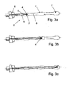
- Fig. 3a-c
- Prinzipskizzen einer erfindungsgemäßen Sensoreinheit in drei Bestückungsvarianten gemäß einer Variante des Ausführungsbeispiels.
- Zur Regelung eines Verdampfers 1 einer Kraftfahrzeug-Klimaanlage ist in Luftströmungsrichtung gesehen hinter dem Verdampfer 1 eine Sensoreinheit 2 für die Messung der Temperatur der den Verdampfer 1 durchströmenden Luft angeordnet, wobei die Messstelle 3 in dem den Verdampfer 1 durchströmenden Luftstrom an dem bei Betrieb der Klimaanlage kältesten Punkt angeordnet ist. Diese Anordnung hat den Vorteil, dass damit einer Vereisung des Verdampfers besonders effektiv vorgebeugt werden kann. Im Falle einer Verwendung der Sensoreinheit 2 bei einem Heizkörper kann neben der Anordnung am kältesten Punkt auch eine Anordnung am heißesten Punkt bzw. an einem Punkt mit einer Durchschnittstemperatur von Vorteil sein.
- Wesentlicher Bestandteil der Sensoreinheit 2 ist ein als Sensor dienendes NTC-Element 4 (NTC = negative temperature coefficient), welches eine Kennlinie mit negativem Temperaturkoeffizienten aufweist. Das NTC-Element 4 ist auf an sich bekannte Weise mit einem Kabel 5 verlötet und in ein Gehäuse 6 aus einem nicht brennbaren Kunststoff eingespritzt. Das Gehäuse 6 bildet hierbei sowohl einen Schutz für das NTC-Element 4 samt Kabel 5 als auch einen Schutz für die elektrische Kontaktierung des Kabels 5 vor Korrosion etc., wobei das Gehäuse 6 im entsprechenden Bereich als Teil eines Steckers ausgebildet ist. Femer dient das Gehäuse 6 als eine Halterung für das NTC-Element 4 samt Kabel 5.
- Das Gehäuse 6 ist L-förmig ausgebildet, wobei der kurze Schenkel des L der elektrischen Kontaktierung und Befestigung und der lange Schenkel der Anordnung und Positionierung des NTC-Elements 4 im Luftstrom dient.
- Um die Sensoreinheit 2 auf möglichst einfache Weise und kostengünstig möglichst universell einsetzbar zu machen, ist vorliegend das Gehäuse 6 mit drei im langen Schenkel des Gehäuses 6 ausgebildeten Aufnahmen 7 versehen, wobei alle drei Aufnahmen 7 das NTC-Element 4 aufnehmen können. Die Aufnahmen 7 sind jeweils durch Materialaussparungen gebildet, so dass das NTC-Element 4 in das Innere einer fensterartigen Öffnung ragt (vgl. Fig. 1a). Die Öffnung ist so groß, dass ausreichend Luft am NTC-Element 4 vorbeiströmen kann und die Messung nicht verfälscht wird.
- Die abschließende Positionierung des NTC-Elements 4 in der jeweiligen Aufnahme 7 erfolgt in Abhängigkeit der Messstelle und der hiermit in Zusammenhang stehenden erforderlichen Länge der Sensoreinheit 2. Fig. 1a zeigt die Anordnung des NTC-Elements 4 in der Aufnahme 7, die am nächsten zum Stecker ist, Fig. 1b die Anordnung in der Aufnahme 7, die mittig im langen Schenkel ausgebildet ist, und Fig. 1c die Anordnung in der am Ende des langen Schenkels ausgebildeten Aufnahme.
- Zur Vereinfachung der exakten Positionierung des NTC-Elements 4 in der gewünschten Aufnahme sind Kabel 5 mit drei unterschiedlichen Längen vorgesehen, die jeweils eine exakte Positionierung in der gewünschten Aufnahme 7 ermöglichen.
- Gemäß der in den Figuren 3a bis 3c dargestellten Variante ist das Gehäuse 6 langgestreckt, d.h. nicht L-förmig, und in der Nähe des Steckers mit einer als Anlagefläche dienenden Schräge 8 versehen ausgebildet, welche der besseren Fixierbarkeit und flexibleren Positionierung des NTC-Elements 4 im Luftkanal dient. Vorliegend ist das Gehäuse 6 um das NTC-Element 4 und das Kabel 5 gespritzt. Ansonsten entspricht die Ausgestaltung der des ersten Ausführungsbeispiels, d.h. es sind wiederum drei mögliche Aufnahmen für das eine NTC-Element 4 vorgesehen, das an einem Kabel angelötet ist. Entsprechend sind wiederum drei unterschiedliche Kabellängen vorgesehen.
- Gemäß einer alternativen Ausführungsform ist das Gehäuse getrennt vom NTC-Element und Kabel ausgebildet, wobei das Gehäuse zweiteilig ausgebildet ist und nach dem Einlegen des NTC-Elements samt Kabel geschlossen wird. Hierbei sind die beiden Gehäusehälften, wobei die Gehäusehätften nicht notwendigerweise mittig geteilt sein müssen, fluiddicht miteinander verbunden, so dass ein elektrischer Kurzschluss o.ä. sicher vermieden werden kann. Das Verschließen kann beispielsweise mittels mehrerer Clipsverbindungen, Schrauben oder Verkleben erfolgen.
Claims (12)
- Sensoreinheit, insbesondere für einen Verdampfer (1) eines Kraftfahr zeugs, mit mindestens einem in einem Gehäuse (6) angeordneten Sensor-Element (4), das über ein Kabel (5) elektrisch kontaktiert ist und der Temperaturmessung dient, dadurch gekennzeichnet, dass das Gehäuse (6) mehrere voneinander beabstandete Aufnahmen (7) für das Sensor-Element (4) aufweist.
- Sensoreinheit nach Anspruch 1, dadurch gekennzeichnet, dass wenigstens ein Sensor-Element (4) ein Temperatur-Sensor-Element ist, insbesondere ein NTC-Element und/oder ein PTC-Element.
- Sensoreinheit nach Anspruch 1 oder 2, dadurch gekennzeichnet, dass das Gehäuse (6) langgestreckt ausgebildet ist, wobei die Aufnahmen (7) über die Länge des Gehäuses (6) verteilt angeordnet sind.
- Sensoreinheit nach einem der vorangehenden Ansprüche, dadurch gekennzeichnet, dass zwei bis fünf, insbesondere drei oder vier, Aufnahmen (7) vorgesehen sind.
- Sensoreinheit nach einem der vorhergehenden Ansprüche, dadurch gekennzeichnet, dass die Aufnahmen (7) in einer Reihe zueinander vorgesehen sind, wobei nur in genau einer der Aufnahmen (7) ein Sensor-Element (4) angeordnet ist.
- Sensoreinheit nach einem der vorhergehenden Ansprüche, dadurch gekennzeichnet, dass die Kabellänge an die Länge des Gehäuses (6) bis zur Aufnahme (7) angepasst ist.
- Sensoreinheit nach einem der vorhergehenden Ansprüche, dadurch gekennzeichnet, dass das Gehäuse (6) im Bereich der Befestigung der Sensoreinheit (2) eine Schräge (8) aufweist.
- Sensoreinheit nach einem der vorhergehenden Ansprüche, dadurch gekennzeichnet, dass das Gehäuse (6) einen Teil eines Steckkontakts bildet und die elektrischen Anschlüsse schützt.
- Sensoreinheit nach einem der vorhergehenden Ansprüche, dadurch gekennzeichnet, dass das Gehäuse (6) um das Kabel (5) samt Sensor-Element (4) spritzgegossen ist.
- Sensoreinheit nach einem der vorhergehenden Ansprüche, dadurch gekennzeichnet, dass das Gehäuse (6) durch einen nicht brennbaren Kunststoff gebildet ist.
- Sensoreinheit nach einem der vorhergehenden Ansprüche, dadurch gekennzeichnet, dass das Gehäuse (6) L-förmig ausgebildet ist.
- Verwendung einer Sensoreinheit (2) nach einem der vorhergehenden Ansprüche als Teil einer Überwachungs- und Regelungseinrichtung eines Verdampfers (1) und/oder eines Heizkörpers einer Kraftfahrzeug-Klimaanlage.
Applications Claiming Priority (1)
| Application Number | Priority Date | Filing Date | Title |
|---|---|---|---|
| DE200510026189 DE102005026189A1 (de) | 2005-06-06 | 2005-06-06 | Sensoreinheit, insbesondere für einen Verdampfer eines Kraftfahrzeugs |
Publications (2)
| Publication Number | Publication Date |
|---|---|
| EP1731888A1 true EP1731888A1 (de) | 2006-12-13 |
| EP1731888B1 EP1731888B1 (de) | 2008-11-05 |
Family
ID=37402030
Family Applications (1)
| Application Number | Title | Priority Date | Filing Date |
|---|---|---|---|
| EP20060011431 Expired - Lifetime EP1731888B1 (de) | 2005-06-06 | 2006-06-01 | Sensoreinheit, insbesondere für einen Verdampfer eines Kraftfahrzeugs |
Country Status (2)
| Country | Link |
|---|---|
| EP (1) | EP1731888B1 (de) |
| DE (2) | DE102005026189A1 (de) |
Citations (4)
| Publication number | Priority date | Publication date | Assignee | Title |
|---|---|---|---|---|
| US5560392A (en) * | 1995-03-29 | 1996-10-01 | Postberg Anne Karin M | Valve for a measuring device |
| JPH08261845A (ja) * | 1995-03-22 | 1996-10-11 | Nippondenso Co Ltd | サーミスタ式温度検出器 |
| EP1037028A1 (de) * | 1999-03-09 | 2000-09-20 | Mannesmann VDO Aktiengesellschaft | Sensor zur kombinierten Temperatur- und Füllstandserfassung |
| US20020122459A1 (en) * | 2000-12-27 | 2002-09-05 | Mcfarland Dawn Key | Passively cooled high temperature capable probe housing |
Family Cites Families (4)
| Publication number | Priority date | Publication date | Assignee | Title |
|---|---|---|---|---|
| US4348870A (en) * | 1981-05-01 | 1982-09-14 | Essex Group, Inc. | Temperature probe for air conditioning device |
| DE19544880B4 (de) * | 1995-12-01 | 2005-01-05 | Alstom | Temperatursonde |
| DE29823855U1 (de) * | 1998-07-14 | 1999-12-30 | Hartmann & Braun GmbH & Co. KG, 65760 Eschborn | Vorrichtung zur Einführung eines Vergleichsthermometers in einen in Betrieb befindlichen Behälter |
| DE29817221U1 (de) * | 1998-09-29 | 2000-02-10 | Taprogge GmbH, 58300 Wetter | Meßrohr, insbesondere für Wärmetauscher, mit mindestens einem Thermoelement |
-
2005
- 2005-06-06 DE DE200510026189 patent/DE102005026189A1/de not_active Withdrawn
-
2006
- 2006-06-01 EP EP20060011431 patent/EP1731888B1/de not_active Expired - Lifetime
- 2006-06-01 DE DE200650001977 patent/DE502006001977D1/de not_active Expired - Lifetime
Patent Citations (4)
| Publication number | Priority date | Publication date | Assignee | Title |
|---|---|---|---|---|
| JPH08261845A (ja) * | 1995-03-22 | 1996-10-11 | Nippondenso Co Ltd | サーミスタ式温度検出器 |
| US5560392A (en) * | 1995-03-29 | 1996-10-01 | Postberg Anne Karin M | Valve for a measuring device |
| EP1037028A1 (de) * | 1999-03-09 | 2000-09-20 | Mannesmann VDO Aktiengesellschaft | Sensor zur kombinierten Temperatur- und Füllstandserfassung |
| US20020122459A1 (en) * | 2000-12-27 | 2002-09-05 | Mcfarland Dawn Key | Passively cooled high temperature capable probe housing |
Also Published As
| Publication number | Publication date |
|---|---|
| DE102005026189A1 (de) | 2006-12-07 |
| DE502006001977D1 (de) | 2008-12-18 |
| EP1731888B1 (de) | 2008-11-05 |
Similar Documents
| Publication | Publication Date | Title |
|---|---|---|
| EP2434195B1 (de) | Verfahren zur Temperaturmessung in einem Fahrzeug | |
| DE3210260C1 (de) | Behaelter fuer Betriebsmittel in Kraftfahrzeugen | |
| DE102007011673A1 (de) | Kühlmittelregler und Verfahren zu dessen Herstellung | |
| EP3198250A1 (de) | Steckergehäuse für eine sensorvorrichtung und steckermodul | |
| EP3096587B1 (de) | Elektrische heizvorrichtung | |
| DE4108789C2 (de) | Temperatursensor | |
| DE102006022620A1 (de) | Temperatursensor | |
| DE102005036430B4 (de) | Tankheizung | |
| DE112018007944T5 (de) | Bordkameravorrichtung | |
| DE102009048940B3 (de) | Heizkostenverteiler | |
| EP1731888B1 (de) | Sensoreinheit, insbesondere für einen Verdampfer eines Kraftfahrzeugs | |
| DE19902431B4 (de) | Zwischenstück mit einem Anschluß von Waschflüssigkeitsleitungen einer Scheibenreinigungsanlage | |
| DE102005039764B4 (de) | Verfahren zur Herstellung einer thermischen Kopplung | |
| DE102020134912A1 (de) | Sensoranordnung für ein Fluid, Fluidtank und Verwendung der Sensoranordnung | |
| EP1464934A1 (de) | Vorrichtung zur Bestimmung der Temperatur eines strömenden Mediums in einer Rohr- oder Schlauchleitung | |
| EP2196076B1 (de) | Datenübertragungsmodul | |
| DE3005075C2 (de) | Vorrichtung zum Erfassen einer Oberflächentemperatur eines Wärmetauschers | |
| DE19922668B4 (de) | Heizkörper für Kraftfahrzeuge | |
| DE102004062908A1 (de) | Sensor und Verfahren zum Herstellen eines Sensors | |
| EP1741888A1 (de) | Vorratsbehälter eines Kraftfahrzeugs | |
| EP3096095B1 (de) | Elektrische heizvorrichtung | |
| DE19724734A1 (de) | Elektrische Heizeinrichtung, insbesondere für ein Kraftfahrzeug | |
| DE102007005130A1 (de) | Düseneinrichtung zur Reinigung einer Scheibe | |
| DE102006061098B4 (de) | Kältegerät | |
| DE19623632A1 (de) | Elektrischer Anschlußkasten |
Legal Events
| Date | Code | Title | Description |
|---|---|---|---|
| PUAI | Public reference made under article 153(3) epc to a published international application that has entered the european phase |
Free format text: ORIGINAL CODE: 0009012 |
|
| AK | Designated contracting states |
Kind code of ref document: A1 Designated state(s): AT BE BG CH CY CZ DE DK EE ES FI FR GB GR HU IE IS IT LI LT LU LV MC NL PL PT RO SE SI SK TR |
|
| AX | Request for extension of the european patent |
Extension state: AL BA HR MK YU |
|
| 17P | Request for examination filed |
Effective date: 20070613 |
|
| 17Q | First examination report despatched |
Effective date: 20070712 |
|
| AKX | Designation fees paid |
Designated state(s): DE ES FR IT NL |
|
| GRAP | Despatch of communication of intention to grant a patent |
Free format text: ORIGINAL CODE: EPIDOSNIGR1 |
|
| GRAS | Grant fee paid |
Free format text: ORIGINAL CODE: EPIDOSNIGR3 |
|
| GRAA | (expected) grant |
Free format text: ORIGINAL CODE: 0009210 |
|
| AK | Designated contracting states |
Kind code of ref document: B1 Designated state(s): DE ES FR IT NL |
|
| REF | Corresponds to: |
Ref document number: 502006001977 Country of ref document: DE Date of ref document: 20081218 Kind code of ref document: P |
|
| NLV1 | Nl: lapsed or annulled due to failure to fulfill the requirements of art. 29p and 29m of the patents act | ||
| PG25 | Lapsed in a contracting state [announced via postgrant information from national office to epo] |
Ref country code: ES Free format text: LAPSE BECAUSE OF FAILURE TO SUBMIT A TRANSLATION OF THE DESCRIPTION OR TO PAY THE FEE WITHIN THE PRESCRIBED TIME-LIMIT Effective date: 20090216 |
|
| PG25 | Lapsed in a contracting state [announced via postgrant information from national office to epo] |
Ref country code: NL Free format text: LAPSE BECAUSE OF FAILURE TO SUBMIT A TRANSLATION OF THE DESCRIPTION OR TO PAY THE FEE WITHIN THE PRESCRIBED TIME-LIMIT Effective date: 20081105 |
|
| PLBE | No opposition filed within time limit |
Free format text: ORIGINAL CODE: 0009261 |
|
| STAA | Information on the status of an ep patent application or granted ep patent |
Free format text: STATUS: NO OPPOSITION FILED WITHIN TIME LIMIT |
|
| 26N | No opposition filed |
Effective date: 20090806 |
|
| PGFP | Annual fee paid to national office [announced via postgrant information from national office to epo] |
Ref country code: FR Payment date: 20100722 Year of fee payment: 5 |
|
| PG25 | Lapsed in a contracting state [announced via postgrant information from national office to epo] |
Ref country code: IT Free format text: LAPSE BECAUSE OF FAILURE TO SUBMIT A TRANSLATION OF THE DESCRIPTION OR TO PAY THE FEE WITHIN THE PRESCRIBED TIME-LIMIT Effective date: 20081105 |
|
| REG | Reference to a national code |
Ref country code: FR Ref legal event code: ST Effective date: 20120229 |
|
| PG25 | Lapsed in a contracting state [announced via postgrant information from national office to epo] |
Ref country code: FR Free format text: LAPSE BECAUSE OF NON-PAYMENT OF DUE FEES Effective date: 20110630 |
|
| PGFP | Annual fee paid to national office [announced via postgrant information from national office to epo] |
Ref country code: DE Payment date: 20120711 Year of fee payment: 7 |
|
| REG | Reference to a national code |
Ref country code: DE Ref legal event code: R119 Ref document number: 502006001977 Country of ref document: DE Effective date: 20140101 |
|
| PG25 | Lapsed in a contracting state [announced via postgrant information from national office to epo] |
Ref country code: DE Free format text: LAPSE BECAUSE OF NON-PAYMENT OF DUE FEES Effective date: 20140101 |