EP1731865A1 - Oil-cooler-equipped radiator - Google Patents
Oil-cooler-equipped radiator Download PDFInfo
- Publication number
- EP1731865A1 EP1731865A1 EP05291205A EP05291205A EP1731865A1 EP 1731865 A1 EP1731865 A1 EP 1731865A1 EP 05291205 A EP05291205 A EP 05291205A EP 05291205 A EP05291205 A EP 05291205A EP 1731865 A1 EP1731865 A1 EP 1731865A1
- Authority
- EP
- European Patent Office
- Prior art keywords
- tank
- oil
- cooler
- portions
- heat exchanger
- Prior art date
- Legal status (The legal status is an assumption and is not a legal conclusion. Google has not performed a legal analysis and makes no representation as to the accuracy of the status listed.)
- Withdrawn
Links
- 238000005219 brazing Methods 0.000 claims description 10
- 230000002093 peripheral effect Effects 0.000 description 5
- 229910052782 aluminium Inorganic materials 0.000 description 4
- XAGFODPZIPBFFR-UHFFFAOYSA-N aluminium Chemical compound [Al] XAGFODPZIPBFFR-UHFFFAOYSA-N 0.000 description 2
- 210000000078 claw Anatomy 0.000 description 2
- 238000010438 heat treatment Methods 0.000 description 2
- HCHKCACWOHOZIP-UHFFFAOYSA-N Zinc Chemical compound [Zn] HCHKCACWOHOZIP-UHFFFAOYSA-N 0.000 description 1
- 230000005540 biological transmission Effects 0.000 description 1
- 238000001816 cooling Methods 0.000 description 1
- 239000000498 cooling water Substances 0.000 description 1
- 238000005260 corrosion Methods 0.000 description 1
- 230000007797 corrosion Effects 0.000 description 1
- 230000008878 coupling Effects 0.000 description 1
- 238000010168 coupling process Methods 0.000 description 1
- 238000005859 coupling reaction Methods 0.000 description 1
- 238000009792 diffusion process Methods 0.000 description 1
- 230000002349 favourable effect Effects 0.000 description 1
- 239000000463 material Substances 0.000 description 1
- 238000000034 method Methods 0.000 description 1
- 230000004048 modification Effects 0.000 description 1
- 238000012986 modification Methods 0.000 description 1
- 230000002787 reinforcement Effects 0.000 description 1
- 239000011701 zinc Substances 0.000 description 1
- 229910052725 zinc Inorganic materials 0.000 description 1
Images






Classifications
-
- F—MECHANICAL ENGINEERING; LIGHTING; HEATING; WEAPONS; BLASTING
- F28—HEAT EXCHANGE IN GENERAL
- F28F—DETAILS OF HEAT-EXCHANGE AND HEAT-TRANSFER APPARATUS, OF GENERAL APPLICATION
- F28F9/00—Casings; Header boxes; Auxiliary supports for elements; Auxiliary members within casings
- F28F9/02—Header boxes; End plates
- F28F9/0246—Arrangements for connecting header boxes with flow lines
-
- F—MECHANICAL ENGINEERING; LIGHTING; HEATING; WEAPONS; BLASTING
- F28—HEAT EXCHANGE IN GENERAL
- F28F—DETAILS OF HEAT-EXCHANGE AND HEAT-TRANSFER APPARATUS, OF GENERAL APPLICATION
- F28F9/00—Casings; Header boxes; Auxiliary supports for elements; Auxiliary members within casings
- F28F9/02—Header boxes; End plates
- F28F9/0234—Header boxes; End plates having a second heat exchanger disposed there within, e.g. oil cooler
-
- F—MECHANICAL ENGINEERING; LIGHTING; HEATING; WEAPONS; BLASTING
- F28—HEAT EXCHANGE IN GENERAL
- F28F—DETAILS OF HEAT-EXCHANGE AND HEAT-TRANSFER APPARATUS, OF GENERAL APPLICATION
- F28F9/00—Casings; Header boxes; Auxiliary supports for elements; Auxiliary members within casings
- F28F9/02—Header boxes; End plates
- F28F9/0246—Arrangements for connecting header boxes with flow lines
- F28F9/0248—Arrangements for sealing connectors to header boxes
Definitions
- the present invention relates to an oil-cooler-equipped radiator which is brazed while an oil cooler is accommodated in a tank of the radiator for a motor vehicle, and the like.
- an all-aluminum radiator in which a tank and core portions of a radiator are formed of aluminum has been developed.
- brazing of a tank and an oil cooler is performed while the oil cooler is accommodated in the tank.
- the present invention has been made in view of the above-described problems, and an object thereof is to provide an oil-cooler-equipped radiator in which a tank and a pipe connector are heated up quickly so as to assure brazing of the both.
- An oil-cooler-equipped radiator has: an oil cooler which includes a heat exchanger having a plurality of element units stacked in a state communicating with each other, pipe connectors coupled to the heat exchanger in a state communicating with spaces formed respectively at both end portions in the longitudinal direction of the heat exchanger, and a pair of connecting pipes communicating with the spaces; and a radiator which includes a tank having connecting pipe attaching holes formed therein and connected to the pair of connecting pipes via cylindrical portions of the pipe connectors respectively, wherein the oil cooler is fixed with the tank by brazing and accommodated therein, and the cylindrical portions of the pipe connectors being fixed respectively to rings provided on the outside of the tank at the connecting pipe attaching holes, and joint portions of the pipe connectors and the rings are formed to be exposed to the outside of the tank.
- the pipe connectors are provided with heat conduction portions respectively, and the heat conduction portions being brazed on the inside of the tank in a tightly attached state.
- the heat exchanger is heated up via the heat conduction portion, so that the heat conduction portion of the pipe connector and the inside of the tank can be favorably brazed, and moreover the entire oil cooler including the pipe connector can be smoothly heated up to be brazed.
- the oil-cooler-equipped radiator includes a pair of seat plates 2a and 2b provided at an upper side of a radiator 100 and at a lower side of the radiator 100 with upper and lower tanks 1a and 1b, respectively; tubes 3 and corrugated fins 4 alternately disposed between the seat plates 2a and 2b; and reinforcements 5a and 5b for connecting both end portions of the seat plates 2a and 2b at their both sides so as to reinforce them.
- the oil cooler 6 has a heat exchanger 8 including a plurality of element units 7 stacked in a state communicating with each other, pipe connectors 13 coupled via clamps 12 to the heat exchanger 8 in a state communicating with spaces O formed respectively at both end portions of the heat exchanger 8, and a pair of connecting pipes P1 and P2 communicating respectively with the spaces O from two connecting pipe attaching holes 16 and 16 formed on the lower tank 1b via cylindrical portions 13a of the pipe connectors 13.
- brazing material is coated on at least one side of the contact parts.
- a pair of shells 7b and 7c each having a periphery being raised so as to form a dish shape and having cylindrical portions 7a formed by burring on both end portions thereof is press fitted or caulked together with a corrugated inner fin 7d being interposed therebetween, thereby forming an element unit 7.
- patch plates PT are press fitted or caulked via sheets 9a respectively.
- the clamp 12 and a pipe connector 13, which will be described later, are fixed via a sheet 9b on each of the cylindrical portions 7a and 7a of an outermost element unit 11 that is located at an opposite outermost position of the element units 7 in the stacking direction thereof.
- the clamp 12 has a cylindrical portion 12a is formed by burring at the center portion of the clamp 12 and a peripheral edge portion 12b that is raised so as to form a dish shape having three claw portions 12c at equivalent intervals.
- a cylindrical portion 13a is formed by burring.
- a heat conduction portion 13b which will be described in detail later, is formed, and a peripheral edge portion 13c thereof is raised downward in the view to form a dish shape.
- the tank 1b is constituted of a first divided part 14 in a lid-like shape and a second divided part 15 having a U-shaped cross section, and on the first divided part 14, connecting pipe attaching holes 16 are formed respectively at positions corresponding to the connecting pipes P1 and P2, which will be described in detail later.
- the diameter of the connecting pipe attaching holes 16 is formed to be slightly larger than the outside diameter of the cylindrical part 13a of the pipe connector 13.
- the cylindrical portion 13a of the pipe connector 13 is projected outward through the connecting pipe attaching hole 16, and the heat conduction portion 13b is tightly attached on a sidewall inner side 17 of the first divided part 14.
- the cylindrical portion 13a is caulked on an annular ring 19 placed on a sidewall outer side 18 of the divided part 14, and thereafter the first divided part 14 and the second divided part 15 are engaged with each other, thereby accommodating the oil cooler 6 in the tank 1b.
- the sidewall inner side 17 corresponds to an inside of a tank of the present invention
- the sidewall outer side 18 corresponds to an outside of a tank of the present invention.
- the pipe connector 13 is jointed to the ring 19 at a joint portion 20 to be fixed thereon, and the joint portion 20 is exposed to the outside of the lower tank 1b.
- a predetermined gap is formed between the cylindrical portion 13a and the connecting pipe attaching hole 16, so that the position of the oil cooler can be adjusted in the range of W1 with respect to the tank 1b. Therefore, an error of the oil cooler 6 caused by assembling accuracy can be tolerated.
- the inside of the ring 19 in this embodiment is formed in a slope shape as shown in FIG. 11, and accordingly this structure enables the tip of the cylindrical portion 13a to be easily caulked.
- the oil-cooler-equipped radiator that is thus temporarily assembled is heat treated in a not-shown furnace with not-shown patches being engaged with both end portions of the tank 1b, while the oil cooler 6 is accommodated therein.
- respective portions of the radiator 100 as well as contact parts of respective portions of the tank 1b and the oil cooler 6 are brazed, resulting in a cooling circuit in which oil for an engine or an automatic transmission (AT) is flown from the connecting pipe P1 through the element units 7 of the heat exchanger 8 in the longitudinal direction so as to exchange the heat of oil with cooling water in the tank 1b, and then the oil is discharged from the connecting pipe P2.
- AT automatic transmission
- the heat exchanger 8 is heated up via the heat conduction portion 13b and the clamp 12, so that the heat conduction portion 13b of the pipe connector 13 and the inside of the tank can be favorably brazed, and moreover the entire oil cooler 6 can be smoothly heated up to be brazed.
- the position adjustment range W1 of the oil cooler 6 can be set in a discretionary range by appropriately changing the diameters of the connecting pipe attaching hole 16 and ring 19 and the shape of the cylindrical portion 13a.
- the temporarily assembled oil cooler 6 may be brazed alone in a preceding step, and in the following step, it may be accommodated in the tank 1b of the temporarily assembled radiator 100 to thereby braze the radiator 100 and the oil cooler 6 together.
Landscapes
- Engineering & Computer Science (AREA)
- Physics & Mathematics (AREA)
- Thermal Sciences (AREA)
- Mechanical Engineering (AREA)
- General Engineering & Computer Science (AREA)
- Details Of Heat-Exchange And Heat-Transfer (AREA)
Abstract
Description
- The present invention relates to an oil-cooler-equipped radiator which is brazed while an oil cooler is accommodated in a tank of the radiator for a motor vehicle, and the like.
- Conventionally, techniques about an oil-cooler-equipped radiator in which an oil cooler is accommodated in a tank of the radiator have been known, which are disclosed in
Japanese Patent Application Laid-open Nos. 2001-153586 Hei 10-73393 Hei 11-142089 - Also, an all-aluminum radiator in which a tank and core portions of a radiator are formed of aluminum has been developed. In this type of radiator, brazing of a tank and an oil cooler is performed while the oil cooler is accommodated in the tank.
- However, in the conventional oil-cooler-equipped radiator, for example, when the all-aluminum radiator is brazed, a pipe connector, which is a fixing portion of the oil cooler on the tank, is not smoothly heated up, which causes a problem of generating a brazing failure.
- If a time period of brazing is extended, zinc diffusion in a radiator tube may proceed and degrade the corrosion resistance of the radiator tube, which is not favorable.
- The present invention has been made in view of the above-described problems, and an object thereof is to provide an oil-cooler-equipped radiator in which a tank and a pipe connector are heated up quickly so as to assure brazing of the both.
- An oil-cooler-equipped radiator according to the present invention has: an oil cooler which includes a heat exchanger having a plurality of element units stacked in a state communicating with each other, pipe connectors coupled to the heat exchanger in a state communicating with spaces formed respectively at both end portions in the longitudinal direction of the heat exchanger, and a pair of connecting pipes communicating with the spaces; and a radiator which includes a tank having connecting pipe attaching holes formed therein and connected to the pair of connecting pipes via cylindrical portions of the pipe connectors respectively, wherein the oil cooler is fixed with the tank by brazing and accommodated therein, and the cylindrical portions of the pipe connectors being fixed respectively to rings provided on the outside of the tank at the connecting pipe attaching holes, and joint portions of the pipe connectors and the rings are formed to be exposed to the outside of the tank.
- In the above-described oil-cooler-equipped radiator, when the tank and the oil cooler are brazed, the cylindrical portions of the pipe connectors are fixed to the rings provided on the outside of the tank at the connecting pipe attaching holes, so that the rings are heated up quickly. Moreover, the joint portions of the rings and the pipe connectors are formed to be exposed to the outside, so that the entire pipe connectors are heated up quickly. Therefore, the both can be surely brazed.
- Preferably, the pipe connectors are provided with heat conduction portions respectively, and the heat conduction portions being brazed on the inside of the tank in a tightly attached state.
- Therefore, along with the heating up of the tank, the heat exchanger is heated up via the heat conduction portion, so that the heat conduction portion of the pipe connector and the inside of the tank can be favorably brazed, and moreover the entire oil cooler including the pipe connector can be smoothly heated up to be brazed.
- The objects, features and advantages of the present invention will become apparent as the description proceeds when taken in conjunction with the accompanying drawings, in which:
- FIG. 1 is an overall view showing an oil-cooler-equipped radiator according to an embodiment of the present invention;
- FIG. 2 is an enlarged cross sectional view taken along the line S2-S2 in FIG. 1;
- FIG. 3 is an enlarged cross sectional view taken along the line S3-S3 in FIG. 1;
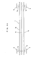
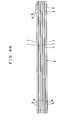
- FIGS. 4A and 4B are enlarged views illustrating assembly of a heat exchanger before assembled and after assembled, respectively;
- FIGS. 5A and 5B are enlarged views illustrating assembly of the heat exchanger, patches, clamps, and pipe connectors before assembled and after assembled, respectively;
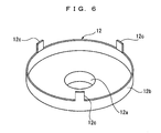
52 - FIG. 6 is an enlarged perspective view of the clamp;
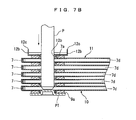
- FIGS. 7A and 7B are enlarged views illustrating fixation of the heat exchanger and the clamp before fixed and after fixed, respectively;
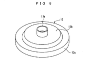
- FIG. 8 is an enlarged perspective view of the pipe connector;
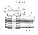
- FIGS. 9A and 9B are enlarged views illustrating fixation of the pipe connector and the clamp before fixed and after fixed, respectively;
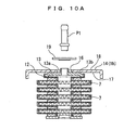
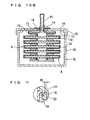
- FIGS. 10A and 10B are enlarged views illustrating fixation of the oil cooler and a tank before fixed and after fixed, respectively; and
- FIG. 11 is an enlarged cross sectional view of contact part of a connecting pipe and a tank, indicated by a circle CA in FIG. 10B.
- Hereinafter, an embodiment of an oil-cooler-equipped radiator according to the present invention will be described with accompanying drawings.
- As shown in FIG. 1, the oil-cooler-equipped radiator according to the embodiment includes a pair of
seat plates radiator 100 and at a lower side of theradiator 100 with upper andlower tanks fins 4 alternately disposed between theseat plates reinforcements seat plates - An
oil cooler 6, which will be described in detail later, is accommodated in thelower tank 1b, and all the components including theoil cooler 6 and thelower tank 1b are made of aluminum. - As shown in FIGS. 2 and 3, the
oil cooler 6 according to the embodiment has aheat exchanger 8 including a plurality ofelement units 7 stacked in a state communicating with each other,pipe connectors 13 coupled viaclamps 12 to theheat exchanger 8 in a state communicating with spaces O formed respectively at both end portions of theheat exchanger 8, and a pair of connecting pipes P1 and P2 communicating respectively with the spaces O from two connectingpipe attaching holes lower tank 1b viacylindrical portions 13a of thepipe connectors 13. - Also, at each contact part between the components of the
tank 1b and theoil cooler 6, a brazing material (brazing sheet) is coated on at least one side of the contact parts. - To temporarily assemble such an oil-cooler-equipped radiator, at first, as shown in FIG. 4A, a pair of
shells cylindrical portions 7a formed by burring on both end portions thereof is press fitted or caulked together with a corrugatedinner fin 7d being interposed therebetween, thereby forming anelement unit 7. - Subsequently, as shown in FIG. 4B, a plurality of
element units 7, five layer units in this embodiment, are stacked withcylindrical sheets 9 being interposed therebetween, thereby forming theheat exchanger 8. - Next, as shown in FIGS. 5A and 5B, on the
cylindrical portions outermost element unit 10 that is located at an outermost position of theelement units 7 in the stacking direction thereof, patch plates PT are press fitted or caulked viasheets 9a respectively. - On the other hand, the
clamp 12 and apipe connector 13, which will be described later, are fixed via asheet 9b on each of thecylindrical portions outermost element unit 11 that is located at an opposite outermost position of theelement units 7 in the stacking direction thereof. - Specifically, as shown in FIG. 6, the
clamp 12 has acylindrical portion 12a is formed by burring at the center portion of theclamp 12 and aperipheral edge portion 12b that is raised so as to form a dish shape having threeclaw portions 12c at equivalent intervals. - Then, as shown in FIGS. 7A and 7B, the
cylindrical portion 12a of theclamp 12 is overlapped on thecylindrical portion 7a of theoutermost element unit 11, and in this state, a jig such as a column-shaped punch P is press fitted into the space O so as to caulk them, thereby fixing theheat exchanger 8 and theclamp 12. - At this time, all
cylindrical portions 7a of therespective element units 7 including theoutermost element units cylindrical portion 12a. - Next, the
clamp 12 and apipe connector 13 are fixed with each other. - Specifically, as shown in FIG. 8, at the center portion of the
pipe connector 13, acylindrical portion 13a is formed by burring. On a center side portion thereof, aheat conduction portion 13b, which will be described in detail later, is formed, and aperipheral edge portion 13c thereof is raised downward in the view to form a dish shape. - Then, as shown in FIGS. 9A and 9B, the
peripheral edge portions 12b of theclamp 12 and theperipheral edge portion 13c of thepipe connector 13 are overlapped with each other, and thereafter theclaw portions 12c of theclamp 12 are caulked on theperipheral edge portion 13c of thepipe connector 13, thereby fixing theclamp 12 and thepipe connector 13 with each other. - Subsequently, the
oil cooler 6, made by coupling theheat exchanger 8, theclamp 12, and thepipe connector 13 with each other, is accommodated in thelower tank 1b. - Specifically, the
tank 1b is constituted of a first dividedpart 14 in a lid-like shape and a second dividedpart 15 having a U-shaped cross section, and on the first dividedpart 14, connectingpipe attaching holes 16 are formed respectively at positions corresponding to the connecting pipes P1 and P2, which will be described in detail later. - Further, the diameter of the connecting
pipe attaching holes 16 is formed to be slightly larger than the outside diameter of thecylindrical part 13a of thepipe connector 13. - Moreover, as shown in FIGS. 10A and 10B, the
cylindrical portion 13a of thepipe connector 13 is projected outward through the connectingpipe attaching hole 16, and theheat conduction portion 13b is tightly attached on a sidewallinner side 17 of the first dividedpart 14. Thecylindrical portion 13a is caulked on anannular ring 19 placed on a sidewallouter side 18 of the dividedpart 14, and thereafter the first dividedpart 14 and the second dividedpart 15 are engaged with each other, thereby accommodating theoil cooler 6 in thetank 1b. The sidewallinner side 17 corresponds to an inside of a tank of the present invention, and the sidewallouter side 18 corresponds to an outside of a tank of the present invention. - At this time, the
pipe connector 13 is jointed to thering 19 at ajoint portion 20 to be fixed thereon, and thejoint portion 20 is exposed to the outside of thelower tank 1b. - Further, as shown in FIG. 11, a predetermined gap is formed between the
cylindrical portion 13a and the connectingpipe attaching hole 16, so that the position of the oil cooler can be adjusted in the range of W1 with respect to thetank 1b. Therefore, an error of theoil cooler 6 caused by assembling accuracy can be tolerated. - Incidentally, for the caulking of the tip of the
cylindrical portion 13a and thering 19, a jig such as the above-described punch is used. - Also, the inside of the
ring 19 in this embodiment is formed in a slope shape as shown in FIG. 11, and accordingly this structure enables the tip of thecylindrical portion 13a to be easily caulked. - Finally, the connecting pipe P1 is press fitted into the
cylindrical portion 13a of thepipe connector 13, thereby completing the temporary assembly of the oil-cooler-equipped radiator. - The oil-cooler-equipped radiator that is thus temporarily assembled is heat treated in a not-shown furnace with not-shown patches being engaged with both end portions of the
tank 1b, while theoil cooler 6 is accommodated therein. Thus, respective portions of theradiator 100 as well as contact parts of respective portions of thetank 1b and theoil cooler 6 are brazed, resulting in a cooling circuit in which oil for an engine or an automatic transmission (AT) is flown from the connecting pipe P1 through theelement units 7 of theheat exchanger 8 in the longitudinal direction so as to exchange the heat of oil with cooling water in thetank 1b, and then the oil is discharged from the connecting pipe P2. - When the brazing is carried out, the
rings 19 provided on the outside of the tank are heated up quickly, and in addition thejoint portions 20 of thepipe connectors 13 and therings 19 are formed to be exposed to the outside, so that theentire pipe connectors 13 are smoothly heated up. Therefore, both thetank 1b and thepipe connector 13 can be surely brazed. - Also, along with the heating up of the
tank 1b, theheat exchanger 8 is heated up via theheat conduction portion 13b and theclamp 12, so that theheat conduction portion 13b of thepipe connector 13 and the inside of the tank can be favorably brazed, and moreover theentire oil cooler 6 can be smoothly heated up to be brazed. - In the foregoing, the embodiment of the present invention has been described, but the specific configuration of the present invention is not limited to the above-described embodiment, and any design modification and so on without departing from the spirit of the present invention will be embraced in the present invention.
- For example, the position adjustment range W1 of the
oil cooler 6 can be set in a discretionary range by appropriately changing the diameters of the connectingpipe attaching hole 16 andring 19 and the shape of thecylindrical portion 13a. - Further, in this embodiment, the case of brazing the temporarily assembled
oil cooler 6 while it is temporarily accommodated in thetank 1b of the temporarily assembledradiator 100 is described. However, the temporarily assembled oil cooler may be brazed alone in a preceding step, and in the following step, it may be accommodated in thetank 1b of the temporarily assembledradiator 100 to thereby braze theradiator 100 and theoil cooler 6 together.
Claims (2)
- An oil-cooler-equipped radiator, comprising:an oil cooler (6) which includes a heat exchanger (8) having a plurality of element units (7) stacked in a state communicating with each other, pipe connectors (13) coupled to said heat exchanger (8) in a state communicating with spaces (O) formed respectively at both end portions in the longitudinal direction of said heat exchanger (8), and a pair of connecting pipes (P1, P2) communicating with the spaces (O); anda radiator (100) which includes a tank (1b) having connecting pipe attaching holes (16) formed therein and connected to said pair of connecting pipes (P1, P2) via cylindrical portions (13a) of said pipe connectors (13), respectively, characterized in thatsaid oil cooler (6) is fixed with said tank (1b) by brazing and accommodated therein, andthe cylindrical portions (13a) of said pipe connectors (13) being fixed respectively to rings (19) provided on the outside of said tank (1b) at the connecting pipe attaching holes (16), and joint portions (20) of the pipe connectors (13) and the rings (19) are formed to be exposed to the outside of said tank (1b).
- An oil-cooler-equipped radiator according to claim 1, characterized in that further
the pipe connectors (13) are provided with heat conduction portions (13b) respectively, and
said heat conduction portions (13b) being brazed on the inside of said tank (1b) in a tightly attached state.
Priority Applications (1)
| Application Number | Priority Date | Filing Date | Title |
|---|---|---|---|
| EP05291205A EP1731865A1 (en) | 2005-06-06 | 2005-06-06 | Oil-cooler-equipped radiator |
Applications Claiming Priority (1)
| Application Number | Priority Date | Filing Date | Title |
|---|---|---|---|
| EP05291205A EP1731865A1 (en) | 2005-06-06 | 2005-06-06 | Oil-cooler-equipped radiator |
Publications (1)
| Publication Number | Publication Date |
|---|---|
| EP1731865A1 true EP1731865A1 (en) | 2006-12-13 |
Family
ID=35266748
Family Applications (1)
| Application Number | Title | Priority Date | Filing Date |
|---|---|---|---|
| EP05291205A Withdrawn EP1731865A1 (en) | 2005-06-06 | 2005-06-06 | Oil-cooler-equipped radiator |
Country Status (1)
| Country | Link |
|---|---|
| EP (1) | EP1731865A1 (en) |
Cited By (1)
| Publication number | Priority date | Publication date | Assignee | Title |
|---|---|---|---|---|
| DE102019210275A1 (en) * | 2019-07-11 | 2021-01-14 | Mahle International Gmbh | Heat exchanger, heat exchanger arrangement and intermediate product for the production of a heat exchanger as well as joining method for producing a connection between a nozzle arrangement comprising a coupling nozzle and a heat exchanger housing of a heat exchanger which delimits a fluid channel system through which fluid can flow |
Citations (5)
| Publication number | Priority date | Publication date | Assignee | Title |
|---|---|---|---|---|
| JPH1073393A (en) | 1996-08-29 | 1998-03-17 | Toyo Radiator Co Ltd | Mounting structure of oil cooler with built-in resin tank |
| JPH11142089A (en) | 1997-11-11 | 1999-05-28 | Toyo Radiator Co Ltd | Radiator tank with built-in aluminum oil cooler |
| JP2001153586A (en) | 1999-11-22 | 2001-06-08 | Toyo Radiator Co Ltd | Radiator tank with built-in oil cooler |
| JP2001272195A (en) | 2000-03-27 | 2001-10-05 | Calsonic Kansei Corp | Radiator with built-in oil cooler and method of manufacturing the same |
| JP2005003227A (en) * | 2003-06-09 | 2005-01-06 | Calsonic Kansei Corp | Radiator incorporating oil cooler and its manufacturing method |
-
2005
- 2005-06-06 EP EP05291205A patent/EP1731865A1/en not_active Withdrawn
Patent Citations (5)
| Publication number | Priority date | Publication date | Assignee | Title |
|---|---|---|---|---|
| JPH1073393A (en) | 1996-08-29 | 1998-03-17 | Toyo Radiator Co Ltd | Mounting structure of oil cooler with built-in resin tank |
| JPH11142089A (en) | 1997-11-11 | 1999-05-28 | Toyo Radiator Co Ltd | Radiator tank with built-in aluminum oil cooler |
| JP2001153586A (en) | 1999-11-22 | 2001-06-08 | Toyo Radiator Co Ltd | Radiator tank with built-in oil cooler |
| JP2001272195A (en) | 2000-03-27 | 2001-10-05 | Calsonic Kansei Corp | Radiator with built-in oil cooler and method of manufacturing the same |
| JP2005003227A (en) * | 2003-06-09 | 2005-01-06 | Calsonic Kansei Corp | Radiator incorporating oil cooler and its manufacturing method |
Non-Patent Citations (2)
| Title |
|---|
| PATENT ABSTRACTS OF JAPAN vol. 2002, no. 02 2 April 2002 (2002-04-02) * |
| PATENT ABSTRACTS OF JAPAN vol. 2003, no. 12 5 December 2003 (2003-12-05) * |
Cited By (1)
| Publication number | Priority date | Publication date | Assignee | Title |
|---|---|---|---|---|
| DE102019210275A1 (en) * | 2019-07-11 | 2021-01-14 | Mahle International Gmbh | Heat exchanger, heat exchanger arrangement and intermediate product for the production of a heat exchanger as well as joining method for producing a connection between a nozzle arrangement comprising a coupling nozzle and a heat exchanger housing of a heat exchanger which delimits a fluid channel system through which fluid can flow |
Similar Documents
| Publication | Publication Date | Title |
|---|---|---|
| US6988541B2 (en) | Oil-cooler-equipped radiator | |
| EP2639539A1 (en) | Tube for heat exchanger | |
| JP3998880B2 (en) | Heat exchanger | |
| CN101017061A (en) | Heat exchanger | |
| US8069911B2 (en) | Radiator with built-in oil cooler | |
| WO2004083745A1 (en) | Heat exchanger | |
| EP2085730A1 (en) | Radiator core, in particular for vehicle, comprising end-plates crimped to the tanks | |
| EP0840081B1 (en) | Heat exchanger and method for manufacturing the same | |
| US20060278378A1 (en) | Oil-cooler-equipped radiator | |
| JP2005308303A (en) | Radiator incorporated with oil cooler | |
| US7552756B2 (en) | Brazed aluminum radiator with PTO section and method of making the same | |
| JP3731559B2 (en) | Piping connection structure | |
| JP2005337529A (en) | Radiator with built-in oil cooler | |
| JPH11223477A (en) | Composite heat exchanger for automobile and method of manufacturing the same | |
| JP2005337528A (en) | Oil cooler | |
| JP2011185525A (en) | Heat exchanger | |
| EP1291592A1 (en) | Condenser for air-conditioning systems for vehicles | |
| JP2003130583A (en) | Heat exchanger with built-in tank | |
| JP2005315514A (en) | Method of manufacturing radiator with built-in oil cooler and oil cooler | |
| JP4192558B2 (en) | Heat exchanger | |
| JP2750167B2 (en) | Heat exchanger | |
| JP2005127676A (en) | Heat exchanger and heat exchange manufacturing method | |
| JP6632868B2 (en) | Aluminum heat exchanger | |
| US20070125516A1 (en) | Heat exchanger and method of manufacturing the same | |
| JP2006322634A (en) | Heat exchanger |
Legal Events
| Date | Code | Title | Description |
|---|---|---|---|
| PUAI | Public reference made under article 153(3) epc to a published international application that has entered the european phase |
Free format text: ORIGINAL CODE: 0009012 |
|
| AK | Designated contracting states |
Kind code of ref document: A1 Designated state(s): AT BE BG CH CY CZ DE DK EE ES FI FR GB GR HU IE IS IT LI LT LU MC NL PL PT RO SE SI SK TR |
|
| AX | Request for extension of the european patent |
Extension state: AL BA HR LV MK YU |
|
| 17P | Request for examination filed |
Effective date: 20070216 |
|
| AKX | Designation fees paid |
Designated state(s): DE FR GB |
|
| 17Q | First examination report despatched |
Effective date: 20080207 |
|
| STAA | Information on the status of an ep patent application or granted ep patent |
Free format text: STATUS: THE APPLICATION IS DEEMED TO BE WITHDRAWN |
|
| 18D | Application deemed to be withdrawn |
Effective date: 20100101 |