EP1731819A2 - Rohrverbindung - Google Patents
Rohrverbindung Download PDFInfo
- Publication number
- EP1731819A2 EP1731819A2 EP06115048A EP06115048A EP1731819A2 EP 1731819 A2 EP1731819 A2 EP 1731819A2 EP 06115048 A EP06115048 A EP 06115048A EP 06115048 A EP06115048 A EP 06115048A EP 1731819 A2 EP1731819 A2 EP 1731819A2
- Authority
- EP
- European Patent Office
- Prior art keywords
- pipe
- fold
- pipe end
- connection according
- flexible
- Prior art date
- Legal status (The legal status is an assumption and is not a legal conclusion. Google has not performed a legal analysis and makes no representation as to the accuracy of the status listed.)
- Granted
Links
- 230000008878 coupling Effects 0.000 title 1
- 238000010168 coupling process Methods 0.000 title 1
- 238000005859 coupling reaction Methods 0.000 title 1
- 238000007789 sealing Methods 0.000 claims abstract description 21
- 230000006835 compression Effects 0.000 claims description 12
- 238000007906 compression Methods 0.000 claims description 12
- 238000003780 insertion Methods 0.000 claims description 3
- 230000037431 insertion Effects 0.000 claims description 3
- 239000004743 Polypropylene Substances 0.000 claims 2
- 229920001155 polypropylene Polymers 0.000 claims 2
- -1 polypropylene Polymers 0.000 claims 1
- 230000002093 peripheral effect Effects 0.000 abstract 1
- 238000004519 manufacturing process Methods 0.000 description 2
- 239000000463 material Substances 0.000 description 2
- 238000003825 pressing Methods 0.000 description 2
- 238000002485 combustion reaction Methods 0.000 description 1
- 230000003750 conditioning effect Effects 0.000 description 1
- 239000013013 elastic material Substances 0.000 description 1
- 238000009434 installation Methods 0.000 description 1
- 230000010354 integration Effects 0.000 description 1
- 238000000034 method Methods 0.000 description 1
- 239000007787 solid Substances 0.000 description 1
Images

Classifications
-
- F—MECHANICAL ENGINEERING; LIGHTING; HEATING; WEAPONS; BLASTING
- F16—ENGINEERING ELEMENTS AND UNITS; GENERAL MEASURES FOR PRODUCING AND MAINTAINING EFFECTIVE FUNCTIONING OF MACHINES OR INSTALLATIONS; THERMAL INSULATION IN GENERAL
- F16L—PIPES; JOINTS OR FITTINGS FOR PIPES; SUPPORTS FOR PIPES, CABLES OR PROTECTIVE TUBING; MEANS FOR THERMAL INSULATION IN GENERAL
- F16L37/00—Couplings of the quick-acting type
- F16L37/08—Couplings of the quick-acting type in which the connection between abutting or axially overlapping ends is maintained by locking members
- F16L37/084—Couplings of the quick-acting type in which the connection between abutting or axially overlapping ends is maintained by locking members combined with automatic locking
- F16L37/098—Couplings of the quick-acting type in which the connection between abutting or axially overlapping ends is maintained by locking members combined with automatic locking by means of flexible hooks
- F16L37/0985—Couplings of the quick-acting type in which the connection between abutting or axially overlapping ends is maintained by locking members combined with automatic locking by means of flexible hooks the flexible hook extending radially inwardly from an outer part and engaging a bead, recess or the like on an inner part
-
- F—MECHANICAL ENGINEERING; LIGHTING; HEATING; WEAPONS; BLASTING
- F02—COMBUSTION ENGINES; HOT-GAS OR COMBUSTION-PRODUCT ENGINE PLANTS
- F02M—SUPPLYING COMBUSTION ENGINES IN GENERAL WITH COMBUSTIBLE MIXTURES OR CONSTITUENTS THEREOF
- F02M35/00—Combustion-air cleaners, air intakes, intake silencers, or induction systems specially adapted for, or arranged on, internal-combustion engines
- F02M35/10—Air intakes; Induction systems
- F02M35/1034—Manufacturing and assembling intake systems
- F02M35/10354—Joining multiple sections together
-
- F—MECHANICAL ENGINEERING; LIGHTING; HEATING; WEAPONS; BLASTING
- F16—ENGINEERING ELEMENTS AND UNITS; GENERAL MEASURES FOR PRODUCING AND MAINTAINING EFFECTIVE FUNCTIONING OF MACHINES OR INSTALLATIONS; THERMAL INSULATION IN GENERAL
- F16L—PIPES; JOINTS OR FITTINGS FOR PIPES; SUPPORTS FOR PIPES, CABLES OR PROTECTIVE TUBING; MEANS FOR THERMAL INSULATION IN GENERAL
- F16L21/00—Joints with sleeve or socket
- F16L21/08—Joints with sleeve or socket with additional locking means
-
- F—MECHANICAL ENGINEERING; LIGHTING; HEATING; WEAPONS; BLASTING
- F16—ENGINEERING ELEMENTS AND UNITS; GENERAL MEASURES FOR PRODUCING AND MAINTAINING EFFECTIVE FUNCTIONING OF MACHINES OR INSTALLATIONS; THERMAL INSULATION IN GENERAL
- F16L—PIPES; JOINTS OR FITTINGS FOR PIPES; SUPPORTS FOR PIPES, CABLES OR PROTECTIVE TUBING; MEANS FOR THERMAL INSULATION IN GENERAL
- F16L25/00—Construction or details of pipe joints not provided for in, or of interest apart from, groups F16L13/00 - F16L23/00
- F16L25/0036—Joints for corrugated pipes
- F16L25/0045—Joints for corrugated pipes of the quick-acting type
Definitions
- the invention relates to a connection between two pipes, wherein a pipe end, at least in the end region to be joined, consists of a flexible and / or elastic material and the pipe ends are to be joined together in a largely sealing manner according to the preamble of the main claim.
- connection region of a tube has a greater flexibility than the connection region of the other tube, whereby these are sealingly stacked one above the other, or even umstülpbar.
- the two pipe ends are also fixed in the prior art in that the plug-in tube in the outer region of the connection point has locking lugs, with a positive connection with the Pipe receiving area of the counterpart is achievable.
- These locking lugs are formed circumferentially, so that they can engage in slipping over the first tube into corresponding receiving folds of the tube receiving portion of the counterpart.
- a pipe connection is known in which also a flexible pipe end is present, in which a solid counterpart as another pipe end is hineinülpbar.
- the flexible pipe end is slightly widened when invaginating, so that at least a sufficient radial pressure of the flexible pipe end is exerted on the other end of the pipe to fix the connection point.
- the invention has the object of providing a pipe joint of the type mentioned in a simple way so that a simple production and a secure connection is guaranteed even when axial and radial forces on the joint.
- At least one radially encircling fold is attached to the flexible tube end, which undergoes compression by axial pushing on the other tube end to the sealing seat, which leads to a radial force component of the fold region on the other tube end.
- pipe connection can be formed from individually manufactured pipe parts that are easily adaptable to the conditions of the motor vehicle and still very well sealed to prevent the disadvantages described in the introduction introduction for the intake air control and acoustic conditions.
- pipe connections with at least one latching device which corresponds to the fold-like expandable region on the flexible pipe end, are particularly advantageous.
- a catch, a latching hook and / or a latching groove can be attached to the fixed end of the tube in such a way that, after the compression of the at least one fold, the fold is engaged in or on the latching device for axial fixation and also for sealing the tube ends.
- the fixed tube end has a latching device with snap-in hooks which overlap the fold-like region on the outside of the flexible tube end and on each of which there is an undercut, against which a folded-up region presses axially against the insertion direction after compression.
- an axial pressure between the undercut and the sealing seat and a radial pressure through the compressed fold can thus be achieved after pushing on the flexible tube end.
- the fixed tube end has a latching device which consists of a circumferential groove on the fixed tube end into which a circumferentially inwardly lying region of at least one fold of the flexible tube end engages after the compression.
- a latching device which consists of a circumferential groove on the fixed tube end into which a circumferentially inwardly lying region of at least one fold of the flexible tube end engages after the compression.
- the folds designed according to the invention can be prefabricated with regard to the angle of the folding sides such that either one or all of the folds undergo a change in inclination in the direction of advancement after compression, ie practically tip over outward in the direction of being pushed.
- the pipe parts to be joined may all be made of a material e.g. PP, for example, as a blown part are produced inexpensively.
- a material e.g. PP for example, as a blown part are produced inexpensively.
- the use of only one material results in shorter cycle times, for example in a corrugator process, by avoiding two-component tools and the inventively reduced installation effort.
- Figure 1 shows a section through a pipe connection via a compressed fold on a flexible pipe end, which is pushed onto a fixed pipe end.
- Figure 2 A detailed view with a flexible pipe end before pushing onto another pipe.
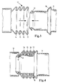
- Figure 3 shows the variant of a connection with two pipe ends, which are pushed one above the other.
- Figure 4 The pipe ends shown in Figure 3 in the superimposed end position.
- FIG. 1 and 2 there is shown a first embodiment of a pipe joint used, for example, in connecting plastic pipes 1 and 2, e.g. made of PP, is used in air intake systems in automotive engineering.
- a first flexible pipe end 3 on the pipe 1 is present, which is to be connected to a fixed pipe end 4 of the counterpart pipe 2.
- the pipe end 3 has a fold 5 and a further fold-like region 6, which is shown in detail in the non-pushed state in FIG.
- the pipe end 3 is pushed according to the figure 1 on the other pipe end 4 to a radially encircling sealing seat 7, so that the fold 5 collapses compressed by the axial pressure and tends against the sealing seat 7 and thus to an axial sealing of the tubes 1 and 2 leads.
- a locking device in the form of locking hooks 8 is provided for fixing the sealing fold 5, which overlap the area 6 and the fold 5 on the flexible pipe end 3 outside.
- An undercut 9 is provided on the latching hooks 8 against which the area 6 of the pipe end 3 presses axially against the insertion direction after the compression.
- FIG. 3 shows a second exemplary embodiment with tube ends 10 and 11, in which the fixed tube end 11 has a latching device which consists of a circumferential groove 12.
- the pipe end 10 has folds 14, 15, 16 and 17, wherein the fold 17 is formed as a first contact fold. The pipe end 10 is moved to the pipe end 11 and pushed over this pipe end.
- Figure 4 shows the end position of the pipe end 10 on the pipe end 11. After pushing the pipe end 10 is a circumferential inner region 13 of a fold 14 of the pipe end 10 under radial pressure at the pipe end 11 at. The engagement of the pipe end 10 takes place such that an axial seal is ensured by pressing against a radially encircling sealing seat 18 at the fixed pipe end 11 during pushing and compressing the folds 14, 15, 16 and 17.
- the folds 14, 15, 16 and 17 of the pipe end 10 of Figure 3 are prefabricated in terms of the angle of the folding sides so that they undergo a change in inclination in the direction of delay at least after compression. This change in inclination then corresponds in particular to the inclination of a cone-shaped sealing seat 18 at the pipe end 11.
Landscapes
- Engineering & Computer Science (AREA)
- General Engineering & Computer Science (AREA)
- Mechanical Engineering (AREA)
- Manufacturing & Machinery (AREA)
- Chemical & Material Sciences (AREA)
- Combustion & Propulsion (AREA)
- Quick-Acting Or Multi-Walled Pipe Joints (AREA)
- Joints That Cut Off Fluids, And Hose Joints (AREA)
- Joints With Pressure Members (AREA)
- Joints With Sleeves (AREA)
- Non-Disconnectible Joints And Screw-Threaded Joints (AREA)
- Mechanical Coupling Of Light Guides (AREA)
Abstract
Description
- Die Erfindung betrifft eine Verbindung zwischen zwei Rohren, wobei ein Rohrende zumindest im zu verbindenden Endbereich aus einem flexiblen und/oder elastischem Material besteht und die Rohrenden weitgehend dichtend aneinander gefügt werden sollen nach dem Oberbegriff des Hauptanspruchs.
- Stand der Technik
- Solche gattungsgemäßen Rohrverbindungen werden beispielsweise bei Luftführungssystemen verschiedenster Art angewendet, wobei insbesondere für Luftansaugsysteme in der Kraftfahrzeugtechnik flexible leicht austauschbare Rohre oder Rohrstücke benötigt werden. Außerdem muss hier auch die Dichtheit an der Verbindungsstelle gewährleistet sein, da eine genau steuerbare Luftzumessung im Luftansaugsystem erfolgt und auch auf die akustischen Bedingungen Rücksicht genommen werden muss. Es ist somit eine luftdichte, druckverlustlose und möglichst werkzeuglos verbindbare sowie lösbare Verbindung der Rohre erforderlich, welche auch höheren axialen Kräften und Vibrationen, wie sie zum Beispiel im Kraftfahrzeug vorkommen können, stand halten kann.
- Aus der
EP 1 596 301 A2 ist eine Steckverbindung für die Verbindung zweier Rohrenden bekannt, bei dem ein Ende des ersten Rohres in das Ende des Gegenstücks einsteckbar ist. Der Außendurchmesser des ersten Rohres ist dabei etwas kleiner als der Innendurchmesser des Gegenstückes, so dass das Rohr in das Gegenstück einsteckbar ist. Es ist aus diesem Stand der Technik weiterhin bekannt, dass der Verbindungsbereich eines Rohres eine größere Flexibilität als der Verbindungsbereich des anderen Rohres aufweist, wodurch diese dichtend übereinander stülpbar, bzw. auch umstülpbar sind. - Die beiden Rohrenden werden beim Stand der Technik auch dadurch fixiert, dass das einsteckbare Rohr im äußeren Bereich der Verbindungsstelle Rastnasen aufweist, mit der ein Formschluss mit dem Rohraufnahmebereich des Gegenstücks erreichbar ist. Diese Rastnasen sind umlaufend ausgebildet, so dass diese beim Überstülpen des ersten Rohres in korrespondierende Aufnahmefalten des Rohraufnahmebereichs des Gegenstückes einrasten können.
- Ferner ist noch aus der
FR 2 436 929 A1 - Offenbarung der Erfindung
- Der Erfindung liegt die Aufgabe zugrunde, eine Rohrverbindung der eingangs genannten Art auf einfache Weise so fortzubilden, dass eine einfache Herstellung und eine sicher Verbindung auch beim Auftreten von axialen und radialen Kräften auf die Verbindungsstelle gewährleistet ist.
- Eine Rohrverbindung der eingangs erwähnten Art mit einem ersten Rohrende, das mit dem Rohrende eines Gegenstücks verbindbar ist, wobei ein Rohrende derart flexibel ist, das es das andere Rohrende mit einem Dichtsitz überlappt und bei dem ein faltenähnlich aufweitbaren Bereich am flexiblen Rohrende vorhanden ist, an über das andere Rohrende bis zu einem radial umlaufenden Dichtsitz schiebbar ist, wird erfindungsgemäß mit dem Merkmalen des Hauptanspruchs weitergebildet.
- In vorteilhafter Weise wird dazu am flexiblen Rohrende mindest eine radial umlaufende Falte angebracht, die durch ein axiales Aufschieben auf das andere Rohrende bis an den Dichtsitz ein Komprimierung erfährt, die zu einer radialen Kraftkomponente des Faltenbereichs auf das andere Rohrende führt. Mit der Erfindung ist somit erreicht, dass durch die elastische Faltengestaltung auf einfache Weise eine hervorragende Dichtung des flexiblen Rohrendes zum anderen Rohrende hergestellt wird, die sowohl in axialer als auch in radialer Dichtung eine Dichtung ermöglicht.
- Somit können insbesondere für Luftansaugsysteme in Kraftfahrzeugen Rohrverbindung aus einzeln hergestellten Rohrteilen gebildet werden, die leicht an die Gegebenheiten des Kraftfahrzeuges anpassbar und trotzdem sehr gut abgedichtet sind um die in der Beschreibungseinleitung beschriebenen Nachteile für die Ansaugluftregelung und hinsichtlich der akustischen Verhältnisse zu verhindern.
- Vorteilhaft sind hier insbesondere Rohrverbindungen mit mindestens einer Rastvorrichtung, die mit dem faltenähnlich aufweitbaren Bereich am flexiblen Rohrende korrespondiert. Auf einfache Weise können hierzu am festen Rohrende eine Rastnase, ein Rasthaken und/oder eine Rastnut derart angebracht werden, dass nach der Komprimierung der mindestens einen Falte ein Eingriff der Falte in oder an der Rastvorrichtung zur axialen Fixierung und auch zur Abdichtung der Rohrenden erfolgt.
- Bei einer ersten Ausführungsform weist das feste Rohrende eine Rastvorrichtung mit Rasthaken auf, die den faltenähnlichen Bereich am flexiblen Rohrende außen überlappen und hieran jeweils ein Hinterschnitt vorhanden ist, gegen den nach der Komprimierung ein aufgefalteter Bereich axial gegen die Einschubrichtung drückt. Innerhalb des Bereichs zwischen dem Hinterschnitt und dem Dichtsitz kann somit nach dem Aufschieben des flexiblen Rohrendes ein axialer Druck zwischen dem Hinterschnitt und dem Dichtsitz und ein radialer Druck durch die komprimierte Falte erreicht werden.
- Gemäß einer anderen Vorteilhaften Ausführungsform weist das feste Rohrende eine Rastvorrichtung auf, die aus einer umlaufenden Nut am festen Rohrende besteht, in die nach der Komprimierung ein umlaufend innen liegender Bereich mindestens einer Falte des flexiblen Rohrendes eingreift. Auch hier ist somit durch das unter radialem Druck erfolgende Einrasten in der umlaufenden Nut als Rastvorrichtung eine radiale Abdichtung und durch das Andrücken an den ebenfalls radial umlaufenden Dichtsitz beim Aufschieben und Komprimieren der Falten eine axiale Dichtung gewährleistet. Besonders vorteilhaft ist es hier, wenn zur Erhöhung des radialen Anpressdrucks der umlaufend innen liegende Bereich mindestens einer Falte zum Einrasten einen kleinern Innendurchmesser aufweist als die anderen Falten.
- Die erfindungsgemäß ausgestalteten Falten können hinsichtlich des Winkels der Faltungsseiten so vorgefertigt sein, dass entweder eine oder auch alle Falten nach der Komprimierung eine Neigungsänderung in Aufschubrichtung erfahren, also praktisch in Aufschubrichtung nach außen umkippen.
- Dies ist insbesondere an der Rastvorrichtung vorteilhaft, da hier dann ein Gegendruck gegen ein Auseinanderziehen bewirkt wird und es kann darüber hinaus am Dichtsicht eine bessere Anlage erfolgen. Besonders vorteilhaft ist es hierbei, wenn die Neigungsänderung entsprechend der Neigung eines konusartigen Dichtsitzes am Ende der Falten in Aufschubrichtung erfolgt.
- Mit der Erfindung kann auf einfache Weise eine Produktionskostenreduzierung dadurch erreicht werden, dass eine Funktionsintegration der bisher über Elastomer- oder TPE-Dichtungen in die erfindungsgemäß hergestellten relativ dünnwandigen Faltenbereiche erfolgen kann.
- Die zu verbindenden Rohrteile können alle aus einem Material z.B. PP, beispielsweise als Blasteil kostengünstig hergestellt werden. Durch die Verwendung von nur einem Material ergeben sich Zyklusszeitenverkürzungen, beispielsweise in einem Corrugatorprozess, durch Vermeidung von Zwei-Komponenten-Werkzeugen und dem erfindungsgemäß vermindertem Montageaufwand.
- Ausführungsbeispiele der erfindungsgemäßen Rohrverbindung innerhalb des Ansaugtrakts eines Verbrennungsmotors werden anhand der Zeichnung erläutert. Es zeigen:
- Figur 1 Einen Schnitt durch eine Rohrverbindung über eine komprimierte Falte an einem flexiblen Rohrende, das auf ein festes Rohrende geschoben wird.
- Figur 2 Eine Detaildarstellung mit einem flexiblen Rohrende vor dem Aufschieben auf ein weiteres Rohr.
- Figur 3 Die Variante einer Verbindung mit zwei Rohrenden, die übereinander geschoben werden.
- Figur 4 Die in Figur 3 gezeigten Rohrenden in der übereinander geschobenen Endstellung.
- In Figur 1 und 2 ist ein erstes Ausführungsbeispiel einer Rohrverbindung gezeigt, die beispielsweise bei der Verbindung von Kunststoffrohren 1 und 2, z.B. aus PP, bei Luftansaugsystemen in der Kraftfahrzeugtechnik angewendet wird. Hierbei ist ein erstes flexibles Rohrende 3 am Rohr 1 vorhanden, das mit einem festen Rohrende 4 des Gegenstücks Rohr 2 verbunden werden soll.
- Das Rohrende 3 weist eine Falte 5 und einen weiteren faltenähnlichen Bereich 6 auf, der in Figur 2 im nicht aufgeschobenen Zustand im Detail gezeigt ist.
- Das Rohrende 3 ist gemäß der Figur 1 über das andere Rohrende 4 bis zu einem radial umlaufenden Dichtsitz 7 geschoben, so dass die Falte 5 durch den axialen Druck komprimiert zusammenklappt und sich gegen den Dichtsitz 7 neigt und damit zu einer axialen Abdichtung der Rohre 1 und 2 führt.
- Am Rohrende 4 des ersten Ausführungsbeispiels nach der Figur 1 ist zur Fixierung der dichtenden Falte 5 eine Rastvorrichtung in Form von Rasthaken 8 vorhanden, die den Bereich 6 und die Falte 5 am flexiblen Rohrende 3 außen überlappen. An den Rasthaken 8 ist jeweils ein Hinterschnitt 9 vorhanden, gegen den nach der Komprimierung der Bereich 6 des Rohrendes 3 axial gegen die Einschubrichtung drückt.
- Aus Figur 3 ist ein zweites Ausführungsbeispiel mit Rohrenden 10 und 11 zu entnehmen, bei dem das feste Rohrende 11 eine Rastvorrichtung aufweist, die aus einer umlaufenden Nut 12 besteht. Das Rohrende 10 weist Falten 14, 15, 16 und 17 auf, wobei die Falte 17 als erste Kontaktfalte ausgebildet ist. Das Rohrende 10 wird auf das Rohrende 11 zubewegt und über dieses Rohrende geschoben.
- Figur 4 zeigt die Endposition des Rohrendes 10 auf dem Rohrende 11. Nach dem Aufschieben des Rohrendes 10 liegt ein umlaufend innenliegender Bereich 13 einer Falte 14 des Rohrendes 10 unter radialem Druck an dem Rohrende 11 an. Das Einrasten des Rohrendes 10 erfolgt derart, dass durch das Andrücken an einen radial umlaufenden Dichtsitz 18 am festen Rohrende 11 beim Aufschieben und Komprimieren der Falten 14, 15, 16 und 17 eine axiale Dichtung gewährleistet ist.
- Die Falten 14, 15, 16 und 17 des Rohrendes 10 nach der Figur 3 sind hinsichtlich des Winkels der Faltungsseiten so vorgefertigt, dass sie zumindest nach der Komprimierung eine Neigungsänderung in Aufschubrichtung erfahren. Diese Neigungsänderung entspricht dann insbesondere der Neigung eines konusartig ausgeführten Dichtsitzes 18 am Rohrende 11.
Claims (10)
- Rohrverbindung mit einem ersten Rohrende (3; 10), das mit dem Rohrende (4;11) eines Gegenstücks verbindbar ist, wobei ein Rohrende (1;10) derart flexibel ist, das es das andere Rohrende (4;11) mit einem Dichtsitz überlappt und mit einem faltenähnlich aufweitbaren Bereich am flexiblen Rohrende (3;10), an über das andere Rohrende (4;11) bis zu einem radial umlaufenden Dichtsitz (7;18) schiebbar ist, dadurch gekennzeichnet, dass am flexiblen Rohrende (3;10) mindest eine radial umlaufende Falte (5;14,15,16,17) angebracht ist, die durch ein axiales Aufschieben auf das andere Rohrende (4;11) bis an den Dichtsitz (7;18) ein Komprimierung erfährt, die zu einer radialen Kraftkomponente des Faltenbereichs (5;14,15,16,17) auf das andere Rohrende (4;11) führt.
- Rohrverbindung nach Anspruch 1, die eine Rastvorrichtung aufweist, die mit dem faltenähnlich aufweitbaren Bereich am flexiblen Rohrende korrespondiert, dadurch gekennzeichnet, dass am anderen Rohrende (3;11) eine Rastnase, ein Rasthaken (8) und/oder eine Rastnut (12) derart angebracht ist, das nach der Komprimierung der mindestens einen Falte (5,6;14) ein Eingriff der Falte (5,6;14) in oder an der Rastvorrichtung zur axialen Fixierung der Rohrenden (3,4;10,11)erfolgt.
- Rohrverbindung nach Anspruch 2, dadurch gekennzeichnet, dass das feste Rohrende (4) eine Rastvorrichtung (8) aufweist, die den faltenähnlichen Bereich (5,6) am flexiblen Rohrende (3) außen überlappt und hieran ein Hinterschnitt (9) vorhanden ist, gegen den nach der Komprimierung ein Bereich (5) axial gegen die Einschubrichtung drückt.
- Rohrverbindung nach Anspruch 2, dadurch gekennzeichnet, dass das feste Rohrende (11) eine Rastvorrichtung aufweist, die aus einer umlaufenden Nut (12) am festen Rohrende (11) besteht, in die nach der Komprimierung ein umlaufend innen liegender Bereich (13) mindestens einer Falte (14) des flexiblen Rohrendes (10) eingreift.
- Rohrverbindung nach Anspruch 4, dadurch gekennzeichnet, dass der eine umlaufend innen liegende Bereich (13) mindestens einer Falte (14) einen kleinern Innendurchmesser aufweist als die anderen Falten (15,16,17).
- Rohrverbindung nach einem der vorhergehenden Ansprüche, dadurch gekennzeichnet, dass das flexible Rohrende (3;10) eine Mehrzahl von Falten (14,15,16,17) aufweist.
- Rohrverbindung nach einem der vorhergehenden Ansprüche, dadurch gekennzeichnet, dass die mindestens eine Falte (5;14,15,16,17) nach der Komprimierung eine Neigungsänderung in Aufschubrichtung erfährt.
- Rohrverbindung nach Anspruch 7, dadurch gekennzeichnet, dass die Neigungsänderung entsprechend der Neigung eines konusartigen Dichtsitzes (18) am Ende der Falten in Aufschubrichtung erfolgt.
- Rohrverbindung nach einem der vorhergehenden Ansprüche, dadurch gekennzeichnet, dass eines und/oder beide der zu verbindenden Rohre (1,2) einschließlich der Rohrenden (3,4;10,11) als Blasteil hergestellt sind.
- Rohrverbindung nach einem der vorhergehenden Ansprüche, dadurch gekennzeichnet, dass eines und/oder beide der zu verbindenden Rohre (1,2) einschließlich der Rohrenden (3,4;10,11) aus Polypropylen (PP) hergestellt sind.
Applications Claiming Priority (1)
| Application Number | Priority Date | Filing Date | Title |
|---|---|---|---|
| DE202005008984U DE202005008984U1 (de) | 2005-06-07 | 2005-06-07 | Rohrverbindung |
Publications (3)
| Publication Number | Publication Date |
|---|---|
| EP1731819A2 true EP1731819A2 (de) | 2006-12-13 |
| EP1731819A3 EP1731819A3 (de) | 2007-05-23 |
| EP1731819B1 EP1731819B1 (de) | 2010-04-14 |
Family
ID=36942585
Family Applications (1)
| Application Number | Title | Priority Date | Filing Date |
|---|---|---|---|
| EP06115048A Not-in-force EP1731819B1 (de) | 2005-06-07 | 2006-06-07 | Rohrverbindung |
Country Status (3)
| Country | Link |
|---|---|
| EP (1) | EP1731819B1 (de) |
| AT (1) | ATE464502T1 (de) |
| DE (2) | DE202005008984U1 (de) |
Cited By (2)
| Publication number | Priority date | Publication date | Assignee | Title |
|---|---|---|---|---|
| WO2015010854A1 (de) * | 2013-07-23 | 2015-01-29 | Mann+Hummel Gmbh | Verbindungssystem zum verbinden von zwei rohren |
| CN113266498A (zh) * | 2020-01-29 | 2021-08-17 | 曼·胡默尔有限公司 | 热塑性弹性体波纹管道 |
Citations (6)
| Publication number | Priority date | Publication date | Assignee | Title |
|---|---|---|---|---|
| FR2436929A1 (fr) | 1978-09-20 | 1980-04-18 | Carre Pierrat Jacky | Dispositif rapide de jonction des extremites de deux tubes, conduits ou similaires |
| FR2750755A1 (fr) | 1996-07-05 | 1998-01-09 | Coutier Moulage Gen Ind | Dispositif d'assemblage de deux pieces tubulaires emboitables |
| DE20113861U1 (de) | 2001-08-22 | 2002-01-24 | BRUGG Rohrsysteme GmbH, 31515 Wunstorf | Verbindung zwischen dem Ende eines schraubenlinienförmig gewellten Metallrohres mit einem Anschlußstück |
| US6428052B1 (en) | 1996-08-08 | 2002-08-06 | Omega Flex, Inc. | Fitting for use with corrugated tubing |
| EP1496301A2 (de) | 2003-07-08 | 2005-01-12 | Mann+Hummel Gmbh | Steckverbindung |
| EP1072835B1 (de) | 1999-07-08 | 2005-04-13 | Omega Flex, Inc. | Armatur für Wellrohre |
-
2005
- 2005-06-07 DE DE202005008984U patent/DE202005008984U1/de not_active Expired - Lifetime
-
2006
- 2006-06-07 DE DE502006006671T patent/DE502006006671D1/de active Active
- 2006-06-07 AT AT06115048T patent/ATE464502T1/de active
- 2006-06-07 EP EP06115048A patent/EP1731819B1/de not_active Not-in-force
Patent Citations (6)
| Publication number | Priority date | Publication date | Assignee | Title |
|---|---|---|---|---|
| FR2436929A1 (fr) | 1978-09-20 | 1980-04-18 | Carre Pierrat Jacky | Dispositif rapide de jonction des extremites de deux tubes, conduits ou similaires |
| FR2750755A1 (fr) | 1996-07-05 | 1998-01-09 | Coutier Moulage Gen Ind | Dispositif d'assemblage de deux pieces tubulaires emboitables |
| US6428052B1 (en) | 1996-08-08 | 2002-08-06 | Omega Flex, Inc. | Fitting for use with corrugated tubing |
| EP1072835B1 (de) | 1999-07-08 | 2005-04-13 | Omega Flex, Inc. | Armatur für Wellrohre |
| DE20113861U1 (de) | 2001-08-22 | 2002-01-24 | BRUGG Rohrsysteme GmbH, 31515 Wunstorf | Verbindung zwischen dem Ende eines schraubenlinienförmig gewellten Metallrohres mit einem Anschlußstück |
| EP1496301A2 (de) | 2003-07-08 | 2005-01-12 | Mann+Hummel Gmbh | Steckverbindung |
Cited By (2)
| Publication number | Priority date | Publication date | Assignee | Title |
|---|---|---|---|---|
| WO2015010854A1 (de) * | 2013-07-23 | 2015-01-29 | Mann+Hummel Gmbh | Verbindungssystem zum verbinden von zwei rohren |
| CN113266498A (zh) * | 2020-01-29 | 2021-08-17 | 曼·胡默尔有限公司 | 热塑性弹性体波纹管道 |
Also Published As
| Publication number | Publication date |
|---|---|
| ATE464502T1 (de) | 2010-04-15 |
| DE202005008984U1 (de) | 2006-10-12 |
| EP1731819A3 (de) | 2007-05-23 |
| DE502006006671D1 (de) | 2010-05-27 |
| EP1731819B1 (de) | 2010-04-14 |
Similar Documents
| Publication | Publication Date | Title |
|---|---|---|
| EP0944795B1 (de) | Zum anschluss eines schlauches mit einem zweiten bauteil vorgesehene schlauchkupplung | |
| DE69914586T2 (de) | Steck-kupplung für rohre | |
| EP2057401B1 (de) | System zur vorpositionierung einer schlauchschelle auf einem schlauchende, insbesondere eines ladeluft- und kühlwasserschlauchs | |
| DE102006062894B4 (de) | Schutzkappe | |
| DE10139899B4 (de) | Kunststoffwellrohranordnung | |
| EP3121501A1 (de) | Fahrzeugkomponente und kraftfahrzeug | |
| EP1673185B1 (de) | Verfahren und vorrichtung zur herstellung einer rohrpressverbindung an einer steckverbindung | |
| WO2006039882A1 (de) | Anschlussanordnung zum anschliessen einer rohrleitung an ein system | |
| EP3645926A1 (de) | Presshülse | |
| EP2357390A2 (de) | Anschlussverbindung für ein Rohr | |
| EP4083486B1 (de) | Leitungskupplung | |
| EP1496301B1 (de) | Steckverbindung | |
| EP1731819B1 (de) | Rohrverbindung | |
| DE202021100271U1 (de) | Gegensteckverbinder zum Verbinden von Bauteilen für flüssige oder gasförmige Medien, sowie eine Steckerbaugruppe | |
| DE102008058675B4 (de) | Steckverbindung | |
| WO2008058581A2 (de) | Dichtungsanordnung zur abdichtung einer durchgangsöffnung und montageverfahren | |
| DE102018208508A1 (de) | Fluidverbindungsadapter, Fluidverbindungsanordnung sowie Verfahren zum Herstellen einer Fluidverbindungsanordnung | |
| DE19731563A1 (de) | Verfahren zur Herstellung einer dichten und festen Rohrverbindung | |
| DE202006016187U1 (de) | Ladeluftschlauchadapter | |
| EP2952798A1 (de) | Konnektor für ein hydraulisches kupplungssystem | |
| EP3130791B1 (de) | Baugruppe für einen ansaugtrakt einer brennkraftmaschine | |
| AT525582B1 (de) | Rohrverbinder zum Führen von flüssigen und/oder gasförmigen Medien, sowie Rohrverbinderzusammenstellung und Verfahren zum Herstellen des Rohrverbinders, sowie Verfahren zum Herstellen der Rohrverbinderzusammenstellung | |
| DE19960650C1 (de) | Rohrleitung mit Anschlußstück | |
| WO2018206042A1 (de) | Anordnung zum verbinden eines ersten und eines zweiten leitungselements | |
| WO2022122277A1 (de) | Quetschkupplung zur verbindung eines schlauches mit einer rohrleitung |
Legal Events
| Date | Code | Title | Description |
|---|---|---|---|
| PUAI | Public reference made under article 153(3) epc to a published international application that has entered the european phase |
Free format text: ORIGINAL CODE: 0009012 |
|
| AK | Designated contracting states |
Kind code of ref document: A2 Designated state(s): AT BE BG CH CY CZ DE DK EE ES FI FR GB GR HU IE IS IT LI LT LU LV MC NL PL PT RO SE SI SK TR |
|
| AX | Request for extension of the european patent |
Extension state: AL BA HR MK YU |
|
| PUAL | Search report despatched |
Free format text: ORIGINAL CODE: 0009013 |
|
| AK | Designated contracting states |
Kind code of ref document: A3 Designated state(s): AT BE BG CH CY CZ DE DK EE ES FI FR GB GR HU IE IS IT LI LT LU LV MC NL PL PT RO SE SI SK TR |
|
| AX | Request for extension of the european patent |
Extension state: AL BA HR MK YU |
|
| 17P | Request for examination filed |
Effective date: 20070703 |
|
| 17Q | First examination report despatched |
Effective date: 20070807 |
|
| AKX | Designation fees paid |
Designated state(s): AT BE BG CH CY CZ DE DK EE ES FI FR GB GR HU IE IS IT LI LT LU LV MC NL PL PT RO SE SI SK TR |
|
| GRAP | Despatch of communication of intention to grant a patent |
Free format text: ORIGINAL CODE: EPIDOSNIGR1 |
|
| GRAS | Grant fee paid |
Free format text: ORIGINAL CODE: EPIDOSNIGR3 |
|
| GRAA | (expected) grant |
Free format text: ORIGINAL CODE: 0009210 |
|
| AK | Designated contracting states |
Kind code of ref document: B1 Designated state(s): AT BE BG CH CY CZ DE DK EE ES FI FR GB GR HU IE IS IT LI LT LU LV MC NL PL PT RO SE SI SK TR |
|
| REG | Reference to a national code |
Ref country code: GB Ref legal event code: FG4D Free format text: NOT ENGLISH |
|
| REG | Reference to a national code |
Ref country code: CH Ref legal event code: EP |
|
| REG | Reference to a national code |
Ref country code: IE Ref legal event code: FG4D Free format text: LANGUAGE OF EP DOCUMENT: GERMAN |
|
| REF | Corresponds to: |
Ref document number: 502006006671 Country of ref document: DE Date of ref document: 20100527 Kind code of ref document: P |
|
| REG | Reference to a national code |
Ref country code: NL Ref legal event code: VDEP Effective date: 20100414 |
|
| LTIE | Lt: invalidation of european patent or patent extension |
Effective date: 20100414 |
|
| PG25 | Lapsed in a contracting state [announced via postgrant information from national office to epo] |
Ref country code: ES Free format text: LAPSE BECAUSE OF FAILURE TO SUBMIT A TRANSLATION OF THE DESCRIPTION OR TO PAY THE FEE WITHIN THE PRESCRIBED TIME-LIMIT Effective date: 20100725 Ref country code: SE Free format text: LAPSE BECAUSE OF FAILURE TO SUBMIT A TRANSLATION OF THE DESCRIPTION OR TO PAY THE FEE WITHIN THE PRESCRIBED TIME-LIMIT Effective date: 20100414 Ref country code: NL Free format text: LAPSE BECAUSE OF FAILURE TO SUBMIT A TRANSLATION OF THE DESCRIPTION OR TO PAY THE FEE WITHIN THE PRESCRIBED TIME-LIMIT Effective date: 20100414 Ref country code: LT Free format text: LAPSE BECAUSE OF FAILURE TO SUBMIT A TRANSLATION OF THE DESCRIPTION OR TO PAY THE FEE WITHIN THE PRESCRIBED TIME-LIMIT Effective date: 20100414 |
|
| REG | Reference to a national code |
Ref country code: IE Ref legal event code: FD4D |
|
| PG25 | Lapsed in a contracting state [announced via postgrant information from national office to epo] |
Ref country code: SI Free format text: LAPSE BECAUSE OF FAILURE TO SUBMIT A TRANSLATION OF THE DESCRIPTION OR TO PAY THE FEE WITHIN THE PRESCRIBED TIME-LIMIT Effective date: 20100414 Ref country code: LV Free format text: LAPSE BECAUSE OF FAILURE TO SUBMIT A TRANSLATION OF THE DESCRIPTION OR TO PAY THE FEE WITHIN THE PRESCRIBED TIME-LIMIT Effective date: 20100414 Ref country code: IS Free format text: LAPSE BECAUSE OF FAILURE TO SUBMIT A TRANSLATION OF THE DESCRIPTION OR TO PAY THE FEE WITHIN THE PRESCRIBED TIME-LIMIT Effective date: 20100814 Ref country code: FI Free format text: LAPSE BECAUSE OF FAILURE TO SUBMIT A TRANSLATION OF THE DESCRIPTION OR TO PAY THE FEE WITHIN THE PRESCRIBED TIME-LIMIT Effective date: 20100414 |
|
| BERE | Be: lapsed |
Owner name: MANN+HUMMEL G.M.B.H. Effective date: 20100630 |
|
| PG25 | Lapsed in a contracting state [announced via postgrant information from national office to epo] |
Ref country code: GR Free format text: LAPSE BECAUSE OF FAILURE TO SUBMIT A TRANSLATION OF THE DESCRIPTION OR TO PAY THE FEE WITHIN THE PRESCRIBED TIME-LIMIT Effective date: 20100715 Ref country code: CY Free format text: LAPSE BECAUSE OF FAILURE TO SUBMIT A TRANSLATION OF THE DESCRIPTION OR TO PAY THE FEE WITHIN THE PRESCRIBED TIME-LIMIT Effective date: 20100505 Ref country code: PL Free format text: LAPSE BECAUSE OF FAILURE TO SUBMIT A TRANSLATION OF THE DESCRIPTION OR TO PAY THE FEE WITHIN THE PRESCRIBED TIME-LIMIT Effective date: 20100414 |
|
| PG25 | Lapsed in a contracting state [announced via postgrant information from national office to epo] |
Ref country code: MC Free format text: LAPSE BECAUSE OF NON-PAYMENT OF DUE FEES Effective date: 20100630 Ref country code: EE Free format text: LAPSE BECAUSE OF FAILURE TO SUBMIT A TRANSLATION OF THE DESCRIPTION OR TO PAY THE FEE WITHIN THE PRESCRIBED TIME-LIMIT Effective date: 20100414 Ref country code: IE Free format text: LAPSE BECAUSE OF FAILURE TO SUBMIT A TRANSLATION OF THE DESCRIPTION OR TO PAY THE FEE WITHIN THE PRESCRIBED TIME-LIMIT Effective date: 20100414 Ref country code: PT Free format text: LAPSE BECAUSE OF FAILURE TO SUBMIT A TRANSLATION OF THE DESCRIPTION OR TO PAY THE FEE WITHIN THE PRESCRIBED TIME-LIMIT Effective date: 20100816 Ref country code: DK Free format text: LAPSE BECAUSE OF FAILURE TO SUBMIT A TRANSLATION OF THE DESCRIPTION OR TO PAY THE FEE WITHIN THE PRESCRIBED TIME-LIMIT Effective date: 20100414 |
|
| REG | Reference to a national code |
Ref country code: CH Ref legal event code: PL |
|
| PLBE | No opposition filed within time limit |
Free format text: ORIGINAL CODE: 0009261 |
|
| STAA | Information on the status of an ep patent application or granted ep patent |
Free format text: STATUS: NO OPPOSITION FILED WITHIN TIME LIMIT |
|
| PG25 | Lapsed in a contracting state [announced via postgrant information from national office to epo] |
Ref country code: SK Free format text: LAPSE BECAUSE OF FAILURE TO SUBMIT A TRANSLATION OF THE DESCRIPTION OR TO PAY THE FEE WITHIN THE PRESCRIBED TIME-LIMIT Effective date: 20100414 Ref country code: RO Free format text: LAPSE BECAUSE OF FAILURE TO SUBMIT A TRANSLATION OF THE DESCRIPTION OR TO PAY THE FEE WITHIN THE PRESCRIBED TIME-LIMIT Effective date: 20100414 Ref country code: CZ Free format text: LAPSE BECAUSE OF FAILURE TO SUBMIT A TRANSLATION OF THE DESCRIPTION OR TO PAY THE FEE WITHIN THE PRESCRIBED TIME-LIMIT Effective date: 20100414 |
|
| 26N | No opposition filed |
Effective date: 20110117 |
|
| GBPC | Gb: european patent ceased through non-payment of renewal fee |
Effective date: 20100714 |
|
| PG25 | Lapsed in a contracting state [announced via postgrant information from national office to epo] |
Ref country code: IT Free format text: LAPSE BECAUSE OF FAILURE TO SUBMIT A TRANSLATION OF THE DESCRIPTION OR TO PAY THE FEE WITHIN THE PRESCRIBED TIME-LIMIT Effective date: 20100414 |
|
| PG25 | Lapsed in a contracting state [announced via postgrant information from national office to epo] |
Ref country code: LI Free format text: LAPSE BECAUSE OF NON-PAYMENT OF DUE FEES Effective date: 20100630 Ref country code: CH Free format text: LAPSE BECAUSE OF NON-PAYMENT OF DUE FEES Effective date: 20100630 |
|
| PG25 | Lapsed in a contracting state [announced via postgrant information from national office to epo] |
Ref country code: BE Free format text: LAPSE BECAUSE OF NON-PAYMENT OF DUE FEES Effective date: 20100630 |
|
| PG25 | Lapsed in a contracting state [announced via postgrant information from national office to epo] |
Ref country code: GB Free format text: LAPSE BECAUSE OF NON-PAYMENT OF DUE FEES Effective date: 20100714 |
|
| PG25 | Lapsed in a contracting state [announced via postgrant information from national office to epo] |
Ref country code: HU Free format text: LAPSE BECAUSE OF FAILURE TO SUBMIT A TRANSLATION OF THE DESCRIPTION OR TO PAY THE FEE WITHIN THE PRESCRIBED TIME-LIMIT Effective date: 20101015 Ref country code: LU Free format text: LAPSE BECAUSE OF NON-PAYMENT OF DUE FEES Effective date: 20100607 Ref country code: BG Free format text: LAPSE BECAUSE OF FAILURE TO SUBMIT A TRANSLATION OF THE DESCRIPTION OR TO PAY THE FEE WITHIN THE PRESCRIBED TIME-LIMIT Effective date: 20100414 |
|
| PG25 | Lapsed in a contracting state [announced via postgrant information from national office to epo] |
Ref country code: TR Free format text: LAPSE BECAUSE OF FAILURE TO SUBMIT A TRANSLATION OF THE DESCRIPTION OR TO PAY THE FEE WITHIN THE PRESCRIBED TIME-LIMIT Effective date: 20100414 |
|
| REG | Reference to a national code |
Ref country code: AT Ref legal event code: MM01 Ref document number: 464502 Country of ref document: AT Kind code of ref document: T Effective date: 20110607 |
|
| PG25 | Lapsed in a contracting state [announced via postgrant information from national office to epo] |
Ref country code: AT Free format text: LAPSE BECAUSE OF NON-PAYMENT OF DUE FEES Effective date: 20110607 |
|
| PG25 | Lapsed in a contracting state [announced via postgrant information from national office to epo] |
Ref country code: BG Free format text: LAPSE BECAUSE OF FAILURE TO SUBMIT A TRANSLATION OF THE DESCRIPTION OR TO PAY THE FEE WITHIN THE PRESCRIBED TIME-LIMIT Effective date: 20100714 |
|
| REG | Reference to a national code |
Ref country code: FR Ref legal event code: PLFP Year of fee payment: 10 |
|
| PGFP | Annual fee paid to national office [announced via postgrant information from national office to epo] |
Ref country code: DE Payment date: 20150619 Year of fee payment: 10 |
|
| PGFP | Annual fee paid to national office [announced via postgrant information from national office to epo] |
Ref country code: FR Payment date: 20150619 Year of fee payment: 10 |
|
| REG | Reference to a national code |
Ref country code: DE Ref legal event code: R119 Ref document number: 502006006671 Country of ref document: DE |
|
| REG | Reference to a national code |
Ref country code: FR Ref legal event code: ST Effective date: 20170228 |
|
| PG25 | Lapsed in a contracting state [announced via postgrant information from national office to epo] |
Ref country code: DE Free format text: LAPSE BECAUSE OF NON-PAYMENT OF DUE FEES Effective date: 20170103 Ref country code: FR Free format text: LAPSE BECAUSE OF NON-PAYMENT OF DUE FEES Effective date: 20160630 |