EP1731014A1 - Vehicle - Google Patents
Vehicle Download PDFInfo
- Publication number
- EP1731014A1 EP1731014A1 EP06011823A EP06011823A EP1731014A1 EP 1731014 A1 EP1731014 A1 EP 1731014A1 EP 06011823 A EP06011823 A EP 06011823A EP 06011823 A EP06011823 A EP 06011823A EP 1731014 A1 EP1731014 A1 EP 1731014A1
- Authority
- EP
- European Patent Office
- Prior art keywords
- vehicle according
- drive
- roller
- axis
- vehicle
- Prior art date
- Legal status (The legal status is an assumption and is not a legal conclusion. Google has not performed a legal analysis and makes no representation as to the accuracy of the status listed.)
- Granted
Links
- 239000007789 gas Substances 0.000 abstract description 4
- 125000001145 hydrido group Chemical group *[H] 0.000 abstract 3
- 239000000446 fuel Substances 0.000 abstract 1
- 230000005484 gravity Effects 0.000 description 2
- 241001417527 Pempheridae Species 0.000 description 1
- 229910000831 Steel Inorganic materials 0.000 description 1
- 239000012620 biological material Substances 0.000 description 1
- 235000013399 edible fruits Nutrition 0.000 description 1
- 230000001771 impaired effect Effects 0.000 description 1
- 238000004519 manufacturing process Methods 0.000 description 1
- 239000002184 metal Substances 0.000 description 1
- 239000002689 soil Substances 0.000 description 1
- 239000010959 steel Substances 0.000 description 1
Images


Classifications
-
- E—FIXED CONSTRUCTIONS
- E02—HYDRAULIC ENGINEERING; FOUNDATIONS; SOIL SHIFTING
- E02D—FOUNDATIONS; EXCAVATIONS; EMBANKMENTS; UNDERGROUND OR UNDERWATER STRUCTURES
- E02D3/00—Improving or preserving soil or rock, e.g. preserving permafrost soil
- E02D3/02—Improving by compacting
- E02D3/026—Improving by compacting by rolling with rollers usable only for or specially adapted for soil compaction, e.g. sheepsfoot rollers
-
- A—HUMAN NECESSITIES
- A01—AGRICULTURE; FORESTRY; ANIMAL HUSBANDRY; HUNTING; TRAPPING; FISHING
- A01B—SOIL WORKING IN AGRICULTURE OR FORESTRY; PARTS, DETAILS, OR ACCESSORIES OF AGRICULTURAL MACHINES OR IMPLEMENTS, IN GENERAL
- A01B33/00—Tilling implements with rotary driven tools, e.g. in combination with fertiliser distributors or seeders, with grubbing chains, with sloping axles, with driven discs
- A01B33/08—Tools; Details, e.g. adaptations of transmissions or gearings
- A01B33/082—Transmissions; Gearings; Power distribution
-
- A—HUMAN NECESSITIES
- A01—AGRICULTURE; FORESTRY; ANIMAL HUSBANDRY; HUNTING; TRAPPING; FISHING
- A01B—SOIL WORKING IN AGRICULTURE OR FORESTRY; PARTS, DETAILS, OR ACCESSORIES OF AGRICULTURAL MACHINES OR IMPLEMENTS, IN GENERAL
- A01B45/00—Machines for treating meadows or lawns, e.g. for sports grounds
- A01B45/02—Machines for treating meadows or lawns, e.g. for sports grounds for aerating
- A01B45/023—Perforators comprising spiking tools actively driven in a reciprocating movement through a crankshaft or eccentric mechanism
Definitions
- the invention relates to a vehicle with a drive for at least one travel roller with a roll shell, on the surface of which projections are located.
- hand-held single-axle tractors such as motor mowers, rotary tedders, belt rakes but also outside of the agricultural sector, such as sweepers and snow blowers.
- the present invention has for its object to provide a vehicle of the above. To create kind, which is more versatile and has little tendency to tip over. Furthermore, noise and exhaust emissions are to be reduced and the cutting width increased.
- This feature applies on the one hand for the direct drive of the travel roller itself, which may for example consist of a wheel hub motor.
- the wheel hub motor could for example be operated electrically, but preferred is a hydraulic drive via hydraulic pumps.
- the corresponding hydraulic unit preferably also sits in the travel roller.
- an auxiliary drive for the working equipment it makes sense to couple the auxiliary drive with the hydraulic drive for the wheel hub motors, so that the hydraulic unit serves, for example, three hydraulic pumps.
- a hydraulic pump is intended for the working equipment.
- the other two hydraulic pumps each for a wheel hub motor.
- the hydraulic unit is preferably driven by a motor.
- a motor is a fuel-powered engine, for example, a four-stroke gasoline engine.
- other possibilities are conceivable, such as corresponding electric motors.
- the drive rollers should have corresponding air openings for the intake of air. Exhaust gases from this engine are routed outside via an exhaust pipe and an exhaust pipe, with the exhaust pipe facing downwards, so that the operator is not exposed to exhaust gases.
- all or at least the majority of the drive elements are arranged below the axis or around the axis, so that the center of gravity is kept as low as possible.
- the arrangement of the drive units in the drive roller ensures that noise emission is reduced to a minimum. It is almost a whispering machine.
- hubs should be placed on one axle on both sides and a drive roller should be pushed onto each hub.
- Each hub should be assigned its own controllable drive, that is, each individual drive roller can be accelerated or decelerated separately. This can be done by appropriate tap-change or by a continuous speed control.
- Each drive roller has an opening relative to the hub, with the openings of the two drive rollers facing each other.
- a support ring In the opening of the travel roller sits a support ring, which is supported and thus the travel roller relative to the axis.
- roller bearings In order for the drive roller to be able to run around the support ring, roller bearings protrude from the support ring, on which roller the inner surface of the travel roller unrolls.
- all other bearings are possible here and should be included in the spirit of the invention.
- the two drive rollers keep a distance from each other, at this distance preferably the o.g. Exhaust is sitting, whose exhaust pipe is oriented downwards.
- a guiding device connected to the axle can protrude, wherein it is also within the scope of the invention for the entire vehicle to be remotely controlled, for example via GPS.
- a camera could be mounted on the vehicle, further a transmitting / receiving device, which transmits the necessary driving data to a central office. From this center then the vehicle is remotely controlled.
- the vehicle is conceivable as a single-axle or as a multi-axle.
- it could be designed as a two-axle as a flatbed be, for example in fruit production.
- the two drive rollers are assigned to two other wheels on a second axis, these wheels are in turn independently rotatable. In a simple embodiment, this is done about a vertical axis with any gear unit that causes the wheels to rotate about this vertical axis. Again, many possibilities are conceivable.
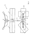
- a vehicle P 1 according to the invention has two drive rollers 1.1 and 1.2 whose roller jacket 2 is occupied by spiky projections 3 in each case.
- These openings 5 may additionally be covered by a grid, not shown in detail, so that no dirt or biological material can pass through the openings 5 in the interior of the travel roller 1.1 or 1.2.
- Each travel roller 1.1 or 1.2 is pushed onto a hub 6.1 or 6.2, each of which sits on a shaft 7 at one end.
- the axis 7 substantially passes through the travel roller 1.1 and the travel roller 1.2, wherein the hubs 6.1 and 6.2 can rotate about the axis 7.
- each wheel hub motors 8.1 and 8.2 are provided which are fixed for example on the axis 7 and have known drive elements which rotate the hubs 6.1 and 6.2 about the shaft 7.
- the hydraulic unit 9 has three hydraulic pumps 10.1, 10.2 and 10.3 and communicates via lines not shown in detail with a manifold 11 and a hydraulic tank 12 in connection.
- the pump 10.3 feeds a working device which can be fixed to a connecting flange 13, which in turn is connected to the axle 7 or corresponding chassis parts.
- the pumps 10.1 and 10.2 feed the wheel hub motors 8.1 and 8.2.
- the hydraulic unit 9 is in turn assigned within the travel roller 1.1, a motor 14, which may be, for example, a four-stroke gasoline engine. This drives the hydraulic unit.
- the exhaust gases of the engine 14 are passed through an exhaust pipe 15 in a gap 16 between the two drive rollers 1.1 and 1.2 to the outside, with an exhaust pipe 17 is directed downward.
- roller bearings 21 are provided, which, as indicated in Figure 1, slightly above the support ring 20.1 or 20.2 stand out, so that the roller can roll 1.1 or 1.2 on these roller bearings 21.
- a guide device 22 is provided, which will not be described in more detail, since it consists essentially of a handle and control elements for the operation of the vehicle P 1 .
- This guide device 22 is connected in any way with the chassis or the axis 7.
- the operation of the present vehicle is the following:
- a cutter bar is flanged, with which a steep slope to be mowed.
- the motor 14 is set in motion, which drives the hydraulic pumps 9.1, 10.2 and 10.3 via the hydraulic unit 9. Since the hydraulic pumps 10.1 and 10.2 are separately controllable, the entire vehicle P 1 can be steered by accelerating or decelerating the respective wheel hub motors 8.1 and 8.2.
- the cutter bar is driven by the hydraulic pump 10.3.
- roller rollers 1.1 and 1.2 When driving the roller rollers 1.1 and 1.2 roll with the hubs 6.1 and 6.2 about the axis 7, while they run in the region of their openings 19.1 and 19.2 the respective support ring 20.1 and 20.2 supported by the roller layer 21.
- FIG. 3 shows a further exemplary embodiment of a vehicle P 2 according to the invention. This is guided by the guide device 22, wherein the guide means 22 can also be omitted, as long as it is a remote-controlled vehicle.
- the axle 24 has in each case at its outer ends a vertical axis 25.1 and 25.2, around which in each case a wheel 26.1 or 26.2 can rotate.
- the wheels 26.1 and 26.2 may also be formed as rollers, preferably also as drive rollers similar to the drive rollers 1.1 and 1.2.
- each vertical axis 25.1 and 25.2 is seated on a guide wheel 27, which is coupled via an endless chain 28 with a drive wheel 29.
- This drive wheel 29 is also seated on the axis 24.
- a drive 30, in particular a hydraulic drive Via the hydraulic drive 30, the drive wheel 29 and with this via the chain 28, the guide wheel 27 and the vertical axis 25 are rotated, so that the wheel 26.1 and 26.2 assumes a desired driving position.
- the driving position shown in FIG. 3 is then assumed when the vehicle P 2 is to rotate in place about the travel roller 1.2.
- the necessary adjustment of the wheels 26.1 and 26.2 takes over a control.
Abstract
Description
Die Erfindung betrifft ein Fahrzeug mit einem Antrieb für zumindest eine Fahrwalze mit einem Walzenmantel, auf dessen Oberfläche sich Vorsprünge befinden.The invention relates to a vehicle with a drive for at least one travel roller with a roll shell, on the surface of which projections are located.
Insbesondere im landwirtschaftlichen Bereich gibt es eine Vielzahl von Fahrzeugen, die erheblichen Anforderungen ausgesetzt sind. Diese Fahrzeuge werden oft in schwierigem Gelände eingesetzt, beispielsweise werden mit ihnen extremste Steilhänge bearbeitet.Especially in the agricultural sector, there are a variety of vehicles that are exposed to significant requirements. These vehicles are often used in difficult terrain, for example, they are processed with the most extreme steep slopes.
Zu erwähnen sind vor allem handgeführte Einachser, wie beispielsweise Motormäher, Kreiselheuer, Bandrechen aber auch ausserhalb des landwirtschaftlichen Bereichs, beispielsweise Kehrmaschinen und Schneeräumer.Particularly noteworthy are hand-held single-axle tractors, such as motor mowers, rotary tedders, belt rakes but also outside of the agricultural sector, such as sweepers and snow blowers.
Für derartige Fahrzeuge werden vor allem Räder mit einer Gummibereifung angeboten, wobei die Verwendung derartiger Mäher beispielsweise im steilen Gelände seine Grenzen hat. Hier werden anstelle der Gummiräder, beispielsweise Stahl-Gitterräder oder sogenannte Stachelwalzen eingesetzt, wobei beispielsweise anstelle der Gummiräder seitlich an die Achse eines Motormähers jeweils eine Stachelwalze montiert wird. Die Stacheln dieser Stachelwalzen graben sich in den Boden ein, wodurch extremste Steilhänge bearbeitet werden können. Durch die vielen Auflagepunkte bieten die Stachelwalzen sehr guten Halt und verhindern dadurch ein Aufreissen und Einschneiden der Grasnabe.For such vehicles especially wheels are offered with a rubber tires, the use of such mowers, for example, has its limits on steep terrain. Here, instead of the rubber wheels, for example, steel lattice wheels or so-called spiked rollers used, for example, instead of the rubber wheels laterally to the axis of a motor mower a spiked roller is mounted. The spikes of these spiked wheels dig into the ground, allowing the most extreme steep slopes to be worked. Due to the many contact points, the spiked rollers provide very good grip and thus prevent the turf from being torn open and cut.
Ein wesentliches Augenmerk ist bei derartigen Fahrzeugen auf den Schwerpunkt gerichtet. Bei den bekannten Fahrzeugen liegen die Antriebsaggregate in der Regel so hoch, dass das Fahrzeug leicht umkippt. Je schräger die Maschine gestellt wird und je höher die Aggregate liegen, desto eher kippt sie um. Andererseits kann das Fahrzeug tiefer gelegt werden, wodurch jedoch die Bodenfreiheit beeinträchtigt wird; die insbesondere bei unebenem Gelände bzw. Gelände mit Bodenwuchs zu beachten ist.A major focus in such vehicles is focused on the center of gravity. In the known vehicles, the drive units are usually so high that the vehicle easily overturns. The more inclined the machine is placed and the higher the units are, the more likely it is to tip over. On the other hand, the vehicle can be lowered, which, however, the ground clearance is impaired; which must be observed especially on uneven terrain or terrain with soil growth.
Der vorliegenden Erfindung liegt die Aufgabe zugrunde, ein Fahrzeug der o.g. Art zu schaffen, welches vielfältiger einsetzbar ist und wenig zum Umkippen neigt. Ferner sollen Lärm- und Abgasemissionen reduziert und die Schnittbreite erhöht werden.The present invention has for its object to provide a vehicle of the above. To create kind, which is more versatile and has little tendency to tip over. Furthermore, noise and exhaust emissions are to be reduced and the cutting width increased.
Zur Lösung der Aufgabe führt, dass der Antrieb in der Fahrwalze angeordnet ist.To achieve the object results in that the drive is arranged in the travel roller.
Dieses Merkmal gilt zum einen für den direkten Antrieb der Fahrwalze selbst, der beispielsweise aus einem Radnabenmotor bestehen kann. Der Radnabenmotor könnte beispielsweise elektrisch betrieben werden, bevorzugt wird jedoch ein hydraulischer Antrieb über Hydropumpen. In diesem Fall sitzt das entsprechende Hydraulikaggregat vorzugsweise ebenfalls in der Fahrwalze. Das gleiche gilt auch für einen Zusatzantrieb für die Arbeitsgerätschaft. Hier bietet es sich an, den Zusatzantrieb mit dem Hydroantrieb für die Radnabenmotoren zu koppeln, so dass das Hydroaggregat beispielsweise drei Hydropumpen bedient. Eine Hydropumpe ist für die Arbeitsgerätschaft gedacht. Die beiden anderen Hydropumpen jeweils für einen Radnabenmotor.This feature applies on the one hand for the direct drive of the travel roller itself, which may for example consist of a wheel hub motor. The wheel hub motor could for example be operated electrically, but preferred is a hydraulic drive via hydraulic pumps. In this case, the corresponding hydraulic unit preferably also sits in the travel roller. The same applies to an auxiliary drive for the working equipment. Here it makes sense to couple the auxiliary drive with the hydraulic drive for the wheel hub motors, so that the hydraulic unit serves, for example, three hydraulic pumps. A hydraulic pump is intended for the working equipment. The other two hydraulic pumps each for a wheel hub motor.
Das Hydroaggregat wird bevorzugt von einem Motor angetrieben. Hier bietet sich ein kraftstoffgespeister Motor an, beispielsweise ein Vier-Takt-Benzinmotor. Jedoch sind auch andere Möglichkeiten denkbar, wie beispielsweise entsprechende Elektromotoren.The hydraulic unit is preferably driven by a motor. Here is a fuel-powered engine, for example, a four-stroke gasoline engine. However, other possibilities are conceivable, such as corresponding electric motors.
Wird ein kraftstoffbetriebener Benzinmotor vorgesehen, so sollten die Fahrwalzen entsprechende Luftöffnungen zum Ansaugen von Luft aufweisen. Abgase dieses Motors werden über einen Auspuff und ein Auspuffrohr nach aussen geführt, wobei das Auspuffrohr nach unten gerichtet ist, so dass die Bedienperson keinen Abgasen ausgesetzt ist.If a fuel-powered gasoline engine is provided, then the drive rollers should have corresponding air openings for the intake of air. Exhaust gases from this engine are routed outside via an exhaust pipe and an exhaust pipe, with the exhaust pipe facing downwards, so that the operator is not exposed to exhaust gases.
Bevorzugt werden sämtliche oder zumindest der grösste Teil der Antriebselemente unterhalb der Achse oder um die Achse herum angeordnet, so dass der Schwerpunkt möglichst tief gehalten wird. Durch die Anordnung der Antriebsaggregate in der Fahrwalze wird gewährleistet, dass eine Lärmemission auf ein Minimum reduziert ist. Es handelt sich beinahe um eine Flüstermaschine.Preferably, all or at least the majority of the drive elements are arranged below the axis or around the axis, so that the center of gravity is kept as low as possible. The arrangement of the drive units in the drive roller ensures that noise emission is reduced to a minimum. It is almost a whispering machine.
In einem bevorzugten Ausführungsbeispiel sollen auf einer Achse beidseitig Naben aufgesetzt und auf jede Nabe eine Fahrwalze aufgeschoben sein.In a preferred embodiment, hubs should be placed on one axle on both sides and a drive roller should be pushed onto each hub.
Hierdurch ist es möglich, beispielsweise einen Balkenmäher herzustellen, der eine Schnittbreite von über 4 m, sogar bis 6 m hat.This makes it possible, for example, produce a bar mower, which has a cutting width of about 4 m, even up to 6 m.
Dabei soll jeder Nabe ein eigener ansteuerbarer Antrieb zugeordnet sein, d.h., jede einzelne Fahrwalze kann separat beschleunigt oder abgebremst werden. Dies kann durch entsprechende Stufenschaltung oder aber durch eine kontinuierliche Geschwindigkeitsregelung geschehen.Each hub should be assigned its own controllable drive, that is, each individual drive roller can be accelerated or decelerated separately. This can be done by appropriate tap-change or by a continuous speed control.
Jede Fahrwalze weist gegenüber der Nabe eine Öffnung auf, wobei die Öffnungen der beiden Fahrwalzen sich gegenüberliegen. In der Öffnung der Fahrwalze sitzt ein Stützring, der sich und damit auch die Fahrwalze gegenüber der Achse abstützt. Damit die Fahrwalze um den Stützring herumlaufen kann, ragen aus dem Stützring Rollenlager, auf denen sich die Innenfläche der Fahrwalze abrollt. Selbstverständlich sind hier auch alle anderen Lager möglich und sollten vom Erfindungsgedanken umfasst sein.Each drive roller has an opening relative to the hub, with the openings of the two drive rollers facing each other. In the opening of the travel roller sits a support ring, which is supported and thus the travel roller relative to the axis. In order for the drive roller to be able to run around the support ring, roller bearings protrude from the support ring, on which roller the inner surface of the travel roller unrolls. Of course, all other bearings are possible here and should be included in the spirit of the invention.
Die beiden Fahrwalzen halten einen Abstand voneinander ein, wobei in diesem Abstand bevorzugt der o.g. Auspuff sitzt, dessen Auspuffrohr nach unten ausgerichtet ist.The two drive rollers keep a distance from each other, at this distance preferably the o.g. Exhaust is sitting, whose exhaust pipe is oriented downwards.
Aus dem Abstand bzw. Spalt zwischen den beiden Fahrwalzen ragt dann auch ein Arm heraus, an dem sich ein Flansch zum Festlegen der oben erwähnten Arbeitsgerätschaft befindet. Ebenso kann aus diesem Abstand eine mit der Achse verbundene Führungseinrichtung herausragen, wobei es auch im Rahmen der Erfindung liegt, dass das ganze Fahrzeug ferngesteuert, beispielsweise über GPS gelenkt wird. Hierzu könnte auf dem Fahrzeug eine Kamera montiert sein, ferner eine Sende-/Empfangseinrichtung, welche die notwendigen Fahrdaten an eine Zentrale übermittelt. Von dieser Zentrale aus wird dann das Fahrzeug femgesteuert.From the distance or gap between the two drive rollers then projects out an arm on which there is a flange for fixing the above-mentioned working equipment. Likewise, from this distance, a guiding device connected to the axle can protrude, wherein it is also within the scope of the invention for the entire vehicle to be remotely controlled, for example via GPS. For this purpose, a camera could be mounted on the vehicle, further a transmitting / receiving device, which transmits the necessary driving data to a central office. From this center then the vehicle is remotely controlled.
Das Fahrzeug ist als Einachser oder auch als Mehrachser denkbar. Insbesondere könnte es als Zweiachser auch als Pritschenwagen ausgestaltet sein, z.B. im Obstbau. In diesem Fall werden den beiden Fahrwalzen zwei weitere Räder an einer zweiten Achse zugeordnet, wobei diese Räder wiederum selbständig drehbar sind. In einem einfachen Ausführungsbeispiel geschieht dies um eine Vertikalachse mit einer beliebigen Getriebeeinheit, die bewirkt, dass die Räder um diese Vertikalachse drehen. Auch hier sind viele Möglichkeiten denkbar.The vehicle is conceivable as a single-axle or as a multi-axle. In particular, it could be designed as a two-axle as a flatbed be, for example in fruit production. In this case, the two drive rollers are assigned to two other wheels on a second axis, these wheels are in turn independently rotatable. In a simple embodiment, this is done about a vertical axis with any gear unit that causes the wheels to rotate about this vertical axis. Again, many possibilities are conceivable.
Weitere Vorteile, Merkmale und Einzelheiten der Erfindung ergeben sich aus der nachfolgenden Beschreibung bevorzugter Ausführungsbeispiele sowie anhand der Zeichnung; diese zeigt in
Figur 1 eine perspektivische Ansicht eines erfindungsgemässen Fahrzeuges;Figur 2 einen Längsschnitt durch das Fahrzeug gemässFigur 1;Figur 3 eine Draufsicht auf ein weiteres Ausführungsbeispiel eines erfindungsgemässen Fahrzeuges.
- Figure 1 is a perspective view of a vehicle according to the invention;
- FIG. 2 shows a longitudinal section through the vehicle according to FIG. 1;
- Figure 3 is a plan view of another embodiment of an inventive vehicle.
Gemäss den Figuren 1 und 2 weist ein erfindungsgemässes Fahrzeug P1 zwei Fahrwalzen 1.1 und 1.2 auf, deren Walzenmantel 2 jeweils von stachelartigen Vorsprüngen 3 besetzt ist. An den Walzenmantel 2, der hülsenförmig ausgestaltet ist, schliesst ein Boden 4 an, in den Öffnungen 5 eingeformt sind. Diese Öffnungen 5 können noch zusätzlich von einem nicht näher gezeigten Gitter überdeckt sein, damit kein Schmutz oder biologisches Material durch die Öffnungen 5 in das Innere der Fahrwalze 1.1 bzw. 1.2 gelangen kann.According to FIGS. 1 and 2, a vehicle P 1 according to the invention has two drive rollers 1.1 and 1.2 whose
Jeder Fahrwalze 1.1 bzw. 1.2 ist einer Nabe 6.1 bzw. 6.2 aufgeschoben, die jeweils einends auf einer Welle 7 aufsitzen. Die Achse 7 durchzieht im wesentlichen die Fahrwalze 1.1 und die Fahrwalze 1.2, wobei die Naben 6.1 und 6.2 um die Achse 7 drehen können. Hierzu sind jeweils Radnabenmotoren 8.1 und 8.2 vorgesehen, die beispielsweise auf der Achse 7 festliegen und bekannte Antriebselemente aufweisen, welche die Naben 6.1 und 6.2 um die Welle 7 drehen.Each travel roller 1.1 or 1.2 is pushed onto a hub 6.1 or 6.2, each of which sits on a
Der Antrieb der Radnabenmotoren 8.1 und 8.2 erfolgt über ein Hydroaggregat 9, das über entsprechende Leitungen, die nicht näher gekennzeichnet sind, die Radnabenmotoren 8.1 und 8.2 speist.The drive of the wheel hub motors 8.1 and 8.2 via a
Im vorliegenden Ausführungsbeispiel besitzt das Hydroaggregat 9 drei Hydropumpen 10.1, 10.2 und 10.3 und steht über nicht näher gezeigte Leitungen mit einem Verteiler 11 und einem Hydrauliktank 12 in Verbindung. Beispielsweise speist die Pumpe 10.3 ein Arbeitsgerät, welches an einem Anschlussflansch 13 festgelegt werden kann, der wiederum mit der Achse 7 oder entsprechenden Chassisteilen in Verbindung steht. Die Pumpen 10.1 und 10.2 speisen die Radnabenmotoren 8.1 und 8.2.In the present embodiment, the
Dem Hydroaggregat 9 ist wiederum innerhalb der Fahrwalze 1.1 ein Motor 14 zugeordnet, der beispielsweise ein Vier-Takt-Benzinmotor sein kann. Dieser treibt das Hydroaggregat an.The
Die Abgase des Motors 14 werden durch einen Auspuff 15 in einen Spalt 16 zwischen den beiden Fahrwalzen 1.1 und 1.2 nach aussen geleitet, wobei ein Auspuffrohr 17 nach unten gerichtet ist.The exhaust gases of the
Wesentlich bei der vorliegenden Erfindung ist, wie in Figur 2 gezeigt, dass alle Antriebselemente sich innerhalb der Fahrwalzen 1.1 und 1.2 sowie möglichst unterhalb der Achse 7 befinden. Sie können gegen den Walzenmantel 2 hin durch ein nur gestrichelt angedeutetes Abdeckblech 18 oder auch andere Chassisteile geschützt sein. Ferner wird der Spalt 16 bevorzugt durch ein Blech abgedeckt.It is essential in the present invention, as shown in Figure 2, that all drive elements are within the drive rollers 1.1 and 1.2 and as possible below the
Mit ihren zueinander gerichteten Öffnungen 19.1 und 19.2 übergreifen die Fahrwalzen 1.1 und 1.2 jeweils einen Stützring 20.1 bzw. 20.2, der sich, nicht näher gezeigt, gegen die Achse 7 abstützt. In dem Stützring 20.1 bzw. 20.2 sind Rollenlager 21 vorgesehen, die, wie in Figur 1 angedeutet, geringfügig über den Stützring 20.1 bzw. 20.2 herausstehen, so dass sich die Fahrwalze 1.1 bzw. 1.2 auf diesen Rollenlagern 21 abrollen kann.With their openings 19.1 and 19.2 facing each other, the travel rollers 1.1 and 1.2 each overlap a support ring 20.1 and 20.2, which, not shown in detail, is supported against the
Zum Lenken und Steuern des erfindungsgemässen Fahrzeuges P1 ist eine Führungseinrichtung 22 vorgesehen, die nicht näher beschrieben werden soll, da sie im wesentlichen aus einem Handgriff und Steuerungselementen für den Betrieb des Fahrzeuges P1 besteht. Diese Führungseinrichtung 22 ist auf beliebige Art und Weise mit dem Chassis bzw. der Achse 7 verbunden.For steering and controlling the inventive vehicle P 1 , a
An den Anschlussflansch 13 wird beispielsweise ein Mähbalken angeflanscht, mit dem ein Steilhang gemäht werden soll. Hierzu wird der Motor 14 in Gang gesetzt, der über das Hydroaggregat 9 die Hydropumpen 10.1, 10.2 und 10.3 antreibt. Da die Hydropumpen 10.1 und 10.2 separat steuerbar sind, kann durch Beschleunigen bzw. Abbremsen der jeweiligen Radnabenmotoren 8.1 und 8.2 das gesamte Fahrzeug P1 gelenkt werden. Der Mähbalken wird über die Hydropumpe 10.3 angetrieben.To the connecting
Beim Fahrbetrieb rollen die Fahrwalzen 1.1 und 1.2 mit den Naben 6.1 und 6.2 um die Achse 7, während sie im Bereich ihrer Öffnungen 19.1 und 19.2 den jeweiligen Stützring 20.1 und 20.2 abgestützt durch die Rollenlage 21 ablaufen.When driving the roller rollers 1.1 and 1.2 roll with the hubs 6.1 and 6.2 about the
In Figur 3 ist ein weiteres Ausführungsbeispiel eines erfindungsgemässen Fahrzeuges P2 gezeigt. Dieses wird durch die Führungseinrichtung 22 geführt, wobei die Führungseinrichtung 22 auch weggelassen werden kann, sofern es sich um ein femgesteuertes Fahrzeug handelt.FIG. 3 shows a further exemplary embodiment of a vehicle P 2 according to the invention. This is guided by the
An der Achse 7 sitzen die Fahrwalzen 1.1 und 1.2. Mit der Achse 7 ist über eine Querachse 23 eine weitere Achse 24 verbunden, die etwa parallel zur Achse 7 verläuft. Die Achse 24 besitzt jeweils an ihren äusseren Enden eine Vertikalachse 25.1 und 25.2, um welche jeweils ein Rad 26.1 bzw. 26.2 drehen kann. Die Räder 26.1 bzw. 26.2 können ebenfalls als Walzen ausgebildet sein, vorzugsweise auch als Fahrwalzen ähnlich den Fahrwalzen 1.1 und 1.2.On the
Auf jeder Vertikalachse 25.1 und 25.2 sitzt ein Umlenkrad 27 auf, welches über eine Endloskette 28 mit einem Antriebsrad 29 gekoppelt ist. Dieses Antriebsrad 29 sitzt auch auf der Achse 24. Ferner ist ihm ein Antrieb 30, insbesondere ein Hydroantrieb zugeordnet. Über den Hydroantrieb 30 kann das Antriebsrad 29 und mit diesem über die Kette 28 das Umlenkrad 27 und die Vertikalachse 25 gedreht werden, so dass das Rad 26.1 bzw. 26.2 eine gewünschte Fahrstellung einnimmt. Die in Figur 3 gezeigte Fahrstellung wird dann angenommen, wenn das Fahrzeug P2 auf der Stelle um die Fahrwalze 1.2 drehen soll. Die notwendige Einstellung der Räder 26.1 und 26.2 übernimmt eine Steuerung.On each vertical axis 25.1 and 25.2 is seated on a
Claims (23)
dadurch gekennzeichnet,
dass der Antrieb (8.1, 8.2, 9, 14) in der Fahrwalze (1.1, 1.2) angeordnet ist.Vehicle with a drive (8.1, 8.2, 9, 14) for at least one travel roller (1.1, 1.2) with a roll shell (2) on the surface of which protrusions (3) are located,
characterized,
that the drive (8.1, 8.2, 9, 14) is arranged in the driving roller (1.1, 1.2).
Applications Claiming Priority (1)
| Application Number | Priority Date | Filing Date | Title |
|---|---|---|---|
| DE102005026754A DE102005026754A1 (en) | 2005-06-09 | 2005-06-09 | vehicle |
Publications (2)
| Publication Number | Publication Date |
|---|---|
| EP1731014A1 true EP1731014A1 (en) | 2006-12-13 |
| EP1731014B1 EP1731014B1 (en) | 2010-06-02 |
Family
ID=36999860
Family Applications (1)
| Application Number | Title | Priority Date | Filing Date |
|---|---|---|---|
| EP06011823A Active EP1731014B1 (en) | 2005-06-09 | 2006-06-08 | Vehicle |
Country Status (3)
| Country | Link |
|---|---|
| EP (1) | EP1731014B1 (en) |
| AT (1) | ATE469538T1 (en) |
| DE (2) | DE102005026754A1 (en) |
Cited By (11)
| Publication number | Priority date | Publication date | Assignee | Title |
|---|---|---|---|---|
| EP2220928A1 (en) * | 2009-02-19 | 2010-08-25 | Alois Pöttinger Maschinenfabrik Ges. m.b.H. | Agricultural cultivation device |
| EP2311305A1 (en) * | 2009-08-10 | 2011-04-20 | Gerhard Dücker GmbH & Co. KG Landmaschinenfabrik | Mowing and/or cutting device with at least one hydraulic drive for a working head |
| EP2382858A1 (en) * | 2010-04-29 | 2011-11-02 | Deere & Company | Round baler with electrically driven roller |
| BE1019162A3 (en) * | 2010-01-27 | 2012-04-03 | Degroote Alain | APPARATUS COMPRISING A DRUM PROVIDED WITH TOOLS AND MOBILE TERRESTRIAL DEVICE CARRYING SUCH AN APPARATUS |
| AT513971B1 (en) * | 2013-08-07 | 2014-09-15 | Stöckl Friedrich | Single-axle vehicle |
| DE102013104700A1 (en) | 2013-05-07 | 2014-11-13 | Martin Brielmaier | ramp |
| EP3251481A1 (en) * | 2016-05-30 | 2017-12-06 | Martin Brielmaier | Single axle device support and add-on for a single axle device support |
| DE102016110810A1 (en) | 2016-06-13 | 2017-12-14 | Martin Brielmaier | Single-axle equipment carrier and attachment for a single-axle equipment carrier |
| EP3704920A1 (en) * | 2019-03-05 | 2020-09-09 | Brielmaier Motormäher GmbH | Agricultural single axle vehicle and footboard for retrofitting an agricultural single-axle vehicle |
| EP3711466A3 (en) * | 2019-03-18 | 2021-01-20 | Brielmaier Motormäher GmbH | Single axle vehicle |
| CN113502715A (en) * | 2021-07-16 | 2021-10-15 | 张小雨 | Road roller of controllable degree of pressure of rolling for town road construction |
Families Citing this family (4)
| Publication number | Priority date | Publication date | Assignee | Title |
|---|---|---|---|---|
| DE102011002107A1 (en) * | 2011-04-15 | 2012-10-18 | Dieter Ammer | work item |
| DE102019105531B4 (en) * | 2019-03-05 | 2022-12-01 | Brielmaier Motormäher Gmbh | Agricultural single-axle vehicle with pivoting running board |
| DE202019101237U1 (en) | 2019-03-05 | 2019-03-13 | Brielmaier Motormäher Gmbh | Agricultural Einachsfahrzeug and footboard for retrofitting a farm Einachsfahrzeugs |
| DE102019106793B4 (en) * | 2019-03-18 | 2022-01-05 | Brielmaier Motormäher Gmbh | Single-axle vehicle |
Citations (7)
| Publication number | Priority date | Publication date | Assignee | Title |
|---|---|---|---|---|
| DE1634686A1 (en) * | 1967-03-10 | 1970-09-17 | Zettelmeyer Fa Hubert | Road roller with convertible roller drum |
| US4523873A (en) * | 1983-08-16 | 1985-06-18 | Elliot Robert B | Vibratory roller with axially spaced zig zag impact bars and wire rope cleaners |
| US5382084A (en) * | 1993-07-28 | 1995-01-17 | Alitec Corporation | Milling drum with internal drive motor |
| DE29508564U1 (en) * | 1995-05-23 | 1996-01-25 | Ksg Kantenstampf Und Schneideg | Work implement attachable to a road roller for processing road edges |
| DE19719142A1 (en) * | 1997-05-07 | 1998-11-12 | Bomag Gmbh | Road roller |
| EP1160380A2 (en) * | 2000-06-01 | 2001-12-05 | Sakai Heavy Industries, Ltd. | Vitratory roller |
| WO2002042564A1 (en) * | 2000-11-27 | 2002-05-30 | Acosim Ag | Device for treating natural stone paving |
Family Cites Families (6)
| Publication number | Priority date | Publication date | Assignee | Title |
|---|---|---|---|---|
| AT42352B (en) * | 1909-03-08 | 1910-05-25 | Robert Nacke | Spiked roller. |
| US1351939A (en) * | 1919-01-22 | 1920-09-07 | Andre Paul | Shearing and mowing machine |
| AT172222B (en) * | 1949-10-31 | 1952-08-25 | Hermann Dipl Ing Schilling | Rural multiple engine device |
| DE822211C (en) * | 1949-11-25 | 1951-11-22 | Wilhelm Schuessler | Small motor vehicle, in particular motorcycle, with a drive unit built into the wheel and supported on the frame |
| DE8913545U1 (en) * | 1989-10-09 | 1990-01-11 | Ammann-Duomat Verdichtung Gmbh, 5202 Hennef, De | |
| GB2378929B (en) * | 2001-08-24 | 2004-12-15 | David Hayes Jackson | Propulsion unit for an invalid chair |
-
2005
- 2005-06-09 DE DE102005026754A patent/DE102005026754A1/en not_active Withdrawn
-
2006
- 2006-06-08 EP EP06011823A patent/EP1731014B1/en active Active
- 2006-06-08 DE DE502006007066T patent/DE502006007066D1/en active Active
- 2006-06-08 AT AT06011823T patent/ATE469538T1/en active
Patent Citations (7)
| Publication number | Priority date | Publication date | Assignee | Title |
|---|---|---|---|---|
| DE1634686A1 (en) * | 1967-03-10 | 1970-09-17 | Zettelmeyer Fa Hubert | Road roller with convertible roller drum |
| US4523873A (en) * | 1983-08-16 | 1985-06-18 | Elliot Robert B | Vibratory roller with axially spaced zig zag impact bars and wire rope cleaners |
| US5382084A (en) * | 1993-07-28 | 1995-01-17 | Alitec Corporation | Milling drum with internal drive motor |
| DE29508564U1 (en) * | 1995-05-23 | 1996-01-25 | Ksg Kantenstampf Und Schneideg | Work implement attachable to a road roller for processing road edges |
| DE19719142A1 (en) * | 1997-05-07 | 1998-11-12 | Bomag Gmbh | Road roller |
| EP1160380A2 (en) * | 2000-06-01 | 2001-12-05 | Sakai Heavy Industries, Ltd. | Vitratory roller |
| WO2002042564A1 (en) * | 2000-11-27 | 2002-05-30 | Acosim Ag | Device for treating natural stone paving |
Cited By (16)
| Publication number | Priority date | Publication date | Assignee | Title |
|---|---|---|---|---|
| EP2412229A3 (en) * | 2009-02-19 | 2012-03-28 | Alois Pöttinger Maschinenfabrik GmbH | Agricultural device |
| EP2220928A1 (en) * | 2009-02-19 | 2010-08-25 | Alois Pöttinger Maschinenfabrik Ges. m.b.H. | Agricultural cultivation device |
| EP2311305A1 (en) * | 2009-08-10 | 2011-04-20 | Gerhard Dücker GmbH & Co. KG Landmaschinenfabrik | Mowing and/or cutting device with at least one hydraulic drive for a working head |
| BE1019162A3 (en) * | 2010-01-27 | 2012-04-03 | Degroote Alain | APPARATUS COMPRISING A DRUM PROVIDED WITH TOOLS AND MOBILE TERRESTRIAL DEVICE CARRYING SUCH AN APPARATUS |
| EP2382858A1 (en) * | 2010-04-29 | 2011-11-02 | Deere & Company | Round baler with electrically driven roller |
| DE102013104700A1 (en) | 2013-05-07 | 2014-11-13 | Martin Brielmaier | ramp |
| EP2835044A1 (en) * | 2013-08-07 | 2015-02-11 | Stöckl, Friedrich | Single axle vehicle |
| AT513971A4 (en) * | 2013-08-07 | 2014-09-15 | Stöckl Friedrich | Single-axle vehicle |
| AT513971B1 (en) * | 2013-08-07 | 2014-09-15 | Stöckl Friedrich | Single-axle vehicle |
| EP3251481A1 (en) * | 2016-05-30 | 2017-12-06 | Martin Brielmaier | Single axle device support and add-on for a single axle device support |
| DE102016110810A1 (en) | 2016-06-13 | 2017-12-14 | Martin Brielmaier | Single-axle equipment carrier and attachment for a single-axle equipment carrier |
| EP3704920A1 (en) * | 2019-03-05 | 2020-09-09 | Brielmaier Motormäher GmbH | Agricultural single axle vehicle and footboard for retrofitting an agricultural single-axle vehicle |
| EP3711466A3 (en) * | 2019-03-18 | 2021-01-20 | Brielmaier Motormäher GmbH | Single axle vehicle |
| EP4234379A2 (en) | 2019-03-18 | 2023-08-30 | Brielmaier Motormäher GmbH | Single axle vehicle |
| EP4234379A3 (en) * | 2019-03-18 | 2023-10-25 | Brielmaier Motormäher GmbH | Single axle vehicle |
| CN113502715A (en) * | 2021-07-16 | 2021-10-15 | 张小雨 | Road roller of controllable degree of pressure of rolling for town road construction |
Also Published As
| Publication number | Publication date |
|---|---|
| DE502006007066D1 (en) | 2010-07-15 |
| ATE469538T1 (en) | 2010-06-15 |
| EP1731014B1 (en) | 2010-06-02 |
| DE102005026754A1 (en) | 2006-12-21 |
Similar Documents
| Publication | Publication Date | Title |
|---|---|---|
| EP1731014B1 (en) | Vehicle | |
| DE602006000948T2 (en) | Agricultural device for mowing products | |
| EP3771318B1 (en) | Agricultural vehicle combination | |
| DE2649140A1 (en) | SUGAR CANE HARVESTING MACHINE | |
| EP0523578A2 (en) | Four wheel steering for a vehicle | |
| DE2460584C3 (en) | sweeper | |
| DE102011080385B3 (en) | mower | |
| DE2609686C3 (en) | Machine for the pneumatic discharge of granular material | |
| EP1522688A2 (en) | Self-propelled road milling machine with a cooling system | |
| DE202018000417U1 (en) | mowing machine | |
| DE19527152A1 (en) | Motor mower with drive seat | |
| DE3436123C2 (en) | Rotary harrow | |
| DE19622452A1 (en) | Lawnmower, e.g. for towing on tractor or excavator | |
| DE20321649U1 (en) | Chain-driven wood chipper, shredder or shredder / shredder combination | |
| DE202019100334U1 (en) | Root ball undercutting and lifting device | |
| BE1027577B1 (en) | Forage harvester with a supporting frame | |
| EP0025848B1 (en) | Self-propelled machine with working implements, in particular agricultural machine | |
| EP0155929B1 (en) | Self-propelled soil compacting apparatus | |
| DE69934579T2 (en) | MOVEMENT PROCESS FOR LAWN MOWER | |
| EP2510767B1 (en) | Single axle vehicle | |
| EP0646676A2 (en) | Maintenance apparatus with height adjustable support for a cylindrical brush | |
| DE3713445C2 (en) | ||
| DE2834057A1 (en) | Power-driven lawn aerator - has bevel gear transmission for tool shaft supported in bearings in gearbox casing and machine housing | |
| DE1906827A1 (en) | Mower | |
| DE202022104350U1 (en) | Scarifier with edge cutter |
Legal Events
| Date | Code | Title | Description |
|---|---|---|---|
| PUAI | Public reference made under article 153(3) epc to a published international application that has entered the european phase |
Free format text: ORIGINAL CODE: 0009012 |
|
| AK | Designated contracting states |
Kind code of ref document: A1 Designated state(s): AT BE BG CH CY CZ DE DK EE ES FI FR GB GR HU IE IS IT LI LT LU LV MC NL PL PT RO SE SI SK TR |
|
| AX | Request for extension of the european patent |
Extension state: AL BA HR MK YU |
|
| 17P | Request for examination filed |
Effective date: 20070605 |
|
| 17Q | First examination report despatched |
Effective date: 20070717 |
|
| AKX | Designation fees paid |
Designated state(s): AT BE BG CH CY CZ DE DK EE ES FI FR GB GR HU IE IS IT LI LT LU LV MC NL PL PT RO SE SI SK TR |
|
| GRAP | Despatch of communication of intention to grant a patent |
Free format text: ORIGINAL CODE: EPIDOSNIGR1 |
|
| GRAS | Grant fee paid |
Free format text: ORIGINAL CODE: EPIDOSNIGR3 |
|
| GRAA | (expected) grant |
Free format text: ORIGINAL CODE: 0009210 |
|
| AK | Designated contracting states |
Kind code of ref document: B1 Designated state(s): AT BE BG CH CY CZ DE DK EE ES FI FR GB GR HU IE IS IT LI LT LU LV MC NL PL PT RO SE SI SK TR |
|
| REG | Reference to a national code |
Ref country code: GB Ref legal event code: FG4D Free format text: NOT ENGLISH |
|
| REG | Reference to a national code |
Ref country code: CH Ref legal event code: EP |
|
| REG | Reference to a national code |
Ref country code: IE Ref legal event code: FG4D Free format text: LANGUAGE OF EP DOCUMENT: GERMAN |
|
| REF | Corresponds to: |
Ref document number: 502006007066 Country of ref document: DE Date of ref document: 20100715 Kind code of ref document: P |
|
| REG | Reference to a national code |
Ref country code: RO Ref legal event code: EPE |
|
| REG | Reference to a national code |
Ref country code: NL Ref legal event code: VDEP Effective date: 20100602 |
|
| REG | Reference to a national code |
Ref country code: CH Ref legal event code: NV Representative=s name: ARIE WUBBEN |
|
| PG25 | Lapsed in a contracting state [announced via postgrant information from national office to epo] |
Ref country code: SE Free format text: LAPSE BECAUSE OF FAILURE TO SUBMIT A TRANSLATION OF THE DESCRIPTION OR TO PAY THE FEE WITHIN THE PRESCRIBED TIME-LIMIT Effective date: 20100602 Ref country code: LT Free format text: LAPSE BECAUSE OF FAILURE TO SUBMIT A TRANSLATION OF THE DESCRIPTION OR TO PAY THE FEE WITHIN THE PRESCRIBED TIME-LIMIT Effective date: 20100602 |
|
| LTIE | Lt: invalidation of european patent or patent extension |
Effective date: 20100602 |
|
| PG25 | Lapsed in a contracting state [announced via postgrant information from national office to epo] |
Ref country code: LV Free format text: LAPSE BECAUSE OF FAILURE TO SUBMIT A TRANSLATION OF THE DESCRIPTION OR TO PAY THE FEE WITHIN THE PRESCRIBED TIME-LIMIT Effective date: 20100602 Ref country code: FI Free format text: LAPSE BECAUSE OF FAILURE TO SUBMIT A TRANSLATION OF THE DESCRIPTION OR TO PAY THE FEE WITHIN THE PRESCRIBED TIME-LIMIT Effective date: 20100602 Ref country code: SI Free format text: LAPSE BECAUSE OF FAILURE TO SUBMIT A TRANSLATION OF THE DESCRIPTION OR TO PAY THE FEE WITHIN THE PRESCRIBED TIME-LIMIT Effective date: 20100602 |
|
| BERE | Be: lapsed |
Owner name: BRIELMAIER, MARTIN Effective date: 20100630 |
|
| PG25 | Lapsed in a contracting state [announced via postgrant information from national office to epo] |
Ref country code: PL Free format text: LAPSE BECAUSE OF FAILURE TO SUBMIT A TRANSLATION OF THE DESCRIPTION OR TO PAY THE FEE WITHIN THE PRESCRIBED TIME-LIMIT Effective date: 20100602 Ref country code: GR Free format text: LAPSE BECAUSE OF FAILURE TO SUBMIT A TRANSLATION OF THE DESCRIPTION OR TO PAY THE FEE WITHIN THE PRESCRIBED TIME-LIMIT Effective date: 20100903 Ref country code: CY Free format text: LAPSE BECAUSE OF FAILURE TO SUBMIT A TRANSLATION OF THE DESCRIPTION OR TO PAY THE FEE WITHIN THE PRESCRIBED TIME-LIMIT Effective date: 20100602 |
|
| REG | Reference to a national code |
Ref country code: IE Ref legal event code: FD4D |
|
| PG25 | Lapsed in a contracting state [announced via postgrant information from national office to epo] |
Ref country code: EE Free format text: LAPSE BECAUSE OF FAILURE TO SUBMIT A TRANSLATION OF THE DESCRIPTION OR TO PAY THE FEE WITHIN THE PRESCRIBED TIME-LIMIT Effective date: 20100602 Ref country code: IE Free format text: LAPSE BECAUSE OF FAILURE TO SUBMIT A TRANSLATION OF THE DESCRIPTION OR TO PAY THE FEE WITHIN THE PRESCRIBED TIME-LIMIT Effective date: 20100602 Ref country code: MC Free format text: LAPSE BECAUSE OF NON-PAYMENT OF DUE FEES Effective date: 20100630 Ref country code: NL Free format text: LAPSE BECAUSE OF FAILURE TO SUBMIT A TRANSLATION OF THE DESCRIPTION OR TO PAY THE FEE WITHIN THE PRESCRIBED TIME-LIMIT Effective date: 20100602 |
|
| PG25 | Lapsed in a contracting state [announced via postgrant information from national office to epo] |
Ref country code: PT Free format text: LAPSE BECAUSE OF FAILURE TO SUBMIT A TRANSLATION OF THE DESCRIPTION OR TO PAY THE FEE WITHIN THE PRESCRIBED TIME-LIMIT Effective date: 20101004 Ref country code: IS Free format text: LAPSE BECAUSE OF FAILURE TO SUBMIT A TRANSLATION OF THE DESCRIPTION OR TO PAY THE FEE WITHIN THE PRESCRIBED TIME-LIMIT Effective date: 20101002 Ref country code: SK Free format text: LAPSE BECAUSE OF FAILURE TO SUBMIT A TRANSLATION OF THE DESCRIPTION OR TO PAY THE FEE WITHIN THE PRESCRIBED TIME-LIMIT Effective date: 20100602 |
|
| PG25 | Lapsed in a contracting state [announced via postgrant information from national office to epo] |
Ref country code: IT Free format text: LAPSE BECAUSE OF FAILURE TO SUBMIT A TRANSLATION OF THE DESCRIPTION OR TO PAY THE FEE WITHIN THE PRESCRIBED TIME-LIMIT Effective date: 20100602 |
|
| PLBE | No opposition filed within time limit |
Free format text: ORIGINAL CODE: 0009261 |
|
| STAA | Information on the status of an ep patent application or granted ep patent |
Free format text: STATUS: NO OPPOSITION FILED WITHIN TIME LIMIT |
|
| PG25 | Lapsed in a contracting state [announced via postgrant information from national office to epo] |
Ref country code: DK Free format text: LAPSE BECAUSE OF FAILURE TO SUBMIT A TRANSLATION OF THE DESCRIPTION OR TO PAY THE FEE WITHIN THE PRESCRIBED TIME-LIMIT Effective date: 20100602 |
|
| 26N | No opposition filed |
Effective date: 20110303 |
|
| GBPC | Gb: european patent ceased through non-payment of renewal fee |
Effective date: 20100902 |
|
| REG | Reference to a national code |
Ref country code: FR Ref legal event code: ST Effective date: 20110228 |
|
| REG | Reference to a national code |
Ref country code: DE Ref legal event code: R097 Ref document number: 502006007066 Country of ref document: DE Effective date: 20110302 |
|
| PG25 | Lapsed in a contracting state [announced via postgrant information from national office to epo] |
Ref country code: BE Free format text: LAPSE BECAUSE OF NON-PAYMENT OF DUE FEES Effective date: 20100630 |
|
| PG25 | Lapsed in a contracting state [announced via postgrant information from national office to epo] |
Ref country code: FR Free format text: LAPSE BECAUSE OF NON-PAYMENT OF DUE FEES Effective date: 20100802 |
|
| PG25 | Lapsed in a contracting state [announced via postgrant information from national office to epo] |
Ref country code: GB Free format text: LAPSE BECAUSE OF NON-PAYMENT OF DUE FEES Effective date: 20100902 |
|
| REG | Reference to a national code |
Ref country code: CH Ref legal event code: PCAR Free format text: ARIE WUBBEN C/O ALTAMURA GMBH;BAHNHOFSTRASSE 31;8280 KREUZLINGEN (CH) |
|
| PG25 | Lapsed in a contracting state [announced via postgrant information from national office to epo] |
Ref country code: LU Free format text: LAPSE BECAUSE OF NON-PAYMENT OF DUE FEES Effective date: 20100608 Ref country code: HU Free format text: LAPSE BECAUSE OF FAILURE TO SUBMIT A TRANSLATION OF THE DESCRIPTION OR TO PAY THE FEE WITHIN THE PRESCRIBED TIME-LIMIT Effective date: 20101203 Ref country code: BG Free format text: LAPSE BECAUSE OF FAILURE TO SUBMIT A TRANSLATION OF THE DESCRIPTION OR TO PAY THE FEE WITHIN THE PRESCRIBED TIME-LIMIT Effective date: 20100602 |
|
| PG25 | Lapsed in a contracting state [announced via postgrant information from national office to epo] |
Ref country code: TR Free format text: LAPSE BECAUSE OF FAILURE TO SUBMIT A TRANSLATION OF THE DESCRIPTION OR TO PAY THE FEE WITHIN THE PRESCRIBED TIME-LIMIT Effective date: 20100602 |
|
| PG25 | Lapsed in a contracting state [announced via postgrant information from national office to epo] |
Ref country code: BG Free format text: LAPSE BECAUSE OF FAILURE TO SUBMIT A TRANSLATION OF THE DESCRIPTION OR TO PAY THE FEE WITHIN THE PRESCRIBED TIME-LIMIT Effective date: 20100902 |
|
| PG25 | Lapsed in a contracting state [announced via postgrant information from national office to epo] |
Ref country code: ES Free format text: LAPSE BECAUSE OF FAILURE TO SUBMIT A TRANSLATION OF THE DESCRIPTION OR TO PAY THE FEE WITHIN THE PRESCRIBED TIME-LIMIT Effective date: 20100913 |
|
| REG | Reference to a national code |
Ref country code: DE Ref legal event code: R082 Ref document number: 502006007066 Country of ref document: DE Representative=s name: PATENTANWAELTE UND RECHTSANWALT DR. WEISS, ARA, DE Ref country code: DE Ref legal event code: R082 Ref document number: 502006007066 Country of ref document: DE Representative=s name: PATENTANWAELTE UND RECHTSANWALT WEISS, ARAT & , DE |
|
| REG | Reference to a national code |
Ref country code: CH Ref legal event code: PCAR Free format text: NEW ADDRESS: MUEHLENTALSTRASSE 186, 8200 SCHAFFHAUSEN (CH) |
|
| REG | Reference to a national code |
Ref country code: DE Ref legal event code: R081 Ref document number: 502006007066 Country of ref document: DE Owner name: BRIELMAIER MOTORMAEHER GMBH, DE Free format text: FORMER OWNER: BRIELMAIER, MARTIN, 88048 FRIEDRICHSHAFEN, DE Ref country code: DE Ref legal event code: R082 Ref document number: 502006007066 Country of ref document: DE Representative=s name: PATENTANWAELTE UND RECHTSANWALT WEISS, ARAT & , DE |
|
| REG | Reference to a national code |
Ref country code: CH Ref legal event code: PUE Owner name: BRIELMAIER MOTORMAEHER GMBH, DE Free format text: FORMER OWNER: BRIELMAIER, MARTIN, DE |
|
| REG | Reference to a national code |
Ref country code: AT Ref legal event code: PC Ref document number: 469538 Country of ref document: AT Kind code of ref document: T Owner name: BRIELMAIER MOTORMAEHER GMBH, DE Effective date: 20190320 |
|
| REG | Reference to a national code |
Ref country code: DE Ref legal event code: R081 Ref document number: 502006007066 Country of ref document: DE Owner name: BRIELMAIER MOTORMAEHER GMBH, DE Free format text: FORMER OWNER: BRIELMAIER MOTORMAEHER GMBH, 88048 FRIEDRICHSHAFEN, DE Ref country code: DE Ref legal event code: R081 Ref document number: 502006007066 Country of ref document: DE Owner name: RAPID TECHNIC GMBH, DE Free format text: FORMER OWNER: BRIELMAIER MOTORMAEHER GMBH, 88048 FRIEDRICHSHAFEN, DE |
|
| P01 | Opt-out of the competence of the unified patent court (upc) registered |
Effective date: 20230529 |
|
| PGFP | Annual fee paid to national office [announced via postgrant information from national office to epo] |
Ref country code: RO Payment date: 20230608 Year of fee payment: 18 Ref country code: CZ Payment date: 20230606 Year of fee payment: 18 |
|
| PGFP | Annual fee paid to national office [announced via postgrant information from national office to epo] |
Ref country code: AT Payment date: 20230628 Year of fee payment: 18 |
|
| PGFP | Annual fee paid to national office [announced via postgrant information from national office to epo] |
Ref country code: CH Payment date: 20230727 Year of fee payment: 18 |
|
| PGFP | Annual fee paid to national office [announced via postgrant information from national office to epo] |
Ref country code: DE Payment date: 20230828 Year of fee payment: 18 |
|
| REG | Reference to a national code |
Ref country code: DE Ref legal event code: R081 Ref document number: 502006007066 Country of ref document: DE Owner name: RAPID TECHNIC GMBH, DE Free format text: FORMER OWNER: BRIELMAIER MOTORMAEHER GMBH, 88693 DEGGENHAUSERTAL, DE |